Review

PHE (Plate Heat Exchanger) for Condensing Duties: Recent Advances and Future Prospects

by
Petro Kapustenko
1,
Jiří Jaromír Klemeš
1,*,
Olga Arsenyeva
1 and
Leonid Tovazhnyanskyy
2
1
Sustainable Process Integration Laboratory—SPIL, NETME Centre, Faculty of Mechanical Engineering, Brno University of Technology—VUT Brno, Technická 2896/2, 616 69 Brno, Czech Republic
2
Department of Integrated Technologies, Processes and Apparatuses, National Technical University “Kharkiv Polytechnic Institute”, 2 Kyrpychova St., 61002 Kharkiv, Ukraine
*
Author to whom correspondence should be addressed.
Energies 2023, 16(1), 524; https://doi.org/10.3390/en16010524
Submission received: 16 December 2022 / Revised: 29 December 2022 / Accepted: 31 December 2022 / Published: 3 January 2023
(This article belongs to the Topic Heat Transfer Enhancement and Applications)

Abstract

:
Increasing energy usage efficiency requires enhanced heat energy recuperation between process streams in the industry and civic sector with waste heat utilization. The condensation of different vapours is the process encountered in many industrial applications. Increasing the heat recuperation in this process is possible with efficient heat transfer equipment, among which a Plate Heat Exchanger (PHE) is at the leading position. A number of research works have been conducted in recent years concerning construction development and heat transfer enhancement in conditions of limited pressure drop to increase PHE performance in condensation processes. The results of studies on heat transfer and pressure drop in the two-phase condensing flow inside channels of PHE with different geometries of corrugations are discussed. In many implementations, the total pressure drop allowable for gaseous streams in heat exchangers is relatively small. The structure of two-phase flow in PHE channels of complex geometry is very different than in tubes and flat wall channels. The relative differences in approaches to enhance PHE performance in condensation processes based on its modelling, optimisation and design are analyzed. The directions and prospects for future developments are formulated, and potential savings for the economy and the environmental footprint is presented.

1. Introduction

With the advancement of humankind, the demand for energy consumption steadily increases to satisfy the rising population and comfort requirements of the population. Even with an increasing share of renewables, fossil fuel combustion still plays an important part in energy generation, with inevitable discharge to the environment of CO2 and other harmful substances. The increase in energy usage efficiency can contribute to mitigating these effects. One option to achieve this is via enhanced heat energy recuperation between process streams in the industry and civic sector, with the utilization of heat wasted from the process technologies [1].
The condensation of different vapours is encountered in many industrial applications, and increasing the heat recuperation in this process requires the use of efficient heat transfer equipment with enhanced heat transfer, among which the Plate Heat Exchanger (PHE) is in a leading position. The construction and principles of PHE operation are well described in the literature; see e.g., [2]. The main advantages compared to tubular heat exchangers are their compactness, smaller weight, inside volume, enhanced heat transfer with much higher overall heat transfer coefficients, lower fouling tendencies, the possibility to have the temperature approach down to 1 °C, and smaller costs when the heat transfer area has to be made from sophisticated, expensive alloys. Compared to other compact heat exchangers, PHE as a condenser outperforms other types in conditions of liquid cooling, but has no advantage over plate-fin and tube-fin heat exchangers in cooling by gaseous streams. The condensation of low-density vapours at vacuum pressure also makes a challenge for PHE requiring special construction. There are different PHE types developed to satisfy the conditions of specific processes.
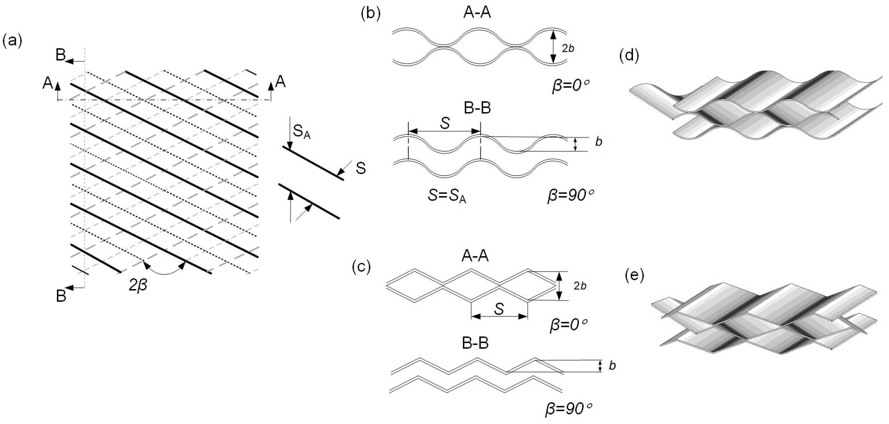
The gasketed PHE (GPHE) allows for disassembling for mechanical cleaning and repair. The GPHE consists of heat transfer plates schematically shown in Figure 1, which in a specific sequence, are assembled together in a heat exchanger and form the channels sealed by elastic gaskets. On assembly, the gaskets form the inlet and outlet manifolds for each of the two streams from which heat-exchanging fluids are distributed, to a system of channels where the heat transfer process takes place through the plate walls. The majority of commercially produced plates have corrugations inclined to the main flow direction that, on assembly, form criss-cross flow channels of complex geometry with multiple contact points between adjacent plates, as shown in Figure 2. It creates a strong, robust construction capable of withstanding high-pressure differences between streams, and stipulates high levels of turbulence leading to enhanced heat transfer. The plates are compressed in a pack on a frame between fixed and movable frame plates.
The gaskets are important elements of GPHE. They offer the possibility for it to be disassembled for maintenance and repair, and flexibility in adding or taking off plates and changing their arrangement. On the other hand, they are limiting the range of GPHE applications on temperature (from −60 °C up to 200 °C) and on pressure (from vacuum to 25 bar). For some aggressive media and extreme temperatures, the cost of gaskets can constitute a major part of the GPHE cost. It leads to the development of new PHE constructions not requiring gaskets, but also limiting access to the heat transfer surface.
Brazed PHE (BPHE) consists of a number of corrugated plates stamped from stainless steel and brazed by filler material on a periphery and around ports to seal the channels and arrange stream distribution between channels instead of gaskets. The adjacent plates are brazed between themselves in multiple contact points of corrugation. It makes a strong channel structure, capable of withstanding high inside pressure and not requiring special frame plates to keep the plates together. The standard BPHE with copper as a brazing material is capable of working at temperatures from −195 °C to 226 °C and pressures up to 31 bar. That range can be increased even more with specialised designs. The channels of BPHE are of the same geometry as shown in Figure 2, but with the small addition of filler metal at contact points and more favourable conditions of flow in port zones (see Figure 1), as the cross-section has no decrease in areas with rubber gaskets. It renders some differences in the flow hydrodynamics compare to GPHE; more details can be found in books, e.g., [2].
Welded PHE (WPHE) has a pack of corrugated plates welded on the periphery to seal the channels and to arrange stream distribution between channels. There are two major types of WPHE [3]. One is a plate-and-block WPHE in which plates are squared and welded on the periphery, creating one pass block system of channels for the cross-flow of heat exchanging streams. Different combinations of such blocks create the system of passes for streams, which is organised by special baffles. The welded core of such PHE is encased in a dismountable shell. The most used plate-and-block PHE type is the CompablocTM, originally developed by Vicarb and now produced by Alfa Laval. It is capable of operating at a pressure of up to 42 bar and temperatures from −45 °C to 371 °C. The geometry of channels is the same as shown in Figure 2, but the entrance and exit of flow are at the full channel width, which makes the share of pressure losses at these zones much smaller than in GPHE. However, the cross flow at the channels give a considerable difference in thermal design (for more details, see e.g., [2]) Another type of WPHE is a plate-and-shell heat exchanger. It consists of a pack of round plates encapsulated in a cylindrical shell, and can provide a counter-current flow of streams in a one-pass or multi-pass mixed channels arrangement. In some modifications, it can operate at a pressure of up to about 150 bar and a temperature of up to 750 °C. The main difference from other PHE types is the feature of flow distribution from ports at opposite sides of the round plates on full plates width.
The successful operation of PHEs for single-phase heat exchange stipulates their application for condensation of different vapours in a number of processes. A number of research works have been conducted in recent years concerning construction development and heat transfer enhancement in condensation at PHEs. In this paper, the results of studies on heat transfer and pressure drop in the two-phase condensing flow inside channels of PHE with different geometries of corrugations are discussed, with the aim of summarising the acquired knowledge and determining future directions and perspectives.

2. Heat Transfer in Two-Phase Condensing Flows Inside PHE Channels

The structure of two-phase flow in the PHE channels of complex geometry is very different from that in tubes and flat wall channels. It does not allow for the calculation of heat transfer coefficients in condensation processes inside the PHE channels and the correlations published for tubes. The possibilities of theoretical process investigation in such channels of complicated geometry are very limited, and the main method of obtaining reliable correlations is an experimental study. There are a number of review papers analyzing the results of earlier publications on condensation inside PHE channels.

2.1. Overall Analysis of Published Studies

Farahani et al. [4] discussed publications on experimental investigations of refrigerants condensation in PHE channels. The main difference with condensation in tubular heat exchangers is a much more complex flow structure in the PHE channels than in tubes. This complicates the process and makes it difficult to obtain correlations for thermal and hydraulic design. In the majority of industrial applications of condensing pure vapours, the film condensation takes place and the thermal resistance on the vapour side is created by the heat transfer in the film of condensed liquid. It was observed that most of the analyzed studies are made for average heat transfer coefficients, and local data are very limited. The accuracy of correlations presented in some of these papers is estimated by comparison with a databank of 532 data points. These are selected from six experimental kinds of research on the condensation of three refrigerants in channels of different PHEs. All correlations are most accurate for the data on which they were received. Even the best accuracy correlations predict all data banks with an error of up to 50% and even more. A similar analysis is presented by Eldeeb et al. [5], including some additional research data. The conclusion was also made that correlations are capable of predicting accurately enough only those data on which they were obtained. On others, the accuracy is not better than that shown in [4]. Tao and Ferreira [6] reviewed data from 16 studies on condensation in PHEs of 18 different refrigerants, with the exclusion of ammonia. The databank of 2376 data sets was considered, and on its base was estimated the accuracy of correlations presented by different authors. The best correlation predicted 93% of data with accuracy within ±50%, and all others had an accuracy of much lower. The heat transfer correlations for condensation in PHEs used for the organic Rankine cycle (ORC) and their influence on system performance were analysed in the paper by Zhang et al. [7]. The optimisation of the PHE condenser using correlations presented by five different authors gave a resulting heat transfer area dissimilar by up to 70%, with an optimal chevron angle of 35°. The examined correlations were received based on experiments with five small-sized PHEs, including two gasketed GPHEs (length of about 500 mm) and three brazed BPHEs (length of about 300 mm) with corrugations inclined on 45°, 55°, 60°, and 65° and 70° to the main flow direction. The optimised heat transfer area is from 75.8 to 132.0 m2, which is questionable to obtain from such small plates. The comparison of correlation accuracy was performed on 237 data close to ORC cycle application conditions. It gave a somewhat better accuracy with the mean absolute percentage deviation of 15.8%, while some data deviations acceded 30%. One of the considered correlations was that presented in the paper by Zhang et al. [8], as having much better accuracy than others, but on the data set of the paper [7] it showed lower accuracy. Another review of different correlations was proposed in papers for heat transfer during condensation of refrigerants for ORC systems and heat pumps was presented by Zhang et al. [9]. A new correlation for these conditions was proposed that the error was within ±30% for 98% of data. It was observed that the development of correlations for heat transfer in PHEs applicable for a range of geometrical parameters still requires further study. Eleven different correlations presented in publications were analysed by Shah [10], based on comparison with data from 25 sources in the range of the plate corrugation angles from 30° to 75°, 17 different refrigerants and data from one paper on steam condensation. The best-examined correlations have accuracy ±50% for 93% of the data. The modified correlation is proposed that predicts 83% of data with accuracy ±30%. The author’s conclusion is that there is a need for improvement in heat transfer correlation accuracy. The comprehensive review of heat transfer intensification in PHE by Kumar et al. [11] contains one chapter on heat transfer in two-phase flows, with just a few papers mentioning condensation in PHE channels.
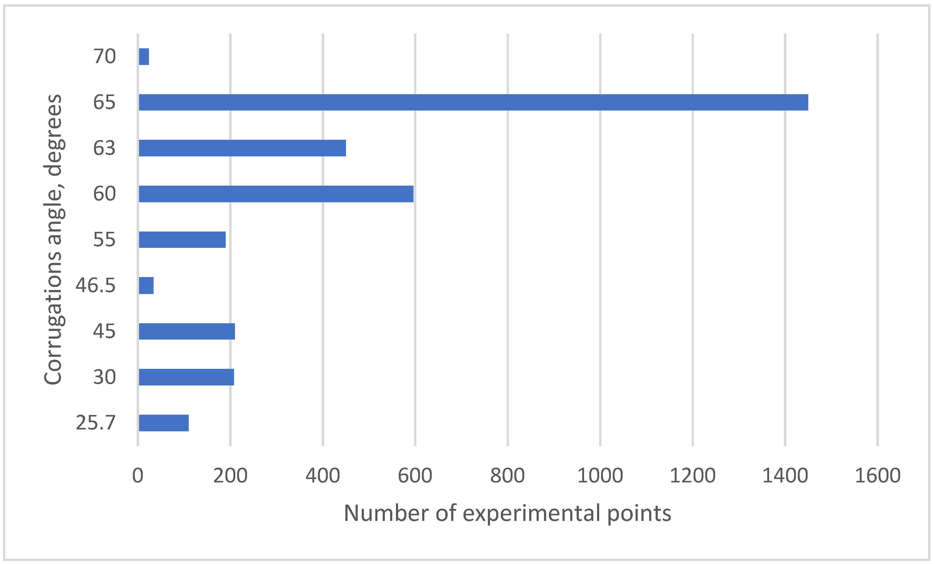
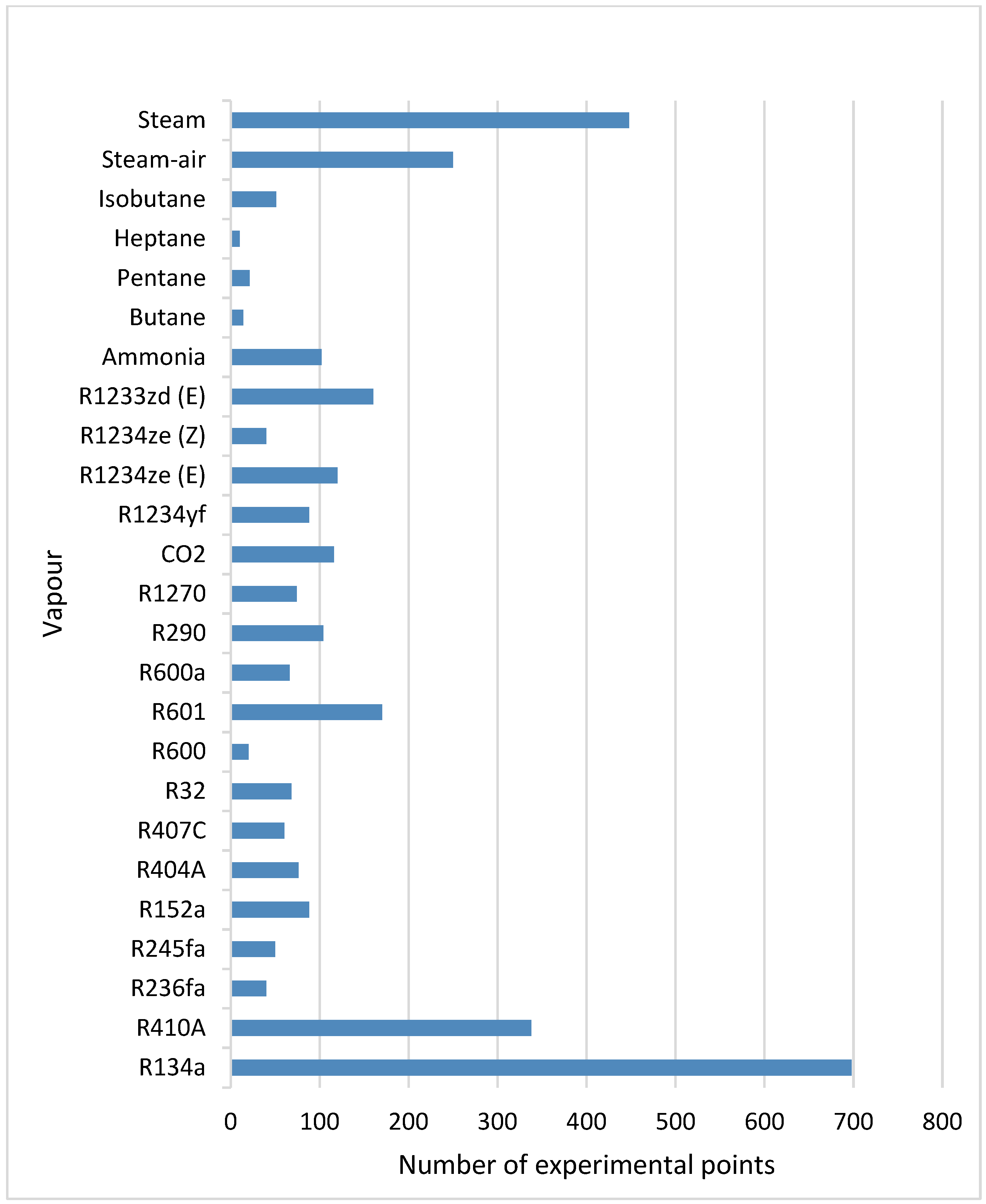
The analysis of the data reported in the literature reveals the wide variety of investigated condensing vapours by nature and PHEs by their construction and corrugations geometries. It is illustrated by the distribution of the numbers of experimental points received for different plate corrugation angles, presented in Figure 3, and different condensing vapours in Figure 4. The diagrams are obtained by summarising the data of previous works reported in papers [6,9,10] and paper by Würfel and Ostrowski [12] with a small addition of publications in 2022. The total number of 3272 data points on heat transfer in PHE channels in condensation from 32 papers are included. The big difference in experimental point numbers obtained for different vapours and corrugation angles is one of the explanations for the difficulties of all data generalisation by the single correlation based on averaged process parameters, with little accounting for the PHE construction features.

2.2. Recent Developments in PHE Condensers for Waste Heat Recovery, Heat Pumps and ORC Cycle

The recent studies of condensation in PHEs are mostly related to experiments and simulations of BPHEs as components of heat recovery systems using different refrigerants. The optimisation of a BPHE condenser for the system of recovering waste heat from the cooling of electronic equipment was presented in a paper by Amalfi et al. [13] for BPHE as an element of thermosyphon. By optimising corrugations of the BPHE plate with 220 mm length and 110 mm width for refrigerant R1234yf, the optimal corrugation angle was obtained as 48° with its height 3 mm and pitch 4 mm. The details of the modelling were not revealed, which does not allow us to judge the accuracy of the obtained results.
The possibility to improve heat pump and ORC systems efficiency by changing pure refrigerants on zeotropic mixtures, has stipulated research on heat transfer at such mixture condensation inside PHE. The condensation of R134a/R245fa zeotropic mixture in small BPHE was studied in paper [14]. By modifying the correlation available in the literature, the authors approximated their experimental data with a mean absolute error of 12.2%. Condensation of three pure fluids, Novec649, HFE7000 and HFE7100 and three of their zeotropic mixtures in small BPHE, was studied experimentally by Blondel et al. [15]. The available literature correlations were examined, and a correction factor was introduced for one of those correlations, which allowed us to obtain a condensation heat transfer prediction with deviations up to ±50%. It was noted that the used mixtures do not allow to obtain better ORC plant performance than pure fluids. The results of the experimental study of zeotropic mixture R1234ze(E)/R1233zd(E) condensation in small BPHE are reported by Huang et al. [16]. The modified correlation of the form used in the paper [14] gave good results on heat transfer prediction, with a mean absolute error ±4.2%. By the authors’ conclusion, the condensation in their experiments was controlled by shear. More zeotropic mixtures were analysed by the same authors in [17] at temperatures from 70 to 90 °C. A modified correlation of paper [16] for the same studied BPHE was adopted with a mean absolute deviation ±7.1%. It shows that in specific process conditions at the same BPHE, accurate enough correlations can be obtained. These correlations can be used for the design of such BPHE in conditions close to experimental. However, they cannot be readily applied in other process conditions for PHE of different sizes and geometry.

2.3. Studies of Refrigerants with Low Global Warming Potential

Jung et al. [18] experimentally investigated the condensation of low-GWP (global warming potential) refrigerants R1234ze(E) and R1233zd(E) in small-sized BPHEs which was different than in paper [17] with the corrugations angle 30° and 60°. The resulting correlation for heat transfer had deviations from the experiment ±20% for 95% of the authors’ experimental data. However, the comparison with experiments of other scholars gave deviations up to 50% and more. The experiments described by Ko et al. [19] with the same BPHEs and additional refrigerant R124 gave similar results of correlation accuracy for the authors’ data, and big deviations from other data published in the literature. For experiments with condensation of R1233zd(E) inside channels of the same BPHEs in paper by Kwon et al. [20], a correlation was received for Nusselt numbers with deviation from the authors’ experiments data ±25% for 92.9% of data. There was an error of more than 50% from other literature data. In that paper there were also reported results of experiments on R1233zd(E) condensation in plate-and-shell PHE. However, due to maldistribution in this PSHE, it was not recommended as the condenser and data were not correlated. The condensation of refrigerants R1234ze(E) and R134a in other BPHE, with about two times longer plates, was studied by Cattelan et al. [21]. The experimental results on heat transfer were compared with predictions by different correlations from the literature. The best accuracy of ±30% for 99% of data was received with correlation from the paper [9].
The influence on the condensation of refrigerants R1234ze(E) and R134a of the corrugation inclination angle was studied experimentally at high pressures (up to 3.24 MPa) in the paper by Miyata et al. [22], based on chevron type small PHEs (channel length 200 mm). The chevron angle on plates of three tested PHEs was 30°, averaging 47.5° and 65°. The increase of heat transfer coefficients at higher chevron angles was observed, but only qualitative analysis was given, and no correlations were presented. The further increase of the corrugation angle to 75° was studied in the paper [23] with the same refrigerant at a pressure of up to 4.91 MPa. No considerable effect on condensation heat transfer with an angle increase from 65° to 75° was observed.
The condensation of ammonia (NH3) in gasketed PHE was studied by Tao et al. [24]. The channels of GPHE had a small hydraulic diameter of 2.99 mm corrugations on plates inclined at 63°. The plate length between ports was 666 mm, which is much bigger than in small BPHEs. The data on heat transfer were compared with correlations previously published in the literature. The best predictions were achieved with deviations of ±30% for 98.1% of the data. The transparent model of the plate was made to analyse the flow structure in the PHE channel during the condensation of NH3, as described by Tao et al. [25]. Based on the experimental results, the map of flow patterns was built, indicating the structure of two-phase flow at the main corrugated field and at the channel entrance and exit. The flow patterns were predominantly film flow and partial film flow. The difference with other refrigerants condensation is discussed, and were mostly influenced by the bigger density’s ratio of phases. No correlations for heat transfer were proposed, formulating it as the task for the future.

2.4. Local Process Parameters

In all considered papers, the averaged full PHE surface area heat transfer coefficients are studied, and their correlations as a function of averaged process parameters in the channels are used. In vapour condensation inside the channels, all process parameters are changing considerably along the heat transfer surface, with the vapour part gradually transforming to liquid condensate. The flowrate of the gaseous phase decreases which leads to smaller vapour velocities, a decline of shear stresses between phases and a lessening of their interaction. More detailed information about local process parameters is required to account for these phenomena. Wang and Kabelac [26] experimentally investigated quasi-local parameters in the process of R1234ze(E) and R134a refrigerants condensation inside the channels of gasketed PHE, with the length of the plates’ main corrugated area 0.72 m. The corrugation angles on alternated plates forming channels were 27° and 63°, which creates a mixed channel with an average corrugation angle of 45°. The surface of the plates in one channel (of a total of four) had special micro pits on the vapour side. The local parameters were measured using thermocouples installed in 7 places along the channel, on the cooling water side and on the plate wall. The comparison of local heat transfer coefficients with correlations proposed by different scholars has shown considerable discrepancies, with the root mean square error (RMSE) of 41.2% in the best case. A new correlation for local heat transfer was proposed giving RMSE = 14.5%. In a further study with the same PHE [27], the correlation for heat transfer was modernised, giving RMSE = 10% in comparison with experimental data on local heat transfer. The author also obtained Nu correlation for heat transfer in a single-phase flow of cooling water, but with strange power 0.2 at Re number in the turbulent regime. It somewhat undermines the credibility of the results. Longo et al. [28] investigated the local heat transfer on the condensation of R32 and R410a refrigerants in a specially designed model of BPHE, with a plate length of 272 mm and corrugation angle of 65°. The plate thickness was 10 mm, and 36 thermocouples were installed on two adjacent plates in nine positions along the length of the plates to measure local wall temperatures and heat fluxes. The comparison of local heat transfer coefficients with a calculation by different correlations from the literature, has shown good agreement with the Nusselt equation for mass flow rates below 20 kg/(m2s). It is an interesting result, even when the local heat transfer coefficients were determined by an equation for averaged values. At higher flow rates up to 30 kg/(m2s), the agreement with Nusselt theory still remains for vapour quality below 0.5. At a higher vapour quality, the heat transfer coefficients are increased due to vapour action on the condensate film. Other correlations obtained on the process averaged parameters give a better agreement at high vapour qualities and flow rates, but overall cannot adequately describe the local heat transfer coefficients distribution. With such a mechanism of process development, the approach proposed by Thonon and Bontemps [29] of modelling with small channel zones by averaging the heat transfer coefficients obtained by the Nusselt correlation, and by an equation for high-velocity vapour, could be promising.

2.5. Condensation of Steam and Other Process Vapours

The analyzed review papers and recent studies on condensation are mainly concerned with refrigerants, as nowadays the most quickly developing area is due to increased interest in heat pumps and ORC systems. The papers on the condensation of steam and other process vapours were mainly published on earlier dates. There are considerable differences in approaches to problem solutions, as refrigerant vapour densities at working conditions are usually much higher than the density of steam in industrial applications of steam condensers. The results of an experimental study on local and average heat transfer during condensation of refrigerant R134a and steam inside channels of GPHE are reported by Müller and Kabelac [30]. The plate with a length of heat transfer area of 0.936 m and corrugations height of 3 mm was used. Two channel types with plate corrugation angles of 63° and 27° were examined. In modelling, the approach of division channels on small zones along its length was used. In the condensation of steam, a significant drop of pressure that leads up to a 25 °C drop in saturation temperature was observed, while for refrigerant it was not more than 1 °C. This has a significant effect on overall heat transfer and requires PHE calculation on local process parameters. The applicability of heterogeneous and homogeneous flow models and different correlations for calculations on local process parameters is discussed. The attempt to correlate average heat transfer coefficients in the condensation of vapour mixture of water-ethanol in PHE channels was made by Zhou et al. [31]. As a result, the correlation as a function of the Nu number from the Sherwood number (Sh), Re number and three other dimensionless numbers was received, predicting experimental data with deviations up to 32%. The strange modification of the Sh number and Re in power 5.6288 renders its low credibility. Another strange correlation with an average deviation smaller than 5% was additionally proposed. Bringing forward information known since 1993 [32], the trick of correlating the average Nusselt number by function from the heat load (to which Re of the condensed liquid is directly proportional) is divided on the same temperature difference at which the heat transfer coefficient is determined. It gives small deviations of data, but little real information that can be simply lost with such a way of data treatment. It is explained in more detail in a book by Wang et al. [33]. The calculations on local process parameters avoid such errors. This is shown in the modelling of water-ethanol mixture condensation by Tovazhnyansky et al. [34].

2.6. The Accuracy of Heat Transfer Correlations for PHE

The heat transfer correlations are the basis for PHE thermal design, and their accuracy directly influences the resulting size and cost of commercial PHEs selected for the required process conditions. The analysis of available generalised correlations for average process parameters on large sets of experimental data, presented in Section 2.1, has shown that the deviation of predicted heat transfer coefficients from experimental ones can reach 50% and more. It does not guarantee quality selection and accurate design of PHE as a condenser. In developing all correlations, the process is divided into gravity-controlled and convection-controlled areas, with a transition zone between them. When condensation is controlled by gravity, the Nusselt Equation (1) for vapour film condensation on a flat vertical wall is applied in all papers, with possible modifications for wavy film flow.
h g c = 0.943 [ g ρ L ( ρ L ρ G ) λ L 3 r μ L L p Δ T ] 0.25
where hgc is film heat transfer coefficient, W/(m2·°C) g is the acceleration of gravity, m/s2; ρL and ρG are densities of liquid and vapour, kg/m3; λL is the thermal conductivity of liquid, W/(m °C; r is the latent heat of condensation, J/kg; μL is the dynamic viscosity of the liquid, Pa·s; Lp is plate length; ΔT is the difference of vapour saturation temperature and wall temperature, °C.
Equation (1) can be rearranged to express the averaged film heat transfer coefficient from the liquid flow rate, and correspondingly from the liquid phase Reynolds number ReL. This is shown in a series of Equation (2), illustrating the link between the average heat transfer coefficient hgc, averaged specific heat flux q [W/m2], liquid mass flowrate through the unit of the cross-section area GL [kg/(m2 s)] and ReL. It accounts for the hydraulic diameter dh which is determined as the ratio of four cross-section areas f [m2] to the wetted perimeter Π [m].
h g c = q Δ T = G L f r Π L p Δ T = G L d h r 4 L p Δ T = Re L r μ L 4 Δ T
Expressing ∆T from Equation (2) and substituting into (1) after some algebraic manipulations gives:
h g c = 1.47 λ L Re L 1 3 g ρ L ( ρ L ρ G ) μ L 2 3
Equation (3) is another form of Nusselt Equation (2) for the average film heat transfer coefficient. It is more convenient in heat exchanger calculations, not requiring iterations on ∆T. It is discussed in paper [10], where the coefficient in (3) is taken at 1.32 for no explained reason. The introduction of the area enlargement ratio ϕ as a multiplier makes it closer to 1.47, but it still does not clarify the situation. There is also no correction for film waves or turbulence discussed in the paper [29].
At high vapour velocities, the increased shear stress at the gas–liquid interface can intensify heat transfer considerably in the condensate film, and heat transfer coefficients become higher than those calculated by the Nusselt equation. The condensation becomes controlled by shear forces on the condensate film surface. In these conditions, the majority of authors are correlating their experimental data on heat transfer using the equivalent Reynolds number Reeq determined by Equation (4):
Re e q = G [ ( 1 x ) + ( ρ L ρ G ) 0.5 ] d h μ L
where x is vapour quality; dh is the hydraulic diameter of the channel.
The boundary between gravitation-controlled and shear-controlled regimes are estimated at Reeq at about 1600. At higher values of Reeq the heat transfer coefficients are calculated by correlations developed at conditions of shear-controlled condensation. In some studies, the bigger the values for heat transfer coefficients calculated by equations for gravity-controlled and shear-controlled condensation are taken. The analysis of the different correlation’s accuracy in predicting experimental data, based on big data banks (about 2000 data points), was presented in papers [6,10]. In both papers, the best accuracy results were obtained for the shear-controlled area correlation proposed by Longo et al. [35] with Equation (5).
Nu s c = h s c d h λ L = 1.875 ϕ Re e q 0.445 Pr L 0.333
here, PrL is the liquid Prandtl number; ϕ is the plate’s surface area enlargement factor because of corrugations.
The accuracy of correlation (5) in the prediction of big general data banks collected by the authors of some papers (see Table 1) is rather low. The deviations from experimental data reach up to 50% and more. It is not acceptable for the design of commercial PHEs. The attempts by different authors to improve the accuracy of correlations in this form by adding other parameters and dimensionless numbers worsens the accuracy of prediction, as shown in the analysis in papers [6,10].
To improve the accuracy of heat transfer prediction in the paper [7], it was proposed to obtain more accurate correlations for specific conditions of heat pumps and ORC cycle applications. For such conditions, Equation (6) was proposed in the paper [8], in which predictions deviate from an experiment with a Mean Absolute Error (MAE) of 6.4% but in a narrow range of data (Table 1).
Nu s c = h s c d h λ L = 4.3375 Re e q 0.5383 Pr L 0.333 Bd 0.3872
where Bd = g(ρL − ρG)dh is Bond number; σ is surface tension, N/m.
For the conditions of heat pumps and ORC in the paper [8], this equation was modified by introducing the ratio of liquid and gas densities. It has shown the deviations with MAE 8.9% for a somewhat bigger set of experimental data, as shown in Table 1.
Nu s c = h s c d h λ L = 0.4703 Re e q 0.5221 Pr L 0.333 Bd 0.1674 ( ρ L ρ G ) 0.2126
The big errors in correlating large databanks of experimental data on heat transfer by different correlations for average process parameters are explained by two factors: (1) the change of process parameters and its thermophysical features not accurately accounted for on average; (2) the data are obtained at PHEs of different sizes and designs produced by various manufacturers. It explains why the rather good accuracy of the authors’ own data correlations becomes much worse with a comparison of other data. The same situation was with single-phase correlations for heat transfer in PHE, the process less complicated and more studied than condensation. The generalised correlations for single phase flow proposed by Martin [36] gave errors for the friction factor over ±65% and for heat transfer over ±33%. This was not much improved by later generalisation attempts in the paper by Dović et al. [37], as the data for comparison included heat transfer test results for commercial plates of different sizes, and experiments on the models of the corrugated field without ports and distribution zones (see Figure 1). The correlation of data for PHE channel models separately by Arsenyeva et al. [38] gave deviation of the experimental results on friction factors not more than ±20% and on Nu numbers in the limits of ±15% in a broad range of corrugation parameters, including the corrugation angle from 14° to 65°. These correlations can also be used for modelling heat transfer in single-phase flows in commercially produced PHEs by accounting for pressure losses in ports and distribution zones on commercial plates, as discussed in the paper [39]. These correlations were employed in the mathematical modelling of steam condensation from steam-air mixture in three models of the PHE main corrugated field, with the same corrugation angle to the main flow direction 60° and different corrugations heights 5.0, 7.5 and 10.0 mm [40]. The mathematical model is presented by the system of ordinary differential equations, which is solved by dividing the PHE channel into small-sized segments along its length. The equations for the calculation of heat and mass transfer coefficients are received using heat, mass, momentum analogies on data of correlations for friction factors. The solution is performed with a specially developed computer program. The model validity was confirmed by comparison of model predictions, with experimental data on the steam–air mixture temperature on the channels exit, with a root mean square error of 1.73 °C and the total heat load with a relative root mean square error of 2.03%. The condensation of steam in the presence of air as a non-condensing gas is significantly different from pure vapour condensation by the presence of diffusion resistance from flow core to condensate film, which becomes predominant with an increase of air concentration in the mixture. However, the method can also be used for pure vapours condensation, where the diffusion resistance from flow core to condensate film is absent.

2.7. The Thermal Modelling and Design of PHE Condensers

The modelling of pure vapour condensation in PHE channels by local process parameters was performed in a number of earlier studies. Arman and Rabas [41] were used in the incremental design procedure for small segments of the heat transfer surface. It allowed us to calculate the process of pure ammonia and propane/butane mixture condensation in plate-and-frame PHE, using a semiempirical equation for high-velocity vapour condensation obtained earlier for horizontal tubes. This equation validity for steam condensation in PHE channels was confirmed in an experimental study of local heat transfer coefficients by Tovaznyansky and Kapustenko [42], but with a correction factor of 0.93. Its good accuracy was also confirmed in the paper by Wang et al. [43], but also with some overestimation that was proposed to account for by decreasing power in the correlating equation. It was done in paper [44] for steam condensation at the PHE channel with a special cross-section. The method of segmental modelling by local process parameters was used by Gullapalli [45] for the condensation of steam and some refrigerants in brazed BPHEs. The methods of modelling PHE as a condenser considering the local process parameters, allow accounting for the changes in flow structure and process mechanism along the PHE channels. It enables the improvement accuracy of PHE modelling and design. At the same time, it requires reliable correlations to calculate local heat transfer coefficients. The methods for prediction of pressure losses in condensing two-phase flow in PHE channels are of increased importance, as the change of pressure along the channel can decrease saturation temperature, local temperature differences and overall process intensity.

3. Pressure Drop in Two-Phase Condensing Flows Inside PHE Channels

The pressure drop of two-phase flow condensing in PHE channels can considerably influence the design of PHE, as in many cases of industrial applications, it is strictly limited. Besides, it leads to the change of pressure inside the channel and to a diminishing temperature of vapour saturation, decreasing the driving force of the heat transfer process. The change of static pressure in condensing the two-phase flow inside the PHE channel is determined by Equation (8):
d P m x d x = d P T P d x d d x ( ρ m x W m x 2 2 ) d d x ( ρ m x g x 2 )
where Pmx is the pressure of condensing flow, Pa; dPTP/dx is pressure loss due to friction (including form drug) in two-phase flow, Pa/m; ρmx is the density of two-phase mixture, kg/m3; Wmx is the velocity of the two-phase mixture, m/s; x is coordinated along thechannel, m.
In the right side of Equation (8), the second term corresponds to pressure changes due to flow acceleration and the third term due to a change of elevation in the gravitational field. The main difference compare to smooth tubes and channels is in the calculation of dPTP/dx, which is complicated by the complex flow structure in the PHE channels of complicated geometry. In the majority of heat transfer studies on vapour condensation in PHE channels, considered here in Section 2, the pressure drop is also investigated.

3.1. Correlations with Averaged Process Parameters

A comprehensive review of research results in a pressure drop in condensation inside PHE channels is presented in the paper [6]. The accuracy of different correlations is analysed based on a comparison with the database, including 1590 pressure drop data. Different approaches for the prediction of a pressure drop in condensing the two-phase flow were divided into three groups: (1) homogeneous flow model with a calculation of friction factor for two-phase flow; (2) separated phases flow model proposed by Lockhart and Martinelli for tubes [46]; (3) kinetic energy model, that considers PHE as local hydraulic resistance with averaged flow density. The comparison of correlations received using these approaches with experimental data has shown the extreme deviations from experimental results obtained for studies different from conditions considered by the authors of these correlations. Even the correlation proposed in the paper [6], which appeared the most accurate, has deviations of more than 50% for 12.5% of the considered database with RMSE = 49.9%. Such accuracy is not suitable for the design of PHEs in different process conditions that are required for their inclusion in optimisation software for heat exchanger networks (HENs), e.g., those considered in the paper by Wang et al. [47]. To improve prediction accuracy in [9], only conditions specific for ORC and heat pump systems were considered, and a new correlation was proposed. It gave deviations in the limits of ±30% just for one considered PHE geometry. The pressure drop in condensation inside the vertical PHE of the water-ethanol mixture was studied by Hu and Ma [48], and a new friction factor correlation was developed with a mean absolute deviation from experimental data of 18.67%. Experimental studies of pressure drop during zeotropic mixture R1234ze(E)/R1233zd(E) condensation [16] and R134a/R245fa mixture were correlated with accuracy ±30%. For condensation of R-1234ze(E) and R-1233zd(E) refrigerants in small BPHE, the accuracy for the proposed friction factor correlation ±20% was reported in [18], but deviations from other data are much bigger. For a wider range of refrigerants, another paper [19] gives even worse results for the pressure drop prediction. For condensation of R-1233zd(E) in small BPHE, another friction factor correlation was received [20], with 89.1% of data predicted with error ±25%, but with much more deviations in the data of other studies. The application of the Lockhart-Martinelli approach for steam condensation in plate-and-frame GPHE by Wang et al. [49] gave an error in the prediction of pressure drop in the limits of ±12.5%. With this approach, the hydraulic resistance correlations in PHE channels are accounted for, which makes it preferable for the prediction of pressure drop in PHE channel geometries different from those investigated.

3.2. Pressure Drop Prediction with Local Process Parameters

In all considered studies, the average condensation process parameters were used in obtaining pressure drop correlations in PHE channels. As was discussed in Section 2, it does not permit accounting for the change of local process parameters, and does not permit accurately correlating the data obtained on PHEs of different construction and sizes produced by different manufacturers. The lack of theoretical background does not permit the widening of the obtained correlation to the condensation of other vapours with different thermo-physical properties. To avoid these drawbacks of averaging solutions, modelling of the condensation process in brazed BPHE in [45] was used for discretisation of the PHE channel on small zones along its length. For pressure drop calculation, the approach of Lockhart-Martinelli was used, which gave acceptable accuracy results.
The experiments on the condensation of the steam–air mixture inside the models of the PHE channels’ corrugated fields were described in paper [50]. There were five samples of PHE channels with corrugation angles of 30°, 45°, and 60° and spacing of 5.0, 7.5 and 10.0 mm. The attempts to correlate data using averaged parameters with the friction factor of the homogenous model gave deviations of more than 100%, and with Lockhart-Martinelli separated phases, model deviations up to 50% and more. The calculations using local process parameters on small increments of channel length gave much better results. Using the Lockhart-Martinelli model near the steam entrance until the Re of the liquid phase is smaller than 125, and for another channel, the dispersed-annular flow model of Boyko and Kruzhilin [51] gave predictions with deviations not exceeding ±30%. The use of a combined approach of the separated flow model and dispersed-annular flow model, with the inclusion of the Weber number accounting for the influence of surface tension, enabled the prediction data with relative RSME = 13.6% and deviations in the limits ±20% for prediction of 95% of data for all experimental samples. It shows the advantage of using calculations on local process parameters, and it is important to use a correct two-phase flow model corresponding to the real flow structure in the PHE channel.

4. The Structure of Two-Phase Condensing Flows Inside PHE Channels

The two-phase flow structure is one of the main factors determining the character of heat transfer and pressure losses during the condensation of vapours in PHE channels. Its change can considerably influence the relations when determining the process intensity that corresponds to certain flow models. The comprehensive analysis of different downward flow structures during vapour condensation in PHE channels was made in the paper by Tao et al. [52], based on previously published research results on visualisation studies of two-phase flows, e.g., the paper by Grabenstein et al. [53]. There are different overall flows depending on the corrugation angle: crossing flow along the furrows at a small corrugations angle and longitudinal wavy flow when the corrugation angle is large. The flow patterns of the two-phase flow depend on vapour quality, flow rates, and liquid and vapour properties. There are partial film flow, film flow, annular, slug-annular, churn, slug, slug-bubbly, regular-bubbly and dispersed-bubbly flow patterns. The combined flow patterns maps are built and compared to those for the downward two-phase flow in tubes, which cannot be directly used for PHE. The condensation mechanisms controlled by gravity and by convection are discussed, and the factors influencing them are determined. The majority of studies considered in [52] are performed with water and air as two phases. Only in paper [53] was the condensation of R365mfc refrigerant studied, as in an earlier work [54] for PHE with plates corrugation angle 27° and 63°. The results of the flow visualisation study for the condensation of ammonia in PHE channels with corrugations angle 63° are reported in [25]. The main flow patterns observed were partial and full film flow, the transition between which was mainly determined by wetting properties. Only qualitative characterisation was made with graphs, with no quantitative correlations. The qualitative picture was also received in the visualisation study of water–air two-phase flow reported by Buscher [55] for the PHE channel with plates corrugation angle 75°. The partial and full film flow, homogenous and bubble flow patterns were observed. The visualisation study of R-1234ze(E) condensation in a channel of plate-and-frame GPHE with commercially produced plates was reported by Lee et al. [56]. Flow pattern with condensate film was observed on the entire plate surface, with film thickness unevenly distributed across the channel width. Steady film flow and pulsating film flow zones were reported. For the transition between these flow patterns, the correlation involving Weber number was proposed.
With the rapid development of computer technologies, the computational fluid dynamic (CFD) became a powerful tool for detailed analysis of hydrodynamics in different flows, now including two-phase flows in the PHE channels of complicated three-dimensional geometry. The CFD modelling of two-phase water–air upward flow in the PHE channel was reported by Zhu and Haglind [57]. The results of different flow patterns were confirmed by comparison with experimental data on flow visualisation available in the literature. The results are mostly concerned with boiling, but are also interesting as an example of two-phase flow modelling. The condensation of the ethanol–water mixture in a channel formed by commercial PHE plates was simulated with CFD by Zhang et al. [58]. The overall pictures of process temperature and pressure distributions on the plate area are presented, as well as graphics of parametric dependences for heat transfer coefficients and pressure drop from mass flow rate and dryness. The resulting correlations for the Nu number and friction factor are obtained, and accuracy compared to experimental data published in the literature looks inexplicably good compared to other experimental correlations, which raises doubts about the credibility of this paper part. Overall, the available data on CFD modelling of the condensation process shows that it still requires further development.
The information on the flow structure of the condensing two-phase flow and its change along the channels is important in developing reliable mathematical models for process simulation in PHE and their design in industrial applications. Besides, it is valuable for the development of new constructions specific to this process. For example, increased volume flow rates of vapour at the condenser inlet can require enlarging cross-section areas of inlet collector and ports, leading to the development of specialised PHE, e.g., AlfaCond [59] or BPHE with different channel gaps. The significant change in flow velocities can be adopted by varying cross-section areas of channels [44] and its proper correlation with a channel for cooling media.

5. The Conclusions and Future Prospects

PHE in processes of vapour condensation is the fast-developing type of heat transfer equipment. Their main advantages compared to traditional shell-and-tube heat exchangers are compactness, small mass and inner volume, and enhanced heat transfer. The construction of PHE can be adapted to the required conditions of specific applications as condensers.
Flow structure in PHE and heat transfer during condensation is considerably different from flows in smooth tubes and flat-wall channels. It stipulates the studies on heat transfer enhancement and pressure losses in condensing two-phase flows inside PHE channels of complicated geometry. Presently, the plates with inclined corrugations are mostly used in PHEs for vapour condensation. Considerable numbers of experiments on condensation of different vapours in the PHE channels are found in the literature. The present analysis considered a total number of 3272 data points on heat transfer from 32 papers, with distribution on the number of studies by investigating the corrugation angle in PHE (Figure 3) and the nature of condensing vapour (Figure 4). There is a big difference in the experimental point numbers obtained for different corrugation angles and different vapours. The biggest numbers of studies are for the corrugation angles equal to 65 degrees and for different kinds of refrigerants. Such uneven distribution is one of the explanations for the difficulties of all data generalisation by the single correlation, based on averaged process parameters.
The corrugation inclination angle to the main flow direction is the main factor affecting PHE performance at the same corrugation height and form. The investigated range of corrugation angles that can have been studied in PHE is from 27° to 75°. The increase of corrugation angles in this range by data in the majority of research is leading to an increase of heat transfer intensity during vapour condensation, but also involves the rise in friction factor.
There are considerable differences in approaches to modelling, design and construction optimisation between PHE condensers for steam and some other process vapours and for refrigerants, in which vapours densities at working conditions are usually much higher than the density of steam and process vapours in industrial applications. In recent years the main subjects of studies on condensation in PHE channels are different refrigerants, as shown in Figure 4. It is explained by a fast development in heat pumps and ORC technologies, and the need for adequate correlations for prediction of PHE performance in such applications.
Correlations for the calculation of heat transfer coefficients and friction factors in a majority of studies are obtained for averaged process parameters. These correlations have acceptable accuracy in the limits of about ±20% only for investigated vapours and PHE tested in specific research. The attempts to correlate the data of other authors are giving much bigger deviations, about 50% and more. Better prediction of heat transfer and the pressure drop in condensation is achieved by using local parameters and based on the modelling and design of PHE for condensing duties. The detailed analysis of two-phase flows in PHE channels by using the visualisation approach and CFD modelling allows us to improve the understanding of this phenomenon.
The future progress in the field of vapour condensation using PHE would require advances in the following areas:
  • Further development of theoretical analysis and fundamental knowledge on heat transfer and hydrodynamics in condensing two-phase flows inside criss-cross flow channels, formed by plates with inclined corrugations of different geometries.
  • The experimental studies of heat transfer and pressure losses during different vapour condensation in PHE channels, with an emphasis on local process parameters at small zones of channels and their distribution on channels field accounting for plates corrugation geometry.
  • Experimental and theoretical studies of two-phase flow maldistribution inside PHE channels and between different channels in a system of channels at PHE with different numbers of plates.
  • A deeper understanding of condensing two-phase flow structures, the change between different flow regimes and their effect on heat transfer intensity and pressure losses based on the methods of flow visualisation and CFD modelling.
  • Reliable methods of PHE modelling and design for condensing duties, based on one-dimensional mathematical models accounting for the distribution of local process parameters along the channel length and the effects of flow distribution zones and port areas at commercially produced plates.
  • Developing the methods for optimisation of PHE and their plate constructions for specified conditions of the vapour condensation process.
  • Further development of methods and software for PHE condensers design and selection as part of heat exchanger networks in complex heat recuperation systems.
  • Improving constructions of PHE for condensation of different vapours, based on newly acquired knowledge of process phenomena with the increased potential of energy saving and a reduced footprint on the environment.

Author Contributions

Conceptualization, J.J.K. and L.T.; methodology, O.A.; formal analysis, P.K.; resources, J.J.K.; data curation, O.A.; writing—original draft preparation, P.K.; writing—review and editing, J.J.K.; supervision, L.T.; project administration, J.J.K.; funding acquisition, J.J.K. All authors have read and agreed to the published version of the manuscript.

Funding

This research was funded by European Commission and is a part of the HORIZON 2020 project RESHeat H2020-LC-SC3-EE-2020-1 on the basis of Grant Agreement No. 956255 and the OP VVV project “International mobility of researchers of the University of Technology in Brno II”, reg. No. CZ.02.2.69/0.0/0.0/18_053/0016962 (MeMoV II).

Data Availability Statement

Not applicable.

Conflicts of Interest

The authors declare no conflict of interest. The funders had no role in the design of the study; in the collection, analyses, or interpretation of data; in the writing of the manuscript; or in the decision to publish the results.

References

  1. Chong, C.T.; Fan, Y.V.; Lee, C.T.; Klemeš, J.J. Post COVID-19 energy sustainability and carbon emissions neutrality. Energy 2022, 241, 122801. [Google Scholar] [CrossRef] [PubMed]
  2. Klemeš, J.J.; Arsenyeva, O.; Kapustenko, P.; Tovazhnyanskyy, L. Compact Heat Exchangers for Energy Transfer Intensification: Low Grade Heat and Fouling Mitigation; CRC Press: Boca Raton, FL, USA, 2015. [Google Scholar]
  3. Arsenyeva, O.P.; Tovazhnyanskyy, L.L.; Kapustenko, P.O.; Khavin, G.L.; Yuzbashyan, A.P.; Arsenyev, P.Y. Two types of welded plate heat exchangers for efficient heat recovery in industry. Appl. Therm. Eng. 2016, 105, 763–773. [Google Scholar] [CrossRef]
  4. Vakili-Farahani, F.; Amalfi, R.L.; Thome, J.R. Two-phase heat transfer and pressure drop within plate heat exchangers. Encyclopedia of Two-Phase Heat Transfer and Flow II: Special Topics and Applications. 2016, pp. 145–215. Available online: https://www.worldscientific.com/ (accessed on 15 November 2022).
  5. Eldeeb, R.; Aute, V.; Radermacher, R. A survey of correlations for heat transfer and pressure drop for evaporation and condensation in plate heat exchangers. Int. J. Refrig. 2016, 65, 12–26. [Google Scholar] [CrossRef]
  6. Tao, X.; Ferreira, C.A.I. Heat transfer and frictional pressure drop during condensation in plate heat exchangers: Assessment of correlations and a new method. Int. J. Heat Mass Transf. 2019, 135, 996–1012. [Google Scholar] [CrossRef]
  7. Zhang, J.; Baldasso, E.; Mancini, R.; Elmegaard, B.; Haglind, F. Evaluation of Heat Transfer Correlations for Flow Condensation in Plate Heat Exchangers and Their Impact on The Design of Organic Rankine Cycle Systems. In Proceedings of the 5th International Seminar on ORC Power Systems, Athens, Greece, 9–11 September 2019; National Technical University of Athens: Athens, Greece, 2019; p. 147. [Google Scholar]
  8. Zhang, J.; Kærn, M.R.; Ommen, T.; Elmegaard, B.; Haglind, F. Condensation heat transfer and pressure drop characteristics of R134a, R1234ze (E), R245fa and R1233zd (E) in a plate heat exchanger. Int. J. Heat Mass Transf. 2019, 128, 136–149. [Google Scholar] [CrossRef]
  9. Zhang, J.; Elmegaard, B.; Haglind, F. Condensation heat transfer and pressure drop correlations in plate heat exchangers for heat pump and organic Rankine cycle systems. Appl. Therm. Eng. 2021, 183, 116231. [Google Scholar] [CrossRef]
  10. Shah, M.M. Heat transfer during condensation in corrugated plate heat exchangers. Int. J. Refrig. 2021, 127, 180–193. [Google Scholar] [CrossRef]
  11. Kumar, S.; Singh, S.K.; Sharma, D. A Comprehensive Review on Thermal Performance Enhancement of Plate Heat Exchanger. Int. J. Thermophys. 2022, 43, 1–68. [Google Scholar] [CrossRef]
  12. Würfel, R.; Ostrowski, N. Experimental investigations of heat transfer and pressure drop during the condensation process within plate heat exchangers of the herringbone-type. Int. J. Therm. Sci. 2004, 43, 59–68. [Google Scholar] [CrossRef]
  13. Amalfi, R.L.; Cataldo, F.; Thome, J.R. An optimization optimisation algorithm to design compact plate heat exchangers for waste heat recovery applications in high power datacenter racks. In Proceedings of the 18th IEEE Intersociety Conference on Thermal and Thermomechanical Phenomena in Electronic Systems (ITherm), Las Vegas, NV, USA, 29–31 May 2019; pp. 159–166. [Google Scholar]
  14. Zhang, J.; Elmegaard, B.; Haglind, F. Condensation heat transfer and pressure drop characteristics of zeotropic mixtures of R134a/R245fa in plate heat exchangers. Int. J. Heat Mass Transf. 2021, 164, 120577. [Google Scholar] [CrossRef]
  15. Blondel, Q.; Tauveron, N.; Lhermet, G.; Caney, N. Zeotropic Mixtures Study in Plate Heat Exchangers and ORC Systems. Appl. Therm. Eng. 2022, 219, 119418. [Google Scholar] [CrossRef]
  16. Huang, X.; Zhang, J.; Haglind, F. Experimental analysis of hydrofluoroolefin zeotropic mixture R1234ze(E)/R1233zd(E) condensation in a plate heat exchanger. Int. Commun. Heat Mass Transf. 2022, 135, 106073. [Google Scholar] [CrossRef]
  17. Huang, X.; Zhang, J.; Haglind, F. Experimental analysis of condensation of zeotropic mixtures from 70 °C to 90 °C in a plate heat exchanger. Int. J. Refrig. 2022, 137, 166–177. [Google Scholar] [CrossRef]
  18. Jung, J.H.; Ko, Y.M.; Kang, Y.T. Condensation heat transfer characteristics and energy conversion performance analysis for low GWP refrigerants in plate heat exchangers. Int. J. Heat Mass Transf. 2021, 166, 120727. [Google Scholar] [CrossRef]
  19. Ko, Y.M.; Jung, J.H.; Sohn, S.; Song, C.H.; Kang, Y.T. Condensation heat transfer performance and integrated correlations of low GWP refrigerants in plate heat exchangers. Int. J. Heat Mass Transf. 2021, 177, 121519. [Google Scholar] [CrossRef]
  20. Kwon, O.J.; Jung, J.H.; Kang, Y.T. Development of experimental Nusselt number and friction factor correlations for condensation of R-1233zd (E) in plate heat exchangers. Int. J. Heat Mass Transf. 2020, 15, 120008. [Google Scholar] [CrossRef]
  21. Cattelan, G.; Diani, A.; Azzolin, M. Condensation heat transfer of R1234ze (E) and R134a inside a brazed plate heat exchanger: Experimental data and model assessment. Int. J. Refrig. 2022, 143, 57–67. [Google Scholar] [CrossRef]
  22. Miyata, K.; Yanagihara, S.; Watanabe, N.; Mori, H.; Hamamoto, Y.; Umezawa, S.; Sugita, K. Effect of chevron angle on condensation heat transfer of refrigerants at high pressures in plate heat exchangers. Trans. Jpn. Soc. Refrig. Air Cond. Eng. 2018, 35, 383–388. [Google Scholar]
  23. Miyata, K.; Yamasaki, Y.; Kurose, K.; Hamamoto, Y.; Mori, H.; Umezawa, S. Cooling and condensation heat transfer and pressure drop of a refrigerant at high pressures in a chevron-type plate heat exchanger with high chevron angle. Mech. Eng. J. 2020, 7, 20-00107. [Google Scholar] [CrossRef]
  24. Tao, X.; Kirkenier, J.; Ferreira, C.I. Condensation of NH3 within a plate heat exchanger of small diameter channel. In Proceedings of the International Conference on Micro/Nanoscale Heat Transfer, Dalian, China, 8–10 July 2019; Volume 58905, p. V001T04A002. [Google Scholar]
  25. Tao, X.; Dahlgren, E.; Leichsenring, M.; Ferreira, C.A.I. NH3 condensation in a plate heat exchanger: Experimental investigation on flow patterns, heat transfer and frictional pressure drop. Int. J. Heat Mass Transf. 2020, 151, 119374. [Google Scholar] [CrossRef]
  26. Wang, R.; Kabelac, S. Condensation quasi-local heat transfer and frictional pressure drop of R1234ze (E) and R134a in a micro-structured plate heat exchanger. Appl. Therm. Eng. 2021, 197, 117404. [Google Scholar] [CrossRef]
  27. Wang, R.; Sun, T.; Polzin, A.E.; Kabelac, S. Experimental investigation of the two-phase local heat transfer coefficients for condensation of R134a in a micro-structured plate heat exchanger. Heat Mass Transf. 2022, 58, 1–18. [Google Scholar] [CrossRef]
  28. Longo, G.A.; Mancin, S.; Righetti, G.; Zilio, C. Local heat transfer coefficients of R32 and R410a condensation inside a brazed plate heat exchanger (BPHE). Int. J. Heat Mass Transf. 2022, 194, 123041. [Google Scholar] [CrossRef]
  29. Thonon, B.; Bontemps, A. Condensation of pure and mixture of hydrocarbons in a compact heat exchanger: Experiments and modelling. Heat Transf. Eng. 2002, 23, 3–17. [Google Scholar] [CrossRef] [Green Version]
  30. Müller, A.; Kabelac, S. The experimental determination of heat transfer and pressure drop during condensation in a plate heat exchanger with corrugated plates. Heat Transf. XIII Simul. Exp. Heat Mass Transf. 2014, 83, 337–349. [Google Scholar]
  31. Zhou, W.; Hu, S.; Ma, X.; Zhou, F. Condensation heat transfer correlation for water-ethanol vapor mixture flowing through a plate heat exchanger. Heat Mass Transf. 2018, 54, 3025–3033. [Google Scholar] [CrossRef]
  32. Wang, Z.Z.; Zhao, Z.N. Analysis of performance of steam condensation heat transfer and pressure drop in plate condensers. Heat Transf. Eng. 1993, 14, 32–41. [Google Scholar] [CrossRef]
  33. Wang, L.; Sunden, B.; Manglik, R.M. Plate Heat Exchangers. Design, Applications and Performance; WIT Press: Southhampton, UK, 2007. [Google Scholar]
  34. Tovazhnyansky, L.L.; Kapustenko, P.O.; Nagorna, O.G.; Perevertaylenko, O.Y. The simulation of multicomponent mixtures condensation in plate condensers. Heat Transf. Eng. 2004, 25, 16–22. [Google Scholar] [CrossRef]
  35. Longo, G.A.; Righetti, G.; Zilio, C. A new computational procedure for refrigerant condensation inside herringbone-type Brazed Plate Heat Exchangers. Int. J. Heat Mass Transf. 2015, 82, 530–536. [Google Scholar] [CrossRef]
  36. Martin, H. A theoretical approach to predict the performance of chevron-type plate heat exchangers. Chem. Eng. Process. Process Intensif. 1996, 35, 301–310. [Google Scholar] [CrossRef]
  37. Dović, D.; Palm, B.; Švaić, S. Generalized correlations for predicting heat transfer and pressure drop in plate heat exchanger channels of arbitrary geometry. Int. J. Heat Mass Transf. 2009, 52, 4553–4563. [Google Scholar] [CrossRef]
  38. Arsenyeva, O.P.; Tovazhnyanskyy, L.L.; Kapustenko, P.O.; Demirskiy, O.V. Heat transfer and friction factor in criss-cross flow channels of plate-and-frame heat exchangers. Theor. Found. Chem. Eng. 2012, 46, 634–641. [Google Scholar] [CrossRef]
  39. Arsenyeva, O.; Kapustenko, P.; Tovazhnyanskyy, L.; Khavin, G. The influence of plate corrugations geometry on plate heat exchanger performance in specified process conditions. Energy 2013, 57, 201–207. [Google Scholar] [CrossRef] [Green Version]
  40. Kapustenko, P.O.; Klemeš, J.J.; Arsenyeva, O.P.; Kusakov, S.K.; Tovazhnyanskyy, L.L. The influence of plate corrugations geometry scale factor on performance of plate heat exchanger as condenser of vapour from its mixture with noncondensing gas. Energy 2020, 201, 117661. [Google Scholar] [CrossRef]
  41. Arman, B.; Rabas, T. Condensation Analysis for Plate and Frame Heat Exchangers; HTD-Vol 314; Argonne National Lab.(ANL): Argonne, IL, USA, 1995; Volume 12, pp. 97–104. [Google Scholar]
  42. Tovazhnyanski, L.L.; Kapustenko, P.A. Intensification of heat and mass transfer in channels of plate condensers. Chem. Eng. Commun. 1984, 31, 351–366. [Google Scholar] [CrossRef]
  43. Wang, L.; Christensen, R.; Sunden, B. An experimental investigation of steam condensation in plate heat exchangers. Int. J. Heat Exch. 2000, 1, 125–150. [Google Scholar]
  44. Arsenyeva, O.; Tovazhnyansky, L.; Kapustenko, P.; Perevertaylenko, O.; Khavin, G. Investigation of the new corrugation pattern for low pressure plate condensers. Appl. Therm. Eng. 2011, 31, 2146–2152. [Google Scholar] [CrossRef]
  45. Gullapalli, V.S. Estimation of Thermal and Hydraulic Characteristics of Compact Brazed Plate Heat Exchangers. Ph.D. Thesis, Lund University, Lund, Sweden, 2013. [Google Scholar]
  46. Lockhart, R.W.; Martinelli, R.C. Proposed correlation of data for isothermal two-phase, two-component flow in pipes. Chem. Eng. Prog. 1949, 45, 39–48. [Google Scholar]
  47. Wang, B.; Arsenyeva, O.; Zeng, M.; Klemeš, J.J.; Varbanov, P.S. An advanced Grid Diagram for heat exchanger network retrofit with detailed plate heat exchanger design. Energy 2022, 248, 123485. [Google Scholar] [CrossRef]
  48. Hu, S.; Ma, X. Experimental study of pressure drop during water–ethanol condensation in a vertical plate heat exchanger. Heat Mass Transf. 2022, 58, 1289–1302. [Google Scholar] [CrossRef]
  49. Wang, L.K.; Sunden, B.; Yang, Q.S. Pressure drop analysis of steam condensation in a plate heat exchanger. Heat Transf. Eng. 1999, 20, 71–77. [Google Scholar]
  50. Kapustenko, P.; Klemeš, J.J.; Arsenyeva, O.; Tovazhnyanskyy, L.; Zorenko, V. Pressure drop in two phase flow of condensing air-steam mixture inside PHE channels formed by plates with corrugations of different geometries. Energy 2021, 228, 120583. [Google Scholar] [CrossRef]
  51. Boyko, L.D.; Kruzhilin, G.N. Heat transfer and hydraulic resistance during condensation of steam in a horizontal tube and in a bundle of tubes. Int. J. Heat Mass Transf. 1967, 10, 361–373. [Google Scholar] [CrossRef]
  52. Tao, X.; Nuijten, M.P.; Ferreira, C.A.I. Two-phase vertical downward flow in plate heat exchangers: Flow patterns and condensation mechanisms. Int. J. Refrig. 2018, 85, 489–510. [Google Scholar] [CrossRef] [Green Version]
  53. Grabenstein, V.; Polzin, A.-E.; Kabelac, S. Experimental investigation of the flow pattern, pressure drop and void fraction of two-phase flow in the corrugated gap of a plate heat exchanger. Int. J. Multiph. Flow 2017, 91, 155–169. [Google Scholar] [CrossRef]
  54. Grabenstein, V.; Kabelac, S. Experimental and theoretical analysis of the local condensation heat transfer in a plate heat exchanger. J. Phys. Conf. Ser. 2012, 395, 012169. [Google Scholar] [CrossRef] [Green Version]
  55. Buscher, S. Visualization and modelling of flow pattern transitions in a cross-corrugated plate heat exchanger channel with uniform two-phase distribution. Int. J. Heat Mass Transf. 2019, 144, 118643. [Google Scholar] [CrossRef]
  56. Lee, D.; Yun, S.; Choi, J.; Kim, Y. Flow patterns and heat transfer characteristics of R-1234ze (E) for downward condensation in a plate heat exchanger. Int. J. Heat Mass Transf. 2021, 175, 121373. [Google Scholar] [CrossRef]
  57. Zhu, X.; Haglind, F. Computational fluid dynamics modeling of liquid–gas flow patterns and hydraulics in the cross-corrugated channel of a plate heat exchanger. Int. J. Multiph. Flow 2020, 122, 103163. [Google Scholar] [CrossRef]
  58. Zhang, Z.; Zhang, T.; Zhang, H. A numerical study on condensation heat transfer and pressure drop characteristics of low pressure vapor in a plate heat exchanger. Therm. Sci. 2021, 25, 665–677. [Google Scholar] [CrossRef]
  59. AlfaLaval. AlfaCond Condensers. Available online: https://www.alfalaval.com/microsites/gphe/types/alfacond/ (accessed on 10 November 2022).
Figure 1. A typical corrugated plate of commercially produced GPHE: 1—ports for streams entrances and exits; 2, 5—zones for flow distribution; 3—gasket; 4—the major heat transfer field.
Energies 16 00524 g001
Figure 2. The main field of a channel between two corrugated PHE plates (schematically): (a) corrugations crossing; (b,d) sine-shaped corrugations; (c,e) triangle-shaped corrugations.
Energies 16 00524 g002
Figure 3. The number of experimental points data received in studies of PHEs with different angle of plates corrugation.
Energies 16 00524 g003
Figure 4. The number of experimental points data received in studies of PHEs with different condensing vapours.
Energies 16 00524 g004
Table 1. The evaluation of correlations for heat transfer.
Predicting EquationsNumber of Data PointsMAE, %% of Points with Error < 50%
Equations (1) and (5)237625.593
Equations (3) and (5)98422.993
Equations (1) and (6)2376.4100−
Equations (1) and (7)2838.9100−
Disclaimer/Publisher’s Note: The statements, opinions and data contained in all publications are solely those of the individual author(s) and contributor(s) and not of MDPI and/or the editor(s). MDPI and/or the editor(s) disclaim responsibility for any injury to people or property resulting from any ideas, methods, instructions or products referred to in the content.