Review

A Review on Heat Transfer Characteristics and Enhanced Heat Transfer Technology for Helium–Xenon Gas Mixtures

1
State Key Laboratory of Multiphase Flow in Power Engineering, Xi’an Jiaotong University, Xi’an 710049, China
2
Huaxin Consulting Co., Ltd., Hangzhou 310000, China
3
Key Laboratory of Nuclear Reactor System Design Technology, Nuclear Power Institute of China, Chengdu 610200, China
4
Changqing Engineering Design Co., Ltd., Xi’an 710020, China
*
Author to whom correspondence should be addressed.
Energies 2023, 16(1), 68; https://doi.org/10.3390/en16010068
Submission received: 10 November 2022 / Revised: 13 December 2022 / Accepted: 17 December 2022 / Published: 21 December 2022
(This article belongs to the Special Issue Heat and Mass Transfer of Multiphase Flow)

Abstract

:
As one of the most promising working substances for space nuclear power sources, research on the heat transfer characteristics of helium–xenon gas mixtures has become the key issue in focus. In this paper, through an extensive literature research, the current research results are classified and organized. The results show that there are semi-empirical formulas for physical property parameters with high prediction accuracy, and there are also Nusselt correlations with small errors. However, both lack the support of experimental data. There is no systematic research on enhanced heat transfer technologies, and the conclusions of the existing studies are not significant, so they can only make limited reference contributions to the future study of enhanced heat transfer technologies. More flow and heat transfer experiments on helium–xenon mixtures are urgently needed, through detailed analysis of the heat transfer performance of helium–xenon flow, identifying the key factors affecting the heat transfer thermal resistance, and corresponding heat transfer enhancement measures to form an optimized design method applicable to helium–xenon heat exchangers. In this way, an enhanced heat transfer theory of helium–xenon heat exchangers can be developed.

1. Introduction

As the cause of space exploration continues to advance, the harsh space environment has placed higher demands on space probes. If we want to take space exploration farther and farther, energy supply systems that run longer and can provide more power are in great demand. Currently, the most widely used space power sources on space probes are chemical, solar, and space nuclear power sources. Chemical power sources are low-cost and technically mature, but the service life and energy density cannot meet the requirements. Solar power sources are technically mature, reliable, and do not require fuel; however, the relatively low solar power photovoltaic conversion efficiency demands a huge design area, which is more inconvenient and dangerous in space. In addition, solar power sources must have solar radiation to work, and the working conditions are too demanding to be applied in the dark and complex space environment. Therefore, there is an urgent need to develop nuclear power sources with high energy density, strong space environment adaptability, and mobility [1].
Compared to other nuclear reactor types, high-temperature gas-cooled reactors have a maximum gas temperature of over 1000 K, making them more thermally efficient and lighter in system weight. The closed Brayton thermal cycle system has a compact structure, high operating temperature, and high thermal efficiency. Therefore, a high-temperature gas-cooled reactor combined with a closed Brayton cycle [2,3] is one of the ideal solutions for high-power space nuclear reactor power sources [4,5,6,7,8].
Many working substances are available for space nuclear power sources, among which helium, S-CO2, and binary noble gases are the most promising choice [9]. Helium has relatively stable chemical properties, excellent thermodynamic properties, and a small neutron cross-section. However, its small molecular weight and large specific volume make it difficult to compress, resulting in extended sizes of pipes and heat exchangers, so it is unsuitable for applications in space nuclear reactor power sources [10]. The physical properties of S-CO2 are relatively stable, and almost no phase change occurs. Therefore, in thermal systems using S-CO2, pneumatic equipment such as compressors and turbines are smaller in size and easier to modularize in electric power plants, which is conducive to reducing the construction costs of electric power plants [11,12]. However, systems using S-CO2 need to reach an extremely high temperature to achieve the desired circulation efficiency, which places high demands on the materials of pipes, heat exchangers, and other equipment. The helium–xenon gas mixture has the best overall performance among the binary mixtures of rare gases [13]. If the appropriate mixing ratio is selected, its heat transfer performance is comparable to helium or even slightly higher. In addition, the large molecular weight and small specific volume of xenon gas results in a reduced specific volume of the gas mixture and improved compression performance, which can reduce the number of compressor and turbine stages in the Brayton cycle and meet the requirements of space nuclear reactors for system structure size.
Space nuclear reactor power has the intrinsic property of miniaturization and compactness, and the heat exchanger is the leading equipment of the Brayton cycle. The equipment regenerators and condensers are large, so a compact heat exchanger is the key to realizing the system’s integration and miniaturization. There is an urgent need to study highly efficient compact heat exchangers with high heat transfer capacity and low pressure drop. However, there is a contradiction between the high heat transfer power of the circulation system and the miniaturization requirement for the heat exchanger of space nuclear power sources. Therefore, optimization design studies of heat exchangers are needed to enhance the compactness and efficiency of space Brayton cycle systems. In summary, the heat transfer characteristics of the helium–xenon gas mixture and the structure of the helium–xenon gas mixture heat exchanger have an essential impact on the overall efficiency and performance of the space Brayton cycle. Therefore, the authors investigate previous research on the heat transfer characteristics of the helium–xenon gas mixture, and identify the current research status on the enhanced heat transfer characteristics of the helium–xenon gas mixture.

2. Heat Transfer Characteristics

First of all, unlike pure gas, the molar mass of helium–xenon gas mixture has a great influence on its physical property parameters; unlike medium and high Prandtl number fluids, the low Prandtl number properties of the helium–xenon mixture also indicate its special physical properties, and the physical property parameters of gas directly affect its heat transfer characteristics, so we first investigated the physical properties parameters. Secondly, we investigated the influence of different operating parameters on the heat transfer characteristics of helium–xenon mixture, and examined the relationship between the heat transfer characteristics and the operating parameters such as speed and temperature. After investigating the heat transfer characteristics, we need a formula that can describe its heat transfer characteristics. Therefore, we investigated the applicability verification of the existing Nusselt correlations, and screened out Nusselt correlations with high prediction accuracy.

2.1. The Effect of Helium–Xenon Mixing Ratio

2.1.1. Physical Property Parameters

The physical property parameters of the helium–xenon gas mixture have a decisive influence on the heat transfer performance. Therefore, these has received significant attention from scholars.
Based on the molecular dynamic theory of ideal gases and intermolecular potential energy theory, Sutherland’s law has good applicability in calculating air viscosity and thermal conductivity [14]. However, there will be large errors in the prediction of the physical property parameters of helium–xenon mixture [15]. Tournier et al. [16] derived semi-empirical formulas for the physical property parameters of the binary mixture of rare gases with high prediction accuracy by referring to a large amount of previous experimental data and using the correspondence state principle (see Table 1). The applicable working conditions of these formulas range from pressure 0.1 MPa < p < 20 MPa and temperature 300 K < T < 1400 K. The Sutherland’s law’s formulas are as follows:
μ = μ r T 1.5 T + S
λ = λ r T b
where S = 114.0 K is the Sutherland’s temperature, λ r and μ r are the gas mixture’s thermal conductivity and dynamic viscosity at the reference temperature T r = 273.13 K, respectively. T is the actual temperature of the gas, and b is a parameter related to the gas type. The μ r , λ r , and b of the helium–xenon gas mixture can be calculated by the following equation:
α r = x 1 α r 1 + ( 1 x 1 ) α r 2
where α r is the common variable representing μ r , λ r and b of the helium–xenon gas mixture, x 1 represents the molar ratio of xenon, α r 1 and α r 2 are the common variables representing μ r , λ r and b of xenon and helium. Therefore, the above equation is the weighted average of the helium–xenon gas mixture concerning the molar ratio.
In the above equations, R is the ideal gas constant with the value of 8.31441 J/(mol·K); B , C are the second and third order mixing virial coefficients of helium–xenon gas mixture; ρ , μ , λ , c p are the density, dynamic viscosity, thermal conductivity, and specific heat capacity at constant pressure of the helium–xenon gas mixture, respectively; ρ ^ , c ^ p are the molar density and molar specific heat capacity at constant pressure of the helium–xenon gas mixture, respectively; M , M 1 , M 2 are the molar mass of the helium–xenon gas mixture, the molar mass of pure xenon and the molar mass of pure helium, respectively; x 1 , x 2 are the molar ratio of xenon and helium, and satisfy the relation x 1 + x 2 = 1 ; the first term in the equations of the dynamic viscosity and thermal conductivity is obtained using the predicted data obtained from the dilute gas model, and the latter term is a correction of the data using the correspondence state principle by Tournier et al. [16]. In addition, μ 1 * , λ 1 * are the proposed critical dynamic viscosity of xenon and the proposed critical thermal conductivity of the helium–xenon gas mixture, respectively; V * ¯ is the molar volume of the helium–xenon gas mixture; T 1 * is the critical temperature of xenon gas; T * ¯ is the critical temperature of the gas mixture; and r is the normalized density. The meaning and derivation of these parameters are described in detail by Tournier et al. [16] and will not be repeated here.
Zhou et al. [14] compared the calculated values of the semi-empirical formulas with the predicted values of Sutherland’s law, and the results are shown in Figure 1.
It is easy to see from Figure 1 that the error in the physical property parameters calculation procedure using Sutherland’s law is too large and unsuitable for application to the physical property parameters calculation of the helium–xenon gas mixture. Especially when calculating the dynamic viscosity of helium–xenon mixture, when the molar mass is higher than 64 g/mol, the trends of the two curves are completely different, and this is because the forms of the two formulas are different. In Sutherland’s law, the dynamic viscosity is proportional to the weighted average of the dynamic viscosity of helium and xenon, while the second term of Tournier’s dynamic viscosity formula is inversely proportional to the molar mass of helium–xenon gas mixture. Therefore, it can be proved that, if Sutherland’s law is used to calculate the physical property parameters of helium–xenon gas mixture, the final heat transfer characteristics will also have a large error. The Chapman–Enskog theory is widely applicable to calculating the physical property parameters of dilute gases. Still, for helium–xenon gas mixture with the addition of high-density xenon and operating in a high-temperature and high-pressure environment, the predicted values of this theory have significant errors and are also not applicable [8,16].
Yang et al. [8] developed a program for calculating the physical property parameters of the helium–xenon gas mixture using Fortran95, based on the above semi-empirical formulas [16]. They analyzed the variation of each physical property parameter of the helium–xenon gas mixture with the gas mixture’s temperature, pressure, and molar mass. Wang [1] has done similar work, which corroborates the results.
The analysis of each physical property parameter is shown below.
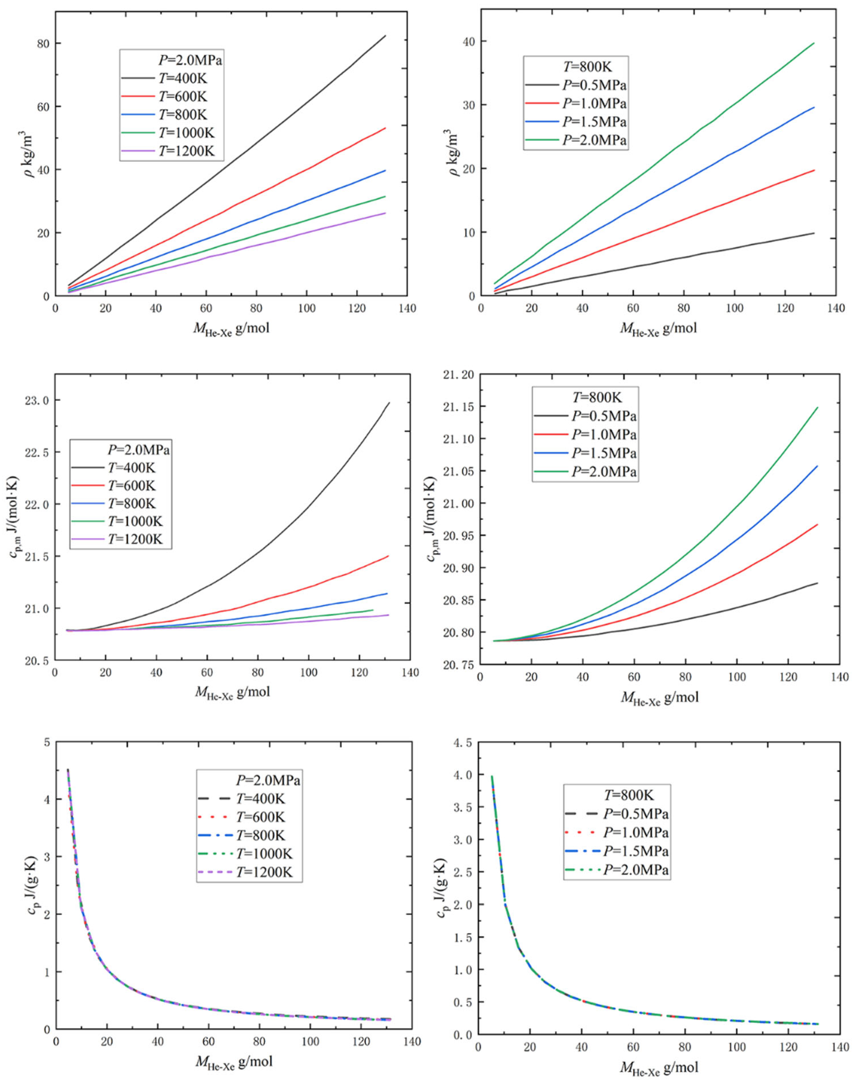
Figure 2 shows the helium–xenon gas mixture’s density and specific heat capacity variation with temperature, pressure, and molar mass. The density of the helium–xenon gas mixture increases linearly with increasing molar mass and pressure, and decreases inversely with increasing temperature, which can be simplified as the ideal gas. As temperature and pressure change, pure helium’s molar specific heat capacity at constant pressure hardly changes, but that of pure xenon changes more significantly; the helium–xenon gas mixture is in between. Overall, the molar specific heat capacity at constant pressure does not vary much with the gas mixture’s temperature, pressure, and molar mass. Since the specific heat capacity at constant pressure is more widely used in engineering, authors convert the molar specific heat capacity at constant pressure to specific heat capacity at constant pressure for analysis. The change of specific heat capacity at constant pressure with temperature and pressure is negligible but significant with the molar mass of the helium–xenon gas mixture, especially when the molar mass is less than 40 g/mol. The smaller the specific heat capacity at constant pressure, the smaller the enthalpy rise of the gas in the compressor, and the less difficult the aerodynamic design of the impeller machinery [17]. In contrast, when the molar mass of the gas exceeds 40 g/mol, the decrease in the specific heat capacity at constant pressure is slight, so it helps little in improving the aerodynamic performance; therefore, the molar mass of the gas mixture should not exceed 40 g/mol.
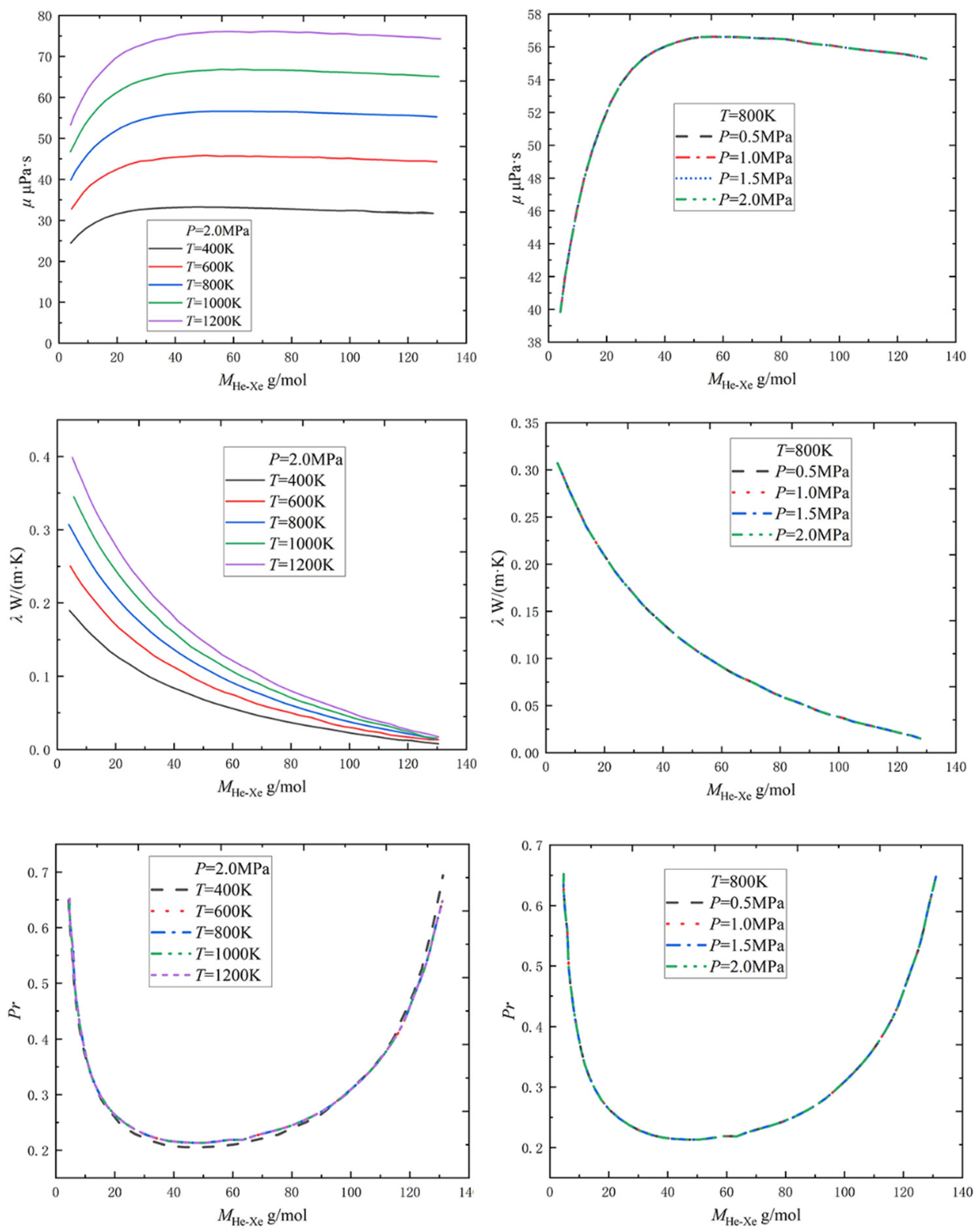
The variation of the dynamic viscosity, thermal conductivity, and Prandtl number of the helium–xenon gas mixture with temperature, pressure, and molar mass of the helium–xenon gas mixture is shown in Figure 3. The dynamic viscosity, thermal conductivity, and Prandtl number characterize the momentum, thermal diffusivity, and the relative size of the gas, respectively. It is easy to see from Figure 3 that all three are insensitive to pressure changes. The dynamic viscosity and thermal conductivity vary proportionally with temperature. The specific heat capacity at constant pressure is insensitive to temperature changes, so the definition of the Prandtl number shows that the Prandtl number is also insensitive to temperature changes. As the molar mass of the helium–xenon gas mixture changes, the dynamic viscosity increases and then stabilizes, the thermal conductivity tends to decrease, and the Prandtl number decreases and then increases. Within most of the range, the helium–xenon gas mixture is in the range of a low Prandtl number (Prandtl = 0.2~0.3).

2.1.2. Relative Heat Transfer Coefficient

Taylor’s correlation [18] can be used to theoretically analyze the relationship between the heat transfer characteristics of helium–xenon mixture and its molar mass. The process is as follows.
Taylor et al. [18] experimentally investigated the heat transfer characteristics of four molar masses of helium–xenon gas mixture in a single tube and gave the Taylor correlation equation based on the experimental results:
N u b = 0.023 Re b 0.8 Pr 0.65 ( T w / T b ) n n = ( 0.57 1.59 / ( x / D ) )
For the above equation, substituting N u = h D / λ , Re = ρ v D / μ , Pr = μ c p / λ and ρ v A = M N ˙ into the Taylor correlation:
h = 0.023 ( T w T b ) n N ˙ 0.8 D 0.2 A 0.8 M 0.8 λ 0.35 c p 0.65 μ 0.15
Thus, under the same momentum conditions (constant N ˙ ), the same geometric conditions (constant cross-sectional area A and equivalent diameter D ), and the same heating conditions (constant ratio of T w and T b ), the convective heat transfer coefficient of the helium–xenon gas mixture in the pipe is related only to its physical parameters, as shown in the following Equation:
h M 0.8 λ 0.35 c p 0.65 μ 0.15
Thus, the relative heat transfer coefficient of the helium–xenon gas mixture concerning pure helium is:
h h H e = ( M M H e ) 0.8 ( λ λ H e ) 0.35 ( c p c p , H e ) 0.65 ( μ μ H e ) 0.15
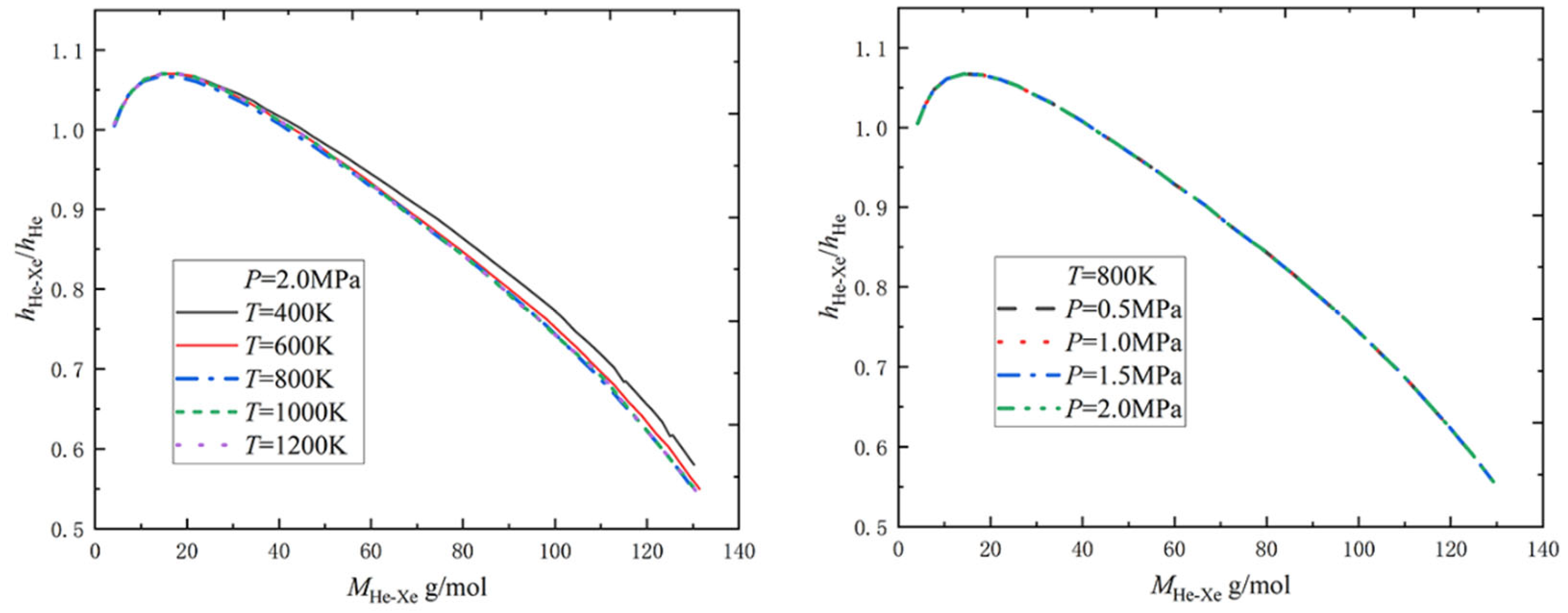
The variation of the physical property parameters of the helium–xenon gas mixture with molar mass has been analyzed in Section 2.1.1. By substituting the parameters at the corresponding points into Equation (7), the variation of the relative heat transfer coefficient with the molar mass of the helium–xenon gas mixture at a specific temperature and pressure can finally be plotted [1,8].
As shown in Figure 4, the relative heat transfer coefficient of the helium–xenon gas mixture concerning pure helium is not very dependent on pressure and temperature. The relative heat transfer coefficient reaches its peak at the molar mass of the gas mixture of 15–20 g/mol, and the value is about 1.07. Therefore, the heat transfer coefficient of the helium–xenon gas mixture of 15–20 g/mol is about 7% higher than that of helium gas under the same conditions. When the molar mass of the helium–xenon gas mixture exceeds about 40 g/mol, the relative heat transfer coefficient is less than 1; that is, the heat transfer coefficient of the helium–xenon gas mixture is less than that of helium gas under the same conditions. As noted in Section 2.1.1, the helium–xenon gas mixture’s aerodynamic performance improves slightly when the molar mass exceeds 40 g/mol. Therefore, considering the helium–xenon gas mixture’s heat transfer and aerodynamics performance, the molar mass should usually be selected in the range of 15~40 g/mol.

2.2. The Effect of Operating Conditions

To investigate operating conditions’ effect on the heat transfer characteristics of the helium–xenon gas mixture, scholars have conducted relevant studies. Their considered factors include the Reynolds number of helium–xenon gas mixture flow in the pipe, inlet temperature and gas velocity, heat flow density outside the pipe heating, etc. The authors of this study now classify the previous studies as follows.

2.2.1. Numerical Model Validation

Before numerical simulation, numerical model verification is required to ensure the accuracy of numerical simulation results. In general, we believe that the experimental data are the most reliable, so we investigated the numerical model validation with the experiment of Taylor [18] as the reference object. Taylor et al. obtained a number of experimental data on the flow and heat transfer of helium–xenon mixture in a circular tube through experimental research. The physical model of Taylor’s experiment is shown in Figure 5, and its physical model parameters are shown in Table 2.
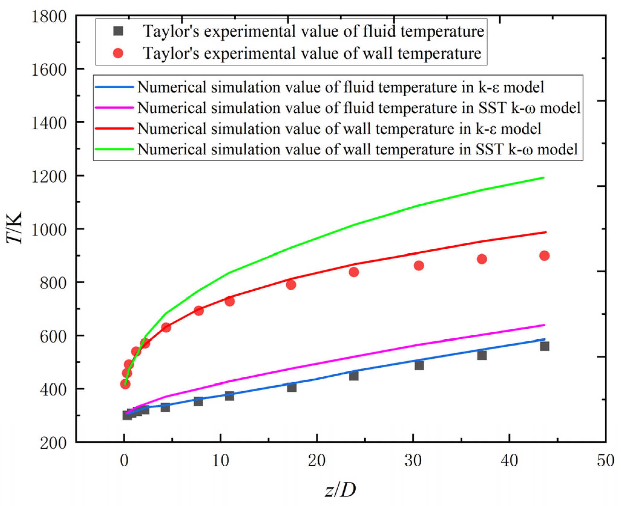
Based on the above Taylor experimental physical model, Chen et al. [19] conducted numerical simulation with a k-ε turbulence model and SST k-ω turbulence model respectively, and compared them with Taylor experimental data. The results are shown in Figure 6. z/D is the ratio of the axial coordinate of the heating section to the inner diameter of the pipe. In general, the numerical simulation values are in good agreement with the experimental values, but due to the existence of the export effect, the error near the outlet is relatively large. When neglecting the experimental section near the outlet, the relative error of k-ε turbulence model is smaller. Therefore, for the flow and heat transfer of helium–xenon mixture, the numerical simulation results obtained by the k-ε turbulence model are more accurate.

2.2.2. Along-Range Distribution of Temperature and Pressure

Sun and Zhang [20] conducted a numerical simulation study on the flow heat transfer characteristics of the helium–xenon gas mixture in the coolant channel of the gas-cooled reactor core, and their experimental model and its model-related parameters are shown in Figure 7 and Table 3.
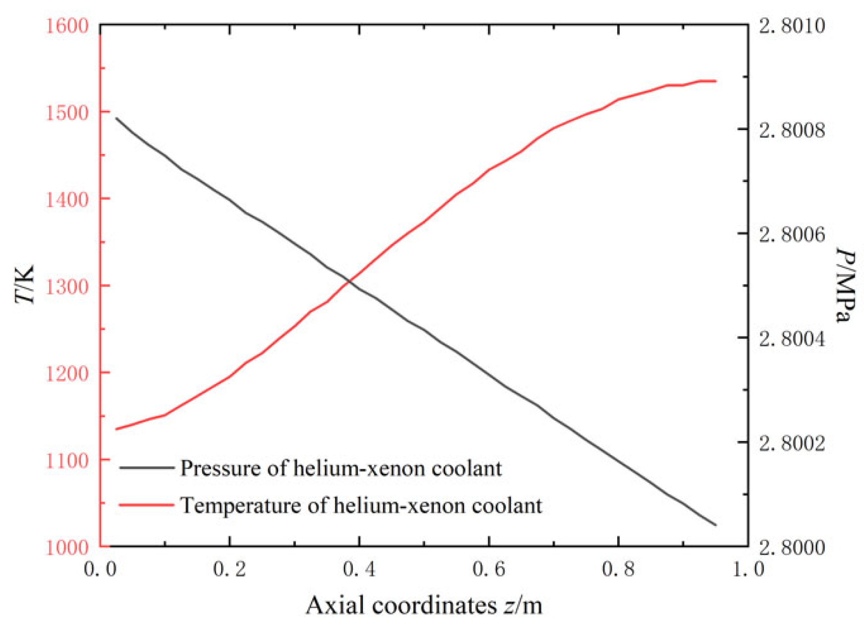
Figure 8 shows the distribution of gas temperature and pressure along the range obtained from the numerical simulation. The pressure decreases linearly, and the temperature increases linearly, except that the temperature growth rate at the inlet and outlet of the coolant channel slows down; the distribution pattern is as expected.

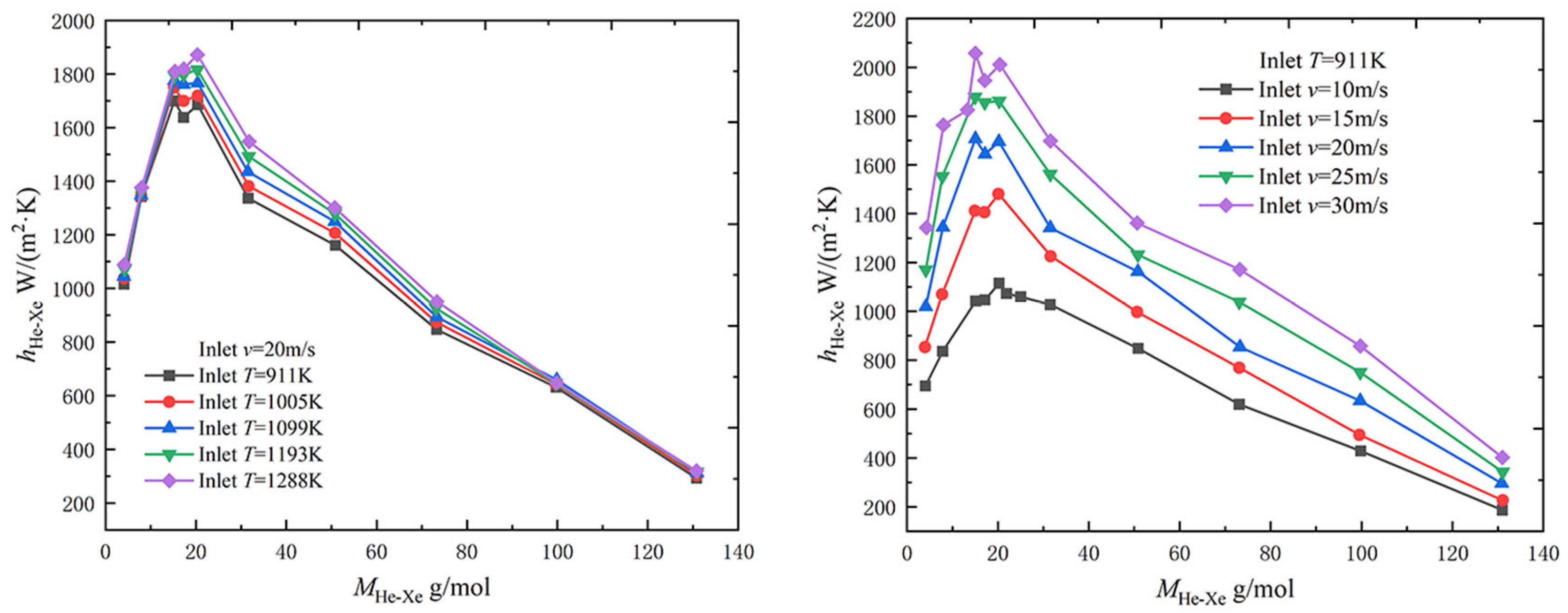
2.2.3. Effect of Inlet Temperature and Velocity

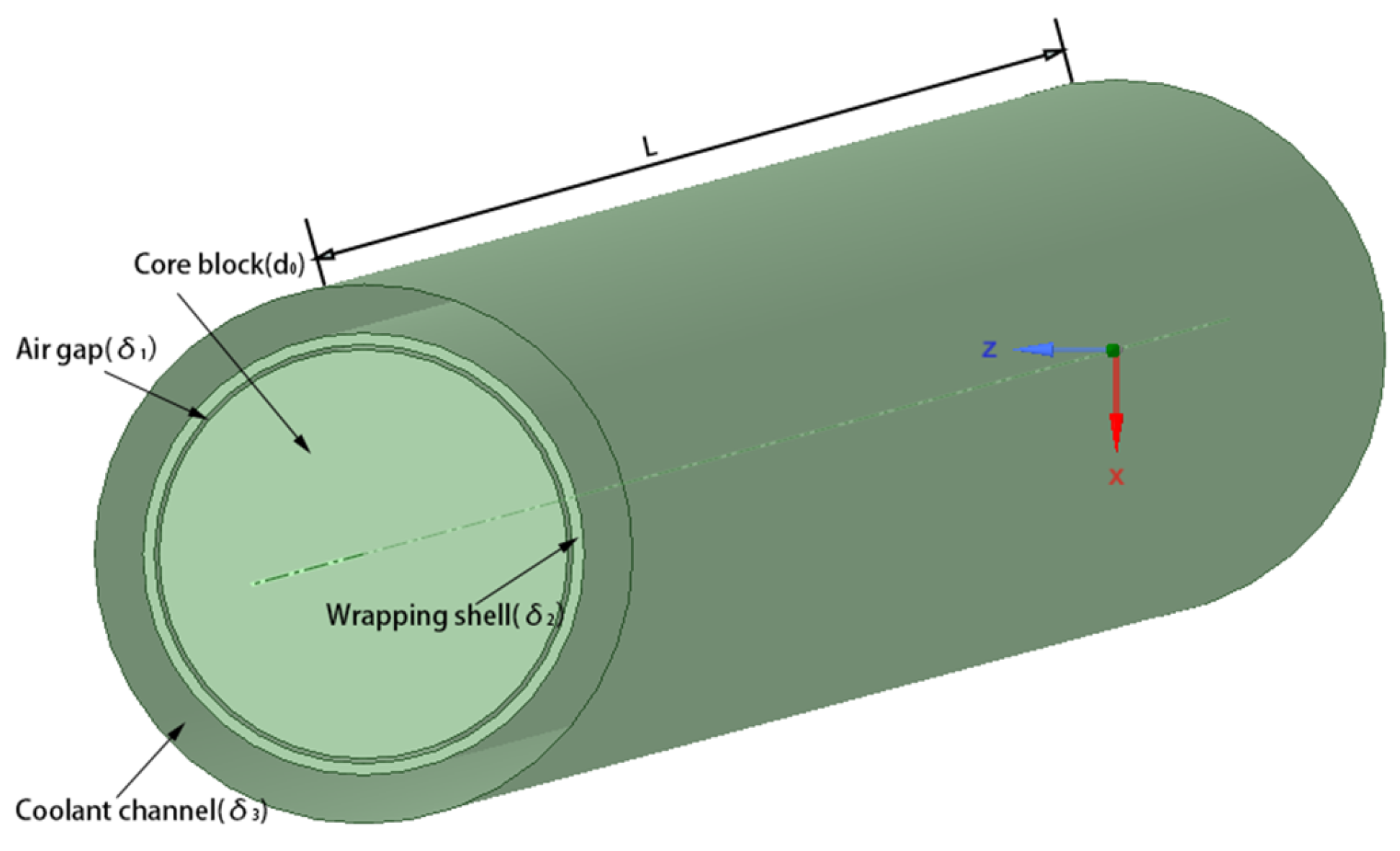
Yu [9] numerically simulated the flow heat transfer characteristics of the helium–xenon gas mixture in the coolant channel of the gas-cooled reactor core. This study focused on the annular coolant channel model, and the model and its model-related parameters are shown in Figure 9 and Table 4.
As shown in Figure 10, the overall trend of the convective heat transfer coefficient with molar mass is consistent with the curve derived using Taylor’s correlation Equation (4) in the previous paper (Figure 4), and the results of the theoretical and numerical simulations corroborate each other. As shown in Figure 10, the convective heat transfer coefficient increases slightly with increasing temperature. As analyzed in Section 2.1.2, the convective heat transfer coefficient is only related to the physical property parameters for the same momentum, geometric, and heating conditions. An increase in the inlet temperature results in heating condition changes, which makes the convective heat transfer coefficient increase; however, at the same time, the temperature increase also makes the physical property parameters change, and the change of dynamic viscosity with temperature is more sensitive than the thermal conductivity, so the change of physical property parameters makes the convective heat transfer coefficient decrease. After combining these two points, the final result is that the convective heat transfer coefficient increases slightly with increasing temperature. As shown in Figure 10, the convective heat transfer coefficient increases with increasing velocity. The cause is that the increasing velocity changes the momentum conditions, the molar flow rate increases, and the turbulence of the gas flow in the tube is enhanced, strengthening the heat transfer. Therefore, the convective heat transfer coefficient increases.

2.2.4. Effect of Reynolds Number and Heating Power Density

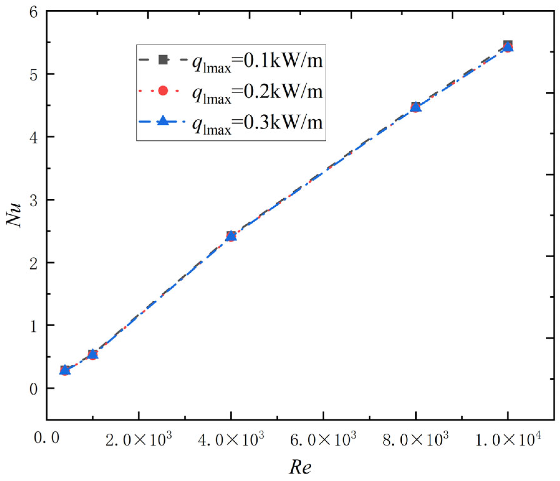
Sun and Zhang [20] numerically simulated the effect of Reynolds number and axial linear power density on heat transfer characteristics. The numerical simulation conditions are shown in Table 5. The average Nusselt number of convective heat transfer of helium–xenon gas mixture in the coolant channel varies with the Reynolds number, and axial linear power density is shown in Figure 11. The average Nusselt number of the helium–xenon coolant in the channel is basically proportional to the Reynolds number, and it is basically constant with the change of the peak axial linear power density q l , max . Therefore, the core size can be minimized by reducing the axial linear power density in a specific temperature range.
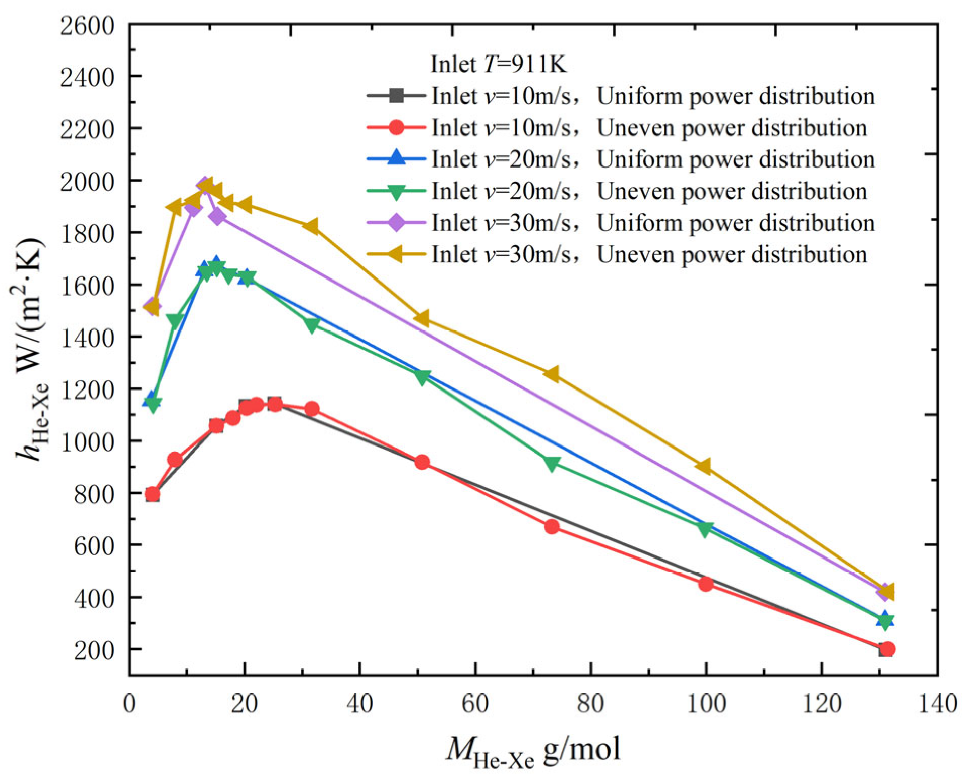
Yu [9] analyzed the effect of heating power density distribution outside the core coolant channel on the heat transfer characteristics of the helium–xenon gas mixture in the channel by numerical simulation. As shown in Figure 12, an uneven distribution uses a cosine heating power distribution with low sides and a high middle; the total power is the same for both uniform and uneven distributions. The results show that the uniformity of the power distribution has little influence on the average convective heat transfer coefficient: the peaks are the same, and the curves with the molar mass of the helium–xenon gas mixture also basically overlap.

2.3. Applicability Verification of Existing Nusselt Number Correlations

Zhou et al. [14,21] studied the applicability of some existing Nusselt number correlations by comparing the experimental values with the prediction data of each correlation formula and then analyzing their prediction accuracy. The relevant correlations involved are shown in Table 6.
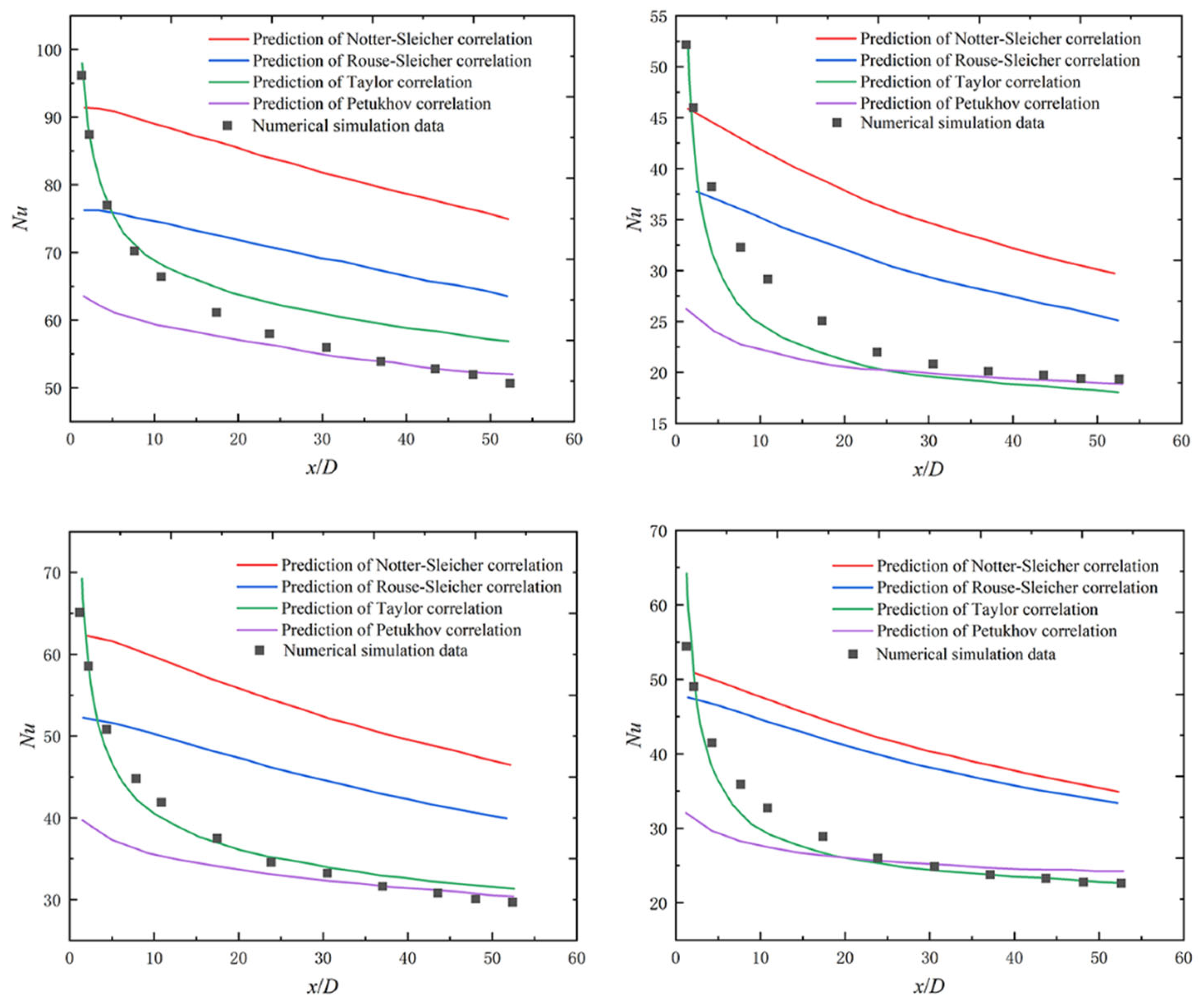
In Table 6, the Dittus–Bolter equation is the constant property correlation, and the correlation Equations (1)–(4) are the variable physical property correlations. When heating the gas in the pipe, the difference in its physical properties in the radial direction in the cross-section is obvious, and the influence of the variable physical properties on the flow heat transfer is not negligible. To study the applicability of the different Nusselt number correlations for helium–xenon gas mixtures, Zhou et al. [14] compared the Nusselt number distributions along the pipe path obtained from numerical simulations with correlations 1–4 in Table 6 for four operating conditions. The main parameters for the four operating conditions are shown in Table 7.
As shown in Figure 13, it can be seen that the local heat transfer coefficient of the helium–xenon gas mixture in the inlet section is large due to the thin thermal boundary layer in the inlet section, then decreases rapidly and gradually stabilizes with the development of the thermal boundary layer. Among the predictions of each correlation, the Taylor correlation [18] has the best fit overall. The Petukhov correlation [22] has a good fit for x/D > 30, but the error is larger in the inlet section because the influence of the inlet section on the heat transfer characteristics is not taken into account. The errors of the remaining two correlations are too significant in all places, and the fit is the worst.
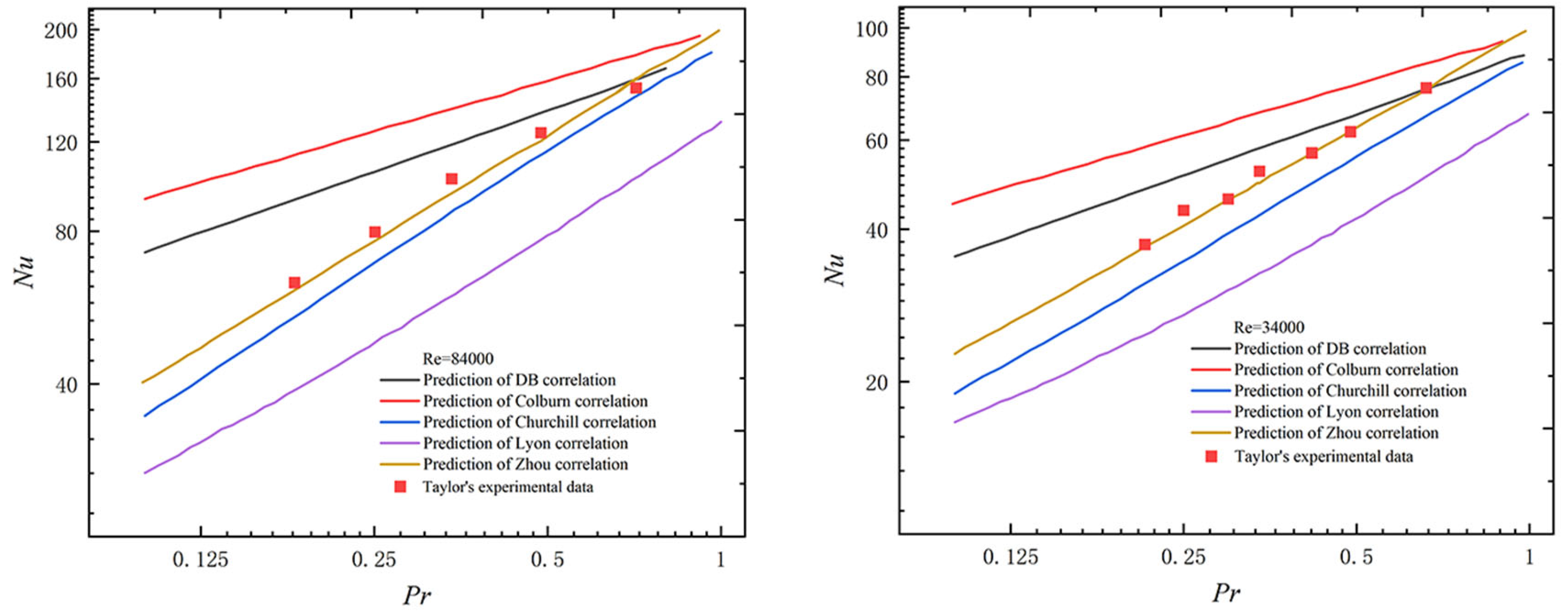
Zhou et al. [21] also analyzed the applicability of existing correlations applicable to different Prandtl number ranges for the helium–xenon gas mixture with low Pr. The heat transfer properties of the helium–xenon gas mixture with a low Prandtl number are different from fluids with medium to high Pr. The specificity of heat transfer in low Pr fluids flow has been widely studied, but the research has mainly focused on liquid metals. The heat transfer of liquid metals is based primarily on molecular heat conduction, while the heat transfer of helium–xenon gas mixture is mainly turbulent convection heat transfer. Due to the differences in their flow heat transfer, the heat transfer correlations of liquid metals cannot be directly recommended for helium–xenon gas mixture, and the applicability of the heat transfer correlations for helium–xenon gas mixtures in a specific Prandtl number range need to be studied in depth. In Table 6, Dittus–Bolter correlations [25] and Colburn correlations [26] are obtained by fitting experimental data from medium and high Prandtl number fluids. Churchill correlations [27] are obtained by fitting experimental data from a more extensive range of Prandtl number fluids. The Lyon correlation [28] is commonly used for liquid metal heat transfer. A new correlation equation was proposed by Zhou et al. through a combination of theoretical derivation and numerical simulation [21]. A Comparison of the above correlations with the Taylor experimental data [18] and the results of the experimental data versus the predicted values of each correlation is shown in Figure 14.
As can be seen in Figure 14, the Dittus–Bolter correlation [25] and the Colburn correlation [26] overestimate the Nusselt number of the helium–xenon gas mixture at low Prandtl; this is because the thermal boundary layer is thicker at a low Prandtl number and the temperature gradient near the wall is small, so the heat transfer properties of the gas are poor. Other correlations underestimate the Nusselt number of the helium–xenon mixture, especially the Lyon correlation [28], and this indicates that there is a non-negligible difference between the molecular heat conduction of liquid metals and the turbulent convective heat transfer properties of the helium–xenon mixture; the heat transfer performance of molecular heat conduction is poorer than that of the turbulent thermal diffusion of the helium–xenon mixture. The Churchill correlation [27] has a relatively good fit at Reynolds number Re = 84,000 but still has a significant error at Re = 34,000. In contrast, the new correlation obtained by Zhou [21] through semi-theoretical derivation fits best with Taylor’s experimental data [18].
In summary, both Taylor’s and Zhou’s correlations have good applicability after the validation by Zhou et al., but both lack a certain amount of experimental data to support them. In order to verify their accuracy and reliability, more experimental data are needed.

3. Enhanced Heat Transfer Technologies

After investigating the heat transfer characteristics of helium–xenon mixture, we should consider how to strengthen the heat transfer, because our ultimate goal is to improve the heat transfer efficiency of helium–xenon mixture in space nuclear power supply. Therefore, the authors investigated the existing literature on enhanced heat transfer technologies.
The authors divided the enhanced heat transfer measures into the following three types: changing the pipe shape, enhancing heat transfer in a single pipe channel, and enhancing heat transfer in a compact heat exchanger.

3.1. Effect of Different Pipe Shapes

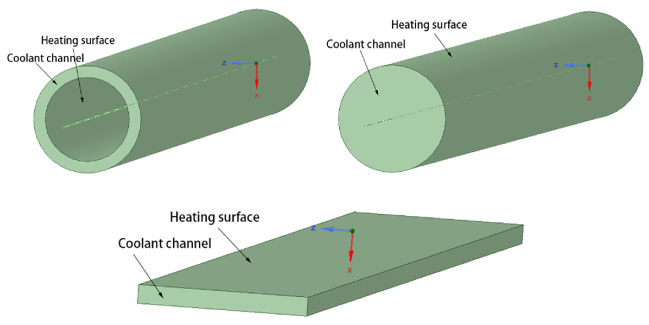
The numerical simulation study of Yu [9] obtained the heat transfer characteristics of the three structural single channels and compared the obtained data. The model plots of these three structural single channels are shown in Figure 15.
As shown in Figure 16, the pressure drop of the helium–xenon gas mixture in the circular coolant channel is much smaller than that in the other two shapes of the channels, with the lowest flow losses and the best flow performance, but its convective heat transfer coefficient is also much smaller than that in the other two channels, with the worst heat transfer performance. The bar bundle coolant channel has the most adequate heat transfer due to its very uneven structure, strong disturbance, intense turbulence, and poor control of radial velocity, but the flow loss is also larger. The heat transfer performance of the annular coolant channel is slightly worse than that of the bar coolant channel, and the pressure drop inside the channel is also higher than that of the bar coolant channel. Therefore, the overall flow heat transfer performance of the annular coolant channel is slightly worse than that of the bar coolant channel.
Huang et al. [29] also performed a numerical simulation of the heat transfer characteristics of a helium–xenon gas mixture in different core coolant channels. The model and related parameters used in the study are shown in Figure 17 and Table 8.
The parameters of the circular coolant channel and the narrow rectangular coolant channel are basically the same as those of the annular channel. The treatment of the different cross-sectional shapes is to control the flow area of the helium–xenon gas mixture to be the same, from which the cross-sectional dimensions of the narrow rectangular channel and the circular channel can be determined.
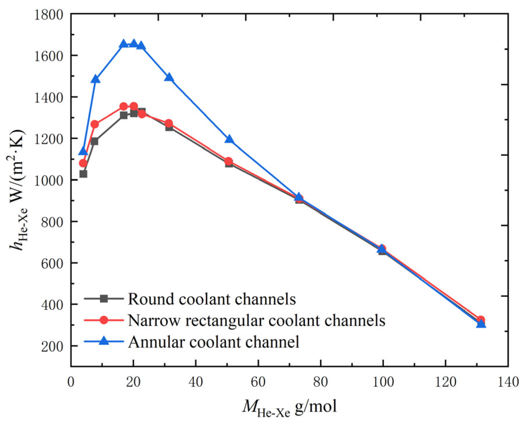
As shown in Figure 18, the numerical simulation study by Huang et al. [29] obtained the same conclusion, that the heat transfer coefficient of circular coolant channels is worse than that of annular coolant channels. Numerical simulation studies of narrow rectangular coolant channels resulted in heat transfer performance that was not much different from circular channels. Both were much worse than the annular coolant channels. In addition, Huang et al. [29] also calculated the equivalent diameters of these three shapes of coolant channels, as shown in Table 9. The smaller the equivalent diameter of the channel type, the larger the convective heat transfer coefficient of the helium–xenon gas mixture inside the channel, so using a channel with a smaller equivalent diameter can improve the heat transfer performance of the helium–xenon gas mixture inside the channel.

3.2. Enhanced Heat Transfer in Single Tube Channel

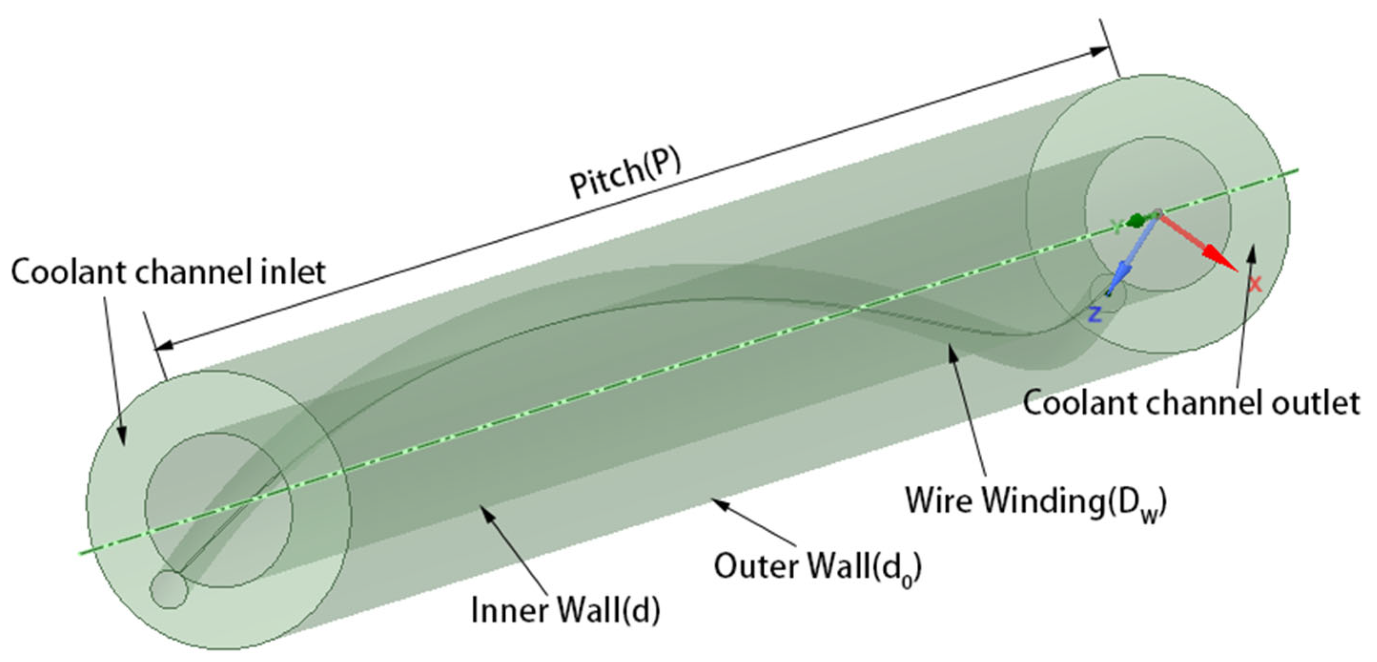
Chen et al. [19] investigated the effect of setting the filament winding structure inside the core circular coolant channel and its different parameters on the heat transfer characteristics of the helium–xenon gas mixture by numerical simulation. The physical model, boundary conditions, and experimental working conditions are shown in Figure 19 and Table 10 and Table 11.
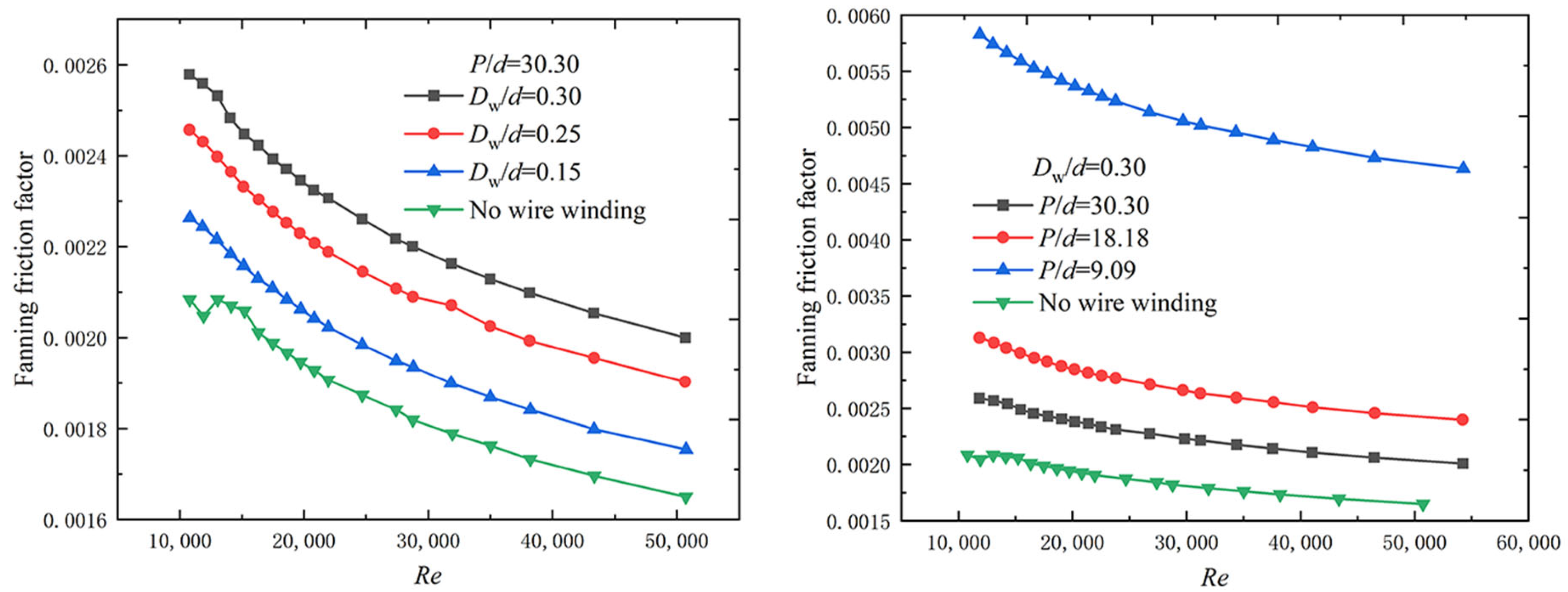
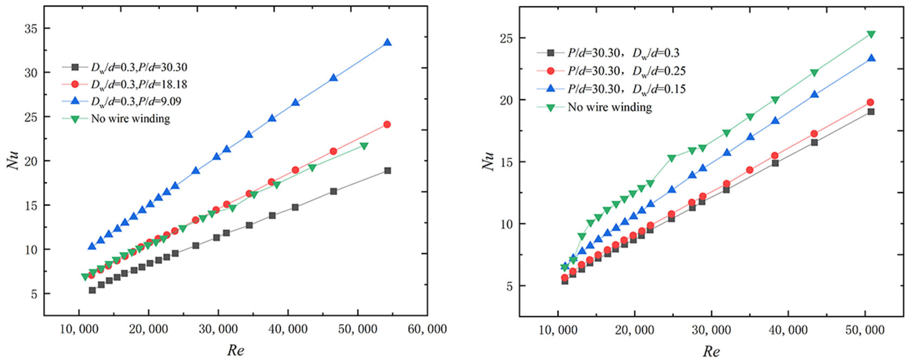
As shown in Figure 20, with the filament winding structure, the Fanning friction factor and the frictional resistance of the helium–xenon gas mixture in the channel both increase. The increase in Reynolds number, which is also an increase in velocity, leads to a decrease in the Fanning friction factor. The larger the filament diameter and the smaller the pitch, the higher the Fanning friction factor due to the more intense disturbance. As shown in Figure 21, the filament winding structure could enhance the convective heat transfer of the helium–xenon gas mixture only under certain conditions. The larger the filament winding pitch and the larger the diameter, the worse the heat transfer characteristics. Under certain filament winding structure conditions, the presence of filament winding will lead to the deterioration of heat transfer characteristics. In the above analysis, smaller diameter and moderate pitch filament winding can fix the fuel rod with filament winding; at the same time, the flow characteristics do not deteriorate too much, and the heat transfer characteristics are slightly enhanced.

3.3. Enhanced Heat Transfer in Compact Heat Exchanger

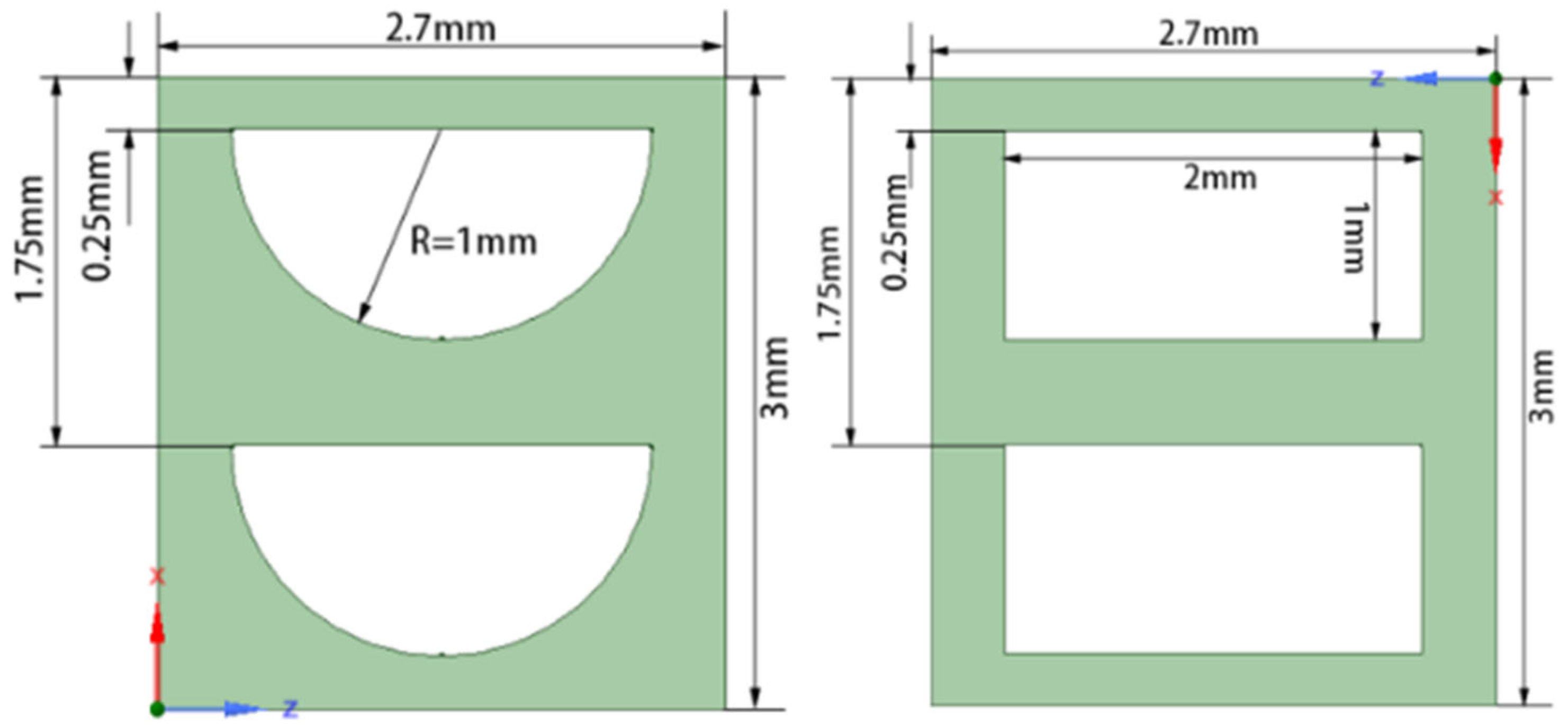
Yang and Huo [30] studied the heat transfer characteristics of high-temperature helium–xenon gas flow in the PCHE (Printed Circuit Heat Exchanger) microchannel using numerical simulations, with a maximum working temperature of about 1000 K. The study showed that the helium–xenon gas mixture has approximately the same heat transfer characteristics in the rectangular cross-section flow channel designed for the fine engraving process and the semicircular cross-section flow channel designed for the etching process. However, the pressure drop of the workpiece in the flow channel of the fine engraving process is 40% smaller than that of the etching process. The mass of the heat return heat exchanger is also reduced by 17%, so the overall performance of the fine engraving process design is better than the etching process. The physical model, initial boundary conditions, and calculation results calculated in the literature are shown in Figure 22 and Table 12 and Table 13. In addition, the literature also investigates the effect of setting up interconnecting channels on the heat transfer characteristics, and the results show that setting up interconnecting channels does not enhance heat transfer.
In summary, there are few studies on the enhanced heat transfer technology for helium–xenon gas mixtures, and the research content is not systematic and in-depth enough to provide a reference for the enhanced heat transfer technology for helium–xenon gas mixtures. In order to promote the research progress, we can refer to more literature related to heat transfer structure to obtain more research ideas [31,32,33].

4. Summary

In summary, experimental and numerical simulation studies of the heat transfer characteristics of helium–xenon gas mixtures are available. However, they are primarily based on simple forms such as circular tubes or single-channel models of the core, and there is a lack of systematic and in-depth studies. There is a lack of research on enhanced heat transfer technologies for helium–xenon gas mixtures. The effectiveness of existing compact heat exchangers (PCHE, plate and fin heat exchangers, original surface heat exchangers, etc.) applied to the helium–xenon gas mixture is still to be verified, due to the special properties of the helium–xenon gas mixture (low Prandtl number). Therefore, future research is urgently needed in the following areas:
(1)
More experimental studies on the heat transfer characteristics of the helium–xenon gas mixture should be carried out. The current research on helium–xenon gas mixtures is mainly based on numerical simulations, and the experimental research is essentially confined to Taylor’s experiment. The model verification data of numerical simulations made by later generations also mainly comes from Taylor’s experiment, so the universality of the research results still needs improvement. At the same time, heat transfer experiments of different structural forms and operating conditions should be carried out to provide more support for designing helium–xenon heat exchangers. In addition, the existing feasible correlation should be further verified and optimized to facilitate the heat transfer calculation of helium–xenon mixture in the future.
(2)
Enhanced heat transfer technologies for helium–xenon gas mixtures should be urgently studied. Compact and efficient helium–xenon heat exchangers are urgently needed to meet the demand for high energy density and miniaturization of space nuclear power sources. This requires detailed analysis of the heat transfer performance of helium–xenon flow, identifying the key factors affecting the heat transfer thermal resistance, corresponding heat transfer enhancement measures to form an optimized design method applicable to helium–xenon heat exchangers, following which an enhanced heat transfer theory of helium–xenon heat exchangers can be developed. In this process, the commonly used enhanced heat transfer structures can provide reference values, such as threaded tubes, finned tubes, and commonly used compact heat exchangers, such as PCHE, plate fin heat exchangers, etc. We can regard these as the beginning of the research on the enhancement of heat transfer of the helium–xenon mixture. It is necessary to carry out a lot of research and obtain a lot of data as soon as possible, and then make further research plans based on the conclusions obtained.

Funding

This study is financially supported by the Science and Technology on Reactor System Design Technology Laboratory and Innovative Scientific Program of CNNC.

Conflicts of Interest

The authors declare no conflict of interest.

References

  1. Wang, Z. Research on Brayton Cycle Properties of Helium-Xenon Mixed Working Fluid Based on Space Nuclear Power System. Master’s Thesis, Harbin Institute of Technology, Harbin, China, 2021. [Google Scholar]
  2. El-Genk, M.S.; Parlos, A.G.; McGhee, J.M.; Lapin, S.; Buden, D.; Mims, J. System design optimization for multimegawatt space nuclear power applications. J. Propuls. Power 1990, 6, 194–202. [Google Scholar] [CrossRef]
  3. El-Genk, M.S. Space nuclear reactor power system concepts with static and dynamic energy conversion. Energy Convers. Manag. 2008, 49, 402–411. [Google Scholar] [CrossRef]
  4. El-Genk, M.S. Deployment history and design considerations for space reactor power systems. Acta Astronaut. 2009, 64, 833–849. [Google Scholar] [CrossRef]
  5. Bennett, G.; Hemler, R.; Schock, A. Space nuclear power: An overview. J. Propuls. Power 1996, 12, 901–910. [Google Scholar] [CrossRef]
  6. Ren, Y. The good space electric power—Space nuclear power reactor. Nucl. Power Eng. 1993, 14, 269–273. [Google Scholar]
  7. Yang, Q.; Lu, H. Research and application of space nuclear reactor power. Spacecr. Eng. 1995, 4, 11–20. [Google Scholar]
  8. Yang, X.; Shi, L. Analysis of Helium-Xenon Mixture Property Influence on Brayton Cycle. At. Energy Sci. Technol. 2018, 52, 1407–1414. [Google Scholar]
  9. Yu, L. Effect of Proportion of Helium-Xenon Mixtures on the Flow and Heat Transfer Tharacteristics in the Coolant Channel of the Reactor. Master’s Thesis, Harbin Engineering University, Harbin, China, 2020. [Google Scholar]
  10. Long, Y. Aerodynamic Design and Performance Research on the High-Loaded Helium Compressor. Master’s Thesis, Harbin Engineering University, Harbin, China, 2012. [Google Scholar]
  11. Dostal, V.; Driscoll, M.J.; Hejzlar, P. A Supercritical Carbon Dioxide Cycle for Next Generation Nuclear Reactors. Mass. Inst. Technol. 2004, 154, 265–282. [Google Scholar]
  12. Bejan, A.; Lorente, S.; Yilbas, B.; Sahin, A. The effect of size on efficiency: Power plants and vascular designs. Int. J. Heat Mass Transf. 2011, 54, 1475–1481. [Google Scholar] [CrossRef]
  13. Gnielinski, V. Neue Gleichungen für den Wärme- und den Stoffübergang in turbulent durchströmten Rohren und Kanälen. Forsch. Im Ing. A 1975, 41, 8–16. [Google Scholar] [CrossRef]
  14. Zhou, B.; Sun, Q.; Sun, J.; Sun, Y. Development and Verification of Calculation Module for He-Xe Flow and Heat Transfer Based on RELAP5. At. Energy Sci. Technol. 2021, 55, 1959–1966. [Google Scholar]
  15. El-Genk, M.S.; Tournier, J.-M. Noble-Gas Binary Mixtures for Closed-Brayton-Cycle Space Reactor Power Systems. J. Propuls. Power 2007, 23, 863–873. [Google Scholar] [CrossRef]
  16. Tournier, J.-M.; El-Genk, M.; Gallo, B. Best estimates of binary gas mixtures properties for closed Brayton cycle space applications. In Proceedings of the 4th International Energy Conversion Engineering Conference and Exhibit (IECEC), San Diego, CA, USA, 26–29 June 2006; p. 4154. [Google Scholar]
  17. Li, Z.; Yang, X.; Wang, J.; Zhang, Z. Thermodynamic analysis of a Brayton cycle system for a space power reactor. J. Tsinghua Univ. (Sci. Technol.) 2017, 57, 537–543+549. [Google Scholar]
  18. Taylor, M.; Bauer, K.; McEligot, D. Internal forced convection to low-Prandtl-number gas mixtures. Int. J. Heat Mass Transf. 1988, 31, 13–25. [Google Scholar] [CrossRef]
  19. Chen, S.; Qin, H.; Wang, C.; Zhang, Y.; Zhang, D.; Qiu, S.; Tian, W.; Su, G. Flow and Heat Transfer Characteristic of He-Xe Gas Mixture with Helical Wire Structure. At. Energy Sci. Technol. 2021, 55, 991–999. [Google Scholar]
  20. Sun, Q.; Zhang, H. Numerical study on heat transfer performance of cooling channels in space core. Appl. Therm. Eng. 2022, 210, 118274. [Google Scholar] [CrossRef]
  21. Zhou, B.; Ji, Y.; Sun, J.; Sun, Y.-L. Nusselt number correlation for turbulent heat transfer of helium–xenon gas mixtures. Nucl. Sci. Tech. 2021, 32, 128. [Google Scholar] [CrossRef]
  22. Petukhov, B.S. Heat Transfer and Friction in Turbulent Pipe Flow with Variable Physical Properties. Adv. Heat Transf. 1970, 6, 503–564. [Google Scholar]
  23. Sleicher, C.; Rouse, M. A convenient correlation for heat transfer to constant and variable property fluids in turbulent pipe flow. Int. J. Heat Mass Transf. 1975, 18, 677–683. [Google Scholar] [CrossRef]
  24. Notter, R.; Sleicher, C. A solution to the turbulent Graetz problem—III Fully developed and entry region heat transfer rates. Chem. Eng. Sci. 1972, 27, 2073–2093. [Google Scholar] [CrossRef]
  25. Dittus, F.; Boelter, L. Heat transfer in automobile radiators of the tubular type. Int. Commun. Heat Mass Transf. 1985, 12, 3–22. [Google Scholar] [CrossRef]
  26. Colburn, A.P. A method of correlating forced convection heat-transfer data and a comparison with fluid friction. Int. J. Heat Mass Transf. 1964, 7, 1359–1384. [Google Scholar] [CrossRef]
  27. Churchill, S.W. Comprehensive Correlating Equations for Heat, Mass and Momentum Transfer in Fully Developed Flow in Smooth Tubes. Ind. Eng. Chem. Fundam. 1977, 16, 109–116. [Google Scholar] [CrossRef]
  28. Lyon, R.N. Liquid metal heat-transfer coefficients. Chem. Eng. Prog. 1951, 47, 75–79. [Google Scholar]
  29. Huang, D.; Li, Z.; Yu, L.; He, X.; Zhao, F.; Tan, S. Influence of helium-xenon mixing ratio on flow heat transfer characteristics of reactor channels. J. Harbin Eng. Univ. 2021, 42, 745–750. [Google Scholar]
  30. Yang, Y.; Huo, H. Analysis of Heat Transfer and Flow Characteristic for High Temperature Helium-xenon Gas Microchannel Regenerator. At. Energy Sci. Technol. 2018, 52, 2156–2163. [Google Scholar]
  31. Huang, Y.; Xiao, X.; Kang, H.; Lv, J.; Zeng, R.; Shen, J. Thermal management of polymer electrolyte membrane fuel cells: A critical review of heat transfer mechanisms, cooling approaches, and advanced cooling techniques analysis. Energy Convers. Manag. 2022, 254, 115–221. [Google Scholar] [CrossRef]
  32. Chen, H.; Ruan, X.-H.; Peng, Y.-H.; Wang, Y.-L.; Yu, C.-K. Application status and prospect of spray cooling in electronics and energy conversion industries. Sustain. Energy Technol. Assess. 2022, 52, 102–181. [Google Scholar] [CrossRef]
  33. Bhandari, P.; Prajapati, Y. Influences of tip clearance on flow and heat transfer characteristics of open type micro pin fin heat sink. Int. J. Therm. Sci. 2022, 179, 107–714. [Google Scholar]
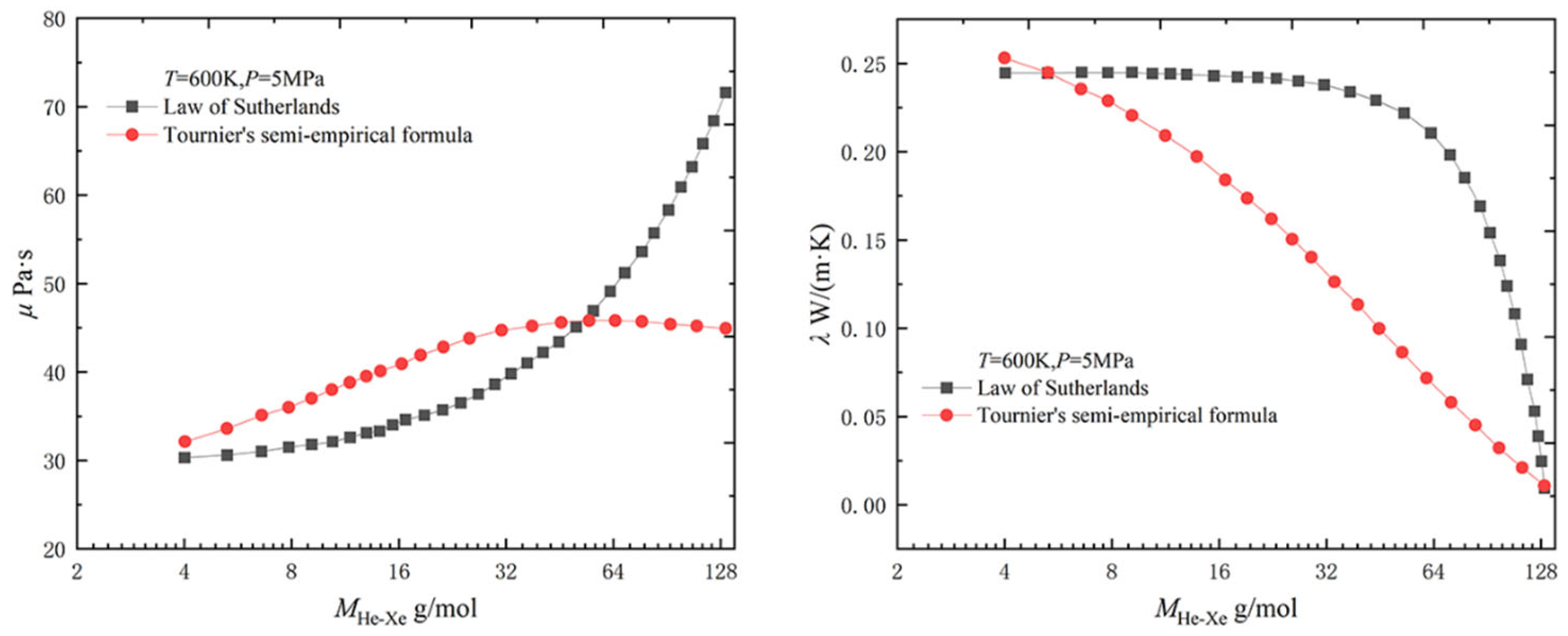
Figure 1. Comparison of Sutherland’s law and Tournier’s semi-empirical formulas for prediction of dynamic viscosity and thermal conductivity [14].
Energies 16 00068 g001
Figure 2. Variation of thermodynamic properties of helium–xenon gas mixture with molar mass of helium–xenon gas mixture [1,8].
Energies 16 00068 g002
Figure 3. Variation of transport properties of helium–xenon gas mixture with molar mass of helium–xenon gas mixture [1,8].
Energies 16 00068 g003
Figure 4. Relative heat transfer coefficient of the helium–xenon gas mixture [1,8].
Energies 16 00068 g004
Figure 5. The physical model of Taylor’s experiment [18].
Energies 16 00068 g005
Figure 6. Numerical model validation by Chen et al. [19].
Energies 16 00068 g006
Figure 7. The numerical simulation model of Sun and Zhang [20].
Energies 16 00068 g007
Figure 8. Pressure and temperature distribution of helium–xenon coolant in the channel [20].
Energies 16 00068 g008
Figure 9. Single-channel model for numerical simulation by Yu [9].
Energies 16 00068 g009
Figure 10. Effect of variation of inlet temperature and velocity on convective heat transfer coefficient of the helium–xenon gas mixture [9].
Energies 16 00068 g010
Figure 11. Variation of helium–xenon coolant convective heat transfer average Nusselt number in the channel with Re versus axial linear power density [20].
Energies 16 00068 g011
Figure 12. Variation of convective heat transfer coefficient of the helium–xenon gas mixture in the channel with the fuel rod’s heating power distribution [9].
Energies 16 00068 g012
Figure 13. Verification of the applicability of variational Nusselt number correlations [14].
Energies 16 00068 g013
Figure 14. Validation of correlations applicable to different Prandtl number ranges [22].
Energies 16 00068 g014
Figure 15. Three models for the numerical simulation of Yu [9].
Energies 16 00068 g015
Figure 16. Pressure drop and heat transfer coefficient of the helium–xenon gas mixture in channels of different shapes [9].
Energies 16 00068 g016
Figure 17. The model used in the numerical simulation study by Huang et al. [29].
Energies 16 00068 g017
Figure 18. Variation of convective heat transfer coefficient with channel shape in the coolant channel for helium–xenon gas mixture [29].
Energies 16 00068 g018
Figure 19. Physical model for numerical simulation of Chen et al. [19].
Energies 16 00068 g019
Figure 20. Variation of Fanning friction factor with filament winding parameters [19].
Energies 16 00068 g020
Figure 21. Variation of Nusselt number with wire winding parameters [19].
Energies 16 00068 g021
Figure 22. PCHE model for numerical simulation of the fine engraving process and etching process by Yang and Huo [30].
Energies 16 00068 g022
Table 1. The semi-empirical formula for calculating the physical property parameters of binary mixture rare gases proposed by Tournier et al. [16].
ParameterFormula
Specific heat capacity c c ^ p = c ^ p 0 + ρ ^ R [ B T d B d T T 2 d 2 B d T 2 + ρ ^ ( C T 2 2 d 2 C d T 2 ) ] + R T [ B T d B d T + ρ ^ ( 2 C T d C d T ) ] ( ρ ^ T ) p c ^ p 0 = 5 2 R , c p = c ^ p / M , ( ρ ^ T ) p = ( ρ ^ + B ρ ^ 2 + C ρ ^ 3 ) / T + d B d T ρ ^ 2 + d C d T ρ ^ 3 1 + 2 B ρ ^ + 3 C ρ ^ 2
Density ρ p = R T ρ ^ Z = R T ρ ^ ( 1 + B ρ ^ + C ρ ^ 2 ) ρ ( T , p , x 1 ) = M ρ ^ , M = x 1 M 1 + x 2 M 2
Dynamic Viscosity μ μ ( T , p , x 1 ) = μ 0 ( T ) + 0.565 x 1 μ 1 * ψ μ 0.291 V * ¯ M ρ μ 1 * = 0.204 × 10 7 M 1 T 1 * ( 0.291 V * ¯ ) 0.667 ψ μ ( r ) = 0.221 r + 1.062 r 2 0.509 r 3 + 0.225 r 4
Thermal conductivity λ λ ( T , p , x 1 ) = λ 0 ( T ) + 0.66 λ * ψ λ 0.291 V * ¯ M ρ λ * = 0.304 × 10 4 T * ¯ 0.277 M 0.465 ( 0.291 V * ¯ ) 0.415 ψ λ ( r ) = 0.645 r + 0.33 r 2 + 0.0368 r 3 0.0128 r 4
Table 2. The physical model parameters of Taylor’s experiment [18].
ParameterValue
d/mm0.00587
δ/mm0.00056
L1/mm328.72
L2/mm352.2
Table 3. The parameters of the numerical simulation model of Sun and Zhang [20].
ParameterValue/Formula
L/m0.985
κ /mm−10.08932
q l /kW/m q l = q l , max sin ( 3.19 Z )
Table 4. The parameters of the numerical simulation model of Yu [9].
ParameterValue
d1/m0.01819
δ 1 / m 0.00022
δ 2 / m 0.00051
δ 3 / m 0.00216
L/m0.608
P/W3480
Table 5. Working conditions of the numerical simulation by Sun and Zhang [20].
Reql,max
kW/m
G
kg/s
v
m/s
Tin
K
pout
MPa
4000.1/0.2/0.39.9605 × 10−51.57871136.42.8
10000.1/0.2/0.32.4901 × 10−43.94671136.42.8
40000.1/0.2/0.39.9605 × 10−415.78681136.42.8
80000.1/0.2/0.31.9921 × 10−331.57371136.42.8
10,0000.1/0.2/0.32.4901 × 10−339.46751136.42.8
Table 6. Existing Nusselt number correlations.
Serial NumberNameFormulaRange of Application
1Petukhov [22] N u b = N u 0 ( T W / T b ) n N u 0 = ( ζ / 8 ) Re Pr 1.07 + 12.7 ζ / 8 ( Pr 2 / 3 1 ) ζ = ( 1.82 lg Re 1.64 ) 2 n = 0.3 lg ( T W / T b ) 0.36 104Re ≤ 5 × 10⁶
2Sleicher and Rouse [23] N u b = N u 0 ( T W / T b ) n N u 0 = ( ζ / 8 ) Re Pr 1.07 + 12.7 ζ / 8 ( Pr 2 / 3 1 ) ζ = ( 1.82 lg Re 1.64 ) 2 n = lg ( T W / T b ) 0.25 + 0.3 104Re ≤ 5 × 10⁶
3Notter and Sleicher [24] N u b = 5 + 0.012 Re b 0.83 ( Pr + 0.29 ) ( T W / T b ) n n = lg ( T W / T b ) 0.25 + 0.3 104Re ≤ 5 × 10⁶
1 < Tw/Tb < 5
4Taylor [18] N u b = 0.023 Re b 0.8 Pr 0.65 ( T W / T b ) n n = ( 0.57 1.59 / ( x / D ) ) 1.8 × 10⁴Re ≤6 × 10⁴
Tw/Tb < 2
5Dittus and Bolter [25] N u = 0.023 Re 0.8 Pr 0.4 0.7 ≤ Pr ≤ 120
104Re ≤ 1.2 × 10⁵
6Colburn [26] N u = 0.023 Re 0.8 Pr 1 / 3 0.5 ≤ Pr ≤ 100
7Churchill [27] N u = 6.3 + 0.079 Re f Pr ( 1 + Pr 0.8 ) 5 / 6 1 / f = 2.21 ln ( Re / 7 ) 0.001 ≤ Pr ≤ 200
8Lyon [28] N u = 7.0 + 0.025 ( Pr Re / 2 ) 0.8 Pr < 0.1
9Zhou [21] N u b = 0.20 Pr Re 0.875 4.53 Re 0.125 + 11.83 Pr 0.45 + 1.18 ln Pr 10.05 ( T W T b ) 0.63 1.8 × 10⁴Re ≤6 × 10⁴
0.21 ≤ Pr ≤ 0.30
Tw/Tb < 2
Table 7. Working conditions of the numerical simulation by Zhou et al. [14].
ParameterCondition 1Condition 2Condition 3Condition 4
MHe-Xe/g/mol83.839.528.314.5
Pr0.250.210.230.30
Re63,987~85,80219,174~36,18334,443~53,39019,485~34,042
q/W/m243,637136,770157,094296,622
G/kg/(m2·s)350.6156.4229.1139.7
Pout/Pa471,502563,474928,019806,581
Table 8. Parameters of the annular coolant channel model [29].
ParameterValue
dout/mm19.65
δ/mm2.16
L/mm1118
Tin/K882
Tout/K1125
vin/m/s20
Pin/MPa2
Pout/MPa1.991
Table 9. Comparison of the equivalent diameters (de) of the three coolant channels [29].
Types of Coolant ChannelsS/10−4 m2de/mm
Annular coolant channel1.484.32
Circular coolant channels1.4813.39
Narrow rectangular coolant channels1.487.22
Table 10. Boundary conditions for the numerical simulation of Chen et al. [19].
ParameterValue
Tout/K<1200
Tw/K<1800
q/kW/m260
vin/m/s10~27
p/MPa1.5~2.5
Table 11. Working conditions of the numerical simulation of Chen et al. [19].
ConditionsP/dDw/dd0/d
Condition 130.300.31.8
Condition 218.180.31.8
Condition 39.090.31.8
Condition 430.300.251.8
Condition 530.300.151.8
Table 12. Boundary conditions for single-channel heat transfer calculations by Yang and Huo [30].
ParameterValue
G/g/s0.2125
Thot,in/K961
Tcold,in/K516
Phot,in/MPa1.15
Pcold,in/MPa2.1
L/mm390
Table 13. Results for single-channel heat transfer calculations by Yang and Huo [30].
ParameterFine Engraving ProcessEtching Process
Thot,out/K572.2571.6
Tcold,out/K905905.8
vhot,in/m/s18.323.2
vcold,in/m/s11.014.1
ΔPhot/Pa750812,574.8
ΔPcold/Pa44917472
Disclaimer/Publisher’s Note: The statements, opinions and data contained in all publications are solely those of the individual author(s) and contributor(s) and not of MDPI and/or the editor(s). MDPI and/or the editor(s) disclaim responsibility for any injury to people or property resulting from any ideas, methods, instructions or products referred to in the content.