
A Review on Heat Transfer Characteristics and Enhanced Heat Transfer Technology for Helium–Xenon Gas Mixtures

Abstract
:1. Introduction
2. Heat Transfer Characteristics
2.1. The Effect of Helium–Xenon Mixing Ratio
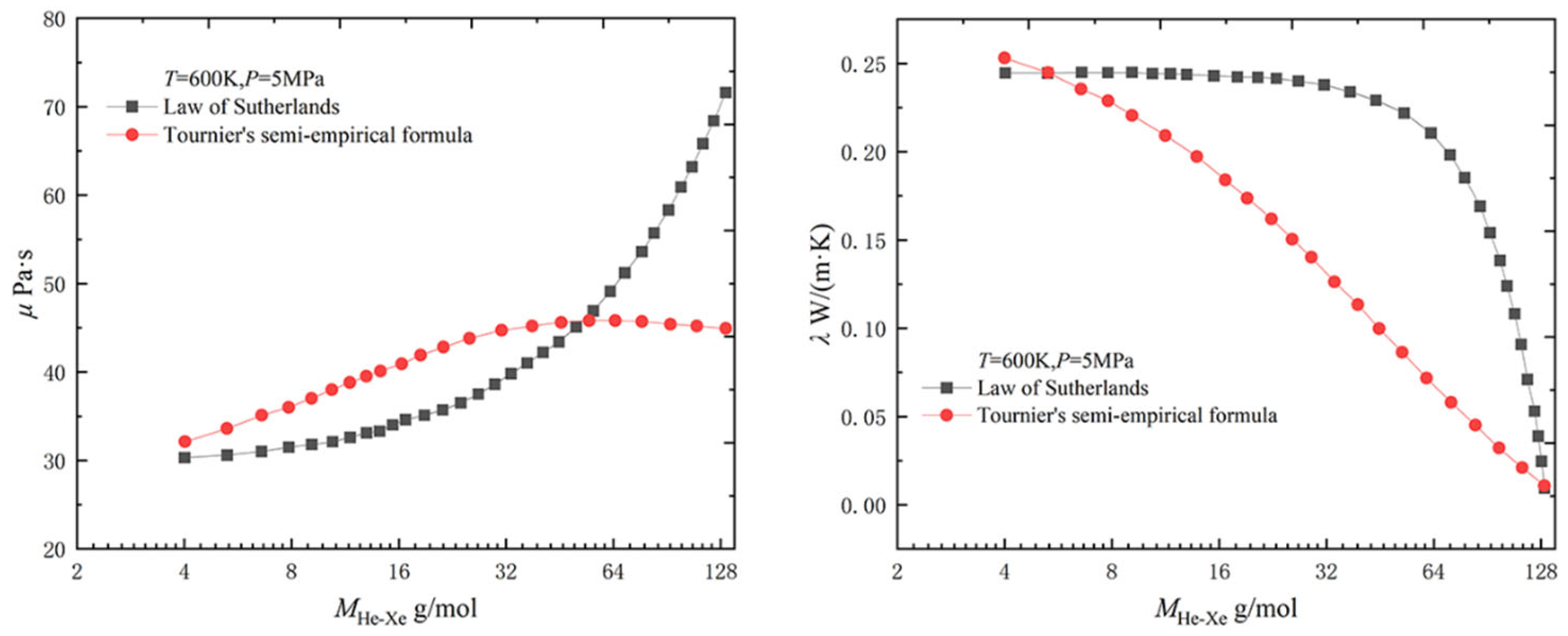
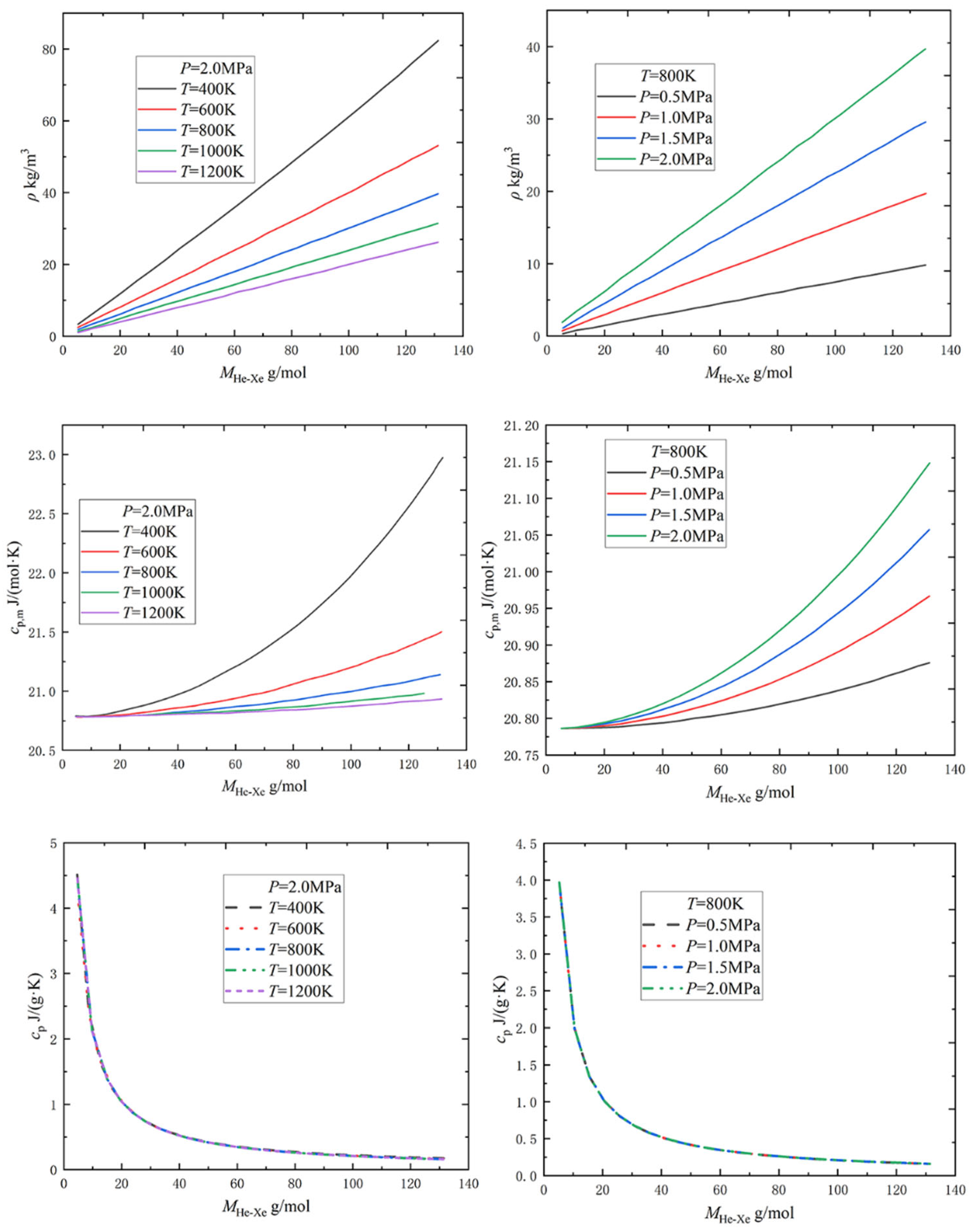
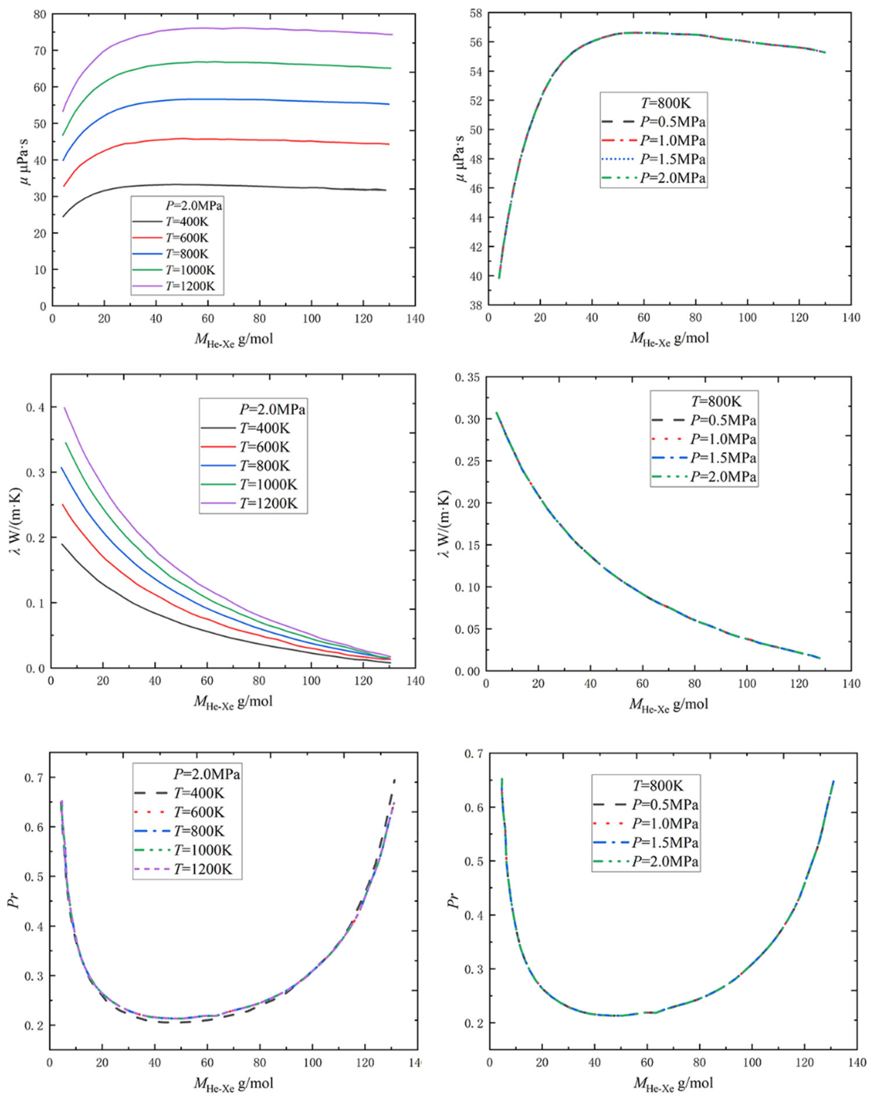
2.1.1. Physical Property Parameters
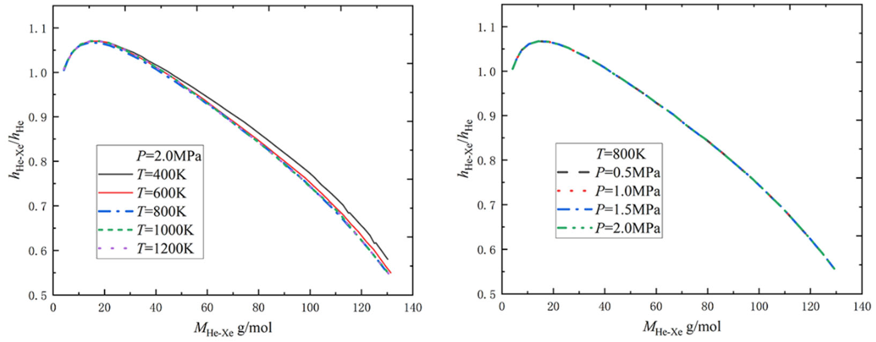
2.1.2. Relative Heat Transfer Coefficient
2.2. The Effect of Operating Conditions
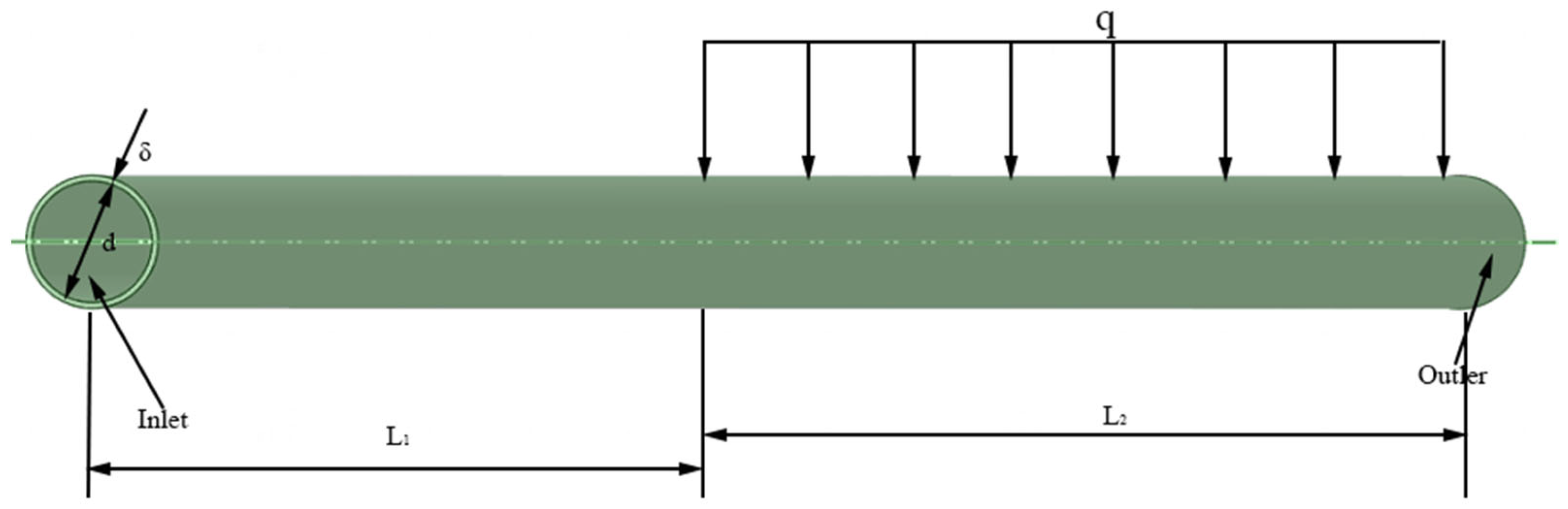
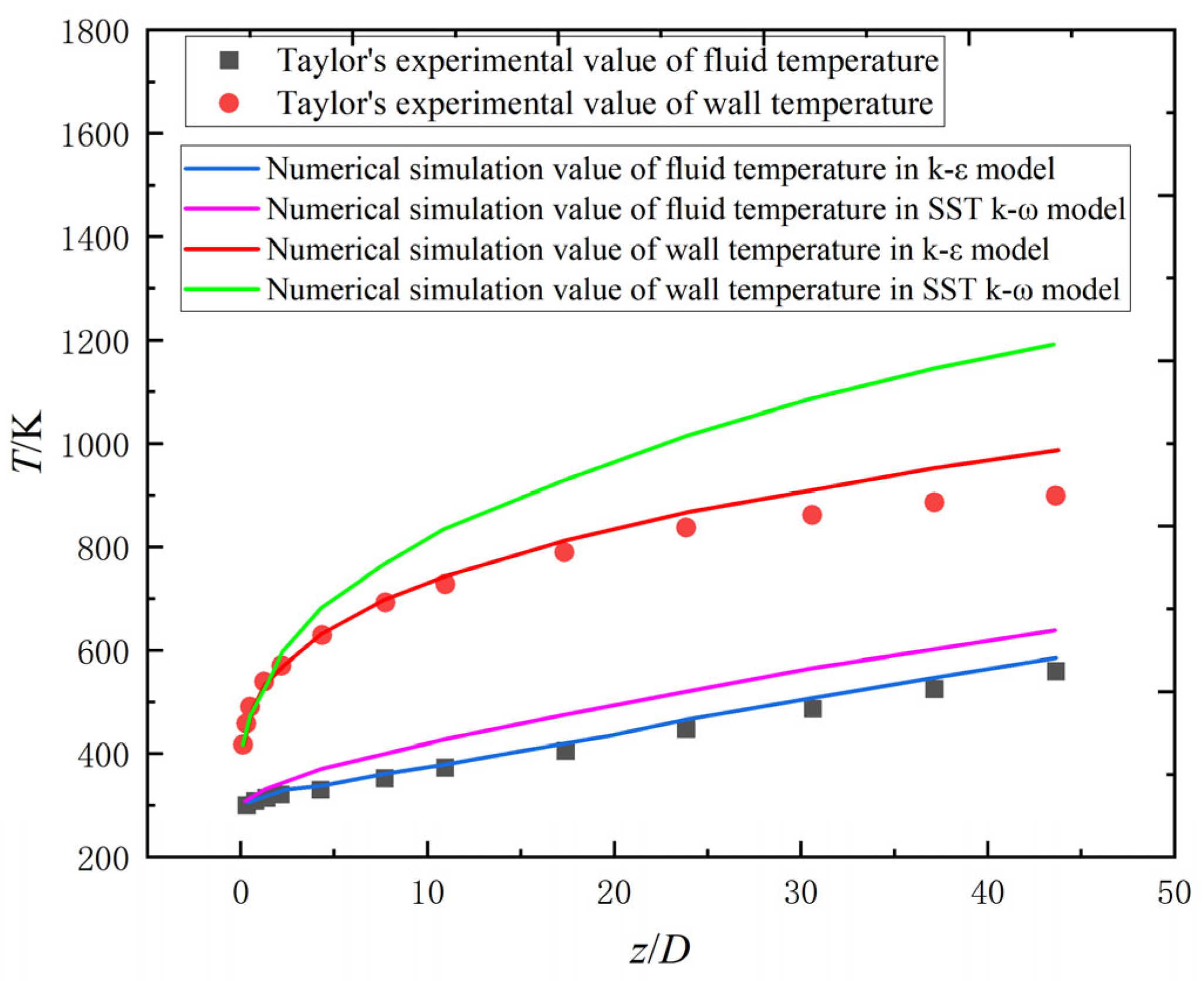
2.2.1. Numerical Model Validation
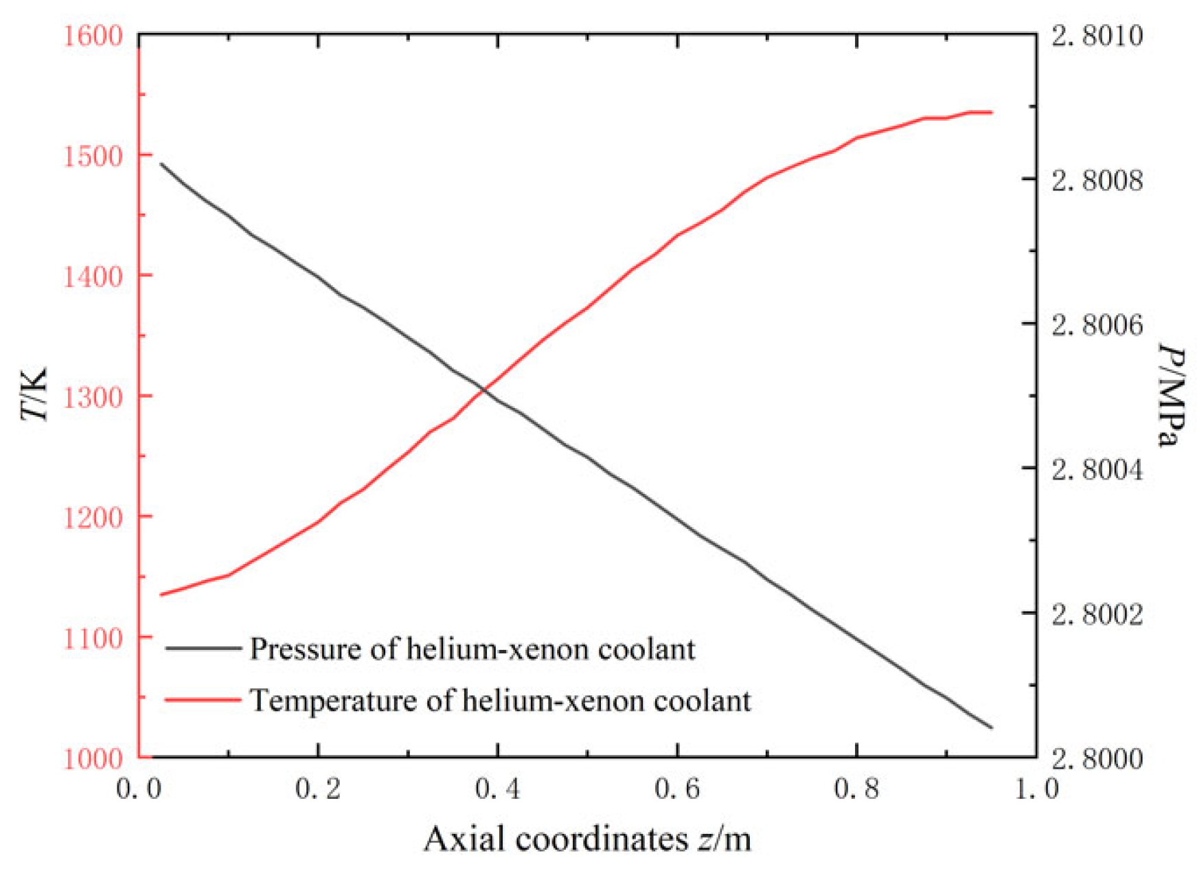
2.2.2. Along-Range Distribution of Temperature and Pressure
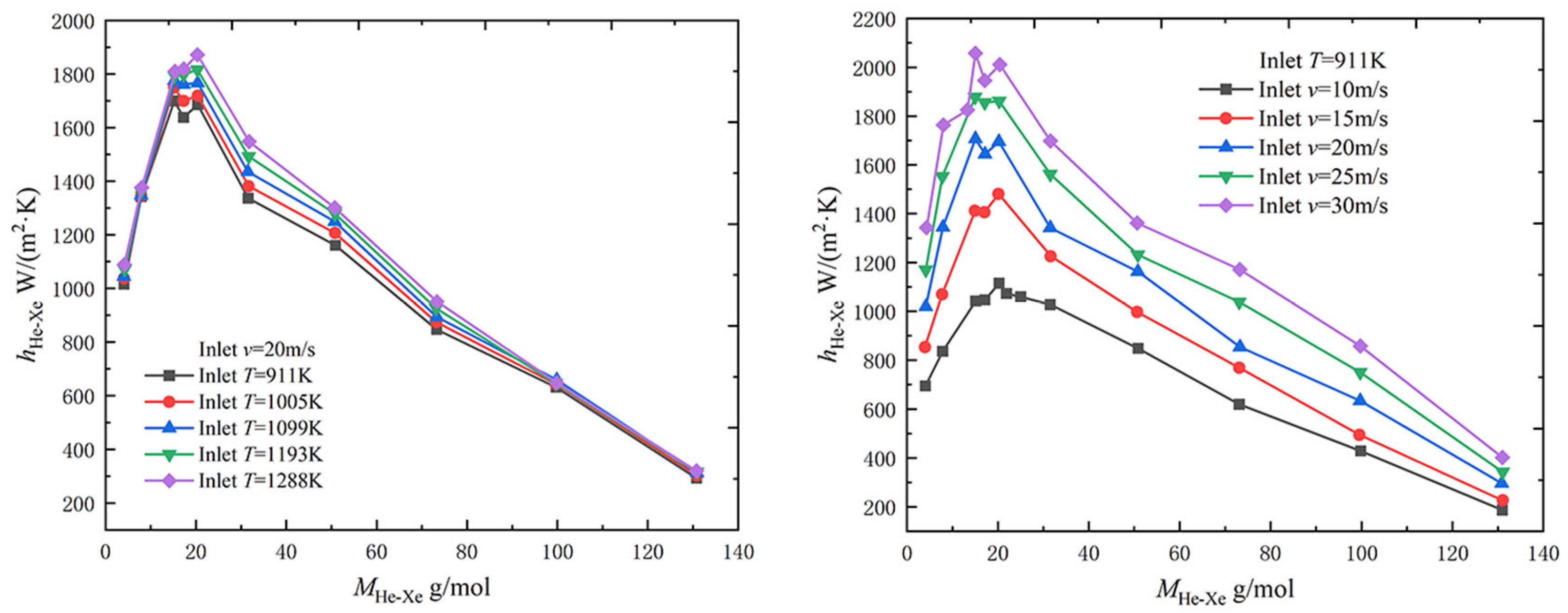
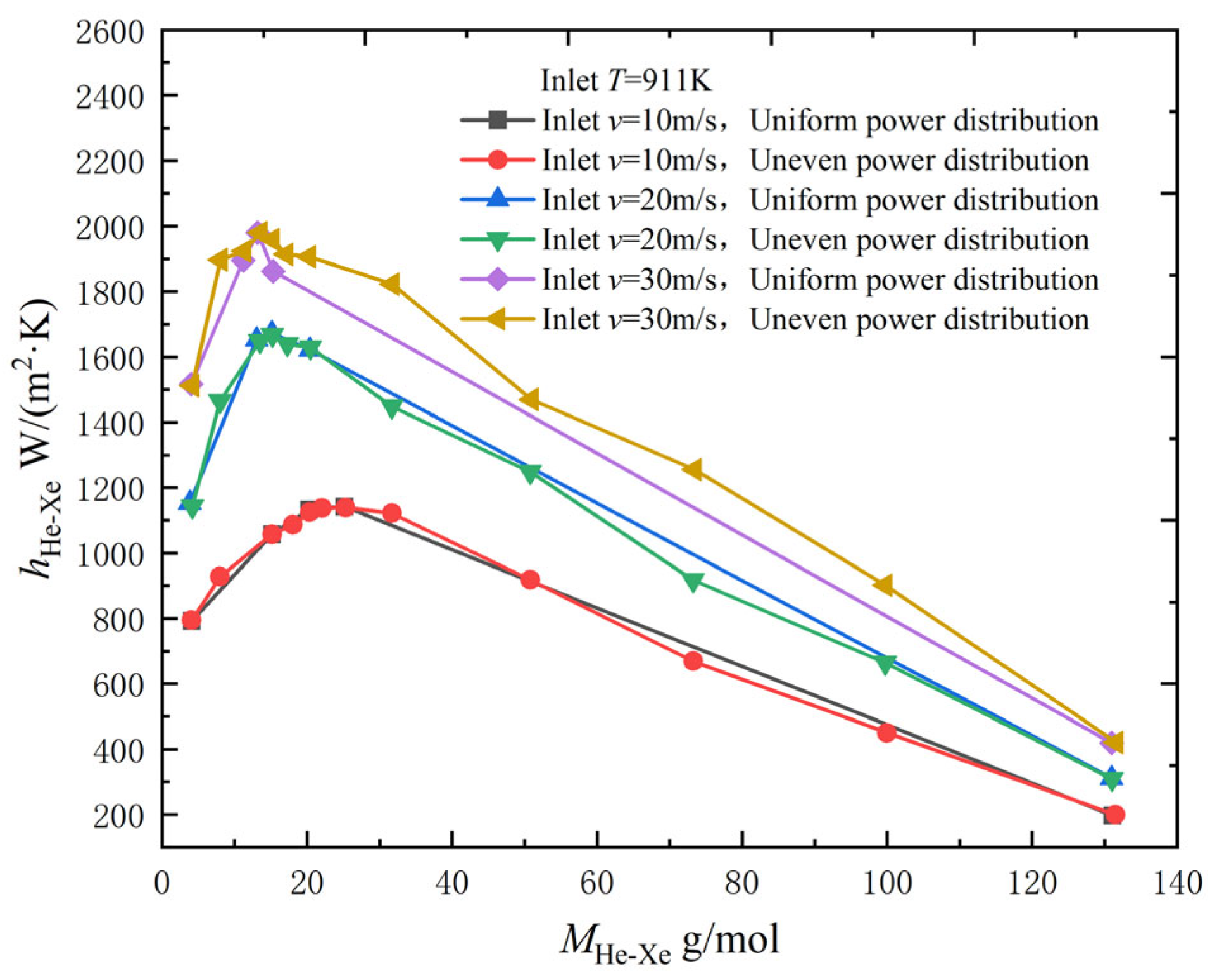
2.2.3. Effect of Inlet Temperature and Velocity
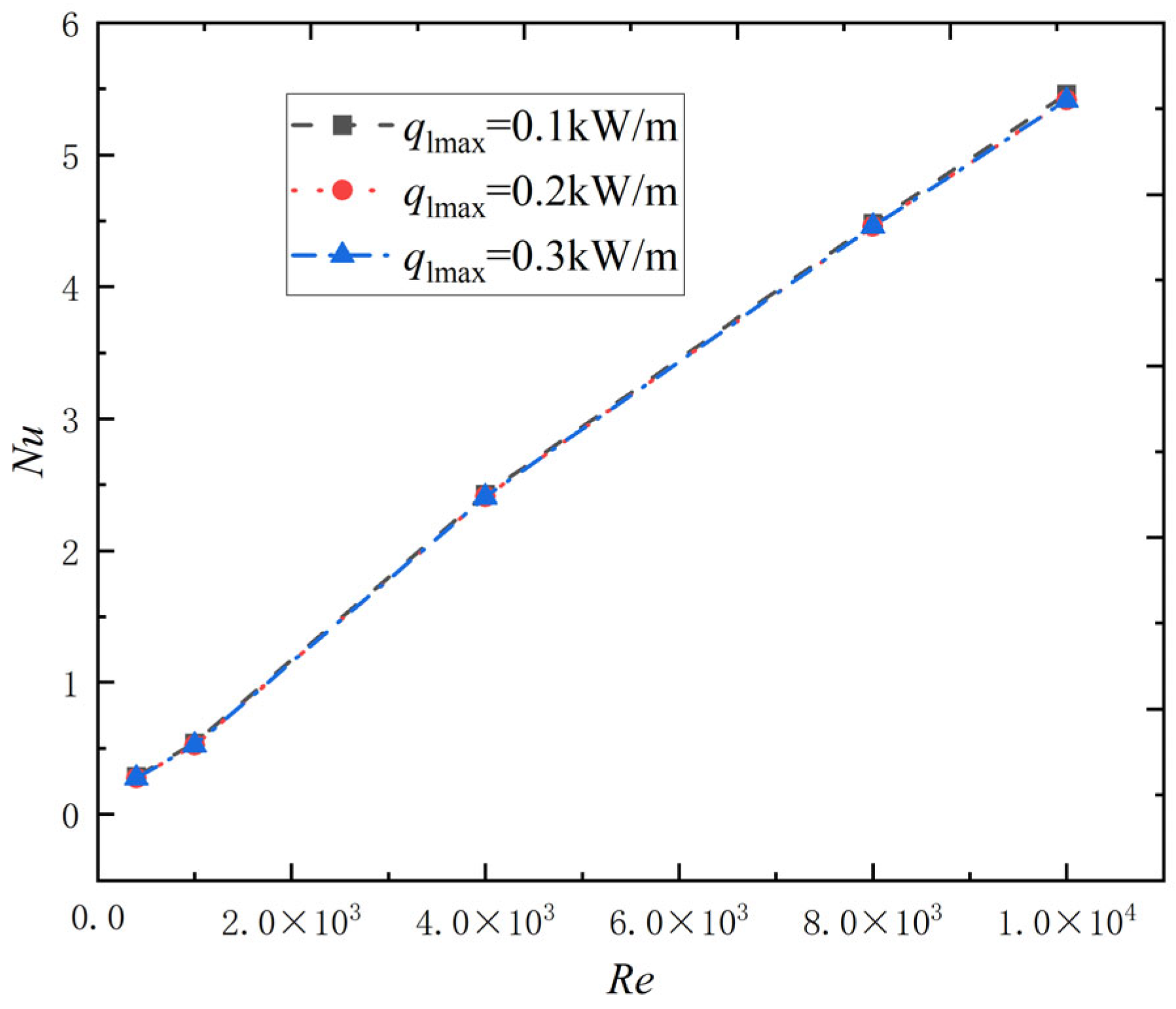
2.2.4. Effect of Reynolds Number and Heating Power Density
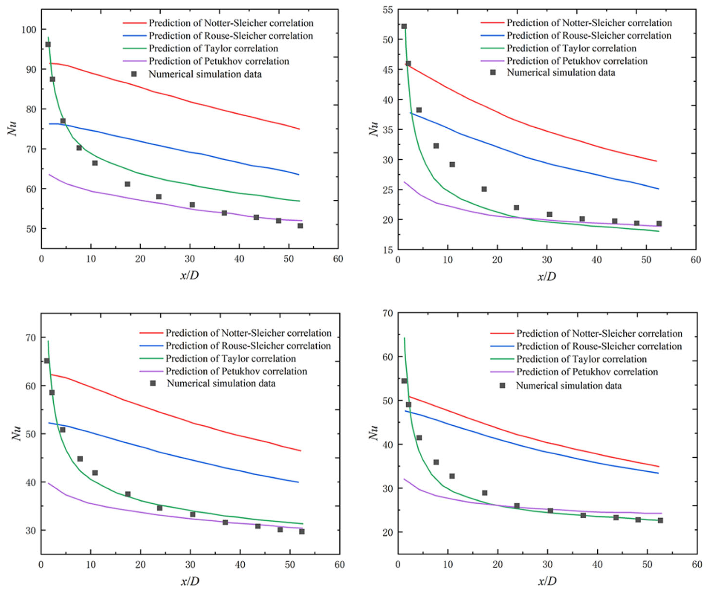
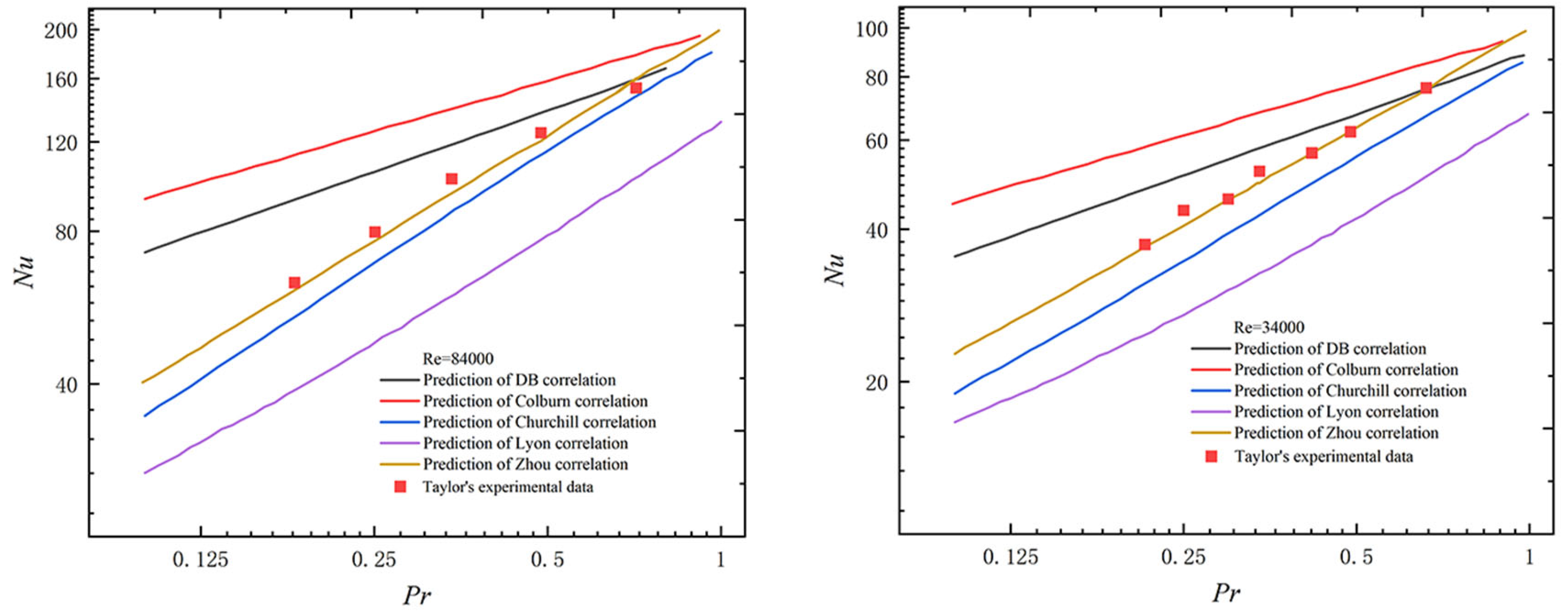
2.3. Applicability Verification of Existing Nusselt Number Correlations
3. Enhanced Heat Transfer Technologies
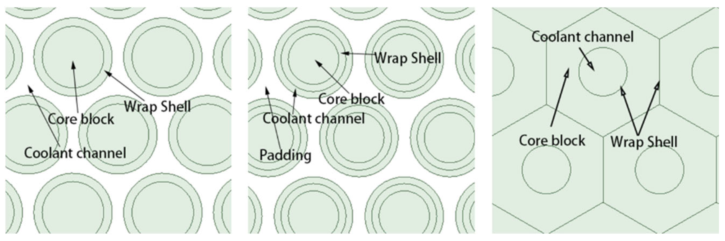
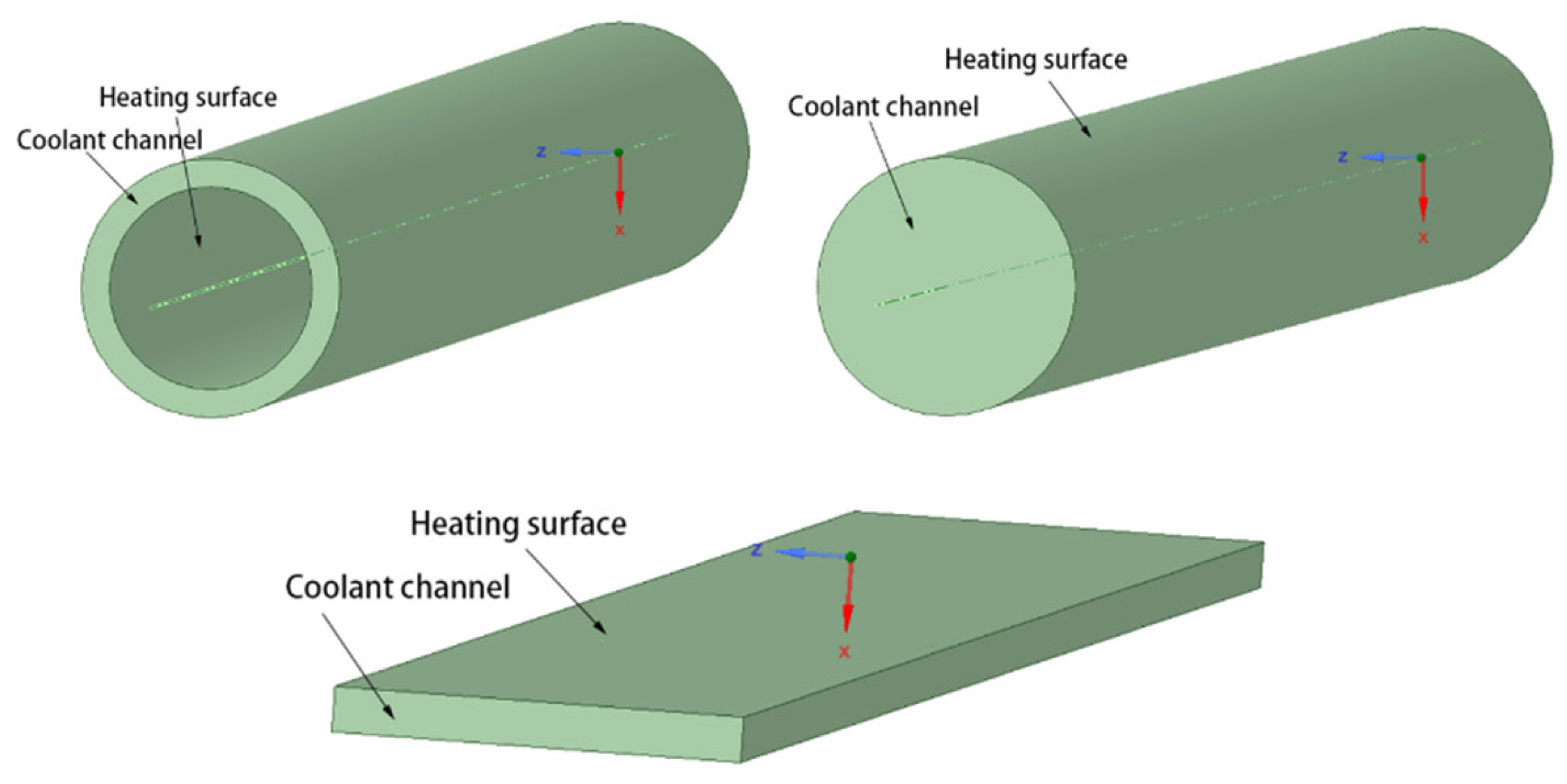
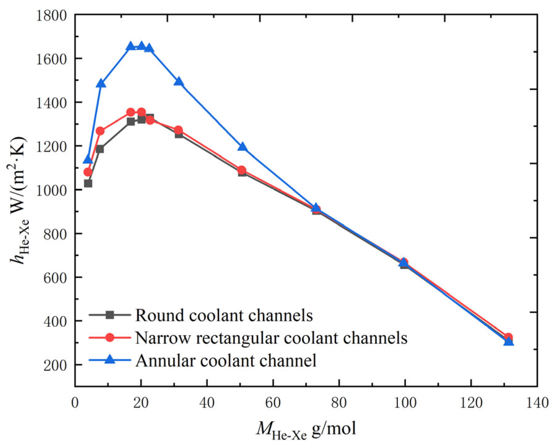
3.1. Effect of Different Pipe Shapes
3.2. Enhanced Heat Transfer in Single Tube Channel
3.3. Enhanced Heat Transfer in Compact Heat Exchanger
4. Summary
- (1)
- More experimental studies on the heat transfer characteristics of the helium–xenon gas mixture should be carried out. The current research on helium–xenon gas mixtures is mainly based on numerical simulations, and the experimental research is essentially confined to Taylor’s experiment. The model verification data of numerical simulations made by later generations also mainly comes from Taylor’s experiment, so the universality of the research results still needs improvement. At the same time, heat transfer experiments of different structural forms and operating conditions should be carried out to provide more support for designing helium–xenon heat exchangers. In addition, the existing feasible correlation should be further verified and optimized to facilitate the heat transfer calculation of helium–xenon mixture in the future.
- (2)
- Enhanced heat transfer technologies for helium–xenon gas mixtures should be urgently studied. Compact and efficient helium–xenon heat exchangers are urgently needed to meet the demand for high energy density and miniaturization of space nuclear power sources. This requires detailed analysis of the heat transfer performance of helium–xenon flow, identifying the key factors affecting the heat transfer thermal resistance, corresponding heat transfer enhancement measures to form an optimized design method applicable to helium–xenon heat exchangers, following which an enhanced heat transfer theory of helium–xenon heat exchangers can be developed. In this process, the commonly used enhanced heat transfer structures can provide reference values, such as threaded tubes, finned tubes, and commonly used compact heat exchangers, such as PCHE, plate fin heat exchangers, etc. We can regard these as the beginning of the research on the enhancement of heat transfer of the helium–xenon mixture. It is necessary to carry out a lot of research and obtain a lot of data as soon as possible, and then make further research plans based on the conclusions obtained.
Funding
Conflicts of Interest
References
- Wang, Z. Research on Brayton Cycle Properties of Helium-Xenon Mixed Working Fluid Based on Space Nuclear Power System. Master’s Thesis, Harbin Institute of Technology, Harbin, China, 2021. [Google Scholar]
- El-Genk, M.S.; Parlos, A.G.; McGhee, J.M.; Lapin, S.; Buden, D.; Mims, J. System design optimization for multimegawatt space nuclear power applications. J. Propuls. Power 1990, 6, 194–202. [Google Scholar] [CrossRef]
- El-Genk, M.S. Space nuclear reactor power system concepts with static and dynamic energy conversion. Energy Convers. Manag. 2008, 49, 402–411. [Google Scholar] [CrossRef]
- El-Genk, M.S. Deployment history and design considerations for space reactor power systems. Acta Astronaut. 2009, 64, 833–849. [Google Scholar] [CrossRef]
- Bennett, G.; Hemler, R.; Schock, A. Space nuclear power: An overview. J. Propuls. Power 1996, 12, 901–910. [Google Scholar] [CrossRef]
- Ren, Y. The good space electric power—Space nuclear power reactor. Nucl. Power Eng. 1993, 14, 269–273. [Google Scholar]
- Yang, Q.; Lu, H. Research and application of space nuclear reactor power. Spacecr. Eng. 1995, 4, 11–20. [Google Scholar]
- Yang, X.; Shi, L. Analysis of Helium-Xenon Mixture Property Influence on Brayton Cycle. At. Energy Sci. Technol. 2018, 52, 1407–1414. [Google Scholar]
- Yu, L. Effect of Proportion of Helium-Xenon Mixtures on the Flow and Heat Transfer Tharacteristics in the Coolant Channel of the Reactor. Master’s Thesis, Harbin Engineering University, Harbin, China, 2020. [Google Scholar]
- Long, Y. Aerodynamic Design and Performance Research on the High-Loaded Helium Compressor. Master’s Thesis, Harbin Engineering University, Harbin, China, 2012. [Google Scholar]
- Dostal, V.; Driscoll, M.J.; Hejzlar, P. A Supercritical Carbon Dioxide Cycle for Next Generation Nuclear Reactors. Mass. Inst. Technol. 2004, 154, 265–282. [Google Scholar]
- Bejan, A.; Lorente, S.; Yilbas, B.; Sahin, A. The effect of size on efficiency: Power plants and vascular designs. Int. J. Heat Mass Transf. 2011, 54, 1475–1481. [Google Scholar] [CrossRef]
- Gnielinski, V. Neue Gleichungen für den Wärme- und den Stoffübergang in turbulent durchströmten Rohren und Kanälen. Forsch. Im Ing. A 1975, 41, 8–16. [Google Scholar] [CrossRef]
- Zhou, B.; Sun, Q.; Sun, J.; Sun, Y. Development and Verification of Calculation Module for He-Xe Flow and Heat Transfer Based on RELAP5. At. Energy Sci. Technol. 2021, 55, 1959–1966. [Google Scholar]
- El-Genk, M.S.; Tournier, J.-M. Noble-Gas Binary Mixtures for Closed-Brayton-Cycle Space Reactor Power Systems. J. Propuls. Power 2007, 23, 863–873. [Google Scholar] [CrossRef]
- Tournier, J.-M.; El-Genk, M.; Gallo, B. Best estimates of binary gas mixtures properties for closed Brayton cycle space applications. In Proceedings of the 4th International Energy Conversion Engineering Conference and Exhibit (IECEC), San Diego, CA, USA, 26–29 June 2006; p. 4154. [Google Scholar]
- Li, Z.; Yang, X.; Wang, J.; Zhang, Z. Thermodynamic analysis of a Brayton cycle system for a space power reactor. J. Tsinghua Univ. (Sci. Technol.) 2017, 57, 537–543+549. [Google Scholar]
- Taylor, M.; Bauer, K.; McEligot, D. Internal forced convection to low-Prandtl-number gas mixtures. Int. J. Heat Mass Transf. 1988, 31, 13–25. [Google Scholar] [CrossRef]
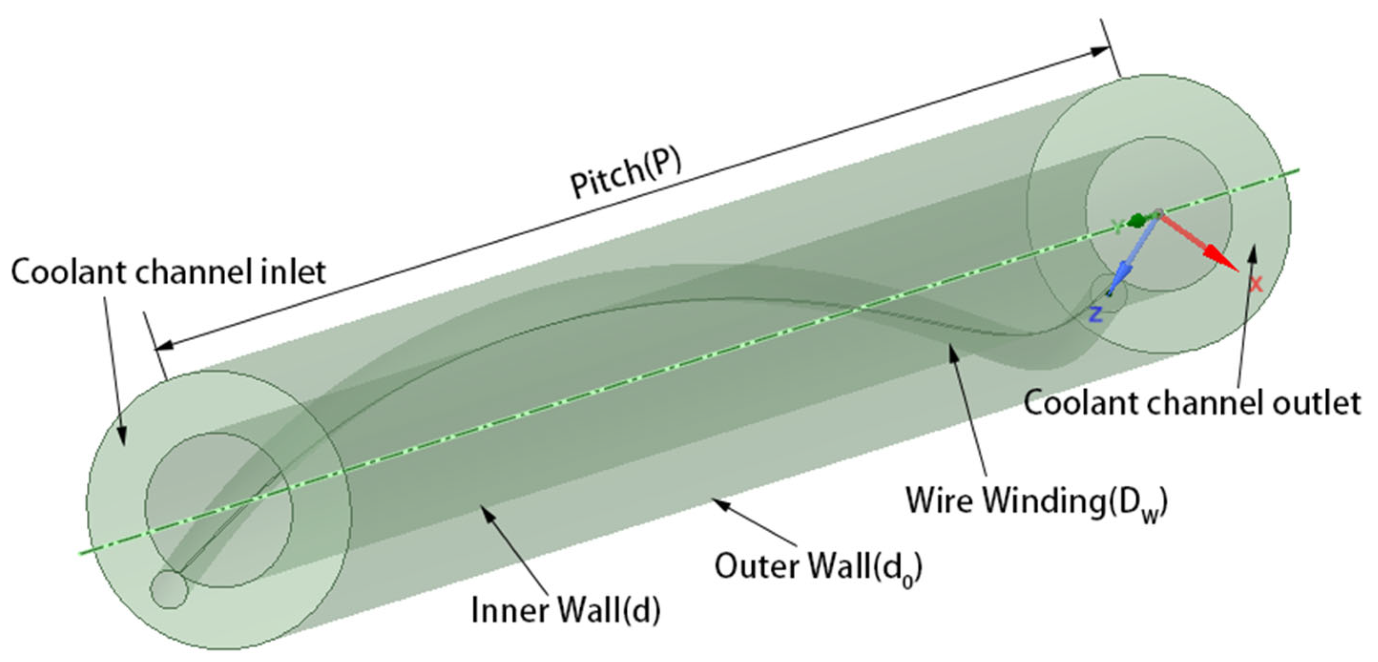
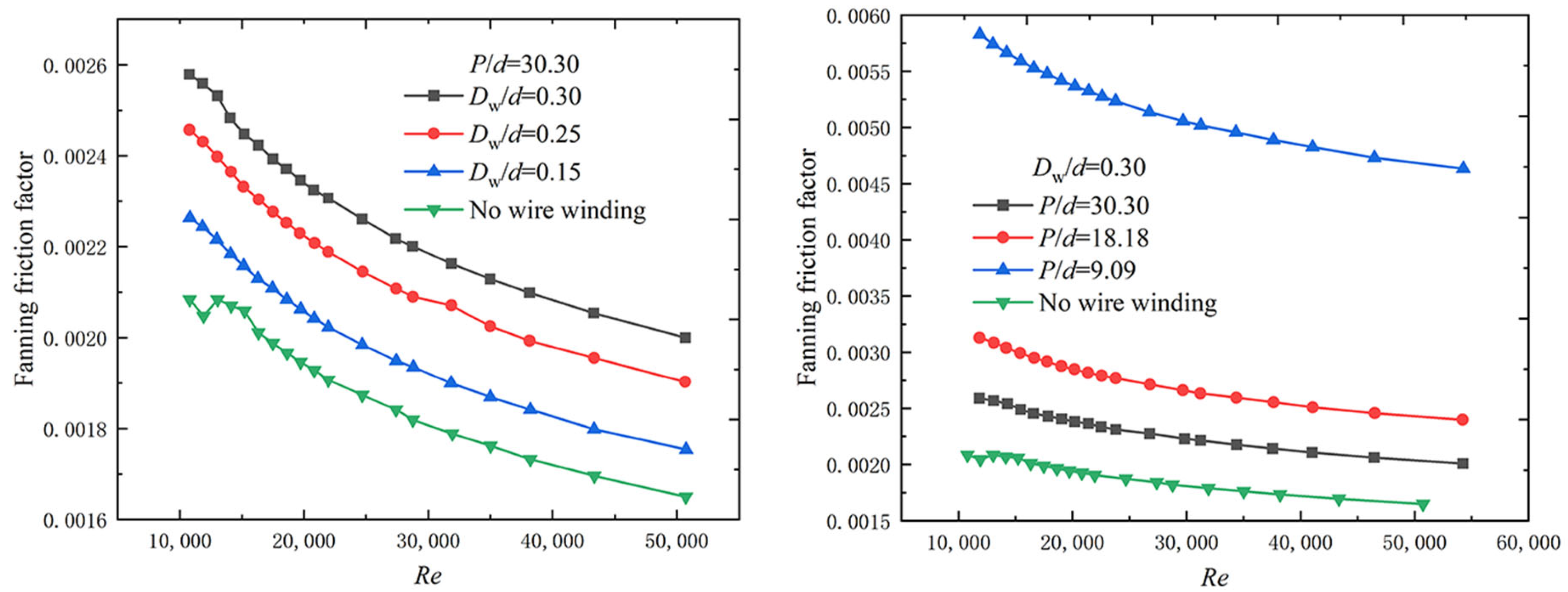
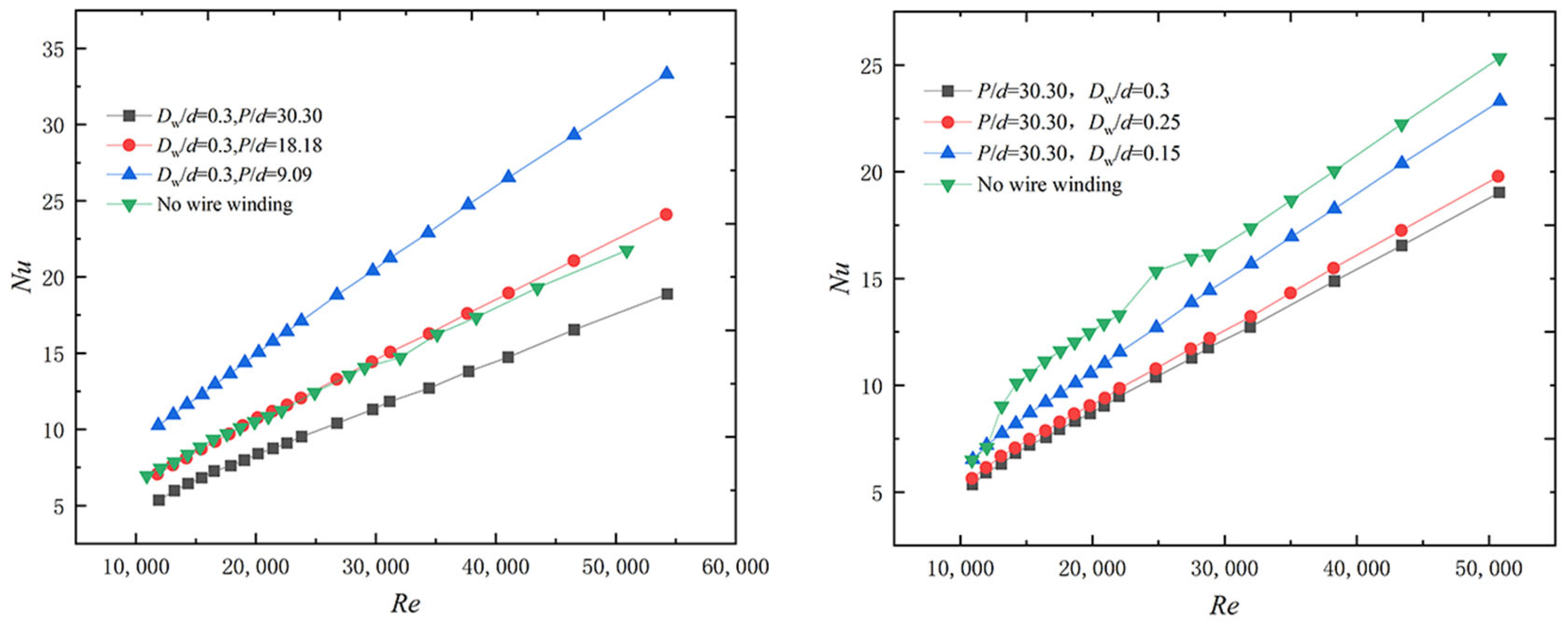
- Chen, S.; Qin, H.; Wang, C.; Zhang, Y.; Zhang, D.; Qiu, S.; Tian, W.; Su, G. Flow and Heat Transfer Characteristic of He-Xe Gas Mixture with Helical Wire Structure. At. Energy Sci. Technol. 2021, 55, 991–999. [Google Scholar]
- Sun, Q.; Zhang, H. Numerical study on heat transfer performance of cooling channels in space core. Appl. Therm. Eng. 2022, 210, 118274. [Google Scholar] [CrossRef]
- Zhou, B.; Ji, Y.; Sun, J.; Sun, Y.-L. Nusselt number correlation for turbulent heat transfer of helium–xenon gas mixtures. Nucl. Sci. Tech. 2021, 32, 128. [Google Scholar] [CrossRef]
- Petukhov, B.S. Heat Transfer and Friction in Turbulent Pipe Flow with Variable Physical Properties. Adv. Heat Transf. 1970, 6, 503–564. [Google Scholar]
- Sleicher, C.; Rouse, M. A convenient correlation for heat transfer to constant and variable property fluids in turbulent pipe flow. Int. J. Heat Mass Transf. 1975, 18, 677–683. [Google Scholar] [CrossRef]
- Notter, R.; Sleicher, C. A solution to the turbulent Graetz problem—III Fully developed and entry region heat transfer rates. Chem. Eng. Sci. 1972, 27, 2073–2093. [Google Scholar] [CrossRef]
- Dittus, F.; Boelter, L. Heat transfer in automobile radiators of the tubular type. Int. Commun. Heat Mass Transf. 1985, 12, 3–22. [Google Scholar] [CrossRef]
- Colburn, A.P. A method of correlating forced convection heat-transfer data and a comparison with fluid friction. Int. J. Heat Mass Transf. 1964, 7, 1359–1384. [Google Scholar] [CrossRef]
- Churchill, S.W. Comprehensive Correlating Equations for Heat, Mass and Momentum Transfer in Fully Developed Flow in Smooth Tubes. Ind. Eng. Chem. Fundam. 1977, 16, 109–116. [Google Scholar] [CrossRef]
- Lyon, R.N. Liquid metal heat-transfer coefficients. Chem. Eng. Prog. 1951, 47, 75–79. [Google Scholar]
- Huang, D.; Li, Z.; Yu, L.; He, X.; Zhao, F.; Tan, S. Influence of helium-xenon mixing ratio on flow heat transfer characteristics of reactor channels. J. Harbin Eng. Univ. 2021, 42, 745–750. [Google Scholar]
- Yang, Y.; Huo, H. Analysis of Heat Transfer and Flow Characteristic for High Temperature Helium-xenon Gas Microchannel Regenerator. At. Energy Sci. Technol. 2018, 52, 2156–2163. [Google Scholar]
- Huang, Y.; Xiao, X.; Kang, H.; Lv, J.; Zeng, R.; Shen, J. Thermal management of polymer electrolyte membrane fuel cells: A critical review of heat transfer mechanisms, cooling approaches, and advanced cooling techniques analysis. Energy Convers. Manag. 2022, 254, 115–221. [Google Scholar] [CrossRef]
- Chen, H.; Ruan, X.-H.; Peng, Y.-H.; Wang, Y.-L.; Yu, C.-K. Application status and prospect of spray cooling in electronics and energy conversion industries. Sustain. Energy Technol. Assess. 2022, 52, 102–181. [Google Scholar] [CrossRef]
- Bhandari, P.; Prajapati, Y. Influences of tip clearance on flow and heat transfer characteristics of open type micro pin fin heat sink. Int. J. Therm. Sci. 2022, 179, 107–714. [Google Scholar]


| Parameter | Formula |
|---|---|
| Specific heat capacity | |
| Density | |
| Dynamic Viscosity | |
| Thermal conductivity |
| Parameter | Value |
|---|---|
| d/mm | 0.00587 |
| δ/mm | 0.00056 |
| L1/mm | 328.72 |
| L2/mm | 352.2 |
| Parameter | Value/Formula |
|---|---|
| L/m | 0.985 |
| /mm−1 | 0.08932 |
| /kW/m |
| Parameter | Value |
|---|---|
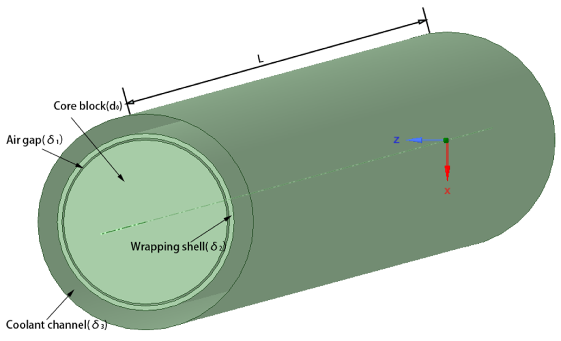
| d1/m | 0.01819 |
| 0.00022 | |
| 0.00051 | |
| 0.00216 | |
| L/m | 0.608 |
| P/W | 3480 |
| Re | ql,max kW/m | G kg/s | v m/s | Tin K | pout MPa |
|---|---|---|---|---|---|
| 400 | 0.1/0.2/0.3 | 9.9605 × 10⁻⁵ | 1.5787 | 1136.4 | 2.8 |
| 1000 | 0.1/0.2/0.3 | 2.4901 × 10⁻⁴ | 3.9467 | 1136.4 | 2.8 |
| 4000 | 0.1/0.2/0.3 | 9.9605 × 10⁻⁴ | 15.7868 | 1136.4 | 2.8 |
| 8000 | 0.1/0.2/0.3 | 1.9921 × 10⁻³ | 31.5737 | 1136.4 | 2.8 |
| 10,000 | 0.1/0.2/0.3 | 2.4901 × 10⁻³ | 39.4675 | 1136.4 | 2.8 |
| Serial Number | Name | Formula | Range of Application |
|---|---|---|---|
| 1 | Petukhov [22] | 104 ≤ Re ≤ 5 × 10⁶ | |
| 2 | Sleicher and Rouse [23] | 104 ≤ Re ≤ 5 × 10⁶ | |
| 3 | Notter and Sleicher [24] | 104 ≤ Re ≤ 5 × 10⁶ 1 < Tw/Tb < 5 | |
| 4 | Taylor [18] | 1.8 × 10⁴ ≤ Re ≤6 × 10⁴ Tw/Tb < 2 | |
| 5 | Dittus and Bolter [25] | 0.7 ≤ Pr ≤ 120 104 ≤ Re ≤ 1.2 × 10⁵ | |
| 6 | Colburn [26] | 0.5 ≤ Pr ≤ 100 | |
| 7 | Churchill [27] | 0.001 ≤ Pr ≤ 200 | |
| 8 | Lyon [28] | Pr < 0.1 | |
| 9 | Zhou [21] | 1.8 × 10⁴ ≤ Re ≤6 × 10⁴ 0.21 ≤ Pr ≤ 0.30 Tw/Tb < 2 |
| Parameter | Condition 1 | Condition 2 | Condition 3 | Condition 4 |
|---|---|---|---|---|
| MHe-Xe/g/mol | 83.8 | 39.5 | 28.3 | 14.5 |
| Pr | 0.25 | 0.21 | 0.23 | 0.30 |
| Re | 63,987~85,802 | 19,174~36,183 | 34,443~53,390 | 19,485~34,042 |
| q/W/m2 | 43,637 | 136,770 | 157,094 | 296,622 |
| G/kg/(m2·s) | 350.6 | 156.4 | 229.1 | 139.7 |
| Pout/Pa | 471,502 | 563,474 | 928,019 | 806,581 |
| Parameter | Value |
|---|---|
| dout/mm | 19.65 |
| δ/mm | 2.16 |
| L/mm | 1118 |
| Tin/K | 882 |
| Tout/K | 1125 |
| vin/m/s | 20 |
| Pin/MPa | 2 |
| Pout/MPa | 1.991 |
| Types of Coolant Channels | S/10−4 m2 | de/mm |
|---|---|---|
| Annular coolant channel | 1.48 | 4.32 |
| Circular coolant channels | 1.48 | 13.39 |
| Narrow rectangular coolant channels | 1.48 | 7.22 |
| Parameter | Value |
|---|---|
| Tout/K | <1200 |
| Tw/K | <1800 |
| q/kW/m2 | 60 |
| vin/m/s | 10~27 |
| p/MPa | 1.5~2.5 |
| Conditions | P/d | Dw/d | d0/d |
|---|---|---|---|
| Condition 1 | 30.30 | 0.3 | 1.8 |
| Condition 2 | 18.18 | 0.3 | 1.8 |
| Condition 3 | 9.09 | 0.3 | 1.8 |
| Condition 4 | 30.30 | 0.25 | 1.8 |
| Condition 5 | 30.30 | 0.15 | 1.8 |
| Parameter | Value |
|---|---|
| G/g/s | 0.2125 |
| Thot,in/K | 961 |
| Tcold,in/K | 516 |
| Phot,in/MPa | 1.15 |
| Pcold,in/MPa | 2.1 |
| L/mm | 390 |
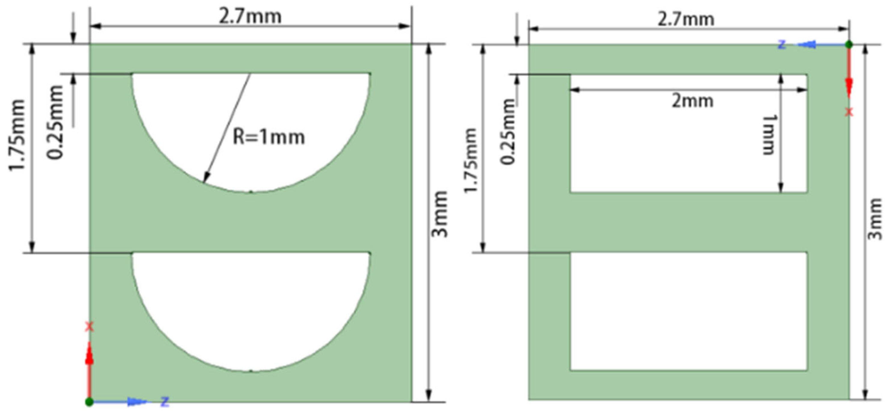
| Parameter | Fine Engraving Process | Etching Process |
|---|---|---|
| Thot,out/K | 572.2 | 571.6 |
| Tcold,out/K | 905 | 905.8 |
| vhot,in/m/s | 18.3 | 23.2 |
| vcold,in/m/s | 11.0 | 14.1 |
| ΔPhot/Pa | 7508 | 12,574.8 |
| ΔPcold/Pa | 4491 | 7472 |
Disclaimer/Publisher’s Note: The statements, opinions and data contained in all publications are solely those of the individual author(s) and contributor(s) and not of MDPI and/or the editor(s). MDPI and/or the editor(s) disclaim responsibility for any injury to people or property resulting from any ideas, methods, instructions or products referred to in the content. |
© 2022 by the authors. Licensee MDPI, Basel, Switzerland. This article is an open access article distributed under the terms and conditions of the Creative Commons Attribution (CC BY) license (https://creativecommons.org/licenses/by/4.0/).
Share and Cite
Zhao, F.; Mei, Y.; Liang, T.; Wang, B.; Jing, H.; Chen, W. A Review on Heat Transfer Characteristics and Enhanced Heat Transfer Technology for Helium–Xenon Gas Mixtures. Energies 2023, 16, 68. https://doi.org/10.3390/en16010068
Zhao F, Mei Y, Liang T, Wang B, Jing H, Chen W. A Review on Heat Transfer Characteristics and Enhanced Heat Transfer Technology for Helium–Xenon Gas Mixtures. Energies. 2023; 16(1):68. https://doi.org/10.3390/en16010068
Chicago/Turabian StyleZhao, Fulong, Yiguo Mei, Tiebo Liang, Bin Wang, Hao Jing, and Weixiong Chen. 2023. "A Review on Heat Transfer Characteristics and Enhanced Heat Transfer Technology for Helium–Xenon Gas Mixtures" Energies 16, no. 1: 68. https://doi.org/10.3390/en16010068