Article

Research on Hydrogen Production by Water Electrolysis Using a Rotating Magnetic Field

1
School of Mechanical Engineering, Kunsan National University, Gunsan-si 54150, Jeollabuk-do, Republic of Korea
2
School of Engineering, Jilin Business and Technology College, Changchun 130507, China
*
Author to whom correspondence should be addressed.
Energies 2023, 16(1), 86; https://doi.org/10.3390/en16010086
Submission received: 14 November 2022 / Revised: 15 December 2022 / Accepted: 19 December 2022 / Published: 21 December 2022

Abstract

:
In this paper, the effect of rotating magnetic fields on hydrogen generation from water electrolysis is analyzed, aiming to provide a research reference for hydrogen production and improving hydrogen production efficiency. The electrolytic environment is formed by alkaline solutions and special electrolytic cells. The two electrolytic cells are connected to each other in the form of several pipes. The ring magnets are used to surround the pipes and rotate the magnets so that the pipes move relative to the magnets within the ring magnetic field area. Experimentally, the electrolysis reaction of an alkaline solution was studied by using a rotating magnetic field, and the effect of magnetic field rotation speed on the electrolysis reaction was analyzed using detected voltage data. The experimental phenomenon showed that the faster the rotation speed of the rotating magnetic field, the faster the production speed of hydrogen gas.

1. Introduction

With the development of society and the progress of technology, people’s demand for energy is increasing. Traditional energy resources are no longer enough to support the development of modern people, so people have started to develop renewable energy manufacturing technologies. Among them, hydrogen energy is the main object of current research in renewable energy and is a common focus of scientists from various countries [1]. There are many ways to produce hydrogen, among which water electrolysis to produce hydrogen is the most widely used. In order to improve the efficiency of water electrolysis reactions, researchers have come up with a variety of solutions. Electrolytic water technology is currently available in three main electrolytic cell technologies: alkaline water electrolysis (AWE), proton exchange membrane electrolysis (PEM), and solid oxide electrolysis (SOEC) [2]. Both AWE and PEM are technologies that have been studied more deeply under low temperature conditions; however, SOEC technology is still in the development stage [3]. Compared with the other two technologies, AWE has the advantages of lower cost and longer lifetime [4,5,6,7]. Thus, AWE is the most widely applied technology today.
Dohyung Jang et al. [8] pointed out that the effect of electrode overvoltage could be controlled by controlling the pressure of alkaline water electrolysis to enhance the efficiency of alkaline water electrolysis.
Frank Allebrod et al. [9] analyzed the effect of temperature on the rate of hydrogen production when performing water electrolysis. As the temperature increases, the impedance decreases and the current density increases. This results in an increase in the rate of hydrogen production.
N. A. Burton et al. [10] proposed a method to improve the efficiency of solar water electrolysis for hydrogen production. Further research on enhanced solar-hydrogen hybrid coupling technology, the application of magnetic fields, the application of light energy, the application of ultrasonic fields, and the application of pulsating electric fields can be used to improve the efficiency of renewable hydrogen production.
Lin et al. [11] used electrodes with different magnetic properties for electrolytic hydrogen production and explored the effect of magnetohydrodynamics on the electrolytic hydrogen production process. The observed experiments revealed that the direction of the magnetic force would determine the direction of the Lorentz force, the convection of the electrolytic solution, the direction of the bubble motion, and thus the efficiency of the electrolysis of water. In addition, ferromagnetic electrodes are more susceptible to magnetic influence and exponentially increase the Lorentz effect. The results show that magnetism does increase the efficiency of water electrolysis and that ferromagnetism is the best choice of electrode.
Mehmet Fatih Kaya et al. [12] investigated the performance of alkaline water electrolysis with different cost-effective electrodes under a magnetic field and concluded that graphite was the most suitable choice for the anode and high-carbon steel (HCS) for the cathode. Moreover, the magnetic field has a positive effect on the anode and cathode, which can improve production efficiency and reduce production costs.
Liu et al. [13] studied water electrolysis experiments using flat plate electrodes in a parallel non-uniform magnetic field, and the voltage data obtained in electrolysis showed that the magnetohydrodynamics (MHD) flow due to the non-uniform Lorentz force positively influenced the overall electrolysis reaction in the presence of a non-uniform magnetic field, with an increase in electrolysis efficiency.
According to the above-mentioned research, magnetohydrodynamics (MHD) can have a positive effect on water electrolysis experiments due to the presence of a magnetic field, but most of the studies by scholars have been conducted with a fixed magnetic field and given a certain electrolytic voltage. Therefore, in this paper, a rotating magnetic field is used to perform experiments on water electrolysis. Firstly, the effect of induced voltage and magnetic field on the charged ions in solution is used to analyze the variation of voltage inside the electrolyzer. Then the rotating magnetic field is applied to promote water electrolysis and find the effect on hydrogen production speed with a constant voltage provided externally.

2. Theories

2.1. Water Electrolysis Theory

Hydrogen production by water electrolysis is the inverse reaction of the oxidation-reduction reaction of hydrogen and oxygen in a fuel cell. Water electrolysis is a reaction in which hydrogen is liberated by a reduction reaction at the cathode and oxygen is liberated by an oxidation reaction at the anode. As shown in Figure 1, the electrode cell for the electrolysis of an alkaline aqueous solution to produce hydrogen consists of a pair of electrodes submerged in the electrolyte and a diaphragm between the electrodes to prevent gas penetration. When the electrodes are applied with a certain voltage of direct current, the water decomposes, producing hydrogen at the cathode and oxygen at the anode, respectively. The conductivity of an aqueous solution is the result of the movement of charged ions in the solution in an electric field, and the magnitude of its conductivity (the reciprocal of its resistivity) is related to the concentration of ions in the aqueous solution. Pure water is a very weak electrolyte, and it has a very poor ability to conduct electricity. Therefore, it is usually necessary to add some strong electrolytes to increase the conductivity of the solution so that water can be electrolyzed smoothly into hydrogen and oxygen. Strongly alkaline solutions such as NaOH or KOH are usually used, and the reactions at the electrodes during the electrolysis of alkaline aqueous solutions are mainly [2]:
Cathode: 4H2O + 4e → 2H2 + 4OH
Anode: 4OH → O2 + 2H2O + 4e
Total reaction formula: 2H2O → 2H2 + O2
Electrolysis of 1 mole of water produces 1 mole of hydrogen and 0.5 mole of oxygen.

2.2. Fleming’s Right-Hand Rule and Faraday’s Law of Electromagnetic Induction

Fleming’s right-hand rule (also known as the generator rule or right-hand rule) is a rule created by Fleming, a British engineer, to find the direction of current generated by a conductor moving under a magnetic field. This is peformed by having three fingers of the right hand perpendicular to each other, with the direction of the thumb being the direction of wire movement, the direction of the index finger pointing in the direction of the magnetic field, and the direction of the middle finger pointing in the direction of the current [14].
Faraday’s law of electromagnetic induction states that when the magnetic flux through a closed conducting loop changes, an induced current is generated in loop [15]. That is, a part of the conductor of a conducting circuit in a constant magnetic field moves relative to the magnetic field, causing the charged particles to move due to the Lorentz force to form an induced current, which in turn generates an induced electric potential.
The relationship between Fleming’s right-hand rule and Faraday’s law of electromagnetic induction is very close. Both are theories used to describe the phenomenon of electromagnetic induction. However, Fleming’s right-hand rule is the theory used to determine the direction of the induced current, while Faraday’s law of electromagnetic induction is the theory used to calculate the value of the induced current or induced electric potential. We usually use both theories for related studies.

3. Experiment

3.1. Experimental Apparatus

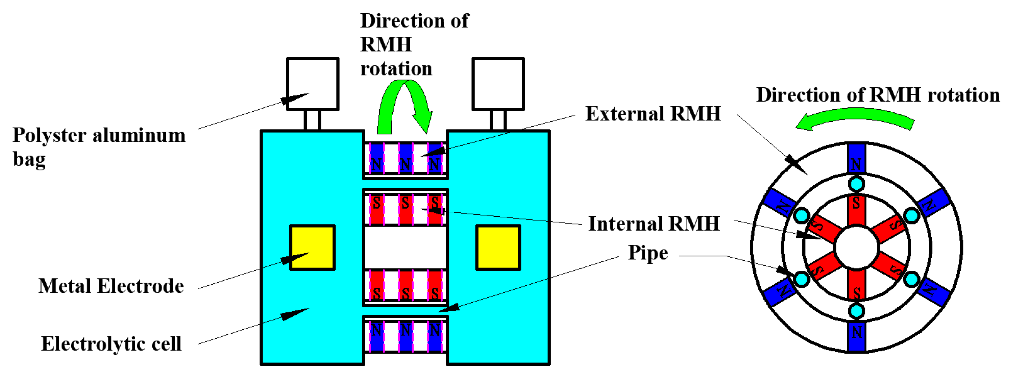
The overall front of the experimental setup is shown in Figure 2. The experimental apparatus consists of electrolytic cells, metal electrodes, a rotary magnet holder (RMH), gas collection devices (polyester aluminum bags), a driving motor, a voltage detection apparatus, and a frame. A high-speed camera is placed on the side of the cathode electrolyzer to take pictures of the hydrogen production.
The shape of the electrolytic cell is rectangular with trapezoidal top and bottom ends, and the material is Plexiglas. The two electrolytic cells are flanged separately to hold the electrodes. The flanges are set with metal rods in the middle. The long side of the metal rod is placed and fixed with positive and negative metal electrodes, and the short side is used with wires to connect the voltage detection instrument (cDAQ-9178 and NI 9206, National Instruments Corp., Austin, TX, USA). The metal electrodes were made of copper sheets as positive and negative electrodes. A number of pipes were used to interconnect the two electrolytic cells. The RMH was divided into an internal RMH and an external RMH. A motor (9SRDK2-90F2-C 83, DKM Motor Co., Ltd., Incheon, Republic of Korea) was connected with a belt drive to drive the RHM in a rotary motion around the six pipes. A gas collection device was connected with a hose above the electrolysis tank, and a hose and valve were used below to control the injection and discharge of the electrolysis solution. The electrolysis solution is a 20% NaOH solution.
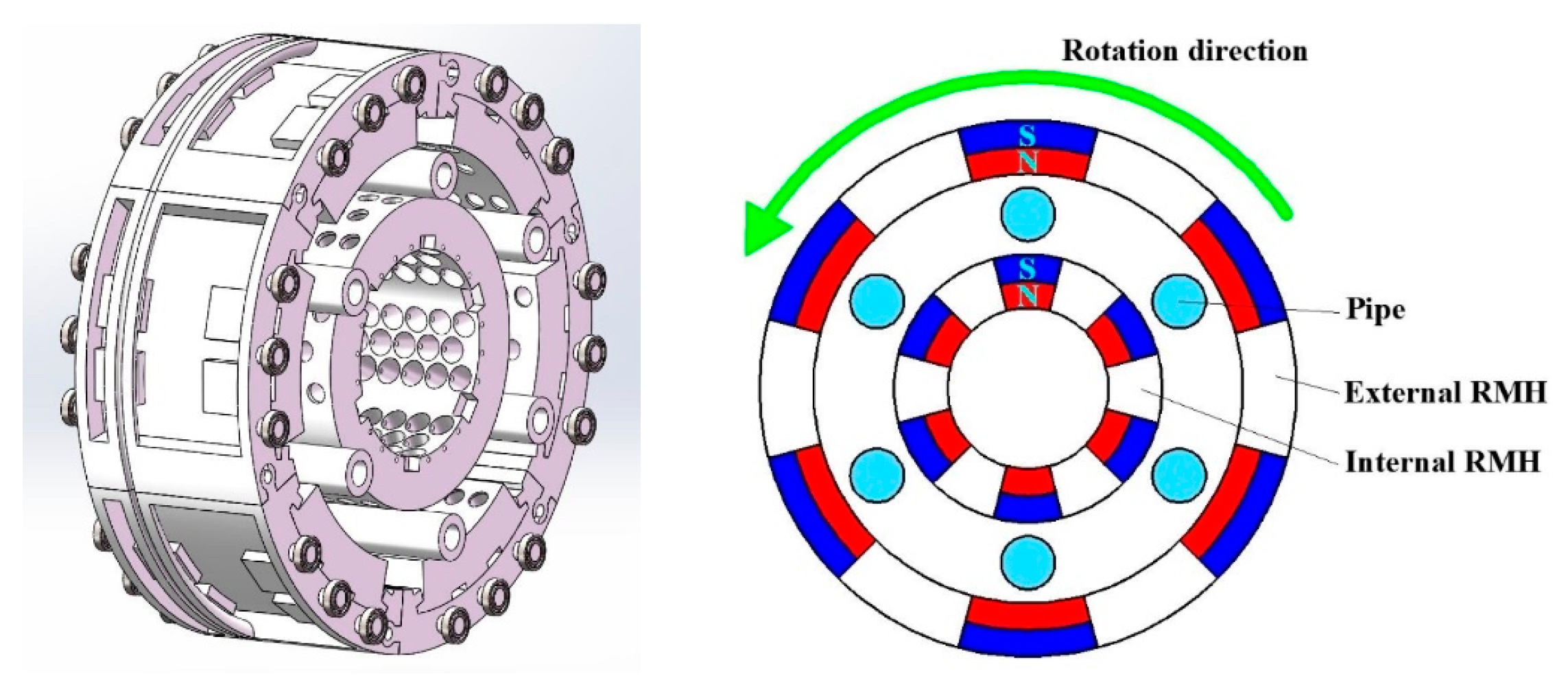
As shown in Figure 3, RMH is divided into two parts: internal RMH and external RMH. Neodymium magnets with a diameter of 10 mm and a length of 15 mm are embedded in the RMH. The average magnetic field strength of the magnets was measured at 4510 Gauss (approximately equal to 0.45 T), and a total of 240 magnets were used (120 each for the inner and outer RMH). As shown in Figure 4 set up according to the interval of 15°-15°-30°, the number of magnets in each row is different and set up according to the way of 7-6-7 number of magnets. The spacing of the magnets is set to produce a fluctuating type of voltage. Due to the size limitation, type 6 magnets are set in the middle of two rows of type 7 magnets, exactly staggered to avoid interference. It is also possible to verify the effect of the length of the magnetic field region on the voltage.

3.2. Experimental Methods

First, the metal electrodes were placed into the electrolytic cells, fixed with a flange, and connected to a voltage detection device to detect the voltage of the electrodes in the electrolytic cells in real time at a data detection frequency of 3000 Hz. Then, the electrolyzer was filled with a 20% NaOH solution until it was full. The first program was to turn on the motor to drive the rotating magnet holder (RMH) without applying voltage, keep the rotational speed constant, and after a period of time when the rotational speed was stable, the change in voltage was detected. Then, different rotational speeds were used to observe the change in electrolysis reaction, which were 0 rpm, 100 rpm, 200 rpm, 300 rpm, and 400 rpm (unit: revolutions per minute). The voltage generated by the magnetic field was detected at each of the five rotational speeds. The second program then applied an external constant voltage of 10 V and used the camera to photograph the hydrogen production at five different rotational speeds.

4. Results and Discussion

4.1. Results

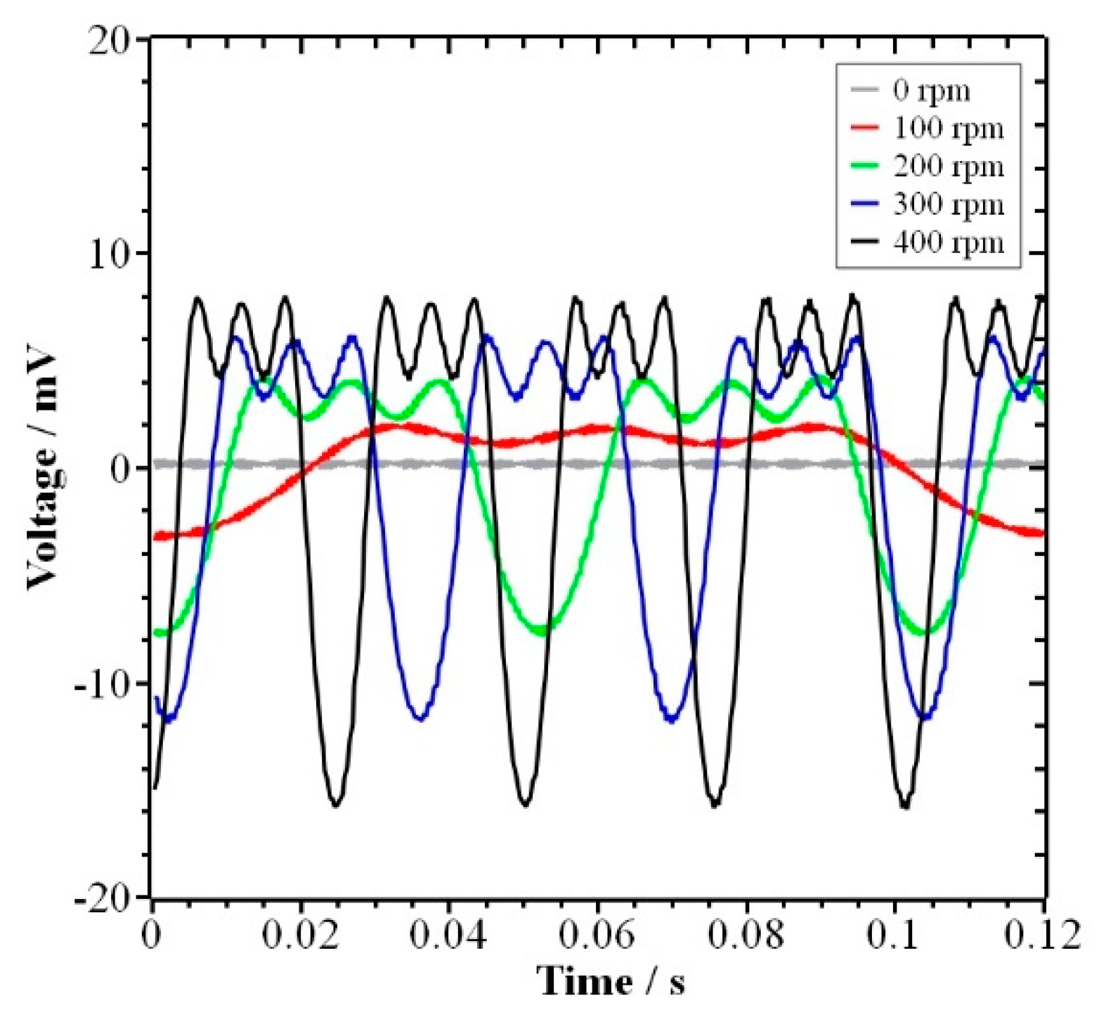
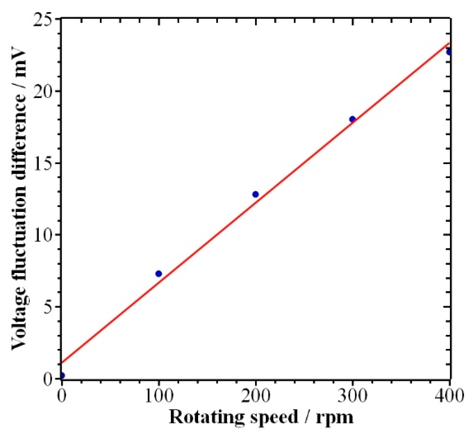
By examining the voltage without external voltage, one was able to obtain the data shown in Figure 5. When the rotating magnet frame was rotating at a certain speed, the voltage fluctuated regularly, as shown in Figure 6. The speed was 0 rpm, 100 rpm, 200 rpm, 300 rpm, and 400 rpm, respectively. As shown in Figure 6, the difference between the maximum and minimum voltage values, i.e., the amplitude of the voltage, became larger and the fluctuation period became shorter as the rotational speed increased. To verify the effect of the speed of RMH on the rate of hydrogen production, a constant voltage of 10 V was added to the experimental setup, and hydrogen production was observed, as shown in Figure 7. Images were recorded using the Samsung camera SM-G977N at various speeds with an exposure time of 1/250 s, ISO speed of 400, aperture value of f/1.5, and maximum aperture of 1.16. Under the action of the rotating magnetic field, hydrogen bubbles were generated on the surface of the negative electrode. The speed and number of bubbles generated vary at different rotational speeds, and the number of bubbles increases with the increase in rotational speed.

4.2. Discussion

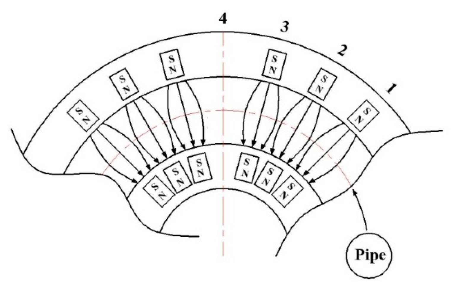
Using a pipe filled with NaOH solution as a conductor, the motion of a conducting fluid in an applied magnetic field is governed by the law of magnetohydrodynamics (MHD) [16]. When the conductor passes through the magnetic field at a certain speed, the direction of motion of the conductor is such that it cuts the magnetic induction lines, and then an induced current is generated inside the conductor [17]. The RMH is manufactured in the shape of a circle, and the RMH is set into two parts, internal RMH and external RMH, in order to ensure that the pipes keep the relative distance between them constant and the direction of cutting magnetic induction lines constant. When the RMH is rotated, the pipes are continuously moving relative to the RMH and forcing the ions to migrate, thus generating an induced current. According to magnetohydrodynamics, the cations and anions in the solution migrate rapidly to the metal electrodes on both sides under the action of the RMH. The cations move to the cathode, forcing the water molecules to absorb electrons from the cathode and electrolyze them into H2 and OH. The generated OH is transported to the anode due to the magnetic field to produce O2 and H2O, and the electrons are absorbed by the anode and transferred to the cathode by an external circuit. This completes the process of electrolyzing water using DC current to produce hydrogen gas. In this experiment, the six pipes between the two electrolytic cells are equivalent to conductors, and the RMH surrounds the pipes in a rotary motion, which can be regarded as the motion of the RMH not moving while the pipes are cutting magnetic induction lines, as shown in Figure 8.
Under DC electrolysis conditions, the efficiency of alkaline water electrolysis depends to a large extent on the current fluctuations [18]. Based on the fluctuating state of the detection voltage, it can be considered that the induced current (migration of ions) is influenced by changes in the magnetic field. The detection voltage is strongest when the pipe moves to 1, 2, and 3. When the pipe moves between 1 and 2 and between 2 and 3, the magnetic field strength decreases slightly, causing the voltage to decrease only slightly because the magnets are very close together. When the pipe moves to 4, the magnetic field strength is the weakest (i.e., the magnetic flux is the least), so the voltage is the smallest. According to Faraday’s law [19], the voltage obtained from the detection can be considered the induced voltage, then the detected voltage of this experiment also conforms to the formula for the induced voltage, so
e = v B l sin θ
e is the induced voltage, v is the velocity of motion, B is the magnetic flux density, l is the length of the pipe, and θ is the angle between the direction of motion of the wire and the direction of the magnetic field [20]. Because the direction of motion of the pipe is the tangential direction of RMH rotary motion and the magnetic field direction is pointing to the center of the circle, the angle between the direction of motion and the magnetic field direction is 90°, that is, sin θ = 1. Therefore,
e = v B l
Since the values of magnetic flux density B and pipe length l are constant, the magnitude of the value of induced voltage e depends on the velocity v. At this point, since the rotational speed is known, the velocity v can be calculated from the rotational speed n,
v = 2 π × R × n
where n is the rotational speed and R is the radius of the circle in which the pipe is located.
It is known from the formula that the magnetic field strength and the speed of motion are the influencing factors of the induced electric potential. When the speed is constant, the induced voltage will become smaller as the magnetic field strength becomes smaller; that is, the fluctuation of the voltage at a certain speed in this experiment is shown in the pipes in Figure 8 at 4 where the voltage shows the minimum value. When the magnetic field strength is constant, the faster the speed, the greater the induced voltage. That is, the strength of the magnetic field at the same location is the same, and when the speed of the pipes through the magnetic field is greater, the induced voltage is greater. Since the arrangement of magnets in RMH is in the form of 7-6-7, the fluctuating shape shown in Figure 5 occurs in the detection of voltage, which is considered a phenomenon. This phenomenon is caused by the movement of ions in a periodic permanent magnet (PPM) magnetic field.
The PPM periodically exerts a strong convergence force on the ions, which not only counteracts the divergence force of the space ions but furthermore gives the ions an on-axis acceleration, causing them to change from off-axis to on-axis motion [21]. After exiting this region, the convergence force of the magnetic field is not sufficient to counteract the divergence force of the space ions [22]. The ions achieves an off-axis radial acceleration, which gradually decreases the on-axis velocity of the ions from the strong magnetic field region and finally becomes off-axis motion until they enter the strong magnetic field region in the next cycle [23]. It is clear that during this process, the ions are moving on-axis and off-axis at times, i.e., there is pulsation [24]. Therefore, as can be seen in Figure 5, the experimentally obtained voltage data also show a pulsating waveform. The peaks in the waveform are formed when the pipes pass through the magnetic field region, where the highest peaks on both sides are caused by the 7-6-7 in a 7-type arrangement of the magnetic field region. The middle crest is caused by the magnetic field area of type 6 arrangement in 7-6-7. The wave troughs are all generated when the pipes pass through the magnet gap.
From Figure 6, it is known that the voltage fluctuation increases gradually as the speed of RMH increases. This means that the ions in the solution migrate faster or the current density increases, making the concentration of anions and cations in the two electrolyzers increase and thus speeding up the electrolysis and producing H2 faster. From the observation of hydrogen generation in Figure 7, it can be seen that the faster the rotational speed is after the reaction is stabilized, the more bubbles of hydrogen are produced.
During the electrolysis of alkaline aqueous solutions, the current density has a very important effect on the electrolysis reaction, and a proper increase in current density will increase the electrolysis rate [25]. According to the relevant conducting theories and experiments, for mostly conducting media, the current density, which is related to the electric field strength, can be expressed as [26]:
J = σ E
In the formula, J is the current density, σ is the conductivity of the conducting medium, and E is the electric field strength. If one wants to calculate the current density, one needs to know the electrical conductivity and the electric field strength. The electric field strength is an important physical quantity used to describe the characteristics of the electric field and can be calculated according to Coulomb’s law as [27]:
E = U d
The U in the formula is the voltage, and d is the distance between the two points. So, by combining the two formulas, one obtains:
J = σ U d
The voltage data in the equation have been obtained by measurement, and the distance between the two electrodes can also be measured, and the conductivity of a 20% concentration NaOH solution at room temperature is 0.414 S/cm [2,28]. So, the data on current density can be obtained by calculation. Since the experimentally obtained voltage data are fluctuating, the formed current density is also fluctuating in shape, so the curve fitting was performed using the fluctuation difference of the voltage and the fluctuation difference of the current density, as shown in Figure 9. Within a certain range, the current density is one of the main factors affecting the electrolysis reaction, and the higher the current density, the faster the reaction rate [29,30]. As the voltage fluctuates more, the current density increases. When the power supply has significant ripple, simple voltage smoothing can improve the efficiency of the electrolyzer. The enhancement rate depends on the unit configuration and the parameters of the output signal (frequency, amplitude, and DC bias values) [18]. And the main variable tested in this experiment is the fluctuation amplitude (fluctuation difference). That is, the increase in the rotation speed of the magnetic field makes the rate of the electrolysis reaction faster and faster, increasing the efficiency of hydrogen production.
In the context of the current large-scale research on hydrogen production, alkaline water electrolysis is more mature. However, on a theoretical basis, a sufficiently high voltage is needed to obtain a sufficient current density to accomplish the conditions required for the water electrolysis reaction. The research in this paper can provide a new way of thinking about research for achieving low voltage and high current density conditions.

5. Conclusions

The experimental results and experimental phenomena obtained through a series of water electrolysis experiments show that the induced electric potential generated by using a rotating magnetic field can promote the water electrolysis reaction and thus increase the speed of hydrogen production.
  • The rotating magnetic field is used to make the cations and anions in the solution move toward the metal electrode and induce the water electrolysis reaction on the electrode surface.
  • The special arrangement of the magnetic field (7-6-7, 15°-15°-30°) is used to form the PPM, which causes the ions to move on-axis and off-axis when passing through the RMH, resulting in fluctuating voltage data. At the same time, the migration rate of ions increases, which increases the concentration of ions around the electrode and promotes the electrolysis reaction.
  • By analyzing the relationship between the voltage fluctuation and the current density fluctuation, i.e., the increase in voltage fluctuation means the fluctuation of current density is also increasing, and based on the observation of the bubble generation phenomenon, it is found that the electrolysis rate of water also increases.
These phenomena demonstrated that the water electrolysis reaction can be promoted more rapidly in a certain range by using a rotating magnetic field, thus achieving an increase in the speed of hydrogen production.

Author Contributions

Methodology, S.-Y.K.; validation, S.-Y.K., H.G. and H.-J.K.; data curation, H.G.; writing—original draft preparation, H.G.; writing—review and editing, S.-Y.K.; funding acquisition, S.-Y.K. All authors have read and agreed to the published version of the manuscript.

Funding

This research was partly supported by the Korea Institute for Advancement of Technology (KIAT) grant funded by the Korea Government (MOTIE) (P0012769, The Competency Development Program for Industry Specialist) and the Basic Science Research Program through the National Research Foundation of Korea (NRF), funded by the Ministry of Education (2019R1I1A3A01062764).

Data Availability Statement

All data utilized are referenced in the article.

Conflicts of Interest

The authors declare no conflict of interest.

References

  1. Kudria, S.; Ivanchenko, I.; Tuchynskyi, B.; Petrenko, K.; Karmazin, O.; Riepkin, O. Resource potential for wind-hydrogen power inUkraine. Int. J. Hydrog. Energy 2021, 46, 157–158. [Google Scholar] [CrossRef]
  2. Brauns, J.; Turek, T. Alkaline water electrolysis powered by Renewable Energy: A Review. Processes 2020, 8, 248. [Google Scholar] [CrossRef] [Green Version]
  3. David, M.; Ocampo-Martínez, C.; Sánchez-Peña, R. Advances in alkaline water electrolyzers: A Review. J. Energy Storage 2019, 23, 392–403. [Google Scholar] [CrossRef] [Green Version]
  4. Schmidt, O.; Gambhir, A.; Staffell, I.; Hawkes, A.; Nelson, J.; Few, S. Future cost and performance of water electrolysis: An expert elicitation study. Int. J. Hydrogen Energy 2017, 42, 30470–30492. [Google Scholar] [CrossRef]
  5. Buttler, A.; Spliethoff, H. Current status of water electrolysis for energy storage, grid balancing and sector coupling via power-to-gas and power-to-liquids: A Review. Renew. Sustain. Energy Rev. 2018, 82, 2440–2454. [Google Scholar] [CrossRef]
  6. Götz, M.; Lefebvre, J.; Mörs, F.; McDaniel Koch, A.; Graf, F.; Bajohr, S.; Reimert, R.; Kolb, T. Renewable power-to-gas: A technological and Economic Review. Renew. Energy 2016, 85, 1371–1390. [Google Scholar] [CrossRef] [Green Version]
  7. Marini, S.; Salvi, P.; Nelli, P.; Pesenti, R.; Villa, M.; Berrettoni, M.; Zangari, G.; Kiros, Y. Advanced alkaline water electrolysis. Electrochim. Acta 2012, 82, 384–391. [Google Scholar] [CrossRef]
  8. Jang, D.; Cho, H.-S.; Kang, S. Numerical Modeling and analysis of the effect of pressure on the performance of an alkaline water electrolysis system. Appl. Energy 2021, 287, 116554. [Google Scholar] [CrossRef]
  9. Allebrod, F.; Chatzichristodoulou, C.; Mogensen, M.B. Alkaline electrolysis cell at high temperature and pressure of 250 °C and 42 bar. J. Power Sources 2013, 229, 22–31. [Google Scholar]
  10. Burton, N.A.; Padilla, R.V.; Rose, A.; Habibullah, H. Increasing the efficiency of hydrogen production from solar powered water electrolysis. Renew. Sustain. Energy Rev. 2021, 135, 110255. [Google Scholar] [CrossRef]
  11. Lin, M.Y.; Hourng, L.W.; Kuo, C.W. The effect of magnetic force on hydrogen production efficiency in water electrolysis. Int. J. Hydrogen Energy 2012, 37, 1311–1320. [Google Scholar] [CrossRef]
  12. Kaya, M.F.; Demir, N.; Albawabiji, M.S.; Taş, M. Investigation of alkaline water electrolysis performance for different cost effective electrodes under magnetic field. Int. J. Hydrogen Energy 2017, 42, 17583–17592. [Google Scholar] [CrossRef]
  13. Liu, Y.; Pan, L.M.; Liu, H.B. Water electrolysis using plate electrodes in an electrode-paralleled non-uniform magnetic field. Int. J. Hydrog. Energy 2021, 46, 3329–3336. [Google Scholar] [CrossRef]
  14. Feng, Y. The left-right-hand rule and comparison of Chinese and foreign textbooks. Teach. Ref. Middle Sch. Phys. 2011, 40, 12–14. [Google Scholar]
  15. Giuliani, G. A general law for electromagnetic induction. EPL 2008, 81, 60002. [Google Scholar] [CrossRef] [Green Version]
  16. Abi-Abdallah, D.; Prel, C. Induced voltage by a conducting fluid flowing in a static magnetic field: An experimental study. Comput. Methods Biomech. Biomed. Eng. 2010, 13, 13–14. [Google Scholar] [CrossRef]
  17. Arfken, G.B.; Griffing, D.F.; Kelly, D.C.; Priest, J. University Physics; Academic Press: Cambridge, MA, USA, 1984; pp. 650–666, ISBN-13: 9780120598601. [Google Scholar]
  18. Dobo, Z.; Palotas, A.B. Impact of the voltage fluctuation of the power supply on the efficiency of alkaline water electrolysis. Int. J. Hydrogen Energy 2016, 41, 11849–11856. [Google Scholar] [CrossRef]
  19. Zheng, R.-J. Set of Faraday’s Law of Electromagnetic Induction. Mod. Chem. Res. 2017, 5, 171–172. [Google Scholar]
  20. Qian, T.-T. Analysis on the Microcosmic Essence of Conductor Rod Cutting magnetic induction lines. J. Phys. Teach. 2020, 38, 43–44. [Google Scholar]
  21. Du, G.-X.; Qian, B.-L. Side focusing fields generated by offset-pole periodic cusped magnets. High Power Laser Part. Beams 2011, 23, 826–830. [Google Scholar]
  22. Wei, Y.-Z.; Li, S.-F.; Wang, Z.-L.; Huang, H.; Liu, Z.-B.; He, H.; Gong, Y.-B. Periodic permanent focusing magnet of relativistic klystron. High Power Laser Part. Beams 2018, 30, 86–92. [Google Scholar]
  23. Gu, R.-N.; Li, X.-Q.; Kong, L.; Liu, Q.X.; Wang, S.-M. Analysis of transmission characteristics of the intense relativistic electron beam under PPM focusing system. Inf. Technol. 2017, 12, 14–17. [Google Scholar]
  24. Bao, J.-X. Study of the Periodic Focusing System Using Permanent Magnet in Traveling Wave Tubes. Vac. Electron. 2005, 2, 20–23. [Google Scholar]
  25. Anwar, S.; Khan, F.; Zhang, Y.; Djire, A. Recent development in electrocatalysts for hydrogen production through water electrolysis. Int. J. Hydrog. Energy 2021, 46, 32284–32317. [Google Scholar] [CrossRef]
  26. Wang, Z.Z.; Quan, Y. Engineering Electromagnetic Field, 3rd ed.; Tsinghua University Press: Beijing, China, 2021. [Google Scholar]
  27. Ye, Q.-Z.; Chen, D.-Z. Electromagnetic Field; China Machine Press: Beijing, China, 2019. [Google Scholar]
  28. Lehn, C. Chemical Solution Dispenser Apparatus and Method of Use Thereof; Ecolab Inc.: Saint Paul, MI, USA, 1992. [Google Scholar]
  29. Zhou, H.; Yu, F.; Zhu, Q.; Sun, J.; Qin, F.; Yu, L.; Bao, J.; Yu, Y.; Chen, S.; Ren, Z. Water splitting by electrolysis at high current densities under 1.6 volts. Energy Environ. Sci. 2018, 11, 2858–2864. [Google Scholar] [CrossRef]
  30. Wang, J.; Gao, Y.; Kong, H.; Kim, J.; Choi, S.; Ciucci, F.; Hao, Y.; Yang, S.; Shao, Z.; Lim, J. Non-precious-metal catalysts for alkaline water electrolysis: Operando characterizations, theoretical calculations, and recent advances. Chem. Soc. Rev. 2020, 49, 9154–9196. [Google Scholar] [CrossRef]
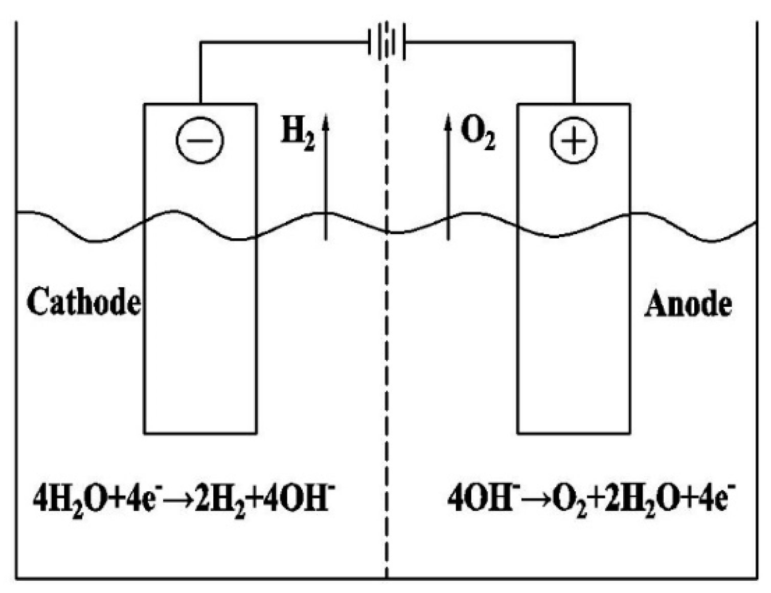
Figure 1. Schematic diagram of electrolysis of alkaline aqueous solution.
Energies 16 00086 g001
Figure 2. Schematic diagram of the structure of the experimental setup.
Energies 16 00086 g002
Figure 3. Schematic diagram of RMH structure.
Energies 16 00086 g003
Figure 4. The way the magnets are arranged in RMH.
Energies 16 00086 g004
Figure 5. Detection of voltage changes at different speeds.
Energies 16 00086 g005
Figure 6. Speed vs. voltage drop.
Energies 16 00086 g006
Figure 7. Hydrogen generation at different rotational speeds.
Energies 16 00086 g007
Figure 8. The pipes are moving in a magnetic field cutting magnetic induction lines.
Energies 16 00086 g008
Figure 9. Relationship between voltage fluctuation difference and current density difference.
Energies 16 00086 g009
Disclaimer/Publisher’s Note: The statements, opinions and data contained in all publications are solely those of the individual author(s) and contributor(s) and not of MDPI and/or the editor(s). MDPI and/or the editor(s) disclaim responsibility for any injury to people or property resulting from any ideas, methods, instructions or products referred to in the content.