Review

Review of Wireless Charging System: Magnetic Materials, Coil Configurations, Challenges, and Future Perspectives

by
Pradeep Vishnuram
1,
Suresh Panchanathan
1,
Narayanamoorthi Rajamanickam
1,
Vijayakumar Krishnasamy
1,
Mohit Bajaj
2,3,4,*,
Marian Piecha
5,
Vojtech Blazek
6 and
Lukas Prokop
6,*
1
Electric Vehicle Charging Research Centre, Department of Electrical and Electronics Engineering, SRM Institute of Science and Technology, Kattankuthur, Chennai 603203, India
2
Department of Electrical Engineering, Graphic Era (Deemed to be University), Dehradun 248002, India
3
Graphic Era Hill University, Dehradun 248002, India
4
Applied Science Research Center, Applied Science Private University, Amman 11937, Jordan
5
Ministry of Industry and Trade, 11015 Prague, Czech Republic
6
ENET Centre, VSB—Technical University of Ostrava, 70800 Ostrava, Czech Republic
*
Authors to whom correspondence should be addressed.
Energies 2023, 16(10), 4020; https://doi.org/10.3390/en16104020
Submission received: 21 February 2023 / Revised: 30 April 2023 / Accepted: 9 May 2023 / Published: 10 May 2023
(This article belongs to the Special Issue Wireless Charging System for Electric Vehicles)

Abstract

:
Electric transportation will assist in lowering emissions of greenhouse gases and mitigating the impact of rising petrol prices. To promote the widespread adoption of electric transportation, a diverse range of charging stations must be established in an atmosphere that is friendly to users. Wireless electric vehicle charging systems are a viable alternative technology that can charge electric vehicles (EVs) without any plug-in issues. Wireless power transfer (WPT), which involves the transmission of electricity via an electromagnetic field despite the presence of an intervening area, holds out the possibility of new prospects for EVs to increase environmentally responsible mobility. This review article examines the WPT technology and how it might be applied to electric vehicles from both a technical and safety standpoint. The prime aim of this review is (1) to illustrate the current state of the art in terms of technological advances as well as research limitations in the field of WPT development and use within the field of transportation; (2) to organise the experimental the deployment of WPT EV systems in the actual world; and (3) to analyse the results over a sustainable period and to identify limitations as well as chances for growth. From a technical point of view, the progress that has been made on the selection of material for designing coils, different types of coils with a specific focus on the overall performance of the system. As a result, this study aims to provide an extensive overview focusing on the magnetic materials and the architectures of the transmitter and receiver pads.

1. Introduction

The energy demand has risen at a startling rate in recent years, which is only anticipated to continue [1]. The most significant problem facing contemporary society is the rapid depletion of reserves of fossil fuels, as well as climate change, environmental problems, and ozone depletion. Because of this, increasing the proportion of renewable energy incorporated into our grid is essential to satisfy the ever-increasing demand for energy in the modern world. In 2005, non-renewable energy sources produced the vast majority of the total 17,450 TW of energy created. Over the last several decades, the excessive consumption of fossil fuels for energy generation has dramatically reduced availability. In addition to that, it is the root cause of a multitude of further environmental issues. The greenhouse effect is among the most critical issues that need to be handled, thus which brings us to the next point. Nuclear power may offer a solution to the problem of global warming. Still, environmentalists’ resistance to nuclear power has hardened in recent years due to fears about the possibility of terrorist attacks on earth-bound nuclear power plants.
The transportation industry uses many fossil fuels, making it the world’s most significant source of greenhouse gases (GHGs) [2]. It is necessary to develop alternative vehicle technologies to reduce reliance on fossil fuels and greenhouse gas emissions. Because of their benefits in terms of overall performance, reduced emissions, and increased safety, EVs are quickly becoming one of the most prominent options being researched right now. However, the acceptability of electric vehicles is closely related to the cost of purchase, the accessibility and efficiency of charging infrastructure, and the total driving range of the vehicle. According to the research that has been conducted, there are three distinct possibilities for electric vehicle supply equipment, often known as charging infrastructure [3]: (1) changing batteries, (2) inductive charging, and (3) wireless charging for electric vehicles. When a vehicle is involved in a scenario known as battery switching, the battery swapping stations, also known as BSSs, are set up to replace an empty battery with a battery that has been wholly charged [4]. This approach provides a quick method for recharging (i.e., the battery may be swapped out in fewer than 5 min). It enables variable time for charging, which can be relocated to an off-peak period if necessary. However, the effects of charging station swapping on the long-term health of batteries, the associated costs, and the stations’ practicability are still up for debate [4,5].
Although conductive charging technology provides a feasible and cost-effective solution, it has a long charging time (anywhere from 20 min to eight hours). It raises a few safety issues in harsh environments due to the heavy-duty cables and a few safety issues in harsh environments due to the heavy-duty cables that are exposed to the public [6,7,8]. The third choice is the wireless power transfer (WPT) technology, which allows an electric vehicle to be charged without needing any physical connection. This can occur whether the vehicle is parked for an extended period (stationary). At the same time, it is being driven (dynamic or in motion), or during brief stops (quasi-dynamic or opportunistic). Because it is automatic, easy, reliable in harsh environments, durable against trespassing, and may be implemented on the road, in public parking, private parking, and at bus stops, wireless charging offers a perfect option for EV charging [9,10,11]. Wireless charging technology is an ideal solution for EV imposing because of all of these reasons. In addition, the implementation of in-motion wireless charging technology has a chance to provide an unlimited range for driving and zero downtime, as well as a dramatic reduction in the size of the onboard battery. This results in a lower price, smaller size, lighter weight for electric vehicles, and improved operational efficiency [12]. The technology of wireless charging has an opportunity to hasten the adoption of electric vehicles, which in turn leads to an improvement improved life for people today and an improved world for generations to come [13].
The first evidence of wireless power transfer occurred in the late 18th century [14,15,16] when Hertz demonstrated the propagation of electromagnetic radiation in space using a spark gap [17]. This was the first time that wireless power transmission was successfully proven. Nicola Tesla conducted experiments to see if transmitting electricity wirelessly via radio waves was possible in 1890. Between the years 1894 and 1918, he constructed the Tesla tower, which was a massive coil with a cop in the year 1960, William Brown came up with the idea for a device that would wirelessly transport solar power into space so that it could be utilized to power spacecraft [18,19] per ball on the top, to use electrostatic induction to transport power wirelessly [18]. In the period between 2007 and 2013, a team of researchers from the Massachusetts Institute of Technology (MIT) introduced Tesla’s theories and experiments that were based on magnetic resonance coupling to wirelessly transport 60 W across a distance of 2 m with an efficiency of 40% utilising coils with a diameter of 0.6 m [20,21]. Since then, several research groups worldwide have begun investigating the WPT system for various applications, including electric vehicles, consumer gadgets, cell phones, computers, home appliances, medical equipment, and electric machinery.
Several reviews of the IPT system have been published in the relevant academic literature [5,6,7,13,20,22]. The majority of this research concentrated on providing a general description of the technology, including various coil structures [16,22], various compensation settings [16], visions of electric vehicle charging via Bluetooth [20], and historical data [11]. A comparison of electric vehicles’ conduction and wireless charging capabilities was published in [6], considering the different types of EVs, power levels, advantages, limitations, and plans for the industry. In [23], an overview of electrical charging technology was offered, in which several charging methodologies and related standards were reviewed. The possibilities of utilising inductive charging technology for electric vehicles were studied in [24], with dynamic as static wetland charging being considered the best of the author’s knowledge. There is not yet a review study that concentrates on the layout of the inductive pad and describes in detail the components (wires, core, and shield) and substances that have been described. As a result, this article provides an exhaustive and specific review of each part of the wireless charging pad, specifically the transmitter, and receiver. It investigates as well as contrasts:
The magnetic material used for transmitter coil design.
Various electromagnetic shielding.
Various inductive pad architecture with its sustainability
Issues in the wireless charging system
In addition, this study sheds light on several different wireless power systems and discusses the properties of those technologies. This study gives an overview of the research conducted on WPT, which can assist researchers in identifying substantial gaps in the methodologies currently being used and attracting prospects.
The organization of the paper is carried out as follows. Section 2 deals with WPT Magnetic material and coil design. Electromagnetic field shielding is explained in Section 3. Inductive pad architectures and their electromagnetic standards, wireless charging system sustainability, and social impacts have been described in Section 4 and Section 5, respectively. The issues in wireless charging and future perspective are summarized in Section 6 and Section 7, respectively. The overall conclusion of the article is enumerated in Section 8.

2. Magnetic Material and Coil Design

2.1. An Overview of Soft Magnetic Materials

Michael Faraday discovered in 1831 through an experiment that a current would be generated in the conductors of a closed circuit whenever a section of the conductor cut the magnetization line inside the magnetic field. Michael Faraday discovered this. It was suggested that Faraday’s law of induction should be used [25]. Because it has the largest saturation magnetization of any element, iron is selected to serve as the core of the magnetic structure. In addition, it possesses the qualities of solid permeability and minimal coercivity, both advantageous. Since that time, continuous progress has been made in soft magnetic materials. The researchers then observed that the recrystallization of iron could increase its mechanical properties and reduce its coercivity through a process known as stress relaxation. This was confirmed to be the case after the previous finding. As a result, iron is now more suited for use in applications that involve induction.
British metallurgist Robert Hudfield invented quasi-silicon steel in 1900 by adding 3% silicon to the iron. This enhanced the material’s resistivity and saturation magnetization [26]. Grain-oriented silicon steel was invented in 1933 by American metallurgist Norman Goss. To achieve this result, he favoured grain growth in the direction of low anisotropic crystallization, leading to higher saturation magnetisation levels [27]. Even today, silicon steel remains the dominant player in the international market for soft magnets due to its high magnetic moment and comparatively low price. Large transformers made out of orientated silicon steel are the most prevalent application for silicon steel, followed closely by motors (isotropic non-oriented silicon steel). Silicon steel, on the other hand, loses more energy at higher frequencies due to its low resistivity (0.5 mΩ m) [21]. With a procedure involving chemical vapour deposition, manufacturers of electrical steel have recently devised a technology that allows for an increase in the silicon content of the steel to 6.5% [28]. Although this technique can potentially bring silicon steel materials up to 82 μΩ cm resistance, it is not yet capable of meeting the high-efficiency needs of high-frequency power electronics and high-speed motors.
Gustav Elmen of Bell Labs conducted work in the 1910s on nickel-iron, which led to the discovery of the nickel-rich (78%) permalloy mixture [29]. One of the permalloy’s most notable benefits is its high relative permeability (up to 100,000). Nickel-iron is still utilized in a few unique induction applications in today’s modern world; however, due to its significant eddy current loss, nickel-iron is not typically utilized in power electronics or motors. Adding nickel can decrease soft magnetic materials’ saturation magnetic flux density. Moly based on different parameters powder (MPP) could be created by incorporating 2% molybdenum into the permalloy manufacturing process, as stated in [30]. MPP is utilized to fabricate the powdered cores with a minor loss [31], and it remains the best option for high-frequency inductance cores inside the frequency band of 450 kHz and above.
Then, towards the end of the 1940s, J. L. Snoek developed soft magnetic ferrites [32]. Due to the high resistivity of these materials, they can effectively reduce eddy current loss. In addition, preparing ferrite is often relatively straightforward, allowing the ferrite core to be manufactured at a competitive price. Soft ferrite is increasingly used in electromagnetism and high-frequency equipment because it has a high resistivity and good economic performance. Nowadays, ferrite is second only to silicon steel sheets regarding market share among soft magnetic materials worldwide [33]. The WPT system also extensively uses manganese zinc ferrite, making it the most popular soft magnetic material. However, the power density of sensor devices containing ferrite cores is constrained by ferrite’s low saturation flux density (almost a fraction of Si steel sheets). Because of this, the progression of the ferrimagnetic process has always been aimed at raising the high saturation flux of soft ferrite.
The very first polymorphic soft magnetic alloy was described by Duwez and Lin in the form of disc-shaped samples [34] in 1967. To solidify Fe-P-C systems quickly, they adopted a process termed splat cooling. By the middle of the 1970s, interest had risen in amorphous alloys based on Fe and Co. The higher coercivity and maximum magnetic density of amorphous alloys compared to ferrite led to their adoption in several practical contexts. Compared to ferrite, amorphous alloys have better conductivity and saturation magnetic density, giving them some uses. In 1988, Hitachi researchers indicated Nb and Cu and added an annealing step to making amorphous alloys. This made small iron or cobalt-based nanomaterials (about 10 nm in diameter) that were evenly distributed in the amorphous materials. This was the first time nanocrystalline alloys were made [35]. Nanocomposite and nano-crystalline alloys have reduced power loss and a competitive concentration flux density. Even though they cost more than silicon steel, these advanced alloys can lower the cost of power electronics and motors over their lifetimes because they lose less power.
By the beginning of the 1990s, the concept of powder cores, commonly referred to as magnetic materials composite or SMCs, was put forward [36]. These materials begin with magnetic particles ranging in diameter from 0.1 mm to 500 mm. They then coat or mix those with an insulating layer before solidifying them under high pressure. In addition, the heating procedure can be utilised either during or after the densification stage to enhance the magnetic characteristics of the material. The iron powder that makes up magnetic particles is almost always present, although magnetic particles can also be made of alloys. Powder magnetic core can be easily treated into a more complicated shape, increasing its usability in specialized equipment and significantly reducing manufacturing costs. SMC has found much use in spinning electrical machines because of its isotropy, low cost, and ability to manufacture intricate mesh sections [37,38]. Even though the magnetism of the powder core is often quite low, its stability at high frequencies is quite remarkable (such as the MPP mentioned earlier). Regarding high-frequency inductor design, magnetic cores based on SMC are a desirable option. Changing the powder size, adding insulating materials and phosphoric acid, and increasing the pressure during preparation can help achieve an SMC core’s desired total core permeability. This helps reduce the air gap loss and simplifies the inductor design [39].

2.2. Wireless Charging

The use of near-field magnetic coupling is shown in Figure 1, by which a non-ionizing radiative wireless charging system for electric cars may function. The utility side alternating current (AC) is turned around and amplified in a conductive charging system which makes direct current (DC) power with a power factor close to 1.0. The Buck stage lowers the DC voltage. The charger’s start/stop can be made as “soft” as possible. Its output power can be fine-tuned indefinitely because of the BUCK stage’s adjustable output voltage, which can be set between 0.03% and 0.97% of its input voltage. In this case, the buck stage is not required because the “soft” start of the charger can be accomplished with just a pre-charge circuit consisting of two relay contacts with one resistor, and the “soft” stop of the charger may be achieved with a phase-shift approach in the inverter stage. A wireless charging system’s overall cost and size can be reduced by replacing the buck stage with a pre-charge circuit and the phase-shift method.
During the inversion stage, direct current (DC) electricity is changed into high-frequency alternating current (HFAC) so that it can be synchronized to the switching frequency of the inverter. The primary compensation circuit and coil reflect this high-frequency alternating current power. Even without a wired connection between the secondary and primary coils, it can still receive HFAC power because of their mutual inductance. The secondary compensation network and the secondary coil are tuned to the same resonant frequency for higher efficiency levels. It is then passed through a rectifier step, the HFAC power is converted to DC power, and the filter network removes unwanted ripple. Now DC power is ready to charge the battery pack. The critical areas of focus for research into wireless charging include the design of the charging coil, some compensation networks, power electronics converters, and control techniques.
The inductive coupler, which is a part of the IPT system and is in charge of transferring energy from the source to the vehicle, is the most sensitive component of the system. This responsibility makes it one of the system’s primary focuses. As shown in Figure 2, it is primarily made up of two pads, one for the transmitter and one for the receiver. Each pad contains three primary components: conducting wires with a tray, magnetic core, and shield. The existing body of research offers a wealth of knowledge on core selection and coil design, which will be discussed in the paper.

2.3. Core Design

The inductive coupler, which is a part of the inductive power transfer (IPT) system and is in charge of transferring energy from the source to the vehicle, is the most sensitive component of the system. This responsibility makes it one of the system’s primary focuses. Because the intensity of field lines substantially decreases with increasing distance, these loops have a restricted travel distance. Due to its inherent characteristics, IPT technology is severely constrained in its ability to transmit electricity over considerable distances (more than one meter). On the other hand, this feature makes the device safer regarding the electromagnetic fields that may leak out surrounding it. IPT systems often use specialized flux concentrators to focus the fluxes created from the transmitter towards the receiver [40]. These flux concentrators aid in improving its performance as well as the efficiency of the system. It decreases the amount of flux that leaks out around the system. For the system to meet the standard safety limitations, straightforward shielding is required, which will reduce the leakage flux. Additionally, the negative effect that the shield will have on the performance of the system will be negligible [41]. The research about the core design, such as the material, shape, and measurements discussed in this part, can be found across the relevant published works.

2.3.1. Air Core

As a result, the IPT system, in this instance, is intended to operate without any flux concentrator. Figure 3 shows flux passing through the air. This technique will make the IPT system less expensive, have a lower overall weight, and be easier to design and integrate. In addition to this, it removes the losses that come with a magnetic core. However, considering air-core coils necessitates the utilization of additional turns within the system, increasing both cost and winding loss [42].
Additionally, due to significant influence, the air-core coil can realize a more skin effect and the proximity effect the same as EMF fields [43,44,45]. The massive amount of winding loss incurred in the air-core coil is more significant than those of solenoids due to excessive winding losses for reducing the core losses. Due to this limitation, air-core coils are not recommended in large power IPT systems [43,46,47].

2.3.2. Ferrite Core

IPT systems that charge electric vehicles most frequently use a ferrite core. Ferrite is a ceramic material produced by combining significant portions of FeO3 with insignificant portions of more than one metal, such as nickel, zinc, and barium, and then heating the resulting mixture [47]. Ferrite is a nonconductive type of ferromagnetic substance (an insulator) and can be easily magnetized and attracted by a magnet [48]. Hard ferrite and soft ferrite are distinct types that can be distinguished from one another according to their resistance to demagnetization. The first type is famous for making permanent magnets for lower-power motors because of its coercive solid and low demagnetizing ability [49]. As a result, the soft ferrite n’s low coercively may be magnetized and demagnetized with relative ease, and it also acts as a conductor for electric flux [50]. In manufacturing, soft ferrite is utilized to create magnetic ferrite cores that are efficient for HF inductors and transformers [51]. Mn Zn and Ni Zn are the soft ferrites utilized most frequently in IPT systems due to the relatively modest losses they experience at high frequencies [52]. They have a high magnetic permeability and a low electrical conductivity, reducing eddy currents.
A ferromagnetic core is usually added for the transmitting and receiving coil. More studies investigated how ferrite affects the mutual inductance of the system, power transfer capacity, and efficiency [53,54]. The ferrites at the primary coil were switched out for a second parasitic coil positioned beneath the primary coil to enhance the shielding performance while slightly lowering the transmission efficiency. This retrogression relies on the space separating the parasitic coil and the primary transmitter from another total number of parasitic coils. The effectiveness rises in direct proportion to the square of the distance that separates these two coils [55].
In most cases, the ferrite material’s core comprises individual ferrite blocks assembled in a specific pattern to produce the core. These blocks can be shaped similar to an I [46,56], a rectangle [57,58], or a square [53,57,59]. The pad’s structure will dictate, to some extent, the form that the eventual core will take (rectangular, circular, D-D, double-DQ, and QDQ). However, depending on the construction of the pad, the shape of the ferrite core can be one of three different things: a single plat [53,54,55,60,61], many bars [46,57,61,62,63], or discrete tiles [64,65]. Table 1 lays out these three distinct possibilities for consideration. The authors of [66,67] recommended utilizing two ferrite layers stacked on each other. They also examined how the coupling factors would affect the system’s performance when both inductances were incorporated. Properly adding ferrite components in an IPT may be crucial for aligning the flux lines, lowering the amount of leakage flux, improving coupling and performance, and making the system conform to the specified range for electromagnetic fields [57]. However, using ferrite raises prices, making things heavier and more likely to break. Ferrite is also more challenging to clean.

2.3.3. Nanoparticle Core

Even though ferrite cores exhibit excellent performance in IPT systems, the presence of these cores does cause some limits. Due to the displacement and pressures the road and automobiles create, ferrites are brittle and easily broken. Additionally, due to their high density, ferrites contribute to an increase in both the vehicle’s mass and its overall energy consumption. Generally, ferrite materials have a low saturation level which restricts the power transfer ability, particularly in high power circumstances. As a result, several studies looked into potential replacements for ferrites that were more effective. A material consisting of ferromagnetic nanoparticles is suggested for use in the IPT system [68,69,70]. These nanoparticles can be combined with a polymer particle to strengthen their magnetic properties and withstand mechanical shocks. In [71], an additional nanocomposite thin film for the IPT system was proposed. This film demonstrates increased magnetic permeability in comparison to ferrite. Including particles can decrease the system’s weight, boost power transfer, and improve the shield performance while having less of an effect on the efficiency and improved shielding performance [72]. However, they are exceedingly delicate and expensive, contributing to the IPT system’s overall weakness and making it easy to break.

2.3.4. Flexible Magnetic Material Core

There was some discussion in [73,74] about utilizing movable magnetic cores for the IPT system. The electrodeposition method, distinguished by its simple application, low cost, and precise pattern control, can make this material relatively simple. NiFe soft magnetic material, which showed increased permeability and less resistance than other permanent magnets, including FeHfN and CoNbZr, was recommended as a material for a flexible core [75]. Because of these qualities, there is a reduction in core losses and an improvement in quality factors. A parylene substrate has been added to the compound to make the NiFe more flexible and improve its biocompatibility. The flexible core’s resistance to physical loading and disturbance increases the system’s resilience.

2.3.5. Concrete Magnetic Core

Employing flexible cores, magnetic nanoparticles, and ferrite in the vehicle pad is more convenient than using other cores. However, the transmitter pad cannot be put or buried in the road because none of the materials is suitable. The transmitter pad is susceptible to harm from any cracks in the road. As a result, in [76], a magnetizable concrete was produced and proposed to be used in the transmitter. This concrete is a composite material that can be cemented with magnetic particles in varying mixed proportions. The volumetric ratios of the two components can vary. Magnetic concrete is flexible and possesses excellent mechanical capabilities [77]. It is also compatible with the road. Because the magnetic particles are reusable, the cost is negligible. The research was conducted to understand better how magnetizable concrete compares to ferrites in terms of its permeability and mechanical properties [77]. In [78,79], the effectiveness of an IPT system taking magnetizable concrete into account was studied and compared to that of a ferrite-based system.
In light of this explanation, Table 2 compares the various soft magnetic materials that could be used in an IPT system. Researchers and manufacturers may benefit from comparing all materials regarding magnetic flux density (B), magnetic field density (H), relative permeability (µr), and critical temperature (Tc).

3. Electromagnetic Field Shielding

Inductive power transfer is used in EV chargers to transfer a considerable amount of power (up to several hundred kilowatts) across a long distance. The result is that when charging, significant EMFs are often produced in the vicinity of the system. International norms and guidelines [80,81] indicate that these fields may exceed acceptable levels. Shielding against EMFs is commonly employed in IPT systems for reducing the flux leakage of the overall system, enhancing the coupling interpretation, and raising quality and efficiency factors [82,83]. Several protective shielding is documented in the literature, including active, passive, and conductive [84,85,86,87].

3.1. Passive Shielding

Using a passive component (either magnetic or a conductor) that assists in blocking and/or shaping electromagnetic field (EMF) for the reduction in flux leakage in a system. Magnetic passive shields are made from very high permeability and nonconductive materials. Its purpose is to glide the magnetic lines to travel through a particular path, which can improve system performance, increase self and mutual inductance, and decrease leakage flux [41,88]. The electromagnetic shield is created by a magnetic core inserted into the pad. This magnetic core can be a plate, numerous bars, or multiple tiles. The magnetic core implanted in the pad provides the magnetic shield, and this core can take the form of a plate, a series of bars, or a collection of tiles. As shown in Figure 4, a magnetic shield can be designed into an inductive pad using a ferrite core, as illustrated in Figure 4a. The leakage flux can be reduced by adding a magnetic loop around the coil, as suggested in [88]. Considering matching DD coils, this looping minimised emissions by 60%. Employing permanent magnets for shielding achieves good results but adds bulk and expense to the overall system. Therefore, a different path was taken, using fewer magnetic components in the system to concentrate flux and incorporating a lighter, cheaper conductor to keep EMFs within safe parameters. Therefore, it is becoming more common in IPT system design to pair magnetism with a conductive active or passive shield [65,84,89]. When it comes to the magnetic core of the transmitter, the conductive passive shield is installed below it, but when it comes to the magnetic core of the receivers, it is installed above it. This is depicted in Figure 4b, and examples of conductive passive shields include copper and aluminium [83,90]. If the coil has an air core, it can also be coupled directly to the coil, as depicted in Figure 4c. These conducting plates function as secondary coils and are where the eddy current is produced by HF electromagnetic fields [91].

3.2. Active Shielding

When considering traditional passive shielding [88], it is incredibly challenging to effectively regulate the leakage electromagnetic fields (EMFs) surrounding the vehicle that is produced by high-power IPT systems (more than 100 kW) and to maintain these EMFs below the safe limits. Because active shielding is a more effective method, it was explored to see if it could be used for the IPT system [86]. For this configuration, as shown in Figure 4d, the wire is coiled more tightly and twisted anticlockwise at its poles. By routing the same current through the shielding turns as the original coils, it is possible to intentionally generate electromagnetic fields (EMFs) with the same frequency and magnitude as the initial fields but in a negative direction [89,92], thus reducing the number of leakage EMFs. While this variant’s shielding performance is superior to the passive variant, it has a much more detrimental effect on the system’s original field and overall performance. Additionally, the cost of the system, the weight, and the coil losses all rise with each additional turn. Two types of shielding are used with a magnetic one: the passive conductor and the active shield [89].

3.3. Reactive Shielding

The resonant responsive shield was presented in [87,89,92] to mitigate the active shield’s detrimental effects on system performance. As shown in Figure 4e, it depends on employing a passive compensating loop coil coupled with a resonance capacitor. Generating an intentional opposing field of this type does not necessitate external power. To counteract this, an additional shield coil is placed near the primary coil and wound to produce an induced voltage whenever the primary magnetism passes through the shielding coil. This, in turn, generates a high-frequency (HF) current in the shield coil, which oppositely produces a magnetic field. Compared to the active shield situation, the system’s efficiency in this scenario is higher [92].
In conclusion, passive types of shields are suitable for both low and medium-power IPT systems to reduce EMFs to a safer level. Moreover, they are less expensive, easier to install, and more reliable [41]. Reactive and active shielding is more likely to bring a high-power IPT system into compliance with the established limits of EMFs [84,89].

4. Inductive Pad Architectures and Electromagnetic Standards

4.1. Various Inductive Pad Architectures

The construction of an inductive coupling pad is defined by combining its three major elements: the coil, the core, and the shield. When defining the performance of an IPT system based on coupling factor, efficacy, sensitivity to misalignment, and safety [93], this structure plays a very significant role. E-cores [94], U-cores [94,95], and pot cores [96,97] were some of the classic shapes that were initially explored for use in the IPT system. These structures are typical in the transformer business and are used rather frequently. These designs exhibit performance incompatible with EV applications due to their high cost, fragile structure, heavyweight, and susceptibility to horizontal misalignment [98]. In [62,99,100,101,102], it was suggested that planar pad architectures might be used to address these issues. For reducing thickness, size, and weight while reducing the system’s sensitivity to misalignment in all pad dimensions, the coil, core, and shield are appropriately designed and positioned. These are all crucial features of an IPT system. As a bonus, most of the structures exhibit well-matched operation between one another, allowing any charger regardless of the electric vehicle or manufacturer’s restrictions [99,100,101,102,103,104].
The presence or absence of a polarising component in the linked flux distinguishes non-polarized (NPP) and polarised planner (PP) pads. The former uses only one coil to transfer the necessary power to produce any vertical flux connected to the receiver coil. Here rectangular pads and circular pads fall under this category, and the other type, known as polarized pads, generates horizontal and vertical fluxes. All of these components are linked with the coil on the receiver side to transfer power. In most cases, PP is made up of many coils, namely D-D quadrature (DDQ), D-D (DD), and bipolar pad (BP) [99]. Most pad types of architectures, such as CP, RP, and DD, can operate as both a transmitter and a receiver pad.
On the other hand, specific structures are better suited for the transmission side, such as CP, processing system pad (HP) [100], and DD [101]. Examples of these structures include DDQ [101] and BP for compatibility purposes [102]. Most of the pad-based structures documented in the prior study are summarised, and the comparison is made in Table 3, Table 4, Table 5, Table 6, Table 7 and Table 8. The comparison is made based on the parameters such as shape, coupling performance, misalignment tolerance range, the ability of shielding, level of polarization, compatibility, and magnetic flux. The pad constructions for one coil are shown in Table 3 and Table 4, while the polarised configurations for two coils are shown in Table 5. Three-coil-based constructions are shown in Table 6, while multi-coil layouts are presented in Table 7 and Table 8.

4.2. Electromagnetic Standards

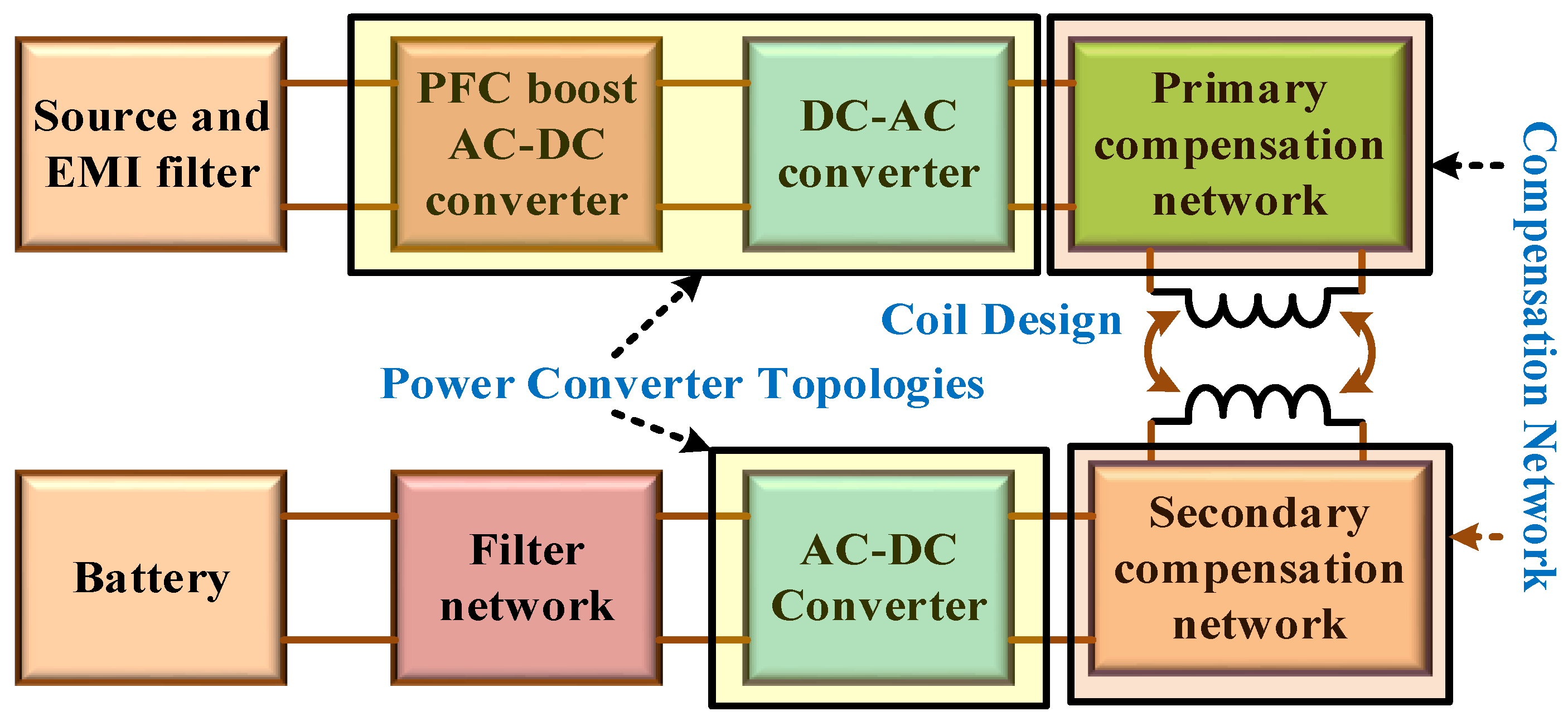
Using the terminology provided by SAE RP J2954, a typical WPT system comprises a ground assembly (GA), also known as a transmitting circuit, and a vehicle assembly (VA), known as receiving. Together, these two components make up the WPT system. The electrical component and the coil are the two components that makeup both the GA and the VA. The electronics unit of the GA includes all of the parts essential for converting power from the AC electrical network quantity into the electrical supply required by the gearbox coil at a high frequency. This conversion takes place within the electronic unit. These components comprise a high-frequency converter for the DC conversion into AC compensation capacitors and a power factor correction (PFC) converter to rectify and modify the magnitude and the input voltage. The PFC conversion may rectify and adjust both the magnitude and the input voltage. The electrical unit of the VA has a battery charger, compensation capacitors, and a rectifier for transforming alternating current to direct current. All of these components are used to convert AC to DC.
WPT standards set the nominal operating frequency at f = 85 kHz (tuning band 81.38 to 90 kHz), and SAE divides the permissible power levels for light-duty vehicles into four classes: 3.7 kVA, 7.7 kVA, 11.1 kVA, and 22 kVA. WPT standards fix the nominal operational frequency. Furthermore, the efficiency standard is fixed as greater than 85% for aligned coils and greater than 80% for unaligned coils.
As the coupling factor k reduces and ground clearance increases, the vertical separation between the GA and VA coils becomes increasingly significant. Therefore, to classify the WPT systems according to the anticipated maximum ground clearance, three Z-classes have been defined as 100–150 mm, 140–210 mm, and 170–250 mm. In addition, the offset position is standardised concerning the optimal position, which corresponds with the centres of round GA and VA coils whenever they are aligned. This optimal position was determined by comparing the offset and optimal positions. Once the coils have been in their ideal position, the WPT system can function at its highest efficiency level. In the lateral direction, the maximum permissible offset is ±100 mm, and the fore and aft direction is ±75 mm.
In practice, the grounding coil will be installed on the floor as well as the VA coil will be installed in the undercarriage of the vehicle; however, this configuration is not set in stone and is subject to change based on the WPT level of the EV imposing system, the clearance from the ground that varies depending on the type of vehicle and the vehicle’s weight, and the offset place due to a vague parking job. Any deviation from the ideal position causes a reduction in the coupling factor k, which in turn causes an increase in the emission of magnetic fields. Other parameters that have a crucial effect on the dispersion of the magnetic field include the dimensions and shape of the EV bodyshell and the material it is made of. The zone beside the car, just a few feet from the ground, is the most critical location for EMF safety (except the entire space below the vehicle, secured by a security system). This is because the entire area below the vehicle is protected. For each WPT class, the field’s magnetic strength is most significant for most miniature vehicles with the greatest possible ground clearance and offset.

5. Wireless Charging System Sustainability and Social Impacts

The WPT is beneficial for wirelessly charging electric vehicles (EVs). The world’s most significant pollution source today comes from automobiles powered by gasoline and diesel engines as well as large machinery that runs on diesel fuel. The following part will clarify any preconceptions regarding specific health, economic, and environmental concerns.

5.1. Energy and Environmental Reckoning

Wireless EV charging preserves the environment in two stages. Let us take into account all of the systems that are capable of being driven by electric power. The utilisation of electrical power rather than gasoline or diesel engines is the preferred option. The most significant advantage they offer is that electrical equipment does not directly pollute the environment. Nonetheless, there is an issue with the capacity of electrical equipment to store electricity. Hence, WPT will operate that equipment wirelessly, or if the battery is used for driving the machine, it will utilise WPT, which can be readily charged since batteries are used for driving the machine. WPT decreases the battery’s load by wirelessly operating the device, reducing the system’s overall weight. Brown investigated the plug-in and wirelessly powered systems at the University of Michigan [141] using a 12-year framework analysis to make comparability. Two conclusions emerged.
  • WPT systems reduce the need for batteries, which can compensate for the GHG emissions and extra energy the wireless charging infrastructure needs.
  • Reducing the size and weight of the battery will cover the extra costs of installing a wireless system.
There is a significant gap in the range of power transmission between plug-in charging, also known as power transfer, and when comparing the technological development of these two charging methods. Yet, it is evident that WPT is far more practical, secure, and environmentally friendly in contrast. Researchers have claimed that in the future, power transmission up to metres will make sustainable mobility better by cutting down on the use of cables and batteries.

5.2. Economic and Policy Analysis

The charging infrastructure, the battery, and the phase energy cost [142] are the three primary components of WPT technology’s product life cycle that compete with those of other technologies. Compared to the cost of a wired electric vehicle charger, the wireless charging system only requires two magnetic couplers, the only additional component utilised in the system. This will lead to an additional material cost of around $400 US dollars for the 8-kW charger [143]. Because the charger has such a long life, this price is reasonable due to its added convenience. Compared to diesel buses, wireless buses can experience a reduction in fuel costs of approximately US $90,000, or up to 80%, throughout the vehicle’s lifetime [144]. Comparing the cost of maintaining a wireless charging system with that of a wired system shows that the wireless system’s maintenance costs are lower. This is because there is no physical contact between the transmitter and the receiver. The battery is the primary concern regarding the cost of the wireless charging system. The required onboard battery power will decrease if there are sufficient charging stations and vice versa. The cost functions for wireless charging come in two different forms. The first is the cost function for the battery, and the second is the transmitter’s cost function. Two costs are associated with the power transmitter function: (1) The cost of the transmitter varies based on its length (2). The cost of the inverter and the labour price to connect to the grid makes up the fixed cost.

5.3. Health and Safety

When it comes to the extensive use of electric vehicle wireless charging, the first issue that needs to be answered is “is it safe for health?”. This is primarily because people are concerned about the electromagnetic field that is created when wireless power is transmitted. Eric Giler [145] states that WPT is a significantly safer alternative to the radiation emitted by cell phones. When Moon et al. adopted [146] a double shielding coil and four capacitors to minimise the amount of wasted magnetic flux, they proposed using a phase shifter for shielding. This double-shielding coil generates an opposing field, which effectively nullifies the effect of the leakage flux. The IEEE and ICNIRP have imposed limits on the intensity, frequency, and other aspects of electromagnetic radiations and fields employed in wireless applications. The main objective of this standard is to establish exposure limits that will protect people from the known harmful effects of electromagnetic waves on human health when exposed to radiofrequency electric, magnetic, and electromagnetic fields in the frequency range [147] of 3 kHz–300 GHz. These fields can induce these effects. Researchers are working to develop a barrier that can protect against electromagnetic fields. Excessive exposure to electromagnetic radiation can cause a variety of health ailments. The chronic exposure reference level is determined based on the conditions of maximum coupling of the field to the individual exposed to it. This calculation considers the central nervous system influence and the peripheral nervous system effect. Between 25 Hz and 10 MHz constitutes the basic reference level for occupational exposure to electric fields.
Various electrical, chemical, and thermal dangers, as well as dangers posed by components of an EV that have been damaged, are included among the hazards posed by EVs. Using a hazard rating as a framework, an assessment of the dangers of electric vehicles is carried out. The battery, the wiring, the brakes, and other components are the most typical causes of accidents. These potential dangers could result in a wide variety of incidents, including fires and explosions, as well as mishaps on the road and many more. Because of the inherent dangers of electric vehicles, it is crucial to take a cursory look at each of these aspects to ensure that EVs can function effectively while incorporating any necessary upgrades [148].
The lithium-ion battery, an essential part of an electric vehicle, is also the source of the most common risk associated with these vehicles. The exceptional performance of lithium-ion batteries has led to their widespread use in electric vehicles (EVs); yet, continual fires and explosions have limited the applications for which they may be employed. The scope of improvement that can be made in lithium-ion is primarily connected to cell safety, which covers cell chemistry, cooling and balancing, and some of the existing safety regulations. It is possible that the fundamental qualities of lithium-ion batteries, such as their high specific capacity and voltage, lack of memory, low level of self-discharge, and broad temperature range of operation, could make lithium-ion batteries less safe than other types of rechargeable batteries [149]. The unstable electrolytic system is mostly to blame for the failure of the lithium-ion battery. Voltage and temperature are the two factors that influence the many processes inside a battery. The constant production of heat and gas causes wear and tear on the battery and the igniting of combustible items. The battery’s performance might be impacted by the surrounding environment as well. Many different kinds of research have been conducted, and the work that has been carried out has been released covering the safety of battery-related problems such as electrolytes, the materials of cathode and anode, improved batteries, and battery thermal runaway difficulties as well as other related topics [150]. Altering the cell’s internal chemistry, enhancing a cell’s cooling mechanism, and rebalancing the cells are some of the other potential methods that have been suggested for enhancing the battery’s safety under any given circumstance.
When an accident happens involving an electric vehicle (EV), it is far too risky and unsafe to touch the EV since it has high-voltage integrated components. This is the primary reason for the electrical risks in EVs. An electric vehicle’s voltages are far higher than a typical protection voltage. Therefore, when developing an electric vehicle, considerable thought should be given to the electrical dangers, as the vehicle must be secure from electrical hazards. Various technical safeguards, such as the high-voltage interlock mechanism and the insulation tracking of the energy storage system, can ensure an electric vehicle’s protection from unanticipated dangers. All high-voltage electrical components have been built so that the risk of injury that can be induced by touching them can be eliminated. These components are galvanically insulated from the low-voltage system and the rest of the vehicle’s body.
Chemical risks are the most common kind of hazards that can be generated by an electric vehicle, and they are caused when hydrocarbon and hydrogen fluorides are released into the atmosphere. When these compounds come into touch with a human being via inhaling, they unleash their potentially lethal effects. If the system does not have a proper venting mechanism, the hydrocarbons that discharge from the cell can potentially catch fire, which might lead to a large explosion. In a similar vein, hydrogen fluorides, which are produced when a battery catches fire, are a potential hazard.
When the temperature is considered, the potential for thermal risks in an electric vehicle becomes apparent. Some chemical processes may occur within a lithium-ion battery cell if the cells are subjected to temperatures significantly higher than their normal working temperature range, which does not often go over sixty degrees Celsius. Because these reactions are exothermic, the cell loses a significant quantity of heat, which might lead to thermal dangers if the cell is not adequately protected. If one of the battery’s cells experiences thermal runaway, the high temperature produced by that cell will cause damage to any adjacent cells that it is in contact with. Because it involves an exothermic reaction during the decomposition process, this process, which is brought on because of the thermal runaway in an EV, is difficult to stop [148].
The issue of an EV’s relatively low level of background noise is the one that presents the most significant prevalence of risk. The low noise produced by an electric vehicle has two sides: an advantage and a loss that arises. The advantage of low noise is essential since it is related to the environment and helps minimise the noise pollution created due to undesired noises from automobiles. On the other hand, there is a possibility of putting one’s life in danger when driving an electric vehicle on public highways because of the relatively quiet vehicle operation at moderate speeds. When pedestrians try to cross the street in metropolitan areas, they frequently find themselves in precarious situations since it can be difficult for them to pick up on the sound coming from EVs. As a result, they run the risk of being wounded. When travelling at low speeds in an EV, the engine fails to produce any sound; as a result, it is difficult to identify the car. Therefore, the lack of sound may lead to accidents that cannot be avoided when using an electric vehicle [151].
While charging an electric vehicle in a garage, within the house, or at a public recharging station, the vehicle can catch fire, resulting in serious injuries or even fatalities. Other ways an electric vehicle might become dangerous include the following: If a technician makes a mistake when repairing an EV, the EV can experience a short circuit as a result. Accidents can happen when adjusting the level of an electric vehicle (EV) because of the potential for harmful situations, such as when the jack becomes lost and accidentally pushes the high-voltage battery. Because an EV contains so many different electrical components, there is a small but real risk of starting a fire when placed onto a tow truck [148].

6. Issues in Wireless Charging

In [152,153], describe the problems now occurring with WPT and the rules that aim to eliminate them. One of the most significant challenges related to wireless power density is its difficulty quantifying. However, there is limited control over it due to the signals from other sources being reflected and refracted. Furthermore, problematic is the planning of power transfer for ETs, which must be conducted to optimise power transfer and maintain EMR safety [154]. Third, the unexpected movement of ER is an issue regarding appropriate technology.
The utilized frequency range by modern WPT systems is within the vicinity of 2.4 or 5.79 GHz. Within the ITU-R radio regulation, this band is already designated for use by various radio services. For instance, radio local area networks and microwave ovens operate on the 2.4 GHz frequency, while the 5.79 GHz frequency is used for DSRC-devoted short-range communication. There is a possibility that WPT will affect these services [155].
The microwaves utilized by MPT are of significantly higher intensity than those utilized by wireless communication systems. Therefore, it is essential to keep human safety in mind while operating such devices [156]. The value of the SAR, or specific rate of absorption, for the most realistic effect, is the benchmark used to determine whether or not a microwave is dangerous. SAR considers heat. Hence, it is helpful because of its higher relevance to potentially harmful for the eyes [157].
According to the International Commission on Non-Ionizing Radiation Protection (ICNIRP), the threshold value for individuals and the general public, respectively, is either 50 or 10 W/m2, regardless of whether the frequency is 2.4 or 5 GHz [158]. The ICNIRP has set a limit of 50 W/m2 at 2.4 GHz and 5 GHz for people exposed on the job and 10 W/m2 for the general population, respectively [158]. Furthermore, according to IEEE standards, the average power density over six minutes is 81.59 or 100 W/m2, and over thirty minutes, it is 16.3 or 38.7 W/m2 [159]. Developing and using wireless power transmission technology across various industries requires first addressing safety concerns. The Global Health Organization has recently classified all radio frequencies, ionizing or not, as possible 2B carcinogens (WHO). Quantifying the health effects of electromagnetic radiation is a significant focus of current research [160,161,162]. Several studies have shown that exposure to mobile phone radiation can cause cancer in the brain.
Nevertheless, there is nil proof to back up these assertions. The International Commission on Non-Ionizing Radiation Protection (ICNIRP), an authoritative source on safe RF (radio frequency) exposure, has not yet established any baseline regulations for wireless charging [158]. Lack of clarity regarding “safe” radiation levels for wireless charging will persist until such standards are developed. Because High-Frequency fields can pass through biological barriers, they can cause polar or charged molecules within a person’s body to vibrate [163]. The article [164] indicates that the Impacts of 2.49 GHz frequency EMI have been studied. This information serves as the foundation for WPT Chargers. An incubator has been built [165] to determine microwaves’ impact on human cells. Their findings, which form the basis for subsequent investigations in this area, are as follows: The authors of the paper [166] created a safety beam and an electromagnetic cut-off system in addition to an incubator to determine how the effects of microwaves on human cells are measured. It was concluded that it is safe to run a microwave wireless EV charging system of a 100 kW class for a duration of 30 ms [167].
When a living thing is subjected to a strong magnetic field, there have been occasional instances of the subject experiencing symptoms such as nausea, spinning, exhaustion, and changes in blood pressure. For this reason, the standard J2954 established by the Society of Automotive Engineers (SAE) advised adhering to the ICNIRP guideline to maintain the low-level magnetic field up to a specific distance [168]. A methodology known as Hazard-Based Safety Engineering, or HBSE for short, is a strategy that focuses mainly on hazardous sources of energy, the end up paying, and a body part. The voltage level in the WPT system’s coils can be higher than the source strength itself. Electric shocks can be avoided by hermetically sealing the coil conductor, which is required to protect the consumers [168].
Several factors can contribute to the risk of a fire starting. Insulation or other electrical failures could be caused by high power, which could then result in a potential fire hazard. Another possible explanation is that a conducting object is lying on the transmit pad. Because of the eddy current losses, the object’s temperature will rise due to this condition, which could result in the equipment overheating and catching fire [169,170].

7. Future Perspective

7.1. Utilization of Innovative Materials

The ultimate objective of a design for an elevated wireless charger includes the following aspects: (1) a considerable distance in the air gap, (2) more tolerance over misalignment, (3) high power density, (4) a large power rating, and efficient operation. To realize these design aims, various power electronics topologies, couplers, and control methodologies have been presented up until this point. The majority of the designs that have been reported so far are compromises between various design requirements. Adopting a cutting-edge material or a new shape for the coupler can help break through the design limits and improve the overall performance.

7.2. Standardization

Another problem is that different manufacturers make power supplies and permanent magnet couplers that do not work well together. When the primary sides have distinct flux patterns, the supplementary sides must be changed to work well with the primary side. Therefore, the interop between the power electronics, compensation configuration information, coil types (circular, DD, etc.), and geometric parameters must be set up to ensure they work well together. This is necessary to ensure that the system requires compensation in power electronics, information about configuration, and the type of coil.

7.3. Electromagnetic Field Testing and Risk Assessment

Despite SAE J2954 not having any specified shielding methods for various energy levels than that of WPT3, magnetic and electric fields emission in high-power WPT systems will invariably constitute a significant danger to safety and will, thus, demand dedicated design. In addition, when the future electricity ratings climb to an amount that may be predicted to be in the hundreds of kilowatt hours, slight coil misalignment will further contribute to the emissions of magnetic fields, which will make the design of the shielding more challenging. As a result, the worst-case misalignment scenario must be considered in conjunction with the constraints on the safety margin of the stray field.

7.4. New Integration Strategies and Economic Assessment

The advocacy of DWPT charging is predicated on an economic analysis of its potential benefits. The construction of a wireless charging station has the potential to dramatically reduce the energy storage capacity of vehicles as well as the costs associated with purchasing vehicles. However, you also have to think about the cost of the batteries wearing out, the road infrastructure, the transformer for the distribution network, managing the power quality, and the effect on the grid. After this, one can complete an evaluation using various optimization objective functions.

7.5. Construction/Installation Issues

Incorporating a WPT system into an already available infrastructure is a challenging endeavour, specifically in the case of integrated static and DWPT systems. This intricacy manifests itself in several ways, including the following: (1) the mechanical system may change the magnetic characteristics of the coil; (2) the building material itself may cause losses; and (3) the integration of the coil should not put the mechanical stability of the highway, more specifically the compatibility, at risk. During this time, the tensile characteristics of the coil need to be sufficient to bear the weight placed on the path.

7.6. Wireless Power Charging and Cybersecurity

Emerging as a new concern about the energy safety of WPT systems is the need to ensure that wireless charging stations are secure against cyberattacks. As the infrastructure for wireless charging moves toward greater power levels, the potential for systematic cyberattacks on the charging infrastructure is also increasing.

8. Conclusions

This article aims to provide an overview of the current status of WPT research and its uses in transportation. The difficulties and potential for success in terms of technological advancement and environmental stewardship have been outlined and explored. The first part of this article was a discussion of the technical features of charging systems in three different sectors: (1) soft magnetic material used for coil design, (2) various electromagnetic shielding, and (3) various inductive pad architectures with wireless standards. The system’s performance has been boosted due to technological developments. Comparisons were made between the various pad structures in terms of performance, transmission distance, interaction, tolerance for incorrect alignment, shielding, polarisation, interoperability, magnetic flux, and charging zone. Performance was measured in terms of how far data could be transmitted.
When it comes to sustainability, WPT electric cars are a trade-off between the benefits of smaller batteries and lighter vehicles and the need to build a lot of infrastructure. Compared to wired electric vehicles and traditional vehicles with internal combustion engines, WPT technology has the potential to offer better energy performance, less damage to the environment, lower life cycle costs, and more convenience and operating security. To use WPT EVs to their fullest ability, the following research gaps have to be filled: fill in (1) the oversight of the electrical grid that strikes an equilibrium between the availability and demand of electricity for fixed and moving vehicles, (2) optimisation of large-scale infrastructure for charging rollout and capacity for batteries with an eye on battery life for uses such as public transport and passenger cars, and (3) tactics that integrate the creation and growth of wireless energy transfer technology alongside other coming electric vehicle methods.
When it comes to designing and putting WPT EV systems into place, there are still some problems and chances. With the help of dynamic wireless charging, it will be possible to maintain the battery’s charge while driving, which will make it possible to eliminate the enormous battery pack currently a barrier to the widespread deployment of electric vehicles and reduce range anxiety. For a potential deployment of dynamic WPT electric vehicles in the real world, serious consideration must be given to the environmental, economic, and sociological consequences of large-scale infrastructure deployment, as well as the performance of such infrastructure in terms of energy effectiveness, durability, and dependability. Given its scientific maturity and financial viability, stationary WPT for residential and business charging is projected to be broadly accepted earlier than dynamic charging. On the other hand, dynamic WPT might be carried out slowly if the market grows enough to reduce the high initial facilities cost substantially. Connected and autonomous cars would provide great synergy and accelerate the implementation of WPT technology by using capabilities (such as charging alignments precision) to enhance driving performance and energy efficiency. This would be accomplished by leveraging capabilities that enhance driving performance and energy efficiency. WPT technology also provides a more active connection with the electrical grid bidirectional power transfer. This enables electric vehicles to become mobile energy storage units that can assist in regulating the grid by storing surplus generation from uncontrolled renewables. The significance of WPT technology’s role in the furtherance of vehicle electrification and the improvement of the long-term viability of electrified mobility will be determined in the coming decade by developments in WPT technology in the areas above.

Funding

This paper was supported by the following project TN02000025 National Centre for Energy II and Government of India, Department of Science and Technology (DST) Science and Engineering Research Board (SERB) Core Research Grant C.R.G./2020/004073.

Data Availability Statement

Not applicable.

Conflicts of Interest

The authors declare no conflict of interest.

References

  1. Rynska, E. Review of PV Solar Energy Development 2011–2021 in Central European Countries. Energies 2022, 15, 8307. [Google Scholar] [CrossRef]
  2. United States Environmental Protection Agency. Sources of Greenhouse Gas Emissions. US EPA, 29 December 2015. Available online: https://www.epa.gov/ghgemissions/sources-greenhouse-gas-emissions (accessed on 25 November 2022).
  3. Polat, H.; Hosseinabadi, F.; Hasan, M.M.; Chakraborty, S.; Geury, T.; El Baghdadi, M.; Wilkins, S.; Hegazy, O. A Review of DC Fast Chargers with BESS for Electric Vehicles: Topology, Battery, Reliability Oriented Control and Cooling Perspectives. Batteries 2023, 9, 121. [Google Scholar] [CrossRef]
  4. Zheng, Y.; Dong, Z.Y.; Xu, Y.; Meng, K.; Zhao, J.H.; Qiu, J. Electric vehicle battery charging/ swap stations in distribution systems: Comparison study and optimal planning. IEEE Trans. Power Syst. 2013, 29, 221–229. [Google Scholar] [CrossRef]
  5. Song, K.; Lan, Y.; Zhang, X.; Jiang, J.; Sun, C.; Yang, G.; Yang, F.; Lan, H. A Review on Interoperability of Wireless Charging Systems for Electric Vehicles. Energies 2023, 16, 1653. [Google Scholar] [CrossRef]
  6. Rubino, L.; Capasso, C.; Veneri, O. Review on plug-in electric vehicle charging architectures integrated with distributed energy sources for sustainable mobility. Appl. Energy 2017, 207, 438–464. [Google Scholar] [CrossRef]
  7. Tran, M.T.; Thekkan, S.; Polat, H.; Tran, D.; El Baghdadi, M.; Hegazy, O. Inductive Wireless Power Transfer Systems for Low-Voltage and High-Current Electric Mobility Applications: Review and Design Example. Energies 2023, 16, 2953. [Google Scholar] [CrossRef]
  8. Nithiyanandam, V.; Sampath, V. Approach-Based Analysis on Wireless Power Transmission for Bio-Implantable Devices. Appl. Sci. 2023, 13, 415. [Google Scholar] [CrossRef]
  9. Budhia, M.; Covic, G.A.; Boys, J.T. Design and optimization of circular magnetic structures for lumped inductive power transfer systems. IEEE Trans. Power Electron. 2011, 26, 3096–3108. [Google Scholar] [CrossRef]
  10. Mohamed, A.A.S.; Meintz, A.; Schrafel, P.; Calabro, A. In-vehicle assessment of human exposure to EMFs from 25-kW WPT system based on near-field analysis. In Proceedings of the 2018 IEEE Vehicle Power and Propulsion Conference (VPPC), Chicago, IL, USA, 27–30 August 2018; pp. 1–6. [Google Scholar] [CrossRef]
  11. Lu, X.; Wang, P.; Niyato, D.; Kim, D.I.; Han, Z. Wireless charging technologies: Fundamentals, standards, and network applications. IEEE Commun. Surv. Tutor. 2016, 18, 1413–1452. [Google Scholar] [CrossRef]
  12. Mohamed, A.A.; Meintz, A.; Zhu, L. System design and optimization of in-route wireless charging infrastructure for shared automated electric vehicles. IEEE Access 2019, 7, 79968–79979. [Google Scholar] [CrossRef]
  13. Wei, Z.; Yu, X.; Ng, D.W.K.; Schober, R. Resource Allocation for Simultaneous Wireless Information and Power Transfer Systems: A Tutorial Overview. Proc. IEEE 2022, 110, 127–149. [Google Scholar] [CrossRef]
  14. Macharia, J. Wireless Inductive Charging for Low Power Devices. Bachelor’s Thesis, Helsinki Metropolia University of Applied Sciences, Helsinki, Finland, 2017; 31p. [Google Scholar]
  15. Xie, L.; Shi, Y.; Hou, Y.T.; Lou, A. Wireless power transfer and applications to sensor networks. IEEE Wirel. Commun. 2013, 20, 140–145. [Google Scholar]
  16. Zimmer, S.; Helwig, M.; Winkler, A.; Modler, N. Comparison of One-Way and Two-Way Coupled Simulation for Thermal Investigation of Vehicular Wireless Power Transfer Modules. Eng 2023, 4, 816–828. [Google Scholar] [CrossRef]
  17. Hertz’s Experiments. 1887. Available online: http://people.seas.harvard.edu/~jones/cscie129/nu_lectures/lecture6/hertz/Hertz_exp.html (accessed on 25 November 2022).
  18. Tesla, N. Experiments with Alternate Currents of High Potential and High Frequency; WJ Johnston Company, Limited: Glasgow, UK, 1892. [Google Scholar]
  19. Agbinya, J.I. Wireless Power Transfer, 2nd ed.; River Publishers: Gistrup, Denmark, 2015; Volume 45. [Google Scholar]
  20. Wei, X.; Wang, Z.; Dai, H. A critical review of wireless power transfer via strongly coupled magnetic resonances. Energies 2014, 7, 4316–4341. [Google Scholar] [CrossRef]
  21. Palani, G.; Sengamalai, U.; Vishnuram, P.; Nastasi, B. Challenges and Barriers of Wireless Charging Technologies for Electric Vehicles. Energies 2023, 16, 2138. [Google Scholar] [CrossRef]
  22. Aydin, E.; Aydemir, M.T.; Aksoz, A.; El Baghdadi, M.; Hegazy, O. Inductive Power Transfer for Electric Vehicle Charging Applications: A Comprehensive Review. Energies 2022, 15, 4962. [Google Scholar] [CrossRef]
  23. Veneri, O. Technologies and Applications for Smart Charging of Electric and Plug-in Hybrid Vehicles; Springer International Publishing Switzerland: Cham, Switzerland, 2017. [Google Scholar]
  24. Niculae, D.; Iordache, M.; Stanculescu, M.; Bobaru, M.L.; Deleanu, S. A review of electric vehicles charging technologies stationary and dynamic. In Proceedings of the 2019 11th International Symposium on Advanced Topics in Electrical Engineering (ATEE), Bucharest, Romania, 28–30 March 2019; pp. 1–4. [Google Scholar] [CrossRef]
  25. Karakhanova, K.M.; Kovyazin, L.M.; Trofimov, V.A. Demonstration of the Law of Electromagnetic Induction. Sov. Phys. Uspekhi 1990, 33, 253–254. [Google Scholar] [CrossRef]
  26. Cullity, B.D.; Graham, C.D. Introduction to Magnetic Materials; John Wiley & Sons: Hoboken, NJ, USA, 2011. [Google Scholar]
  27. Super CoreTM Electrical Steel Sheets for High-Frequency Application. Available online: https://docplayer.net/38022286-Supercoretm-electrical-steel-sheets-for-high-frequency-application.html (accessed on 30 September 2022).
  28. Kasai, S.; Namikawa, M.; Hiratani, T. Recent Progress of High Silicon Electrical Steel in JFE Steel; JFE Technical Report; JFE Steel Corp.: Tokyo, Japan, 2016; Volume 21, pp. 14–19. [Google Scholar]
  29. Arnold, H.D.; Elmen, G.W. Permalloy, a New Magnetic Material of Very High Permeability. Bell Syst. Tech. J. 1923, 2, 101–111. [Google Scholar] [CrossRef]
  30. Alabakhshizadeh, A.; Midtgård, O.-M.; Boysen, K. Analysis, design and evaluation of a high frequency inductor to reduce manufacturing cost and improve the efficiency of a pv inverter. In Proceedings of the 2013 IEEE 39th Photovoltaic Specialists Conference (PVSC), Tampa, FL, USA, 16–21 June 2013; pp. 2845–2848. [Google Scholar]
  31. Magnetics MPP Cores. Available online: https://www.mag-inc.com/Products/Powder-Cores/MPP-Cores (accessed on 30 September 2022).
  32. De Vries, M. 80 Years of Research at the Philips Natuurkundig Laboratorium (1914–1994): The Role of the Nat. Lab. at Philips; Amsterdam University Press: Amsterdam, The Netherlands, 2005. [Google Scholar]
  33. Fiorillo, F.; Bertotti, G.; Appino, C.; Pasquale, M. Soft magnetic materials. In Wiley Encyclopedia of Electrical and Electronics Engineering; John Wiley & Sons, Inc.: Hoboken, NJ, USA, 2016; pp. 1–42. [Google Scholar]
  34. Duwez, P.; Lin, S.C.H. Amorphous Ferromagnetic Phase in Iron-Carbon-Phosphorus Alloys. J. Appl. Phys. 1967, 38, 4096–4097. [Google Scholar] [CrossRef]
  35. Yoshizawa, Y.; Oguma, S.; Yamauchi, K. New Fe-Based Soft Magnetic Alloys Composed of Ultrafine Grain Structure. J. Appl. Phys. 1988, 64, 6044–6046. [Google Scholar] [CrossRef]
  36. Shokrollahi, H.; Janghorban, K. Soft Magnetic Composite Materials (SMCs). J. Mater. Process. Technol. 2007, 189, 1–12. [Google Scholar] [CrossRef]
  37. Jack, A.G.; Mecrow, B.C.; Dickinson, P.G.; Stephenson, D.; Burdess, J.S.; Fawcett, N.; Evans, J.T. Permanent-Magnet Machines with Powdered Iron Cores and Prepressed Windings. IEEE Trans. Ind. Appl. 2000, 36, 1077–1084. [Google Scholar] [CrossRef]
  38. Hultman, L.O.; Jack, A.G. Soft magnetic composites-materials and applications. In Proceedings of the IEEE International Electric Machines and Drives Conference, IEMDC’03, Madison, WI, USA, 1–4 June 2003; Volume 1, pp. 516–522. [Google Scholar]
  39. Skarrie, H. Design of Powder Core Inductors; Lund University: Lund, Sweden, 2001. [Google Scholar]
  40. Feliziani, M.; Cruciani, S. Mitigation of the magnetic field generated by a wireless power transfer (WPT) system without reducing the WPT efficiency. In Proceedings of the International Symposium on Electromagnetic Compatibility, Brugge, Belgium, 2–6 September 2013; pp. 610–615. [Google Scholar]
  41. Campi, T.; Cruciani, S.; Feliziani, M. Magnetic shielding of wireless power transfer systems. In Proceedings of the International Symposium on Electromagnetic Compatibility, Tokyo, Japan, 12–16 May 2014; pp. 422–425. [Google Scholar]
  42. Lu, F.; Zhang, H.; Hofmann, H.; Mi, C. A high efficiency 3.3 kW loosely-coupled wireless power transfer system without magnetic material. In Proceedings of the 2015 IEEE Energy Conversion Congress and Exposition (ECCE), Montreal, QC, Canada, 20–24 September 2015; pp. 2282–2286. [Google Scholar]
  43. Batra, T.; Schaltz, E. Magnetic field emissions for ferrite and non-ferrite geometries for wireless power transfer to vehicles. J. Appl. Phys. 2014, 115, 17E715. [Google Scholar] [CrossRef]
  44. Vaka, R.; Keshri, R.K. Design considerations for enhanced coupling coefficient and misalignment tolerance using asymmetrical circular coils for WPT system. Arab. J. Sci. Eng. 2019, 44, 1949–1959. [Google Scholar] [CrossRef]
  45. Ongayo, D.; Hanif, M. Comparison of circular and rectangular coil transformer parameters for wireless Power Transfer based on Finite Element Analysis. In Proceedings of the 2015 IEEE 13th Brazilian Power Electronics Conference and 1st Southern Power Electronics Conference (COBEP/SPEC), Fortaleza, Brazil, 29 November–2 December 2015; pp. 1–6. [Google Scholar]
  46. Judek, S.; Karwowski, K. Supply of electric vehicles via magnetically coupled air coils. In Proceedings of the 2008 13th International Power Electronics and Motion Control Conference, Poznan, Poland, 1–3 September 2008; pp. 1497–1504. [Google Scholar]
  47. Blank, J.M. Preparation of Ferromagnetic Ferrite Materials. U.S. Patent 3,027,327, 27 March 1962. [Google Scholar]
  48. Polder, D. Ferrite materials. Proc. IEE Part II Power Eng. 1950, 97, 246–256. [Google Scholar] [CrossRef]
  49. Roy, D.; Shivakumara, C.; Anil Kumar, P.S. Observation of the exchange spring behaviour in hard–soft-ferrite nanocomposite. J. Magn. Magn. Mater. 2009, 321, L11–L14. [Google Scholar] [CrossRef]
  50. Kulikowski, J. Soft magnetic ferrites—Development or stagnation? J. Magn. Magn. Mater. 1984, 41, 56–62. [Google Scholar] [CrossRef]
  51. Ding, W.; Wang, X. Magnetically coupled resonant using Mn-Zn ferrite for wireless power transfer. In Proceedings of the 2014 15th International Conference on Electronic Packaging Technology, Chengdu, China, 12–15 August 2014; pp. 1561–1564. [Google Scholar]
  52. Kazantseva, N.E.; Vilčáková, J.; Křesálek, V.; Sáha, P.; Sapurina, I.; Stejskal, J. Magnetic behaviour of composites containing polyaniline-coated manganese–zinc ferrite. J. Magn. Magn. Mater. 2004, 269, 30–37. [Google Scholar] [CrossRef]
  53. Jeong, S.; Song, J.; Kim, H.; Lee, S.; Kim, J.; Lee, J. Design and analysis of wireless power transfer system using flexible coil and shielding material on smartwatch strap. In Proceedings of the IEEE Wireless Power Transfer Conference (WPTC), Taipei, Taiwan, 10–12 May 2017; pp. 1–3. [Google Scholar]
  54. Noh, E.; Ko, K.H.; Kim, K. Transmitter coil system without ferrite in wireless power transfer. Electron. Lett. 2016, 52, 392–393. [Google Scholar] [CrossRef]
  55. Tejeda, A.; Carretero, C.; Boys, J.T.; Covic, G.A. Ferrite-less circular pad with controlled flux cancelation for EV wireless charging. IEEE Trans. Power Electron. 2017, 32, 8349–8359. [Google Scholar] [CrossRef]
  56. Chigira, M.; Nagatsuka, Y.; Kaneko, Y.; Abe, S.; Yasuda, T.; Suzuki, A. Small-size lightweight transformer with new core structure for contactless electric vehicle power transfer system. In Proceedings of the IEEE Energy Conversion Congress and Exposition, Phoenix, AZ, USA, 17–22 September 2011; pp. 260–266. [Google Scholar]
  57. Ibrahim, M. Wireless Inductive Charging for Electrical Vehicules: Electromagnetic Modelling and Interoperability Analysis. Ph.D. Thesis, Paris-Sud University, Paris, France, 2014. [Google Scholar]
  58. Stankiewicz, J.M. Evaluation of the Influence of the Load Resistance on Power and Efficiency in the Square and Circular Periodic WPT Systems. Energies 2023, 16, 2950. [Google Scholar] [CrossRef]
  59. Mohamed, A.A.S.; An, S.; Mohammed, O. Coil design optimization of power pad in IPT system for electric vehicle applications. IEEE Trans. Magn. 2018, 54, 1–5. [Google Scholar] [CrossRef]
  60. Strauch, L.; Pavlin, M.; Bregar, V.B. Optimization, design, and modeling of ferrite core geometry for inductive wireless power transfer. Int. J. Appl. Electromag. Mech. 2015, 49, 145–155. [Google Scholar] [CrossRef]
  61. Yuvaraja, S.; Narayanamoorthi, N.; Mohamed Ali, J.S.; Almakhles, D. A Comprehensive Review of the On-Road Wireless Charging System for E-Mobility Applications. Front. Energy Res. 2022, 10, 926270. [Google Scholar] [CrossRef]
  62. Jonah, O.; Georgakopoulos, S.V. Optimized helix with ferrite core for wireless power transfer via resonance magnetic. In Proceedings of the IEEE Antennas and Propagation Society International Symposium (APSURSI), Orlando, FL, USA, 7–13 July 2013; pp. 1040–1041. [Google Scholar]
  63. Kim, H.; Song, C.; Kim, J.; Kim, J.; Kim, J. Shielded coil structure suppressing leakage magnetic field from 100W-class wireless power transfer system with higher efficiency. In Proceedings of the IEEE MTT-S International Microwave Workshop Series on Innovative Wireless Power Transmission: Technologies Systems, and Applications, Kyoto, Japan, 10–11 May 2012; pp. 83–86. [Google Scholar]
  64. Kim, H.; Cho, J.; Ahn, S.; Kim, J.; Kim, J. Suppression of leakage magnetic field from a wireless power transfer system using ferrimagnetic material and metallic shielding. In Proceedings of the IEEE International Symposium on Electromagnetic Compatibility, Pittsburgh, PA, USA, 6–10 August 2012; pp. 640–645. [Google Scholar]
  65. Lin, F.Y.; Zaheer, A.; Budhia, M.; Covic, G.A. Reducing leakage flux in IPT systems by modifying pad ferrite structures. In Proceedings of the IEEE Energy Conversion Congress and Exposition (ECCE), Pittsburgh, PA, USA, 14–18 September 2014; pp. 1770–1777. [Google Scholar]
  66. Covic, G.A.; Budhia, M.B. Flux Coupling Device and Magnetic Structures Therefor. U.S. Patent 2015/0170832A1, 18 June 2015. [Google Scholar]
  67. Vishnuram, P.; Narayanamoortri, R.; Suresh, P.; Vijayakumar, K.; Bajaj, M.; Khurshaid, T.; Nauman, A.; Kamel, S. A comprehensive review on EV power converter topologies charger types infrastructure and communication techniques. Front. Energy Res. 2023, 11, 1103093. [Google Scholar] [CrossRef]
  68. Delgado, A.; Oliver, J.A.; Cobos, J.A.; Rodriguez, J.; Jiménez, A. Optimized Design for Wireless Coil for Electric Vehicles Based on The Use of Magnetic Nano-articles. In Proceedings of the IEEE Applied Power Electronics Conference and Exposition (APEC), Anaheim, CA, USA, 17–21 March 2019; pp. 1515–1520. [Google Scholar]
  69. Delgado, A.; Salinas, G.; Rodríguez, J.; Oliver, J.A.; Cobos, J.A. Finite Element Modelling of Litz Wire Conductors and Compound Magnetic Materials based on Magnetic Nano-particles by means of Equivalent Homogeneous Materials for Wireless Power Transfer System. In Proceedings of the 2018 IEEE 19th Workshop on Control and Modeling for Power Electronics (COMPEL), Padua, Italy, 25–28 June 2018; pp. 1–5. [Google Scholar]
  70. Yang, C.; Zhan, J.; Wang, X.; Fang, Q.; Shi, Z.; Yang, Y. Stacked-spiral RF inductors with vertical nano-particle-magnetic-medium. In Proceedings of the 2012 IEEE 25th International Conference on Micro Electro Mechanical Systems (MEMS), Paris, France, 29 January–2 February 2012; pp. 721–724. [Google Scholar]
  71. Mishra, D.; Sitaraman, S.; Gandhi, S.; Teng, S.; Raj, P.M.; Sharma, H. Nanomagnetic structures for inductive coupling and shielding in wireless charging applications. In Proceedings of the 2015 IEEE 65th Electronic Components and Technology Conference (ECTC), San Diego, CA, USA, 26–29 May 2015; pp. 941–945. [Google Scholar]
  72. Yoon, T.-J.; Lee, W.; Oh, Y.-S.; Lee, J.-K. Magnetic nanoparticles as a catalyst vehicle for simple and easy recycling. New J. Chem. 2003, 27, 227–229. [Google Scholar] [CrossRef]
  73. Sun, X.; Zheng, Y.; Peng, X.; Li, X.; Zhang, H. Parylene-based 3D high performance folded multilayer inductors for wireless power transmission in implanted applications. Sens. Actuators A 2014, 208, 141–151. [Google Scholar] [CrossRef]
  74. Sun, X.; Zheng, Y.; Li, Z.; Li, X.; Zhang, H. Stacked flexible parylene-based 3D inductors with Ni80Fe20 core for wireless power transmission system. In Proceedings of the 2013 IEEE 26th International Conference on Micro Electro Mechanical Systems (MEMS), Taipei, Taiwan, 20–24 January 2013; pp. 849–852. [Google Scholar]
  75. Mohamed, A.; Shaier, A.; Metwally, H.; Selem, S. A Comprehensive Overview of Inductive Pad in Electric Vehicles Stationary Charging. Appl. Energy 2020, 262, 114584. [Google Scholar] [CrossRef]
  76. Esguerra, M.; Lucke, R. Application and Production of a Magnetic Product. U.S. Patent 6696638B2, 24 February 2004. [Google Scholar]
  77. Tavakoli, R.; Echols, A.; Pratik, U.; Pantic, Z.; Pozo, F.; Malakooti, A. Magnetizable concrete composite materials for road-embedded wireless power transfer pads. In Proceedings of the IEEE Energy Conversion Congress and Exposition (ECCE), Cincinnati, OH, USA, 1–5 October 2017; pp. 4041–4048. [Google Scholar]
  78. Carretero, C.; Lope, I.; Acero, J. Magnetizable concrete flux concentrators for wireless inductive power transfer applications. IEEE J. Emerg. Sel. Top. Power Electron. 2019, 8, 2696–2706. [Google Scholar] [CrossRef]
  79. J2954: Wireless Power Transfer for Light-Duty Plug-In/Electric Vehicles and Alignment Methodology—SAE International. Available online: https://www.sae.org/standards/content/j2954_201605/ (accessed on 24 September 2019).
  80. Mohamed, A.A.S.; Meintz, A.; Schrafel, P.; Calabro, A. Testing and assessment of emfs and touch currents from 25-kW IPT system for medium-duty EVs. IEEE Trans. Veh. Technol. 2019, 68, 7477–7487. [Google Scholar] [CrossRef]
  81. Alam, M.S.; Ahmad, A.; Khan, Z.A.; Rafat, Y.; Chabaan, R.; Khan, I.; Al-Shariff, S. A Bibliographical Review of Electrical Vehicles (XEVs) Standards. SAE Int. J. Altern. Powertrains 2018, 7, 63–98. [Google Scholar] [CrossRef]
  82. Hiles, M.L.; Olsen, R.G.; Holte, K.C.; Jensen, D.R.; Griffing, K.L. Power frequency magnetic field management using a combination of active and passive shielding technology. IEEE Trans. Power Delivery 1998, 13, 171–179. [Google Scholar] [CrossRef]
  83. Zhou, J.; Gao, Y.; Zhou, C.; Ma, J.; Huang, X.; Fang, Y. Optimal power transfer with aluminum shielding for wireless power transfer systems. In Proceedings of the 2017 20th International Conference on Electrical Machines and Systems (ICEMS), Sydney, NSW, Australia, 11–14 August 2017; pp. 1–4. [Google Scholar]
  84. Tan, L.; Elnail, K.E.I.; Ju, M.; Huang, X. Comparative Analysis and Design of the Shielding Techniques in WPT Systems for Charging EVs. Energies 2019, 12, 2115. [Google Scholar] [CrossRef]
  85. Mohammad, M.; Wodajo, E.; Choi, S.; Elbuluk, M. Modeling and design of passive shield to limit EMF emission and to minimize shield loss in unipolar wireless charging system for EV. IEEE Trans. Power Electron. 2019, 34, 12235–12245. [Google Scholar] [CrossRef]
  86. Campi, T.; Cruciani, S.; Maradei, F.; Feliziani, M. Active coil system for magnetic field reduction in an automotive wireless power transfer system. In Proceedings of the 2019 IEEE International Symposium on Electromagnetic Compatibility, Signal & Power Integrity (EMC+SIPI), New Orleans, LA, USA, 22–26 July 2019; pp. 189–192. [Google Scholar]
  87. Park, J.; Park, C.; Shin, Y.; Kim, D.; Park, B.; Cho, J. Planar multiresonance reactive shield for reducing electromagnetic interference in portable wireless power charging application. Appl. Phys. Lett. 2019, 114, 203902. [Google Scholar] [CrossRef]
  88. Mohammad, M.; Pries, J.; Onar, O.; Galigekere, V.P.; Su, G.-J.; Anwar, S. Design of an EMF Suppressing Magnetic Shield for a 100-kW DD-Coil Wireless Charging System for Electric Vehicles. In Proceedings of the IEEE Applied Power Electronics Conference and Exposition (APEC), Anaheim, CA, USA, 17–21 March 2019; pp. 1521–1527. [Google Scholar]
  89. Kim, S.; Park, H.-H.; Kim, J.; Kim, J.; Ahn, S. Design and analysis of a resonant reactive shield for a wireless power electric vehicle. IEEE Trans. Microw. Theory Tech. 2014, 62, 1057–1066. [Google Scholar] [CrossRef]
  90. Tan, L.; Li, J.; Chen, C.; Yan, C.; Guo, J.; Huang, X. Analysis and Performance Improvement of WPT Systems in the Environment of Single Non-Ferromagnetic Metal Plates. Energies 2016, 9, 576. [Google Scholar] [CrossRef]
  91. Kitano, Y.; Omori, H.; Morizane, T.; Kimura, N.; Nakaoka, M. A new shielding method for magnetic fields of a wireless EV charger with regard to human exposure by eddy current and magnetic path. In Proceedings of the International Power Electronics and Application Conference and Exposition, Shanghai, China, 5–8 November 2014; pp. 778–781. [Google Scholar]
  92. Kim, J.; Kim, J.; Kong, S.; Kim, H.; Suh, I.-S.; Suh, N.P. Coil Design and Shielding Methods for a Magnetic Resonant Wireless Power Transfer System. Proc. IEEE 2013, 101, 1332–1342. [Google Scholar] [CrossRef]
  93. Aditya, K. Design and Implementation of an Inductive Power Transfer System for Wireless Charging of Future Electric Transportation. Ph.D. Thesis, Ontario Tech University, Oshawa, ON, Canada, August 2016. [Google Scholar]
  94. Chang-Gyun, K.; Dong-Hyun, S.; Jung-Sik, Y.; Jong-Hu, P.; Cho, B.H. Design of a contactless battery charger for cellular phone. IEEE Trans. Ind. Electron. 2001, 48, 1238–1247. [Google Scholar] [CrossRef]
  95. Vishnuram, P.; Nastasi, B. Wireless Chargers for Electric Vehicle: A Systematic Review on Converter Topologies, Environmental Assessment, and Review Policy. Energies 2023, 16, 1731. [Google Scholar] [CrossRef]
  96. Laouamer, R.; Brunello, M.; Ferrieux, J.P.; Normand, O.; Buchheit, N. A multi-resonant converter for non-contact charging with electromagnetic coupling. In Proceedings of the IECON’97 23rd International Conference on Industrial Electronics, Control, and Instrumentation, New Orleans, LA, USA, 14 November 1997; Volume 2, pp. 792–797. [Google Scholar]
  97. Valtchev, S.; Borges, B.; Brandisky, K.; Klaassens, J.B. Resonant Contactless Energy Transfer With Improved Efficiency. IEEE Trans. Power Electron. 2009, 24, 685–699. [Google Scholar] [CrossRef]
  98. Patil, D.; McDonough, M.K.; Miller, J.M.; Fahimi, B.; Balsara, P.T. Wireless power transfer for vehicular applications: Overview and challenges. IEEE Trans. Transp. Electrif. 2018, 4, 3–37. [Google Scholar] [CrossRef]
  99. Biswas, M.M. Comparative Study of Inductive Wireless Power Transfer Pad Topologies for Electric Vehicle Charging. Master’s Thesis, University of Akron, Akron, OH, USA, 2018. [Google Scholar]
  100. Zhang, Z.; Chau, K.T. Homogeneous Wireless Power Transfer for Move-and-Charge. IEEE Trans. Power Electron. 2015, 30, 6213–6220. [Google Scholar] [CrossRef]
  101. Ke, G.; Chen, Q.; Xu, L.; Wong, S.-C.; Tse, C.K. A model for coupling under coil misalignment for DD pads and circular pads of WPT system. In Proceedings of the IEEE Energy Conversion Congress and Exposition (ECCE), Milwaukee, WI, USA, 18–22 September 2016; pp. 1–6. [Google Scholar]
  102. Zaheer, A.; Kacprzak, D.; Covic, G.A. A bipolar receiver pad in a lumped IPT system for electric vehicle charging applications. In Proceedings of the 2012 IEEE Energy Conversion Congress and Exposition (ECCE), Raleigh, NC, USA, 15–20 September 2012; pp. 283–290. [Google Scholar]
  103. Yuvaraja, S.; Narayanamoorthi, R.; Pradeep, V.; Mohit, B.; Kareem, A.M.; Padmanabh, T.; Kitmo. A Systematic Review of Dynamic Wireless Charging System for Electric Transportation. IEEE Access 2022, 10, 133617–133642. [Google Scholar] [CrossRef]
  104. Chen, W.; Liu, C.; Lee, C.H.T.; Shan, Z. Cost-Effectiveness Comparison of Coupler Designs of Wireless Power Transfer for Electric Vehicle Dynamic Charging. Energies 2016, 9, 906. [Google Scholar] [CrossRef]
  105. Rahulkumar, J.; Narayanamoorthi, R.; Vishnuram, P.; Bajaj, M.; Blazek, V.; Prokop, L.; Misak, S. An Empirical Survey on Wireless Inductive Power Pad and Resonant Magnetic Field Coupling for In-Motion EV Charging System. IEEE Access 2023, 11, 4660–4693. [Google Scholar] [CrossRef]
  106. Bosshard, R. Multi-Objective Optimization of Inductive Power Transfer Systems for EV Charging. Ph.D. Thesis, ETH Zurich, Zurich, Switzerland, 2015. [Google Scholar]
  107. Kim, S.; Zaheer, A.; Covic, G.; Boys, J. Tripolar pad for inductive power transfer systems. In Proceedings of the IECON 2014–40th Annual Conference of the IEEE Industrial Electronics Society, Dallas, TX, USA, 29 October–1 November 2014; pp. 3066–3072. [Google Scholar]
  108. Nagatsuka, Y.; Ehara, N.; Kaneko, Y.; Abe, S.; Yasuda, T. Compact contactless power transfer system for electric vehicles. In Proceedings of the 2010 International Power Electronic Conference—ECCE ASIA—2010, Sapporo, Japan, 21–24 June 2018; pp. 807–813. [Google Scholar]
  109. Nagatsuka, Y.; Noguchi, S.; Kaneko, Y.; Abe, S.; Yasuda, T.; Ida, K. Contactless power transfer system for electric vehicle battery charger. In Proceedings of the 25th World Battery, Hybrid and Fuel Cell Electric Vehicle Symposium & Exhibition, Shenzhen, China, 7–9 November 2010. [Google Scholar]
  110. Romlie, M.F.; Lau, K.; Zainol, M.Z.; Abdullah, M.F.; Kannan, R. Performance of Inductive Coupled Power Transfer Versus the Coil Shape—Investigation using Finite Element Analysis. MATEC Web Conf. 2018, 225, 01017. [Google Scholar] [CrossRef]
  111. Lau, K. Comparative Study of Different Coil Geometries for Wireless Power Transfer. Bachelor’s Thesis, University of Petronas, Seri Iskandar, Malaysia, 2016. [Google Scholar]
  112. Castillo-Zamora, I.U.; Huynh, P.S.; Vincent, D.; Perez-Pinal, F.J.; Rodriguez-Licea, M.A.; Williamson, S. Hexagonal Geometry Coil for a WPT High Power Fast Charging Application. IEEE Trans. Transp. Electrif. 2019, 5, 946–956. [Google Scholar] [CrossRef]
  113. Aydin, E.; Kosesoy, Y.; Yildiriz, E.; Timur Aydemir, M. Comparison of Hexagonal and Square Coils for Use in Wireless Charging of Electric Vehicle Battery. In Proceedings of the 2018 International Symposium on Electronics and Telecommunications (ISETC), Timisoara, Romania, 8–9 November 2018; pp. 1–4. [Google Scholar]
  114. Tan, P.; Yi, F.; Liu, C.; Guo, Y. Modeling of Mutual Inductance for Hexagonal Coils with Horizontal Misalignment in Wireless Power Transfer. In Proceedings of the IEEE Energy Conversion Congress and Exposition (ECCE), Portland, OR, USA, 23–27 September 2018; pp. 1981–1986. [Google Scholar]
  115. Kim, H.; Song, C.; Kim, D.-H.; Jung, D.H.; Kim, I.-M.; Kim, Y.-I. Coil design and measurements of automotive magnetic resonant wireless charging system for high-efficiency and low magnetic field leakage. IEEE Trans. Microw. Theory Tech. 2016, 64, 383–400. [Google Scholar] [CrossRef]
  116. Budhia, M.; Covic, G.A.; Boys, J.T.; Huang, C.-Y. Development and evaluation of single sided flux couplers for contactless electric vehicle charging. In Proceedings of the IEEE Energy Conversion Congress and Exposition, Phoenix, AZ, USA, 17–22 September 2011; pp. 614–621. [Google Scholar]
  117. Xiang, L.; Sun, Y.; Tang, C.; Dai, X.; Jiang, C. Design of crossed DD coil for dynamic wireless charging of electric vehicles. In Proceedings of the IEEE PELS Workshop on Emerging Technologies: Wireless Power Transfer (WoW), Chongqing, China, 20–22 May 2017; pp. 1–5. [Google Scholar]
  118. Xiang, L.; Li, X.; Tian, J.; Tian, Y. A Crossed DD Geometry and Its Double-Coil Excitation Method for Electric Vehicle Dynamic Wireless Charging Systems. IEEE Access 2018, 6, 45120–45128. [Google Scholar] [CrossRef]
  119. Sis, S.A.; Orta, E. A Cross-Shape Coil Structure for Use in Wireless Power Applications. Energies 2018, 11, 1094. [Google Scholar] [CrossRef]
  120. Venkatesan, M.; Rajamanickam, N.; Vishnuram, P.; Bajaj, M.; Blazek, V.; Prokop, L.; Misak, S. A Review of Compensation Topologies and Control Techniques of Bidirectional Wireless Power Transfer Systems for Electric Vehicle Applications. Energies 2022, 15, 7816. [Google Scholar] [CrossRef]
  121. Matsumoto, H.; Neba, Y.; Ishizaka, K.; Itoh, R. Model for a Three-Phase ContactlessbPower Transfer System. IEEE Trans. Power Electron. Sep. 2011, 26, 2676–2687. [Google Scholar] [CrossRef]
  122. Kissin, M.L.G.; Boys, J.T.; Covic, G.A. Interphase Mutual Inductance in Polyphase Inductive Power Transfer Systems. IEEE Trans. Ind. Electron. Jul. 2009, 56, 2393–2400. [Google Scholar] [CrossRef]
  123. Kim, S.; Covic, G.A.; Boys, J.T. Analysis on Tripolar Pad for Inductive Power Transfer systems. In Proceedings of the IEEE PELS Workshop on Emerging Technologies: Wireless Power Transfer (WoW), Knoxville, TN, USA, 4–6 October 2016; pp. 15–20. [Google Scholar]
  124. Kim, S.; Covic, G.A.; Boys, J.T. Tripolar Pad for Inductive Power Transfer Systems for EV Charging. IEEE Trans. Power Electron. 2017, 32, 5045–5057. [Google Scholar] [CrossRef]
  125. Ahmad, A.; Alam, M.S.; Mohamed, A.A.S. Design and Interoperability Analysis of Quadruple Pad Structure for Electric Vehicle Wireless Charging Application. IEEE Trans. Transp. Electrif. 2019, 5, 934–945. [Google Scholar] [CrossRef]
  126. Lin, F.; Covic, G.A.; Boys, J.T. A Comparison of Multi-Coil Pads in IPT systems for EV Charging. In Proceedings of the IEEE Energy Conversion Congress and Exposition (ECCE), Portland, OR, USA, 23–27 September 2018; pp. 105–112. [Google Scholar]
  127. Turki, F.; Detweiler, M.; Reising, V. Performance of wireless charging system based on quadrupole coil geometry with different resonance topology approaches. In Proceedings of the IEEE PELS Workshop on Emerging Technologies: Wireless Power Transfer (WoW), Knoxville, TN, USA, 4–6 October 2016; pp. 104–109. [Google Scholar]
  128. Kalwar, K.A.; Mekhilef, S.; Seyedmahmoudian, M.; Horan, B. Coil Design for High Misalignment Tolerant Inductive Power Transfer System for EV Charging. Energies 2016, 9, 937. [Google Scholar] [CrossRef]
  129. Ahmed, K.; Aamir, M.; Uddin, M.K.; Mekhilef, S. A new coil design for enhancement in misalignment tolerance of Wireless Charging System. In Proceedings of the IEEE Student Conference on Research and Development (SCOReD), Kuala Lumpur, Malaysia, 13–14 December 2015; pp. 215–219. [Google Scholar]
  130. Laksono, P.B.; Alaydrus, M. Improved Efficiency of Inductive Power Transfer in Misalignment Conditions with Multi Coil Design. Adv. Electromagn. 2019, 8, 30–36. [Google Scholar] [CrossRef]
  131. Pries, J.; Galigekere, V.P.; Onar, O.C.; Su, G. A 50 kW Three-Phase Wireless Power Transfer System using Bipolar Windings and Series Resonant Networks for Rotating Magnetic Fields. IEEE Trans. Power Electron. 2019, 35, 4500–4517. [Google Scholar] [CrossRef]
  132. Li, Y.; Mai, R.; Lu, L.; He, Z. A novel IPT system based on dual coupled primary tracks for high power applications. J. Power Electron. 2016, 16, 111–120. [Google Scholar] [CrossRef]
  133. Zhang, J.; Yuan, X.; Wang, C.; He, Y. Comparative Analysis of Two-Coil and Three-Coil Structures for Wireless Power Transfer. IEEE Trans. Power Electron. 2017, 32, 341–352. [Google Scholar] [CrossRef]
  134. Moon, S.; Kim, B.-C.; Cho, S.-Y.; Moon, G.-W. Analysis and design of wireless power transfer system with an intermediate coil for high efficiency. In Proceedings of the IEEE ECCE Asia Downunder, Melbourne, VIC, Australia, 3–6 June 2013; pp. 1034–1040. [Google Scholar]
  135. Li, Y.; Mai, R.; Lin, T.; Sun, H.; He, Z. A Novel WPT System Based on Dual Transmitters and Dual Receivers for High Power Applications: Analysis, Design and Implementation. Energies 2017, 10, 174. [Google Scholar] [CrossRef]
  136. Madawala, U.K.; Thrimawithana, D.J. Modular-based inductive power transfer system for high-power applications. IET Power Electron. 2012, 5, 1119–1126. [Google Scholar] [CrossRef]
  137. Low, Z.N.; Casanova, J.J.; Lin, J. A loosely coupled planar wireless power transfer system supporting multiple receivers. Adv. Power Electron. 2010, 2010, 546529. [Google Scholar] [CrossRef]
  138. Moon, S.; Moon, G.-W. Wireless Power Transfer System With an Asymmetric Four- Coil Resonator for Electric Vehicle Battery Chargers. IEEE Trans. Power Electron. 2015, 31, 6844–6854. [Google Scholar] [CrossRef]
  139. Moon, S.; Moon, G.-W. Wireless power transfer system with an asymmetric 4-coil resonator for electric vehicle battery chagers. In Proceedings of the IEEE Applied Power Electronics Conference and Exposition (APEC), Charlotte, NC, USA, 15–19 March 2015; pp. 1650–1657. [Google Scholar] [CrossRef]
  140. Zhang, Z.; Chau, K.T.; Liu, C.; Li, F.; Ching, T.W. Quantitative Analysis of Mutual Inductance for Optimal Wireless Power Transfer via Magnetic Resonant Coupling. IEEE Trans. Magn. 2014, 50, 8600504. [Google Scholar] [CrossRef]
  141. Brown, W.C. The history of power transmission by radio waves. IEEE Trans. Microw. Theory Tech. 1984, 32, 1230–1242. [Google Scholar] [CrossRef]
  142. Bi, Z.; Kan, T.; Mi, C.C.; Zhang, Y.; Zhao, Z.; Keoleian, G.A. A review of wireless power transfer for electric vehicles: Prospects to enhance sustainable mobility. Appl. Energy 2016, 179, 413–425. [Google Scholar] [CrossRef]
  143. Kapranov, V.V.; Matsak, I.S.; Tugaenko, V.Y.; Blank, A.V.; Suhareva, N.A. Atmospheric turbulence effects on the performance of the laser wireless power transfer system. Proc. SPIE, Free- Space Laser Commun. Atmos. Propag. XXIX 2017, 10096, 100961E. [Google Scholar]
  144. Kurs, A.; Karalis, A.; Moffatt, R.; Joannopoulos, J.D.; Fisher, P.; Soljačić, M. Wireless power transfer via strongly coupled magnetic resonances. Science 2007, 317, 83–86. [Google Scholar] [CrossRef]
  145. Giler, E. WiTricity. Available online: https://www.ted.com/talks/eric_giler_demos_wireless_electricity (accessed on 10 March 2017).
  146. Moon, H.; Kim, S.; Park, H.H.; Ahn, S. Design of a resonant reactive shield with double coils and a phase shifter for wireless charging of electric vehicles. IEEE Trans. Magn. 2015, 51, 18–21. [Google Scholar]
  147. Abraham, D.S.; Chandrasekar, B.; Rajamanickam, N.; Vishnuram, P.; Ramakrishnan, V.; Bajaj, M.; Piecha, M.; Blazek, V.; Prokop, L. Fuzzy-Based Efficient Control of DC Microgrid Configuration for PV-Energized EV Charging Station. Energies 2023, 16, 2753. [Google Scholar] [CrossRef]
  148. Geisbauer, C.; Wöhrl, K.; Lott, S.; Nebl, C.; Schweiger, H.-G.; Goertz, R.; Kubjatko, T. Scenarios Involving Accident—Damaged Electric Vehicles. Transp. Res. Procedia 2021, 55, 1484–1489. [Google Scholar] [CrossRef]
  149. Chen, Y.; Kang, Y.; Zhao, Y.; Wang, L.; Liu, J.; Li, Y.; Liang, Z.; He, X.; Li, X.; Tavajohi, N.; et al. A review of lithium-ion battery safety concerns: The issues, strategies, and testing standards. J. Energy Chem. 2021, 59, 83–99. [Google Scholar] [CrossRef]
  150. Christensen, P.A.; Anderson, P.A.; Harper, G.D.J.; Lambert, S.M.; Mrozik, W.; Rajaeifar, M.A.; Wise, M.S.; Heidrich, O. Risk management over the life cycle of lithium-ion batteries in electric vehicles. Renew. Sustain. Energy Rev. 2021, 148, 111240. [Google Scholar]
  151. Pardo-Ferreira, M.C.; Torrecilla-García, J.A.; Heras-Rosas, C.L.; Rubio-Romero, J.C. New Risk Situations Related to Low Noise from Electric Vehicles: Perception of Workers as Pedestrians and Other Vehicle Drivers. Int. J. Environ. Res. Public Health 2020, 17, 6701. [Google Scholar] [CrossRef]
  152. Obayashi, S.; Tsukahara, H. EMC Issues on Wireless Power Transfer. In Proceedings of the 2014 International Symposium on Electromagnetic Compatibility, Tokyo, Japan, 12–16 May 2014; pp. 601–604. [Google Scholar]
  153. Liu, Q.; Yildirim, K.S.; Pawełczak, P.; Warnier, M. Safe and secure wireless power transfer networks: Challenges and opportunities in RF-based systems. IEEE Commun. Mag. 2016, 54, 74–79. [Google Scholar]
  154. Dai, H.; Liu, Y.; Chen, G.; Wu, X.; He, T. Safe Charging for wireless power transfer. IEEE/ACM Trans. Netw. 2014, 25, 3531–3544. [Google Scholar] [CrossRef]
  155. Hashimoto, K.; Matsumoto, H. URSI Inter-Commission Working Group on Solar Power Satellite; URSI: Ghent, Belgium, 2007. [Google Scholar]
  156. Osepchuk, J.M.; Petersen, R.C. Historical Review of RF Exposure Standards and the International Committee on Electromagnetic Safety (ICES). Bioelectromagnetics 2003, 24 (Suppl. S6), 7–16. [Google Scholar] [CrossRef]
  157. Wu, T.; Rappaport, T.S.; Collins, C.M. Safe for generations to come: Considerations of safety for millimeter waves in wireless communications. IEEE Microw. Magn. 2015, 16, 65–84. [Google Scholar] [CrossRef]
  158. ICNIRP. Guidelines for Limiting Exposure to Time-varying Electric, Magnetic and Electromagnetic fields (up to 300GHz). Health Phys. 1998, 74, 494–522. [Google Scholar]
  159. C95.1-2005; IEEE Standard for Safety Levels With Respect to Human Exposure to Radio Frequency Electromagnetic Fields, 3 kHz to 300 GHz. IEEE: Manhattan, NY, USA, 2006.
  160. Oh, J.H.; Kim, T.H.; Yoo, J.H.; Pack, J.K. Human Exposure Assessment for Wireless Power Transmission System. PIERS Proc. 2010, 316–319. [Google Scholar] [CrossRef]
  161. Reddy, G.N.; Reddy, G.J.U. Effects of wireless electricity on human bodies. Int. J. Eng. Trends Technol. 2013, 4, 2567–2569. [Google Scholar]
  162. Lin, J.C. Wireless power transfer for mobile applications, and health effects. IEEE Antennas Propag. Mag. 2013, 55, 250–253. [Google Scholar]
  163. International Commission on Non-Ionizing Radiation Protection. ICNIRP|HF (100 kHz–300 GHz). 2016. Available online: http://www.icnirp.org/en/frequencies/high-frequency/index.html (accessed on 1 August 2017).
  164. Koyama, S.; Narita, E.; Suzuki, Y.; Taki, M.; Shinohara, N.; Miyakoshi, J. Effect of a 245- GHz radiofrequency electromagnetic field on neutrophil chemotaxis phagocytosis in differentiated human HL-60 cells. J. Radiat. Res. 2014, 56, 30–36. [Google Scholar] [CrossRef]
  165. Sakurai, T.; Kiyokawa, T.; Narita, E.; Suzuki, Y.; Taki, M.; Miyakoshi, J. Analysis of gene expression in a human-derived glial cell line exposed to 245 GHz continuous radiofrequency electromagnetic fields. J. Radiat. Res. 2011, 52, 185–192. [Google Scholar] [CrossRef]
  166. Tonomura, H.; Miyakoshi, J.; Shinohara, N. Researches of Microwave Safety Issue of Wireless Power Transfer Technology for commercial vehicles. In Proceedings of the 2015 9th European Conference on Antennas and Propagation (EuCAP), Lisbon, Portugal, 13–17 April 2015; pp. 6–9. [Google Scholar]
  167. Toromura, H.; Yong Huang Koyama, S.; Miyakoshi, J.; Shinohara, N. Biological effects of high-power microwave power transfer for electric vehicle. In Proceedings of the IEEE Wirelss Power Transfer Conference, Aveiro, Portugal, 5–6 May 2016; pp. 1–3. [Google Scholar]
  168. Schneider, J. SAE J2954 Overview and Path Forward; SAE International: Warrendale, PA, USA, 2012. [Google Scholar]
  169. Jiang, H.; Brazis, P.; Tabaddor, M.; Bablo, J. Safety considerations of wireless charger for electric vehicles—A review paper. In Proceedings of the 2012 IEEE Symposium on Product Compliance Engineering Proceedings, Portland, OR, USA, 5–7 November 2012; pp. 51–56. [Google Scholar]
  170. Hongfeng, L.; Yanbo, S.; Shengtao, Z. Permanent magnet eddy current loss analysis of the permanent magnet spherical motor. In Proceedings of the IEEE International Conference on Mechatronics and Automation, Tianjin, China, 3–6 August 2014; pp. 481–485. [Google Scholar]
Figure 1. Wireless charging system for EV application.
Energies 16 04020 g001
Figure 2. Coil arrangement.
Energies 16 04020 g002
Figure 3. Air-cored coil.
Energies 16 04020 g003
Figure 4. Various EMF shielding: Passive (a), Electromagnetic type (b), Conductive type (c), Conductive and Magnetic type (d), Active type (e), and Reactive type.
Energies 16 04020 g004aEnergies 16 04020 g004b
Table 1. Types of ferrite cores.
Plate CoreBar CoreTitle Core
Energies 16 04020 i001Energies 16 04020 i002Energies 16 04020 i003
Energies 16 04020 i004Energies 16 04020 i005
Energies 16 04020 i006Energies 16 04020 i007
Table 2. Magnetic materials properties of soft magnetic material.
Types of MaterialMaterialH (A/m)B (T)Tc (°C)µr
FerritePC959.50.542153300
FerritePC90130.542502200
FerritePC40150.52002300
Amorphous2714A0.20.57225170,000
Amorphous2605SAI3.23.239245,000
Nanocrystalline FeCuNbSiB0.531.24843157,000
Table 3. Various structures of inductive pads.
StructureCircular ShapeRectangular ShapeFlux Pipe
ShapeEnergies 16 04020 i008Energies 16 04020 i009Energies 16 04020 i010
Airgap100 mm150 mm-
Interaction of fluxOne sidedOne sidedTwo sided
Protection levelPoorModerateStrong
Charging AreaSmallSmallModerate
Required SpaceLessLessModerate
PolarizationNon-polarisedNon-polarisedPolarised
CohesivenessVery lessVery lessVery less
ApplicationTransmissionTransmission and receptionTransmission and reception
Leakage indexMoreModerateModerate
Efficiency (%)95.793%-
Ref.[47,93,99,103][53,104,105][93,103,106,107]
Table 4. Various structures of inductive pad Group 2.
StructureSolenoidal ShapePentagonal ShapeHexagonal Shape
ShapeEnergies 16 04020 i011Energies 16 04020 i012Energies 16 04020 i013
Airgap200 mm--
Interaction of fluxOne endedTwo endedOne ended
Protection levelstrongVery strong-
Area of chargingLessModerateModerate
DistanceLessModerateModerate
PolarizationNon PolarisedPolarisedNon-polarised
CohesivenessSlightly lowSlightly lowModerate
ApplicationReceptionTransmission and receptionReception
Level of leakageLessModerateLess
Efficiency (%)90--
Ref.[58,108,109][110,111][112,113,114]
Table 5. Comparison between different two coil structures and inductive pads.
StructureD-DBPCrossed DD
ShapeEnergies 16 04020 i014Energies 16 04020 i015Energies 16 04020 i016
Airgap200 mm150 mm150 mm
Interaction of fluxOne sidedTwo sidedTwo sided
Protection levelStrongStrongModerate
Charging AreaModerateMoreModerate
Required SpaceModerateMoreModerate
PolarizationPolarisedPolarisedPolarised
CohesivenessNon inter poleHighPoor
ApplicationTransmissionReceptionTransmission
Leakage indexToo lowToo lowModerate
Efficiency (%)839580
Ref.[61,103,115][93,102,115][116,117,118,119]
Table 6. Comparison between different three coil structures and inductive pads.
StructureD-DQPoly-Phase ShapeTri-Polar Shape
ShapeEnergies 16 04020 i017Energies 16 04020 i018Energies 16 04020 i019
Airgap -200 mm210 mm
Interaction of fluxTwo endedTwo endedOne ended
Protection levelStrongModeratePoor
Charging AreaMoreMoreMore
Required SpaceMoreModerateMore
PolarizationPolarisedPolarisedPolarised
CohesivenessHighModerateHigh
ApplicationReceptionTransmission and receptionTransmission and reception
Leakage indexExtremely lessLessLess
Efficiency (%)-8591
Ref.[93,115,116][120,121,122][107,123,124]
Table 7. Comparison between different multi-coil structures and inductive pads: Group 1.
StructureQuadrupleQuad DDDQThree Phase Dual Layer
ShapeEnergies 16 04020 i020Energies 16 04020 i021Energies 16 04020 i022
Airgap-200 mm210 mm
Interaction of fluxTwo endedTwo endedOne ended
Protection levelStrongModerateModerate
Charging AreaMoreMoreMore
Required SpaceMoreMoreModerate
PolarizationPolarisedPolarised-
CohesivenessHighHigh-
ApplicationTransmission and receptionTransmission and receptionTransmission and reception
Leakage indexLessLessLess
Efficiency (%)-9791
Ref.[120,125,126,127][128,129,130][131]
Table 8. Comparison between different multi-coil structures and inductive pads: Group 2.
StructureDual Transmitter and ReceiverDual Transmitter Dual ReceiverMulti Transmitter
ShapeEnergies 16 04020 i023Energies 16 04020 i024Energies 16 04020 i025
Airgap200 mm210 mm-
Interaction of fluxOne endedTwo endedOne ended
Protection levelPoorPoorModerate
Area of chargingModerateMoreMore
DistanceLessModerateMore
PolarizationNon PolarisedNon PolarisedNon Polarised
CohesivenessModerateHighHigh
ApplicationTransmissionTransmission and receptionTransmission
Level of leakageLessLessModerate
Efficiency (%)96%91%-
Ref.[132,133,134][135,136,137][138,139,140]
Disclaimer/Publisher’s Note: The statements, opinions and data contained in all publications are solely those of the individual author(s) and contributor(s) and not of MDPI and/or the editor(s). MDPI and/or the editor(s) disclaim responsibility for any injury to people or property resulting from any ideas, methods, instructions or products referred to in the content.

