Article

An Experimental Study of a Novel System Used for Cooling the Protection Helmet

Department of Mechanical Engineering, Zarqa University, Zarqa 13132, Jordan
*
Author to whom correspondence should be addressed.
Energies 2023, 16(10), 4046; https://doi.org/10.3390/en16104046
Submission received: 14 April 2023 / Revised: 9 May 2023 / Accepted: 10 May 2023 / Published: 12 May 2023
(This article belongs to the Section J1: Heat and Mass Transfer)

Abstract

:
In this study, a novel experimental model was proposed, built, and tested to present an efficient and simple method for cooling protective helmets. The system was based on an evaporative cooling technique in which water is used as a coolant sprayed over a canvas covering the outer helmet’s surface. A solar fan was provided to enhance the evaporation rate. The experimental results were used with the main laws of heat and mass to evaluate evaporation and heat transfer rates. The proposed system was compared by other two cases, the uncovered dry helmet and the wet-covered one without using the fan. The inner and outer surface temperatures reached were characterized by a good level of stability and by being compatible with human comfort conditions. The addition of the wet cover led to a temperature drop in both the outer and inner surfaces of the helmet by about 9 degrees, and the addition of the fan led to an additional drop of about 5 degrees. There were increases in the cooling rate by 63.3% by adding the wet cover and by 131.7% after adding the fan. The system is characterized by free power consumption and simplicity in implementation.

1. Introduction

Thermal comfort is the mental state that expresses satisfaction with the thermal environment and is one of the main factors affecting worker productivity [1,2]. In areas where there is a potential risk of head injury from collisions, falls, flying objects, electric shocks, and burns, workers should wear protective helmets. Head protectors are more likely to be removed by workers in hot and humid conditions due to thermal discomfort [3]. Perhaps taking a rest in a safe and air-conditioned place without a helmet is a suitable solution for the worker, but on the other hand, it is not feasible for the organization or the employer because this process leads to delays in completion and thus lower productivity. The effect of the head, neck, and face cooling on athletic performance in hot conditions was investigated by Cao et al. [4]. This effect was found to reduce localized skin temperature in the areas where cooling was applied, resulting in improved localized perceptual sensation. Cooling the head can also promote recovery from the effects of short-term physical activity in hot conditions. Workers being thermally uncomfortable by wearing protective helmets makes them unwilling to wear them because the head covering reduces airflow which can affect heat loss from the head to the ambient and can lead to increase heat-related stress. Therefore, helmet comfort and the physiological aspects of safety helmets have been an area of increasing interest.
The problem of helmet cooling has attracted the attention of many authors, who in turn proposed and developed many ideas that would achieve thermal comfort for the helmet wearer. Research and studies were not limited to the protective helmets used in the workplace but expanded to include the helmets used by motorcyclists. A prototype of a portable cooling system for helmets using Peltier cells was proposed by Zambrano-Becerra et al. [5] to improve operation and reduce production cost and energy consumption thanks to natural airflow. It is known that the thermoelectric cooler (Peltier unit) needs electrical energy to carry out the cooling process on one of its two sides, in addition to the necessity of having a heat sink to release the heat generated on the other side, resulting in an increased cost, additional size, and weight of the helmet. In their model, Vijayrakesh et al. [6] used a phase-changing material in the inner layer of a cyclist’s helmet to enhance thermal comfort. A temperature of 37 degrees was reached for two hours.
The use of evaporation to achieve cooling has been the focus of research and interest by many researchers. A hybrid evaporative and radiative cooling membrane with a hydrogel to implement evaporative cooling was inserted between two layers of a high solar reflective porous polyethylene aerogel to implement radiative cooling [7]. It has reached a net cooling power to the human body up to 78.45 W m−2. A plate counter-flow dew-point evaporative cooling system was proposed with a nanoporous membrane to enhance heat and mass transfer from the surface of a wet channel [8]. A significant improvement in the cooling performance was achieved due to the presence of the membrane. The effect of surface roughness on the performance of single-phase and two-phase cooling of water under different conditions was studied by Zhao et al. [9]. It was found that there is a general trend indicating that the rate of heat transfer increases with the increase in surface roughness. The effect of stainless-steel hot plate thickness on cooling rate and heat transfer coefficient under a constant mass flow rate and at a pressure of 1 MPa using water as the cooling fluid was investigated by Aamir et al. [10]. The obtained result indicated that the maximum heat flow increased with the increase in plate thickness. It was observed that a maximum heat flux of 1800 kW/m2 was achieved at a thickness of 21 mm. A system that uses airflow that flows around a bowl of water wrapped in a damp cloth to keep water or other beverages cool in hot, arid regions was presented by Saleh et al. [11]. The results showed that the ambient pressure around the tank has a significant effect. A modified air jet evaporative cooling system was presented by Saleh et al. [12]. The system was distinguished by using air as the working fluid instead of steam to obtain the advantage of lower initial and running costs, and results showed a refrigeration effect suitable for air conditioning applications. A novel evaporative cooler that is suitable for both dry and humid months and acts as a direct evaporative cooler for hot–dry weather and acts as a regenerative indirect evaporative cooler for hot–wet seasons was proposed by Kashyap et al. [13]. The results revealed that the proposed system can be used effectively and economically in changeable weather. A study examining the evaporative cooling performance of porous building materials using a special wind tunnel device was introduced by Zhang et al. [14]. It was found that the total thermal resistance of the wet sample is almost doubled with respect to the dry sample, indicating an improvement in the performance of insulation.
The development of a system that adopts the principle of evaporative cooling to cool the protective helmet has not been addressed by researchers before. Some efforts approached the subject without addressing it directly. Mott et al. [15] presented a computational simulation to analyze the flow produced by a standing fighter without a helmet and with two helmet pad arrangements to determine if better thermal performance could be achieved through passive design considerations. The resulting transfer is evaluated for each combination of geometry and flow conditions to determine the efficiency of each design in facilitating evaporative cooling by sweat from the head. Forced convection was found to generate higher rates of evaporative cooling than natural convection, with an average of about 50% more cooling for the studied cases. Some manufacturers have offered products that use evaporative cooling technology with wet pads added to the helmet to improve cooling for limited periods and therefore require periodic reactivation for reuse [16,17,18].
In this study, a novel protective helmet cooling system is presented. By reviewing the efforts made in the literature, it can be concluded that many researchers have tried to solve the problem of cooling protection helmets, but the principle of evaporative cooling has not been used for this purpose. The innovation in the presented arrangement is also based on providing a system characterized by ease of implementation, low initial and operational costs due to the low prices of its constituent materials, and free energy consumption. Another novelty comes from the system’s ability to provide thermal conditions with a good level of stability and temperature ranges compatible with human comfort conditions. The system provides a solution for the thermal discomfort of workers who have to wear protective helmets, which can give rise to secondary problems such as decreased productivity and an increase in worker fatigue. An experimental model was built and tested to analyze the performance of the system, and it has been associated with some mathematical equations necessary to complete some results such as calculating the evaporation rate and the heat flow rate.
The manuscript begins by developing the theoretical basis and presenting the efforts available in the literature in the field of cooling helmets in the introduction section. This is followed by an introduction to the test facility and experimental methodology, and then the relevant governing equations are presented. Subsequently, the results were discussed, and the main findings were highlighted and placed in the context of the main objectives. In conclusion, the results are summarized, and the need for future research is highlighted.

2. Materials and Methods

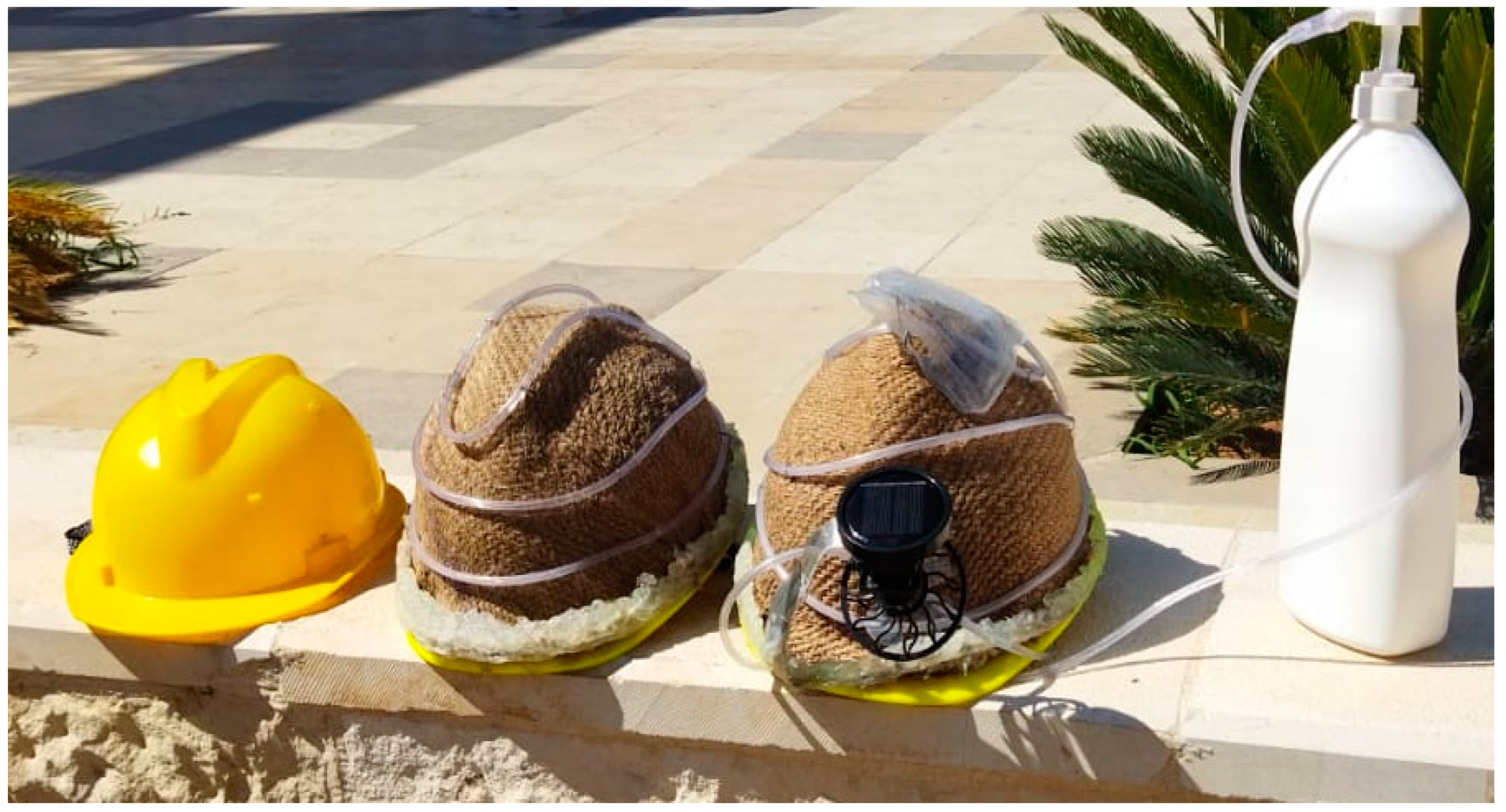
2.1. Working Principles and Operating Procedure

It is known that for water atoms to evaporate, they must gain energy that enables them to escape from a wet surface that covers the helmet and overcome the pressure of water vapor in the air. This energy is mostly sensible heat transferred to the water, which acquires it in the form of latent heat. The high temperature of the water, the low relative humidity of the air, and the rapid movement of wind increases the rate of evaporation. So, evaporation can occur even if the water temperature is not very high. When evaporation takes place, the water subtracts the required latent heat from the surface which leads to the cooling of the surface. This leads to the generation of a driving force that transfers heat from the user’s head to the inner surface of the helmet and then to its outer surface. Two other mechanisms occur between the outer surface and the surroundings, convection and radiation, with a heat flow direction depending on the temperature differences between the helmet surface, the ambient area, and the surrounding surfaces.
A schematic of the system is shown in Figure 1. It consists of the following parts:
  • A water supply bottle which holds water used to moisten the helmet cover and is equipped with a hand pump that allows pushing the water towards the reservoir at the top of the helmet.
  • A flexible plastic tube where part of it is used to deliver water from the bottle to the water reservoir on top of the cover and the other part is perforated to allow distribution of the water in such a way that the cover is uniformly moistened.
  • A small water tank on top of the helmet holds water that will be distributed over the helmet cover.
  • The helmet cover is the main part that provides a large surface area for the evaporation process and is made of canvas with a high absorption capacity to hold the water used in the evaporation process.
  • A small solar fan powered by solar energy to increase the wind speed intended to enhance the evaporation rate from the cover surface. This fan receives its energy from the solar panel and delivers air at a speed of around 2.3 m/s.
To demonstrate the advantages of the proposed system, a comparison was made with two other systems, as shown in Figure 2. In the first system, a dry helmet is considered where the heat transfer around the outer surface occurs through radiation and convection. The direction of flow depends on the temperature difference between the helmet surface, the ambient air, and the surrounding surfaces. In the second system, a wet helmet is considered where all components are assembled except the fan. In this system, the evaporative cooling effect is involved. In the proposed system under consideration, the wet helmet is ventilated by the solar fan to enhance convection and evaporative effects.
The cover is moistened by delivering water from the bottle to the reservoir fixed on top of the cover and then to the flexible tube that wraps around the helmet and is perforated to allow water to seep through the holes to wet the cover. The water is pushed out of the plastic bottle by hand pressure on the piston of the manual pump which has a non-return valve to force the water to flow through the flexible plastic tube to reach the reservoir on top of the cover. The user has to repeat this process from time to time to ensure that the cover is kept wet.

2.2. Experimental Setup and Measuring Devices

The three systems were tested by recording the results every 10 min, and the test was carried out over a period of four days. During the test, a set of measuring devices were used to measure the various parameters. Table 1 lists the measuring devices used and their specifications.

3. Mathematical Modeling

3.1. Heat Transfer Rates

The helmet loses or gains heat by conduction through the shell and by convection, radiation, and evaporation after leaving the outer surface. Methods of evaluating heat transfer rates by these mechanisms are presented below [19].

3.1.1. Heat Transfer Rate by Conduction

The rate of heat transfer by conduction through the helmet shell, made of high-density polyethylene, can be calculated by Fourier’s law:
Q ˙ c o n d = k H D P E A s ( T s , o u t T s , i n ) t h
where k H D P E is the thermal conductivity of high-density polyethylene (HDPE), W/m∙K; A s is the surface area of the helmet, m2; T s , o u t and T s , i n are the temperatures of outer and inner surfaces of the helmet, respectively, K or °C; and t h is the thickness of the helmet shell, m. When applying Equation (1), it is assumed that the temperatures of the inner and outer surfaces of the helmet are uniformly distributed. Assuming that the helmet has a hemispherical shape, its surface area is given by:
A s = π 2 D 2
where D is the diameter of the helmet, m.

3.1.2. Heat Transfer Rate by Convection

As a result of the air flowing around the helmet surface, a heat exchange will occur between the air and the helmet. The rate of heat that flows from the helmet to the air, or vice versa, can be calculated using Newton’s law of convection:
Q ˙ c o n v = h c o n v A s T s , o u t T
where h c o n v is the convective heat transfer coefficient, W/m2∙K, and T is the ambient temperature, K or °C. The convective heat transfer coefficient is given by:
h c o n v = k a i r D N u
where k a i r is the thermal conductivity of the air, W/m·K, and N u is the Nusselt number. Using Whitaker’s comprehensive correlation for the flow over a sphere, Nusselt number is given by [19]:
N u = 2 + 0.4 R e 1 / 2 + 0.06 R e 2 / 3 P r 0.4 μ μ s 1 / 4
where R e is the Reynolds number, P r is the Prandtl number of dry air at free stream temperature; μ and μ s are dynamic viscosities of air at ambient and surface temperatures, respectively, kg/m·s. The fluid properties, in this case, are evaluated at the free-stream temperature T, except for µs, which is evaluated at the surface temperature Ts. The correlation is valid for 3.5 ≤ Re ≤ 83104, 0.7 ≤ Pr ≤ 380, and 1.0 ≤ (µ/µs) ≤ 3.2. The Reynolds number of air can be calculated using the equation:
R e = V D ν
where V is the air velocity, m/s, and ν is the kinematic viscosity of dry air at free stream temperature, m2/s.

3.1.3. Heat Transfer Rate by Radiation

The rate of heat transfer by radiation can be calculated by the equation:
Q ˙ r a d = ε σ A s T s , o u t 4 T s u r r 4
where ε is the emissivity of the cover; σ is the Stefan–Boltzmann constant, W/m2K4; and T s u r r is the surrounding temperature, K.

3.1.4. Heat Transfer Rate by Evaporation

The flow of air around the wet cover will lead to the evaporation of water, causing a decrease in its temperature. The rate of heat lost by evaporation can be calculated by the following formula:
Q ˙ e v a p = m ˙ v h f g
where m ˙ v is the rate of evaporation, kg/s, and h f g is the latent heat of vaporization of water at its temperature, kJ/kg. The rate of evaporation from the wet surface can be calculated by the equation:
m ˙ v = h m a s s A s ( ρ v , s ρ v , )
where h m a s s is the mass transfer coefficient, m/s; ρ v , s and ρ v , are the densities of the vapor at the wet surface and away from the wet surface, respectively, kg/m3. To facilitate the calculation, it can be assumed that water vapor is an ideal gas which is an acceptable assumption due to the low pressure of the vapor. Substituting the density value from the ideal gas equation into Equation (9) gives:
m ˙ v = h m a s s A s R v P v , s T s , o u t P v , T
where R v is the gas constant of the vapor, kJ/kg.K; P v , s and P v , are the pressures of the vapor at the wet surface and away from the wet surface, respectively, kPa. The air near the surface is saturated, and thus the vapor pressure P v , s is simply the saturation pressure of water at the outer surface temperature. The vapor pressure of air away from the surface P v , is determined by:
P v , = φ P s a t @ T
where φ is the relative humidity for the air and P s a t @ T is the saturation pressure of water vapor in the air at the ambient temperature, kPa. The mass transfer coefficient can be calculated using the following formula [19]:
h m a s s = S h D H 2 O - a i r D
where S h is Sherwood number, and D H 2 O - a i r is the mass diffusivity of the water vapor in the air, m2/s. The mass diffusivity of the water vapor in the air can be determined by:
D H 2 O - a i r = 1.87 × 10 10 T a v g 2.072 P a t m
where P a t m is the atmospheric pressure and T a v g is the average temperature between the surface and free stream temperature, K. The average temperature can be determined by:
T a v g = T + T s , o u t 2
Sherwood number for forced convection over a spherical surface is given by:
S h = 2 + 0.4 R e 1 / 2 + 0.06 R e 2 / 3 S c 0.4 μ μ s 1 / 4
where S c is Schmidt number which is given by:
S c = ν D H 2 O - a i r
The total heat flow rate (whether lost or gained by the helmet) is equal to the sum of the heat transfer by the three mechanisms, convection, radiation, and evaporation:
Q ˙ t o t = Q ˙ c o n v + Q ˙ r a d + Q ˙ e v a p
The total heat transfer can be estimated also by estimation of the conduction heat transfer as the same heat flow passing through the solid shell of the helmet is distributed among the three mechanisms after it comes out from the outer surface.
Q ˙ t o t = Q ˙ c o n d

3.2. The Amount of Water Required during the Operating Period

By knowing the rate of evaporation, it is possible to determine the mass of water that is required to evaporate to achieve cooling over a specified period of time t by the equation
m w = m ˙ v t
Based on that, the volume of water, which is equal to the required volume of the bottle can be determined by:
V = m w ρ w
where ρ w is the density of the water, kg/m3.

4. Results and Discussion

Many parameters such as solar intensity, ambient temperature, relative humidity, wind speed, and inner and outer surface temperatures were recorded over a period of four days. The measured values have been used with the laws of heat and mass transfer to calculate the rates of heat transfer and evaporation in the different cases studied. The helmet used has a shell thickness of 1 cm and a diameter of 20.7 cm with a hemispherical shape. It is made of high-density polyethylene (HDPE) which has a thermal conductivity of 0.44 W/m.K [20] and an emissivity of 0.3 [21]. The values recorded on one of these days were considered and analyzed to evaluate the results that illustrate the features of the proposed system.

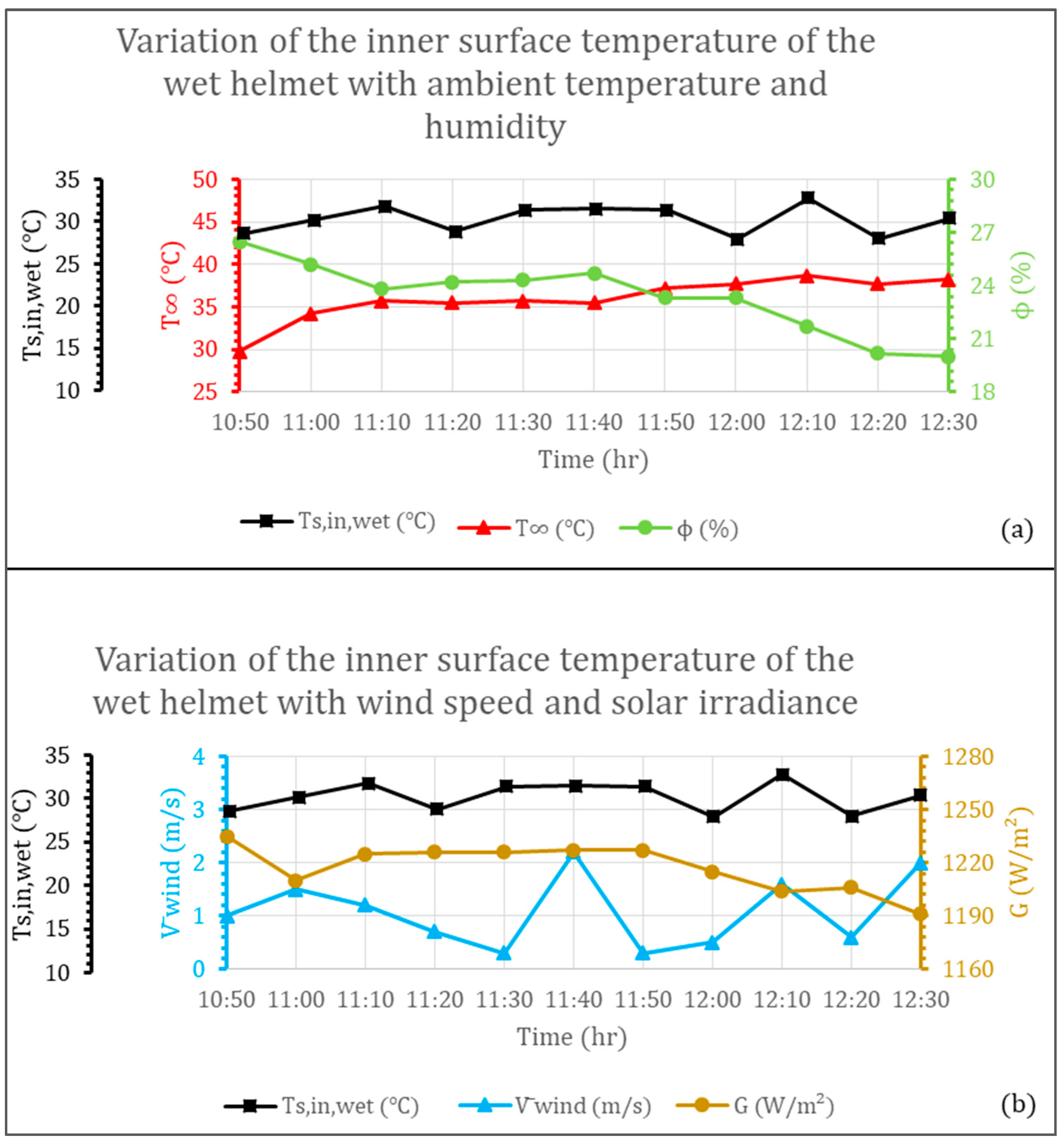
4.1. Variations of the Temperature of the Inner Surface of the Helmet with Various Parameters

The variations of the inner surface temperature with the various parameters, ambient temperature, wind speed, relative humidity, and solar intensity are shown in Figure 3, Figure 4 and Figure 5. In the case of the dry helmet system, shown in Figure 3, the inner temperature ranges between 35.3 and 43.9 with an average of 39 °C. In the case of the wet helmet system, shown in Figure 4, the inner temperature ranges between 27.9 and 32.8 with an average of 30.3 °C. This means that there was a drop of about 9 degrees in the temperature due to the addition of the wet cover. Considering the case in which the solar fan is added, shown in Figure 5, it can be noticed that the temperature of the inner surface ranges between 23.5 and 28 with an average that dropped to reach 25.2 °C. This means a drop of about 14 degrees with respect to the dry helmet case. This is an important result because this range of temperatures is compatible with the range that suits human comfort.
Another important result that can be observed from the three figures mentioned is the stability of the inner surface temperature in the wet and ventilated wet helmet cases. In fact, the fluctuations do not exceed 5 degrees. This means that the different parameters established a balanced overall effect. This also indicates that the most influential factor in the temperature values is the evaporative cooling process.

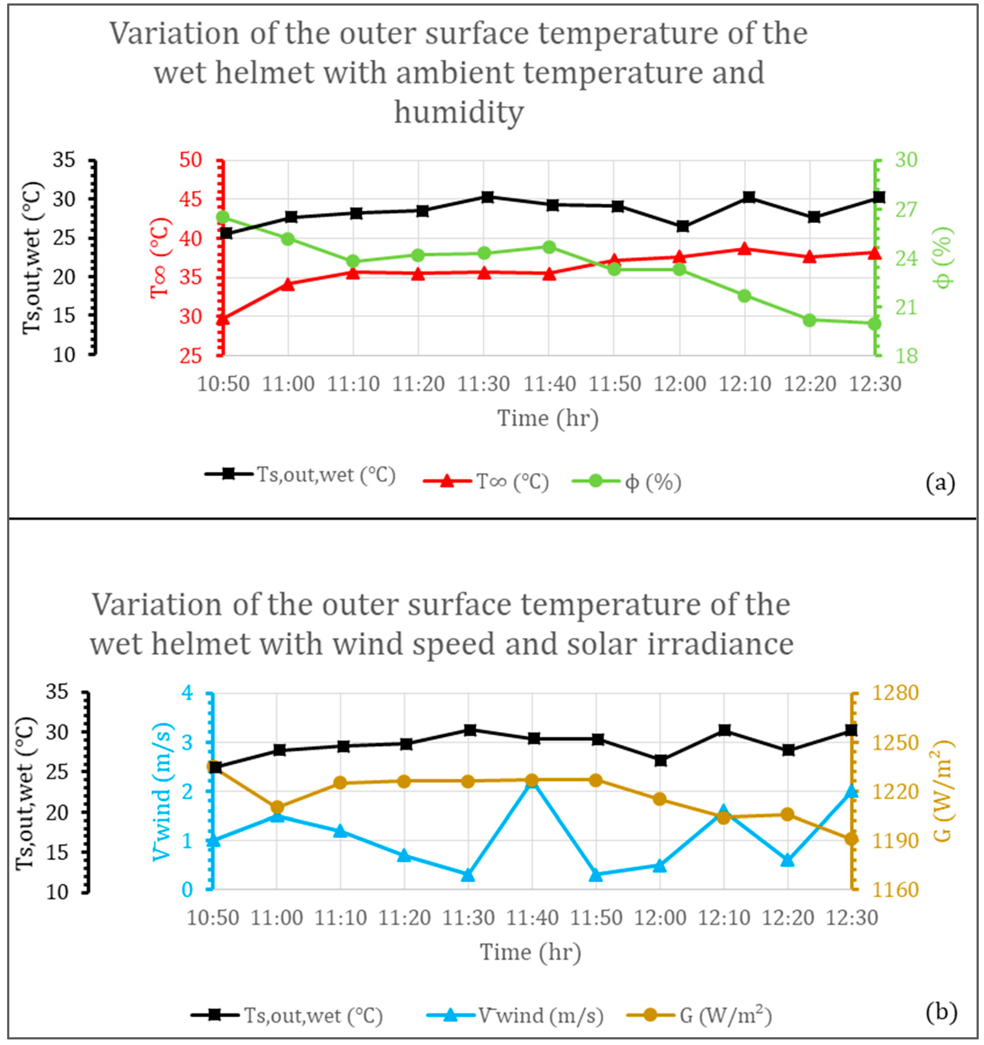
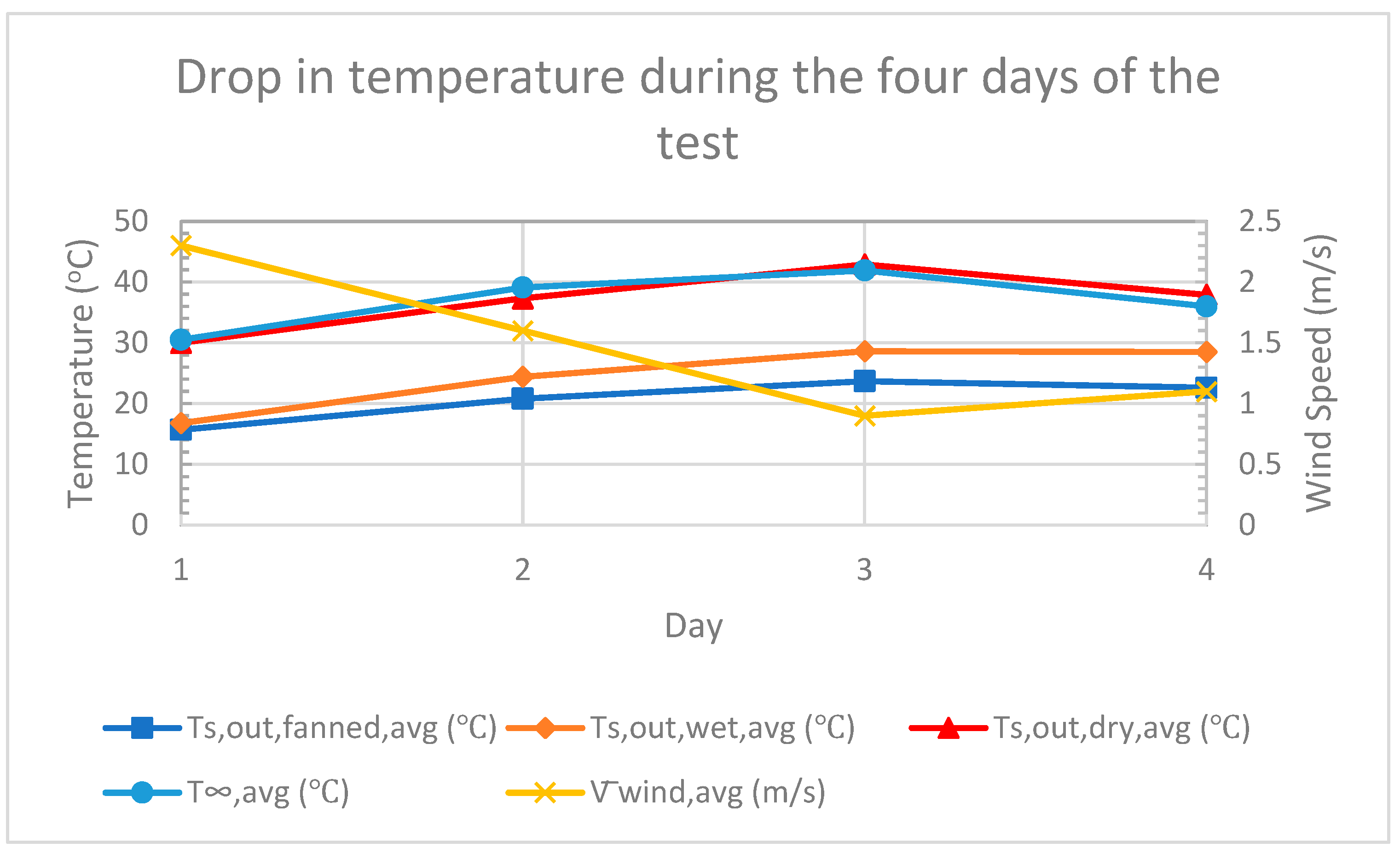
4.2. Variations of the Temperature of the Outer Surface of the Helmet with Various Parameters

The variations of the outer surface temperature with the various parameters, ambient temperature, wind speed, relative humidity, and solar intensity are shown in Figure 6, Figure 7 and Figure 8. It can be noticed that the average temperatures of the outer surface were 37.9, 28.5, and 22.7 °C in the cases of the dry helmet, wet helmet, and ventilated wet helmet, respectively. That is, the wet cover led to a decrease of about 9 degrees, and the use of the fan led to an additional decrease of about 6 degrees. Additionally, in this case, the stability of the outer surface temperature is noticed in both cases, the wet helmet and the ventilated wet helmet.

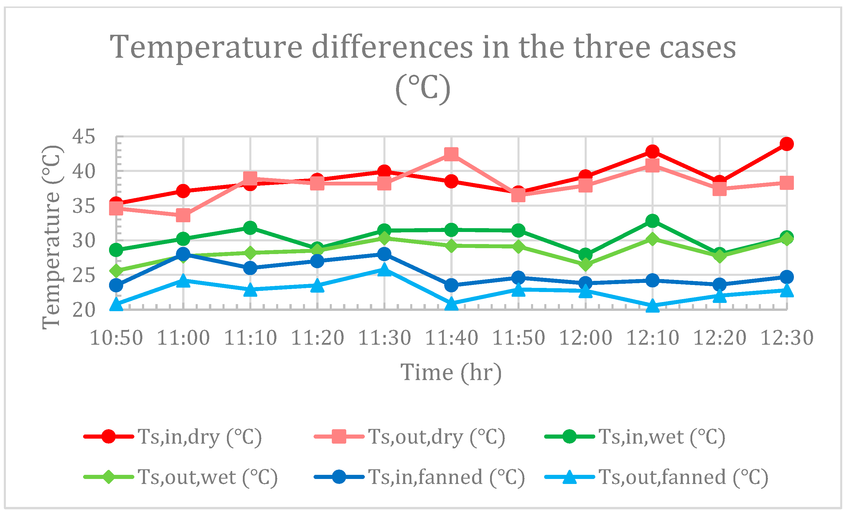
4.3. The Differences between the Outer and the Inner Surface Temperatures in the Three Cases

As can be noticed in Figure 9, the outer surface temperature is less than the inner surface temperature in the cases of wet helmet and ventilated wet helmet. This means that the heat flow is directed from the inside of the helmet to the outside. This therefore indicates that it helps to release the heat produced by the head. In the case of the dry helmet, it is noticed that the flow direction fluctuates between entering and exiting according to the changes in temperature differences between the inner and the outer surfaces.
The other thing that can be noticed is the differences between the average temperatures of the outer and inner surfaces, which was equivalent to 1.1 degrees in the case of a dry helmet, 1.8 degrees in the case of a wet helmet, and 2.6 degrees in the case of a ventilated wet helmet. Since these differences are the driving forces for heat transfer, this means that the rate of heat flow to the outside will increase in the case of a wet helmet and increase more in the case of a ventilated wet helmet.
To compare the results during the four test days, the drop in temperatures in the cases of the wet cover and the ventilated wet cover is shown in Figure 10. This drop in the case of the ventilated wet cover compared with the dry cover during the four days was equivalent to 14.3, 16.5, 19.2, and 15.3 degrees, respectively. The significant drop on the third day can be attributed to the significant rise in the ambient temperature on that day as it reached 41.9 °C, which contributed to a significant increase in the evaporation rate. It is also noticed that the drop in temperature on the first day in the case of the ventilated wet helmet is very close to that in the case of the wet helmet without the fan. This can be explained if it is noticed that the average wind speed without the fan was very close to the wind speed caused by the presence of the fan, which is equivalent to 3.2 m/s.

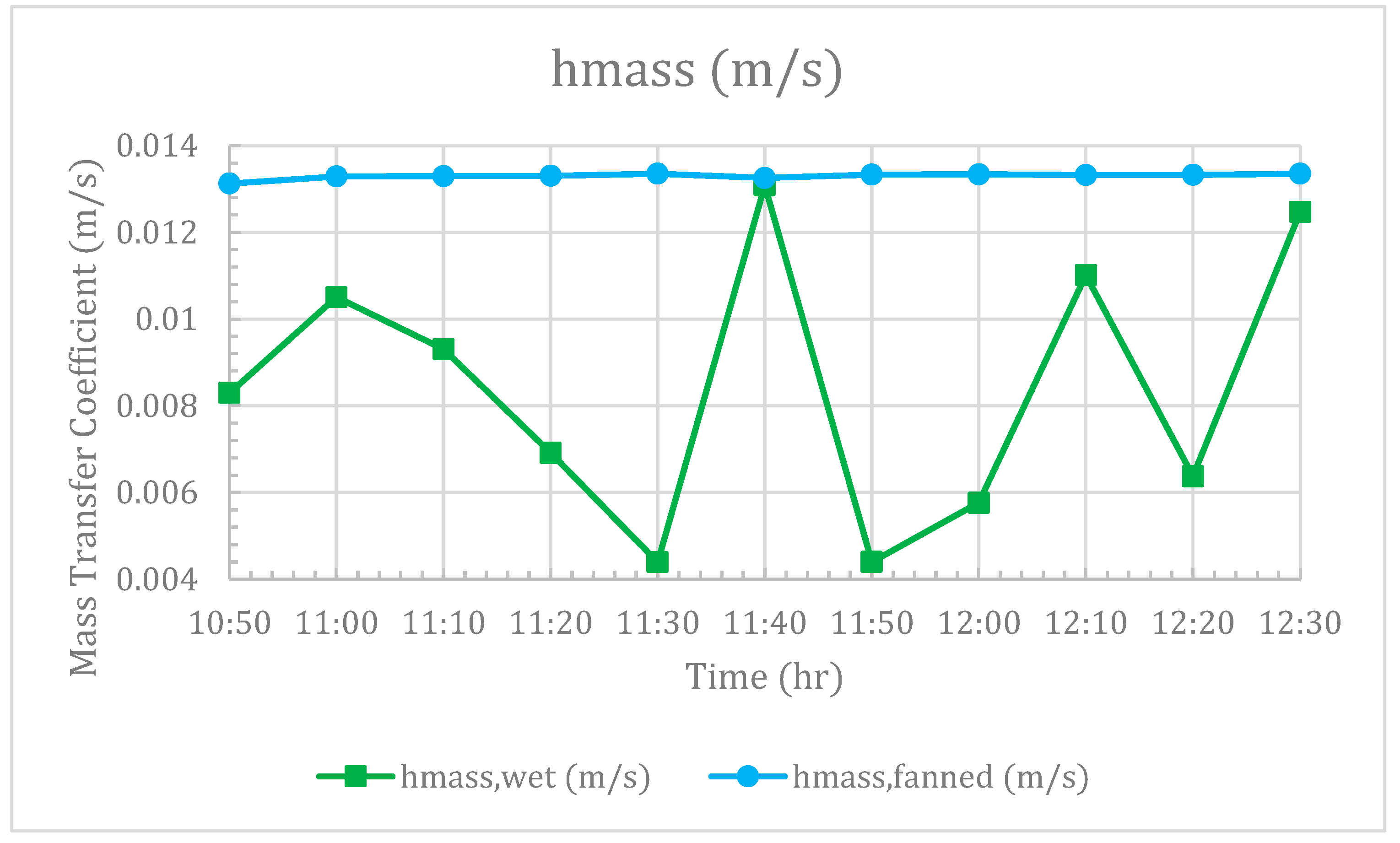
4.4. The Effect of the Fan Addition on the Mass Transfer Coefficient and Evaporation Rate

The effect of the fan presence on the mass transfer coefficient is shown in Figure 11. It can be noticed that there is a significant increase due to the presence of the fan. The average value without the presence of the fan is 0.0084, and that with the presence of the fan is 0.0133 m/s with an improvement of 58.1%. It can also be seen that there is stability in the values of the coefficient in the case of the fan presence while taking higher values, whereas there is a fluctuation in the values in the case of the wet helmet without the fan. The reason for this result is that the ventilated helmet was exposed to a constant-velocity wind generated by the fan with values greater than the variable wind velocity experienced by the wet helmet. Looking at the figure, it is noticed that the coefficient values in the two cases are very close to each other at 11:40 pm. Looking at the speed values, it can be noticed that there is a great convergence between the air speed without a fan, which is equal to 2.2 m/s, and that with the fan, which is equal to 2.3 m/s. This shows that wind speed is the main factor affecting the mass transfer coefficient.
This effect reflects positively on the evaporation rate from the wet cover and the ventilated wet cover as shown in Figure 12. This effect is represented in the relative stability of the evaporation rate in the case of the presence of the fan as a result of the stability of the wind speed generated by it. It can be noticed that the average values in the two cases are almost identical, 0.01 g/s in the case of the wet helmet and 0.0095 g/s in the case of the ventilated wet helmet. The fact that the evaporation rate is lower than expected in the presence of the fan can be explained by the fact that the temperature of the wet surface in this case is lower than in the absence of a fan, which contributes to reducing the evaporation rate. The average value of the evaporation rate can be used for sizing the supply bottle by multiplying the average evaporation rate by the required operating period.
These values of evaporation rates were calculated under ideal conditions in which maximum efficiencies of the system components were assumed. This was assumed in the pumping process, transporting water through pipes, distribution, and evaporation, which is contrary to reality, as there are sources of losses in all these processes. Accordingly, it can be said that the real amount of water required will be greater than the calculated values. This will be a motive for future work represented in developing a more efficient water distribution system that can be automatically controlled and powered by solar energy.

4.5. The Variation in the Total Heat Transfer Rates with Respect to Time in the Three Cases

The total heat transfer in the three cases considered can be evaluated by evaluating the heat transfer by conduction through the helmet shell. The reason for this is that the heat flow itself turns into other mechanisms such as convection, radiation, and evaporation after leaving the outer surface. The conduction heat transfer in the three cases can be evaluated based on the temperatures of the inner and outer surfaces recorded experimentally. As expected, the ventilated wet helmet has the highest value with an average value of 7.485 W, followed by the wet helmet with an average value of 5.277 W, followed by the dry helmet with an average value of 3.231 W. This means that there was an increase in the cooling rate equivalent to 63.3% when adding the wet cover, to increase to 131.7% when adding the fan with the wet cover. In addition to the advantage of increasing the cooling rate, there was another advantage that appears in Figure 13, which is the increase in the stability of the flow rate with the addition of the wet cover and the achievement of more stability with the addition of the fan.
Another thing that attracts attention is the presence of flow with a negative sign in the case of the dry helmet, which means flow in the opposite direction or heat gain. This is, in fact, expected, as the flow by convection and radiation reverses its direction if the ambient or surrounding surfaces temperatures are greater than the outer surface temperature of the helmet.

4.6. The Difference between the Rates of Heat Transfer by Different Mechanisms, Convection, Radiation, and Evaporation in the Case of the Ventilated Wet Helmet

The heat flow rates in the case of the ventilated wet helmet by the three mechanisms around the outer surface are illustrated in Figure 14. The average values for heat transfer by convection, radiation, and evaporation are −12.776 W, −1.692 W, and 23.222 W, respectively. This means that the rate of heat transfer by evaporation was higher than that by convection by 1.82 times and higher than that by radiation by 13.72 times. The negative sign means that the heat is flowing in the reverse direction or is a heat gain. This happens due to the lower temperature of the outer surface with respect to ambient and surrounding surfaces temperatures as mentioned before. This means that heat transfer by convection and radiation works inversely by heating the helmet instead of cooling it. These mechanisms contribute to cooling only when the outer surface temperature of the helmet exceeds both the ambient and the surrounding temperatures. Even if this is achieved, the contribution to the cooling process will be very small compared to the contribution of the evaporation process. This confirms that evaporative cooling is the decisive factor and therefore the proposed system provides an efficient solution to the problem of cooling helmets.

4.7. Spread of Data with Respect to the Central Values

To calculate the average of the absolute deviations of the data from the central point, the mean deviations are calculated for the sets of measured data as shown in Table 2. The low values that appear mean that the data points are clustered close to the mean.

4.8. Model Validation

The presented model is validated by comparison with an experimental model in which many experiments were conducted to study the cooling induced by fabric samples subjected to a controlled temperature, humidity, and airflow conditions [22]. One of the objectives was to study the evaporative cooling of a single-layer “fabric” sample for saturated (high water content) and moist (low water content) conditions.
The model considered for validation is similar to the proposed model in many aspects. It presented a test protocol to measure evaporative cooling that is not affected by metabolic heat loss or sweating, and the wet samples were placed onto a convex surface made of Styrofoam which did not absorb water. In addition, the water used to moisten the samples was kept at a temperature similar to the ambient air temperature. The tests were carried out under specified conditions of an air velocity of 1.5 m/s, an air temperature of 22 °C (±2 °C), and a relative humidity of 15% (±5%). As shown in Table 3, it has been observed that the temperature drop reached a stable value after 5 min for both samples, moist and saturated. The decrease in temperature was equivalent to 8.5 °C for the moist sample and 8.8 °C for the saturated sample.
The results reached in this study are shown in Table 4. These results were recorded after reaching steady flow conditions. By comparison between the two models, it can be noticed a good agreement as the deviation between the two values does not exceed 0.9 degree in the case of the moist sample and 0.6 degree in the case of the saturated sample. The differences can be attributed to some fluctuations in the conditions associated with the tests conducted in this study.

5. Conclusions

In this study, a novel experimental model was proposed, built, and tested to provide an efficient model to solve the problem of cooling helmets. The model suggests covering the helmet with a canvas that is wetted with a simple manual system. A solar fan was installed to enhance the evaporation rate.
The proposed system was analyzed under some reasonable assumptions such as assuming that the helmet has a hemispherical shape with uniform external and internal surface temperatures which means a one-dimensional heat flow in the radial direction. It was also assumed that air and water vapor are ideal gases. Some limitations were encountered in this study. The main limitation is the lack of previous studies dealing with similar systems that might allow for a comprehensive comparison. There were other limitations due to financial constraints that discouraged the use of a sophisticated system for distributing water over the wet cover in an efficient manner. On the other hand, these limitations constituted an important opportunity to identify new gaps in the literature and highlight the need for further research.
From the work conducted, it can be concluded the following:
  • The proposed system is characterized by ease of implementation and free power consumption.
  • By covering the helmet with a wet canvas, both the temperatures of the outer and the inner surfaces dropped by about 9 degrees with respect to the dry uncovered helmet. The addition of the solar fan helped in a further drop of the temperatures of about 5 degrees.
  • Both the outer and the inner surface temperatures were characterized by a good level of stability with ranges of temperatures that are compatible with human comfort conditions.
  • In the cases of wet and ventilated wet helmets, the inner surface temperature is higher than the outer surface temperature, so the heat flow is directed from the inside to the outside and works to release the heat produced by the human head.
  • The addition of the fan led to increased stability in the values of the mass transfer coefficient and evaporation rate.
  • There was an increase in the cooling rate equivalent to 63.3% when adding the wet cover, and an increase of up to 131.7% when adding the fan with the wet cover.
  • In the case of the ventilated wet helmet the rate of heat transfer by evaporation was higher than that by convection by 1.82 times and higher than that by radiation by 13.72 times.
  • Heat transfer in the case of evaporation always goes outside to contribute to the cooling process, while heat transfer by convection and radiation fluctuates in and out according to the differences in temperature values.
  • The proposed system can be developed to include an automatic water distribution system to improve performance, and it can be driven by solar energy to maintain the advantage of being power free.

Author Contributions

Conceptualization, A.S.; Methodology, D.A.K.; Software, D.A.K.; Validation, A.S.; Formal analysis, D.A.K.; Investigation, A.S.; Resources, A.S.; Data curation, D.A.K.; Writing—original draft, D.A.K.; Writing—review & editing, A.S.; Visualization, A.S.; Supervision, A.S.; Project administration, A.S. All authors have read and agreed to the published version of the manuscript.

Funding

This research received no external funding.

Data Availability Statement

The authors confirm that the data supporting the findings of this study are available within the article.

Conflicts of Interest

The authors declare no conflict of interest.

Nomenclature

A Area, (m2)
D Diameter, (m)
D H 2 O - a i r Mass diffusivity of water vapor in the air, (m2/s)
h Heat transfer coefficient, (W/m2·K)
h f g Latent heat of vaporization, (kJ/kg)
h m a s s Mass transfer coefficient, (m/s)
k Thermal conductivity, (W/m·K)
m ˙ v Evaporation rate, (kg/s)
m Mass, (kg)
N u Nusselt number
P r Prandtl number
P Pressures, (kPa)
Q ˙ Heat transfer rate, (W)
R e Reynolds number
R v Vapor gas constant, (kJ/kg·K)
S c Schmidt number
S h Sherwood number
t Time, (s)
T Temperature, (°C or K)
t h Helmet shell thickness
V Container volume, (mL)
V Air velocity, (m/s)
Subscripts
Ambient
a i r Air
a t m Atmospheric
a v g Average
c o n d Conduction
c o n v Convection
d a Dry air
e v a p Evaporation
H D P E High-density polyethylene
h e a t Heat
i n Inner surface
o u t Outer surface
r a d Radiation
s Surface
s a t Saturation
s u r r Surroundings
t o t Total
v Vapor
w Water
Greek letters
ε Emissivity
μ Dynamic viscosity, (kg/m·s)
ν Kinematic viscosity, (m2/s)
ρ Density, (kg/m3)
σ Stefan–Boltzmann constant, (W/m2K4)
φ Relative humidity

References

  1. Van Hoof, J.; Mazej, M.; Hensen, J.L.M. Thermal comfort: Research and practice. Front. Biosci. Landmark 2010, 15, 765–788. [Google Scholar] [CrossRef] [PubMed]
  2. Kaushik, A.; Arif, M.; Tumula, P.; Ebohon, O.J. Effect of thermal comfort on occupant productivity in office buildings: Response surface analysis. Build. Environ. 2020, 180, 107021. [Google Scholar] [CrossRef]
  3. Davis, G.A.; Edmisten, E.D.; Thomas, R.E.; Rummer, R.B.; Pascoe, D.D. Effects of ventilated safety helmets in a hot environment. Int. J. Ind. Ergon. 2001, 27, 321–329. [Google Scholar] [CrossRef]
  4. Cao, Y.; Lei, T.H.; Wang, F.; Yang, B.; Mündel, T. Head, Face and Neck Cooling as Per-cooling (Cooling during Exercise) Modalities to Improve Exercise Performance in the Heat: A Narrative Review and Practical Applications. Sports Med. Open 2022, 8, 1–17. [Google Scholar] [CrossRef] [PubMed]
  5. Zambrano-Becerra, S.F.; Galvis-Sanchez, P.M.; Perez-Rangel, N.Y.; Florez-Solano, E.; Espinel-Blanco, E. Development of an integrated cooling system for motorcycle helmet by physical study of temperature variations and heat transfer. J. Phys. Conf. Ser. 2022, 2153, 012010. [Google Scholar] [CrossRef]
  6. Vijayrakesh, K.; Muthuvel, S.; Sivanamachivayam, G.; Yogeshwaran, N. Passive Cooling Application inside Helmet to Improve Ergonomics (21 December 2019). Available online: https://ssrn.com/abstract=3688975 (accessed on 10 March 2023).
  7. Mao, M.; Feng, C.; Pei, J.; Liu, H.; Jiang, H. A Triple-Layer Membrane with Hybrid Evaporation and Radiation for Building Cooling. Energies 2023, 16, 2750. [Google Scholar] [CrossRef]
  8. Lv, J.; Zhou, B.; Zhu, M.; Xi, W.; Hu, E. Experimental Study on the Performance of a Dew-Point Evaporative Cooling System with a Nanoporous Membrane. Energies 2022, 15, 2592. [Google Scholar] [CrossRef]
  9. Zhao, X.; Zhang, H.; Xi, X.; Liu, F.; Zhang, B. Effect of unidirectional surface roughness on heat transfer performance of spray cooling. Exp. Heat Transf. 2023, 36, 96–119. [Google Scholar] [CrossRef]
  10. Aamir, M.; Qiang, L.; Xun, Z.; Wang, H.; Ullah, R. Study on Ultra-fast Cooling Behaviors of Water Spray Cooled Stainless Steel Plates. Exp. Heat Transf. 2016, 29, 299–321. [Google Scholar] [CrossRef]
  11. Saleh, A.; Al-Nimr, M.A. Evaporative System for Water and Beverage Refrigeration in Hot Countries. J. Power Energy Part A 2007, 221, 1099–1105. [Google Scholar] [CrossRef]
  12. Saleh, A.; Al-Nimr, M.A. A Modified Air Jet Refrigeration System. Int. J. Heat Technol. 2006, 25, 23–27. [Google Scholar]
  13. Kashyap, S.; Sarkar, J.; Kumar, A. Proposal and month-wise performance evaluation of a novel dual-mode evaporative cooler. Heat Mass Transf. 2019, 55, 3523–3536. [Google Scholar] [CrossRef]
  14. Zhang, Y.; Zhang, L.; Meng, Q.; Feng, Y.; Chen, Y. A dynamic experimental study on the evaporative cooling performance of porous building materials. Heat Mass Transf. 2017, 53, 2651–2662. [Google Scholar] [CrossRef]
  15. Mott, D.R.; Khine, Y.Y.; Gary Tan, X.; Bagchi, A. Head Evaporative Cooling From Forced and Natural Convection for Two Helmet-Pad Configurations. In Proceedings of the ASME 2021 International Mechanical Engineering Congress and Exposition, Virtual, 1–5 November 2021. [Google Scholar] [CrossRef]
  16. Evaporative Cooling Technology Cooling Helmet Insert, for Mining & Construction. Available online: https://www.indiamart.com/proddetail/cooling-helmet-insert-15429542812.html (accessed on 10 March 2023).
  17. Techniche HyperKewl Evaporative Head Cooling under Safety Helmet. Available online: https://www.safety-workwear-shop.com/en/techniche-hyperkewl-evaporative-head-cooling-under.html (accessed on 10 March 2023).
  18. Hard Hat Evaporative Cooling Pads. Available online: https://www.mdsassociates.com/catalog/p-104596/pip-ez-cool-hard-hat-evaporative-cooling-pads (accessed on 10 March 2023).
  19. Cengel, Y.A.; Ghajar, A.J. Heat and Mass Transfer: Fundamentals and Applications, 5th ed.; McGraw-Hill Education: New York, NY, USA, 2015. [Google Scholar]
  20. Hu, M.; Yu, D.; Wei, J. Thermal conductivity determination of small polymer samples by differential scanning calorimetry. Polym. Test. 2007, 26, 333–337. [Google Scholar] [CrossRef]
  21. Okada, T.; Ishige, R.; Ando, S. Analysis of thermal radiation properties of polyimide and polymeric materials based on ATR-IR spectroscopy. J. Photopolym. Sci. Technol. 2016, 29, 251–254. [Google Scholar] [CrossRef]
  22. Reischl, U.; Pace, K.; Colby, C.; Goonitelleke, R. Cooling Dynamics of Wet Clothing. In Advances in Physical Ergonomics and Human Factors. Advances in Intelligent Systems and Computing; Goonetilleke, R., Karwowski, W., Eds.; Springer: Cham, The Netherlands, 2016; Volume 489. [Google Scholar] [CrossRef]
Figure 1. Schematic diagram of the proposed system.
Energies 16 04046 g001
Figure 2. The three systems studied: dry helmet, wet helmet, and proposed ventilated wet helmet.
Energies 16 04046 g002
Figure 3. Variations of the temperature of the inner surface of the helmet with various parameters in the case of the dry helmet.
Energies 16 04046 g003
Figure 4. Variations of the temperature of the inner surface of the helmet with various parameters in the case of the wet helmet.
Energies 16 04046 g004
Figure 5. Variations of the temperature of the inner surface of the helmet with various parameters in the case of the ventilated wet helmet.
Energies 16 04046 g005
Figure 6. Variations of the temperature of the outer surface of the helmet with various parameters in the case of the dry helmet.
Energies 16 04046 g006
Figure 7. Variations of the temperature of the outer surface of the helmet with various parameters in the case of the wet helmet.
Energies 16 04046 g007
Figure 8. Variations of the temperature of the outer surface of the helmet with various parameters in the case of the ventilated wet helmet.
Energies 16 04046 g008
Figure 9. The differences between the temperatures of the inner and outer surfaces in the three cases.
Energies 16 04046 g009
Figure 10. Drop in temperature during the four days of the test.
Energies 16 04046 g010
Figure 11. The effect of the fan presence on the mass transfer coefficient.
Energies 16 04046 g011
Figure 12. The effect of the fan presence on the evaporation rate.
Energies 16 04046 g012
Figure 13. The total heat transfer rates in the three cases.
Energies 16 04046 g013
Figure 14. The differences between the rates of heat transfer by convection, radiation, and evaporation in the case of the ventilated wet helmet.
Energies 16 04046 g014
Table 1. Measuring devices and their specifications.
DeviceParameterRangeResolutionAccuracy
MS6252B AnemometerAmbient Temperature−10~60 °C0.1 °C±1.5 °C
Wind Velocity0.80~30.00 m/s0.01 m/s±2.0%
Relative Humidity20~80%0.1%±3.0%
Infrared Thermometer DT-8220Outer Surface Temperature−50~220 °C0.1 °C±2%
Digital LCD Temperature ThermometerInner Surface Temperature−50–+70 °C0.1 °C±1 °C
Tm-207 solar power meterSolar Intensity0–1999 W/m21 W/m2±10 W/m2 or ±5% whichever is greater in sunlight
Table 2. Mean deviations of measured data.
ParameterAverageMean Deviation
T (°C)361.7
G (W/m2)1217.511.1
Vwind (m/s)1.10.6
Vfan (m/s)2.30
ϕ (%)23.41.5
Ts,in,fanned (°C)25.21.5
Ts,out,fanned (°C)22.61.2
Ts,in,wet (°C)30.31.4
Ts,out,wet (°C)28.51.2
Ts,in,dry (°C)391.8
Ts,out,dry (°C)37.91.7
Table 3. Observed evaporative cooling data for the two single-layer fabric samples (saturated and moist) subjected to air at a speed of 1.5 m/s.
Exposure Time (min)Cotton Sample (Moist) (°C)Cotton Sample (Saturated) (°C)
0.56.75.7
1.07.87.4
1.58.38.2
28.48.5
58.58.8
108.58.8
158.58.8
Table 4. Experimental results recorded during one day in this study.
Time (h)Temperature of the Dry Outer Surface (°C)Temperature of the Wet Outer Surface
(°C)
Temperature Drop
(°C)
10:5034.625.69
11:0033.627.75.9
11:1038.928.210.7
11:2038.228.59.7
11:3038.230.37.9
11:4042.429.213.2
11:5036.529.17.4
12:0037.926.511.4
12:1040.830.210.6
12:2037.427.79.7
12:3038.330.28.1
Average37.928.59.4
Disclaimer/Publisher’s Note: The statements, opinions and data contained in all publications are solely those of the individual author(s) and contributor(s) and not of MDPI and/or the editor(s). MDPI and/or the editor(s) disclaim responsibility for any injury to people or property resulting from any ideas, methods, instructions or products referred to in the content.

