Article

A Pre-Synchronization Method for Parallel VSGs of Distributed Microgrid Based on Control Mode Switching

1
School of International Education (BAODING), North China Electric Power University, No. 619 Yonghua Road, Baoding 071000, China
2
Key Laboratory of Distributed Energy Storage and Micro-Grid of Hebei Province, North China Electric Power University, No. 619 Yonghua Road, Baoding 071000, China
*
Author to whom correspondence should be addressed.
Energies 2023, 16(10), 4069; https://doi.org/10.3390/en16104069
Submission received: 15 March 2023 / Revised: 14 April 2023 / Accepted: 24 April 2023 / Published: 12 May 2023

Abstract

:
For the pre-synchronization method of the virtual synchronous generator (VSG), only the case of a single VSG pre-synchronization and grid connection has been studied and analyzed. If the phase synchronization of multiparallel VSGs in a decentralized microgrid is realized by controlling a VSG, power circulation exists in the pre-synchronization process. Firstly, the structure and control mode of the microgrid are introduced. For the decentralized structure, a control mode switching mechanism under distributed communication is designed, and a pre-synchronization method of parallel VSGs based on control mode switching is proposed. Secondly, a theoretical analysis of the active power circulation problem is performed by an equivalent frequency model for parallel VSGs in the pre-synchronization process. Finally, the simulation results show that the proposed pre-synchronization method can reduce the dynamic power circulation of parallel VSGs by 83%, and improve the pre-synchronization speed by 75%.

1. Introduction

A microgrid composed of distributed power sources can operate either in isolated island mode or grid-connected mode [1]. If precise pre-synchronization control of multiple inverters cannot be realized in the off-grid conversion process, power circulation and grid-connected impulse current will appear [2,3]. For multiple virtual synchronous generator [4] (virtual synchronous generator, VSG) synchronous control, under the action of a synchronous controller, all the VSGs will respond. When the frequency or voltage deviation index reaches the threshold, the operation of the cutting machine and cutting load will occur, and could even cause a frequency instability or collapse of the whole system, which has a significant impact on the safety, stability, and operation of the system [5,6].
The conventional microgrid is divided into a centralized structure and a distributed structure, according to communication and control methods [7]. For the centralized structure, the central controller generates instructions to coordinate and control each micro source. In this structure, the inverter can adopt either a master–slave pre-synchronization control mode or a peer-to-peer pre-synchronization control mode. The literature [8] studies the pre-synchronization control method of the master–slave control microgrid, and generates secondary regulation instructions through the central controller to increase the synchronization consistency between micro sources. Peer-to-peer pre-synchronization control is mostly based on the droop principle. The literature [9,10] proposes an inverter control method with self-synchronization characteristics, which can achieve smooth switching between parallel and off-grid. The pre-synchronization control method of the multidroop control inverter system has been studied in the literature [11,12], but the power circulation problem of a multi-inverter system in the pre-synchronization process has not been explained and analyzed.
The pre-synchronization scheme, based on a centralized microgrid, has high requirements for equipment and communication, poor system stability, and high cost. The distributed structure eliminates the central controller, avoids the centralized communication, and only retains the basic signal communication between adjacent micro sources. In this communication structure, peer-to-peer sagging control is mostly adopted. However, due to the lack of unified regulation of a microgrid central controller (MGCC), control instructions cannot be issued to all micro sources at the same time, and it is difficult to realize VSG multimachine synchronous regulation.
When master–slave pre-synchronization control is adopted, only one master control unit is used to realize pre-synchronization adjustment by taking advantage of the self-synchronization characteristic of the sagging control of the slave control unit. In this way, it is easy to produce a large voltage difference and circulation between micro sources when multiple machines are pre-synchronized [13]. In view of this, this paper proposes to adopt the multi-VSG fast pre-synchronization method based on control mode switching in a distributed structure; that is, the master–slave pre-synchronization control is used to replace the equality pre-synchronization control, and the dynamic power circulation of the multi-VSG parallel system can be reduced by switching the slave control unit from sagging control to PQ control. Finally, the voltage amplitude and phase of the multiple VSG system can be pre-synchronized through the control of one VSG.

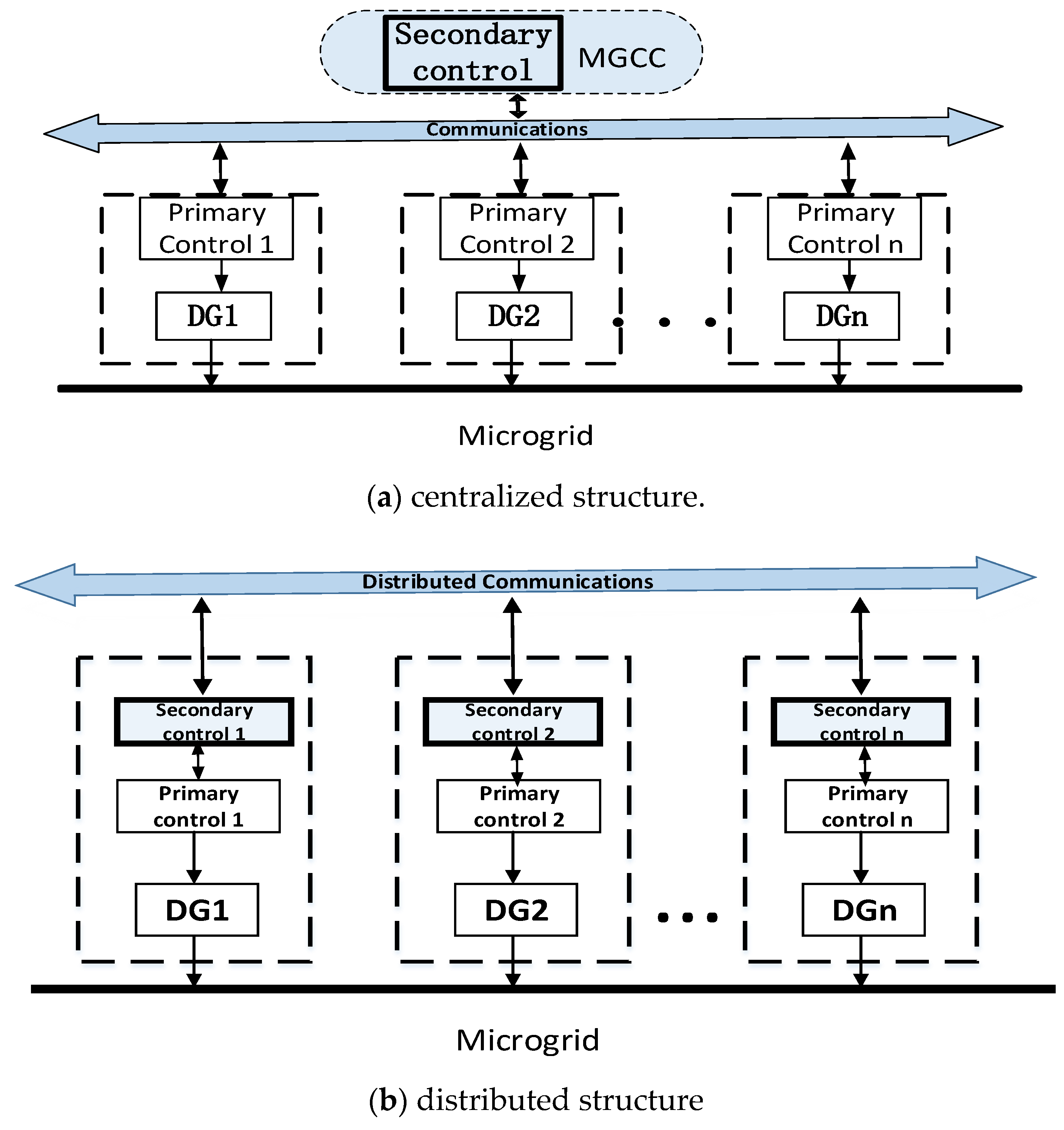
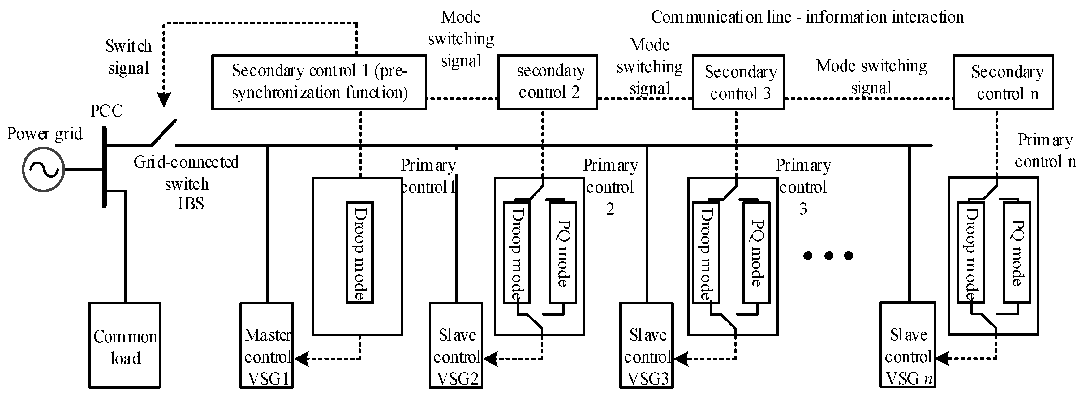
2. Microgrid Structure and Control Mode

When a VSG multimachine is in parallel operation, the unit coordination synchronization will affect the overall pre-synchronization performance. Reducing the voltage difference between units is the key to achieving a smooth transition of multimachine on-grid switchover. Thus, it is necessary to investigate the microgrid structure and VSG control mode, which are the determinants of voltage differences.

2.1. Microgrid Structure

The traditional microgrid can be divided into two structures according to communication types: centralized and distributed [7]. See Figure 1a,b, respectively.
The centralized control scheme: the control policy is implemented in MGCC. Each generating unit is controlled by its own master controller, and information sent to the MGCC is collected by a remote induction module. These measurements are then compared with references in the MGCC to generate commands for the master controller [14]. This structure can guarantee the performance of global optimization, but requires a complex topology, and may suffer from the disadvantages of a single point of failure that affects the performance.
The distributed control scheme: compared with centralized control, the distributed control scheme, with a small number of communication networks, has received increasing attention in recent years. The distributed controller only exchanges information with its directly adjacent controller, thus eliminating the need for monitoring MGCC, which means that the system is more flexible and reliable. The control principle of distributed communication is that the controller exchanges electrical quantity information with adjacent nodes, iteratively evaluates the average value of controlled parameters through a local distributed consistency algorithm, dynamically approaches the target value of parameters through local adjustment, and finally eliminates the differences between distributed power sources; the system tends to be consistent as a whole [15].
Based on the above two structures, the hierarchical control theory of the microgrid is developed. According to the hierarchical control theory, a microgrid system is divided into a primary regulator layer, a secondary regulator layer, and a tertiary regulator layer. Among them, the primary regulation layer usually adopts a linear sagging control strategy; that is, each distributed generator distributes load according to capacity. Although this control strategy can give the system good dynamic characteristics, it can only achieve differential regulation of the system frequency and voltage. In order to realize the nondifferential regulation of the frequency and voltage of the microgrid, secondary control must be introduced in the secondary regulation layer [16,17]. The tertiary regulation generally considers the optimization of the output of each generator and the power exchange between the microgrid and the large grid, which can provide an economic and optimal operation mode for the microgrid.
The switching of parallel and off-grid operation modes of the microgrid is realized in the secondary control layer, so the control layer should have the function of multisynchronization, and coordinate the switching of DG control modes of the microgrid.
For centralized structures: in the process of off-grid switching, the central control system must detect the voltage difference, frequency difference, and phase difference between the microgrid and the large grid in real time, and issue a unified adjustment command. When all of them meet the closing conditions, the central control system will issue grid-connected commands to each micro source at the same time, start the closing signal, and switch the island control strategy to the grid-connected control strategy, so as to realize the grid-connected operation.
For the distributed structure, due to the lack of MGCC, it is impossible to achieve synchronous adjustment, so there is no corresponding multi-synchronization method. This paper proposes a multi-VSG fast pre-synchronization method based on control mode switching, which utilizes the weak communication characteristics of the distributed structure to increase the transmission of mode control signals, based on the transmission of system state information. However, the dynamic consistency algorithm, commonly used in distributed communication, is only applicable to the regulation and control of electrical quantities, such as voltages and currents. On the other hand, the transmission and control of the mode signals, with only “0” and “1” digital quantities, have limitations. Therefore, based on the distributed architecture, it is necessary to design a communication mechanism, suitable for the operation mode switching. The specific implementation principle is detailed in Section 2.2.

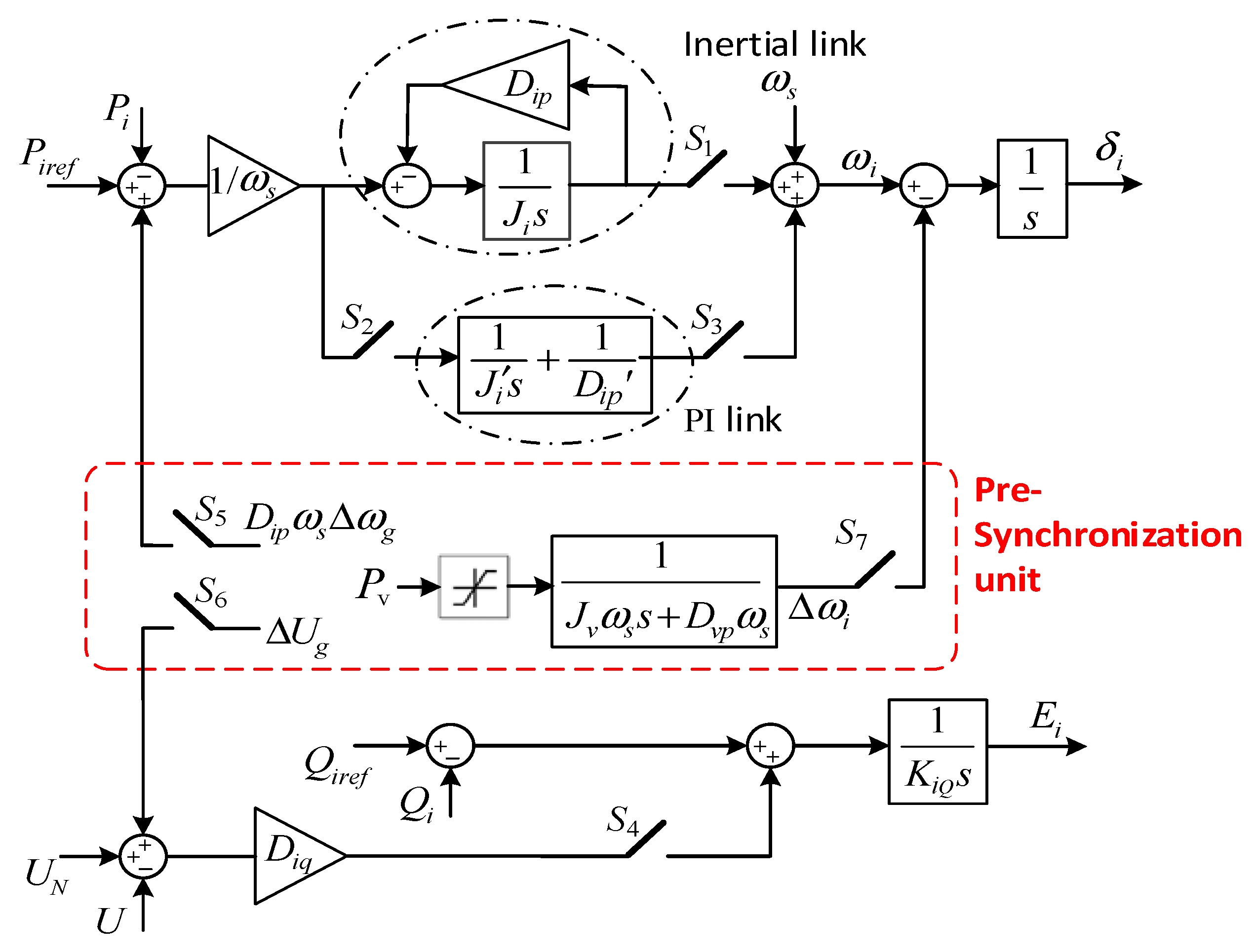
2.2. Control Mode of DG

Conventional PQ control is widely used due to its simplicity and power decoupling ability [18]. However, this paper applies a special PQ control structure [19] in order to facilitate smooth switching of control modes. Implementation of PQ control mode [19]: the inertial link in the VSG power loop is replaced by a PI link, and VSG can realize the errorless tracking of the given value of active power under the disturbance of grid frequency; then, the reactive power and the voltage regulation ring in the voltage regulation ring are disconnected, and VSG can realize the zero-error tracking of the given value of reactive power.
The specific power loop control block diagram is shown in Figure 2. Based on traditional VSG control, one PI loop and four switches are added. Dp and J in the figure are inertial link parameters. Dp′ and J′ in the figure are PI link parameters. When S1 and S4 are closed and S2 and S3 are disconnected, VSG works in droop mode; when S1 and S4 are disconnected and S2 and S3 are closed, VSG works in PQ mode. For PQ mode, the output of the PI link is a state quantity, and it needs to be initialized each time it is re-closed, so two switches S2 and S3 are set. To enable smooth switching of the control mode, Dp′ = Dp is selected. The steady-state performance of PQ mode is better than that of droop mode. However, the inertia and damping properties of PQ mode VSG are weaker than droop mode.

3. Pre-Synchronization Method Based on Control Mode Switching

In the operation of multiple VSGs with a distributed structure, there is a fast pre-synchronization mode: one VSG is used for pre-synchronization control (such as VSG1). This scheme is simple to control and fast to adjust, but its disadvantage is that active power circulation exists in the pre-synchronization process [13].
In this paper, VSG control is adopted for all micro sources in a distributed microgrid; VSG power loop control is shown in block Figure 2. In view of the disadvantages of peer-to-peer control in a distributed structure, the process of master–slave control multimachine pre-synchronization is realized by smooth switching of two control modes, on the basis of avoiding central scheduling. The principle is that the main control unit adopts droop mode to switch from the control unit to PQ mode. The phase pre-synchronization control is carried out only by the main control unit. The VSG self-synchronization feature in PQ mode ensures that the phase of the slave control unit is automatically synchronized with that of the main control unit, so that the voltage of the slave control unit can track the main control unit in real time, thus reducing the circulation and realizing the smooth switching of off-grid connection. Therefore, only the pre-synchronization control link [13] of the main control unit (red area in Figure 2) needs to be enabled; that is, switches S5~S7 are closed. The purpose is to achieve voltage amplitude, frequency, and phase regulation.

3.1. Switching Mechanism of Control Modes

Due to the lack of MGCC sending instructions to the controller vertically, it is necessary to realize free switching of the control mode through horizontal communication between micro sources. However, the complex topological connection structure between micro sources, the bidirectional nature of communication, and the equality of signals make it difficult to transmit the control mode signals of the master control unit to all slave control units. Based on this, this paper designs a control mode switching mechanism under distributed communication. The principle is as follows.
In a communication cycle, each slave control unit completes three steps in sequence: ① receive mode signals transmitted by adjacent units; ② mode switching according to the set algorithm; ③ the mode signal of this unit is transmitted to adjacent units.
There are only two mode signals in Step ①: “0” represents “droop mode” and “1” represents “PQ mode”.
The principle of the algorithm in Step ② is to perform the “OR operation” or “AND operation” on the received mode signal and local mode signal. In particular, the calculation result of “OR operations” for multiple “1” is still “1”. The specific calculation rules are as follows: if the received mode signal and local signal are both “0”, the operation is set to “OR”; if the received mode signal and local signal are both “1”, the operation is set to “AND”; in other cases, the original operation settings remain unchanged.
For Step ③, the local primary controller switches the control mode according to the calculation result, and transmits the mode signal to the neighboring unit.
The main control unit sends mode control signals and completes mode switching after M communication cycles. M is affected by the number of slave control units and the topology of communication connections between micro sources. It is assumed that there are N slave control units in the microgrid. In numerous topologies, when N units are connected in pairs to form a chain structure, the mode switching takes the longest time, and at this time, M = N + 2. Therefore, after M communication cycles, it can be determined that the mode switchover is complete, regardless of the connection relationship.
This paper selects a typical distributed topology structure to verify the correctness of the method. As shown in Figure 3, there is one master control unit and five slave control units. The connecting lines between units represent the communication function between units, and mode instructions are issued by the master unit. Assume that all micro sources work in droop mode at the beginning, and the main control unit gives PQ mode switching instructions in the first communication cycle. The mode switching process is shown in Table 1. The main control signal represents the control signal sent by the main control unit. In the secondary control unit, the number represents the local control mode, “+” represents AND operation, and “X” represents OR operation.
At the fifth communication cycle, all control units switch from droop mode to PQ mode, and the operation changes from “OR” to “AND”; in the sixth time cycle, the main control unit sends the droop mode switching instruction. After four communication cycles, the mode switching is completed, and the operation changes from “AND” to “OR”, so as to prepare for the next mode switching.

3.2. Multi-VSG Pre-Synchronization Steps

Communication structures for parallel VSGs of distributed microgrid are shown in Figure 4. Steps of multi-VSG pre-synchronization based on control mode switching are:
(1) In island mode, all VSGs operate in parallel in droop mode; one VSG is selected as the master control unit (the master control unit should have a close electrical distance from the junction point and a large capacity), and the remaining VSGs as the slave control units.
(2) When receiving the grid-connected instruction, the main control unit will maintain the droop mode and issue the instruction to switch the control from the control unit to the PQ mode.
(3) Determine whether pre-synchronization of the main control unit is enabled after the mode switchover of all slave control units is complete.
(4) After phase pre-synchronization completion, issue the closing instruction of grid-connected switch.
(5) After the grid-connected operation is stable, the pre-synchronization of the main control unit is disabled, and the secondary control unit switches from PQ mode back to droop mode.
The whole process does not require central scheduling, but only requires the transmission of pre-synchronization start and end mode signals between adjacent micro sources, which has very low communication requirements, simple steps, and high reliability.

4. Model Analysis of Pre-Synchronization Control for Multi-VSG Parallel System

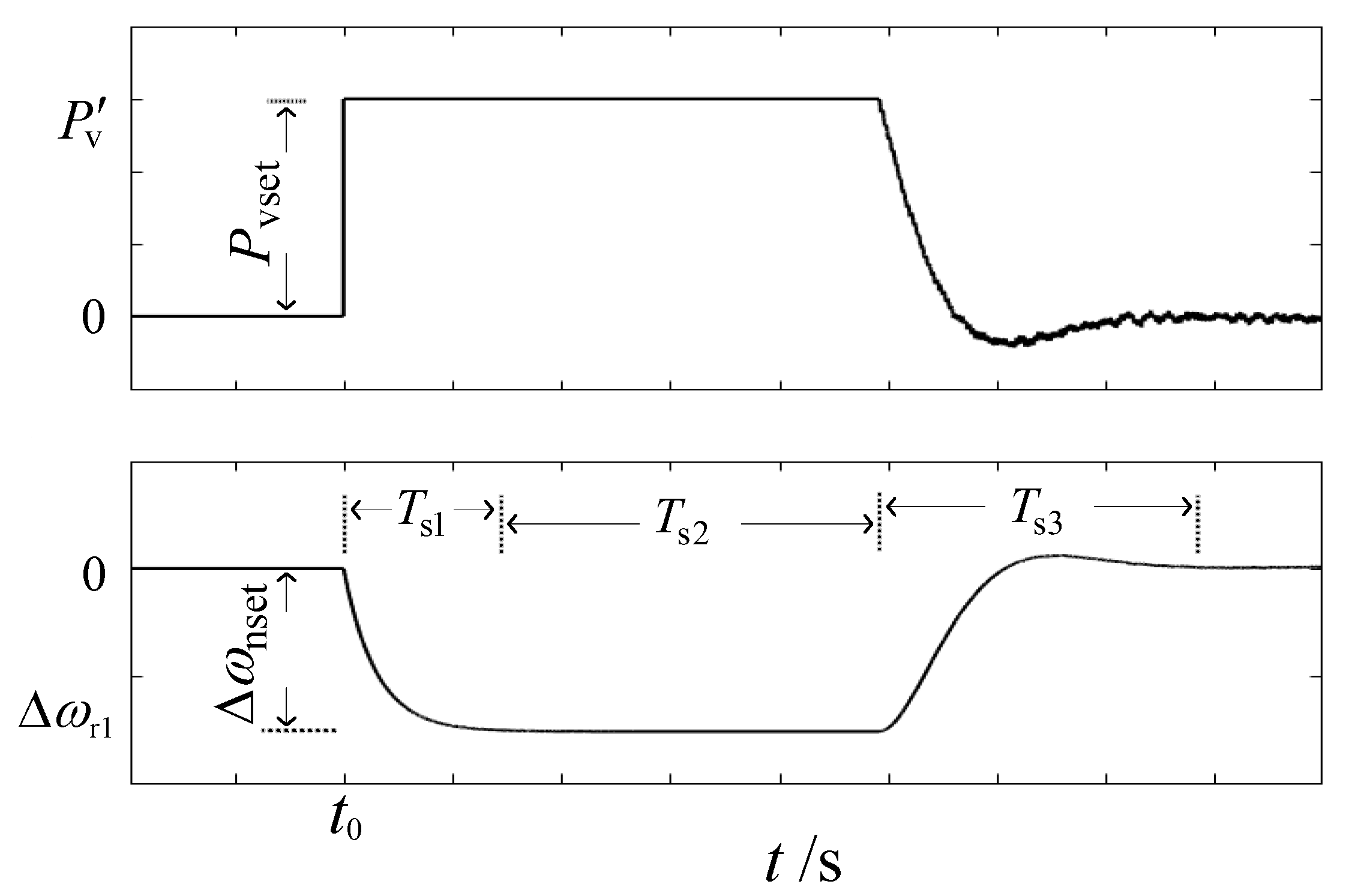
4.1. Decomposition of Phase Pre-Synchronization Process

In Figure 2, the pre-synchronization unit has the function of regulating voltage amplitude, frequency, and phase. ΔUg refers to the grid voltage deviation value. DipωsΔωg refers to the variable of frequency deviation feedback. Pv refers to the virtual power [13]. The feedback of ΔUg, DipωsΔωg, and Pv are used to regulate voltage amplitude, frequency, and phase, respectively. The pre-synchronization unit is enabled when S5, S6, and S7 are closed. The control loop 1/(Jvωs + Dvpωs), with input limiting, is adopted in the phase pre-synchronization controller, because the research in the literature [13] shows that the control effect of this loop is better. In order to keep the VSG output frequency within the limit during pre-synchronization, the output limit of the limiting link is ± Pvset. When PvPvset, the multi-VSG system performs an open-loop phase adjustment; when Pv < Pvset, the multi-VSG system performs a closed-loop phase adjustment.
Figure 5 is a schematic diagram of phase pre-synchronization process. t0 in the figure is the starting time, Δωnset is the set value of angular frequency deviation for multi-synchronization of VSG, Pvset = DvpωsΔωnset, Pv′ is the output of Pv through the limiting link in Figure 2. The phase pre-synchronization process is divided into three periods: Ts1 and Ts2 are the dynamic and steady-state time of open-loop phase adjustment, respectively, and Ts3 is the dynamic time of closed-loop phase adjustment.

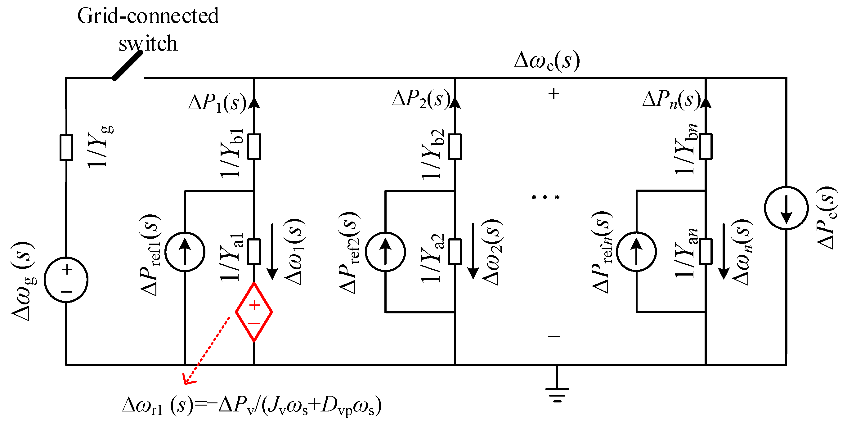
4.2. Modeling of Phase Pre-Synchronization Process

According to the modeling method in [20], the equivalent P-ω circuit model of the multi-VSG parallel system in Figure 6 was established to analyze the circulation problem in the pre-synchronization process of the multimachine parallel system, and this model was used as the guidance for parameter design.
VSG1 in the multiple VSG parallel system was selected for phase pre-synchronization control. Correspondingly, the disturbance source Δωr1 = −ΔPv/(Jvωs + Dvpωs) is added to the VSG1 branch of the P-ω model, as shown in Figure 6. When VSGi adopts droop control mode, the equivalent admittance parameters have been given in Equation (1a); when VSGi adopts PQ control mode, the equivalent admittance parameters are shown in Equation (1b). The response of the system under the disturbance of Δωr1(s) satisfies the following equation when the small disturbance is stable. The equation when VSG2~VSGn is in droop control mode is Equation (2a), and the equation when VSG2~VSGn is in PQ control mode is Equation (2b).
{ Y a i ( s ) = J i ω s s + D i p ω s Y b i ( s ) = K P i s
{ Y a i ( s ) = J i ω s D i p s J i s + D i p Y b i ( s ) = K P i s
{ Δ ω r 1 ( s ) = n Δ ω c ( s ) Δ P 1 ( s ) = k = 2 n Δ P k ( s ) Δ P 2 ( s ) = Δ P i ( s ) ( i = 2 , 3 , , n )
{ Δ ω r 1 ( s ) = Δ ω c ( s ) Δ P i ( s ) = 0 ( i = 1 , 2 , , n )
As can be seen from Equation (2), when the open-loop phase adjusts the steady-state (Ts2 period), Equation (3) is satisfied. When VSG2~VSGn is in droop control mode, the equation is Equation (3a); when VSG2~VSGn is in PQ control mode, the equation is Equation (3b).
{ Δ ω c = Δ ω n s e t / n P 1 = ( n 1 ) P i ( i = 2 , 3 , , n )
{ Δ ω c = Δ ω n s e t P i = 0 ( i = 1 , 2 , , n )
It can be seen from Equation (3) that in the period of Ts2, when VSG2~VSGn is in droop control mode, the frequency adjustment amount Δωc is inversely proportional to the number of VSGs in parallel and disturbs the voltage source; accordingly Δωr1 will generate circulation in each branch, and the circulation value of branch 1 is equal to the negative number of the total circulation of other branches. Frequency regulation when VSG2~VSGn is switched to PQ control mode Δωc is independent of the number of VSGs in parallel, and Δωc = Δωnset; accordingly, the multi-VSG system has the fastest pre-synchronization adjustment speed.
In order to analyze the dynamic response characteristics of active circulation in the Ts1 period and Ts3 period, it is necessary to derive the transfer function of circulation P1, and only analyze the response of the system under the action of Δωr1(s). First, the Δωc response to the transfer function under Δωr1 is Equation (4), where Ypi = YaiYbi/(Yai + Ybi).
Δ ω c Δ ω r 1 = Y p 1 Y p 1 + i = 2 n Y p i
Secondly, according to Figure 6, Δ P 1 = i = 2 n Δ P i = Δ ω c i = 2 n Y p i . According to the literature [13], the transfer function of the phase pre-synchronization control loop is Δωr1Pv = −1/(Jvωs + Dvpωs). Finally, the small signal model of pre-synchronization control of the multi-VSG parallel system can be obtained by combining Δφc = Δωc/s, as shown in Figure 7. Here, KPv = UUg/Zv, Zv is the virtual impedance used to calculate Pv, and Pv0 is the initial virtual power value.
According to Figure 7, the transfer function Equation (5) reflecting the response characteristics of circulation during the open-loop phase regulation (Ts1 period), and the transfer function Equation (6) reflecting the response characteristics of circulation during the closed-loop phase regulation (Ts3 period) can be obtained.
G r v ( s ) = Δ P 1 Δ P v 0 = Y p 1 i = 2 n Y p i ( J v ω s s + D v p ω s ) ( Y p 1 + i = 2 n Y p i )
Φ r v ( s ) = Δ P 1 Δ P v 0 = s Y p 1 i = 2 n Y p i ( J v ω s s 2 + D v p ω s s ) ( Y p 1 + i = 2 n Y p i ) + K P v Y p 1
The selection of the pre-synchronization controller needs to take into account the performance of Ts1 and Ts3 periods. Taking three VSG parallel systems as an example, and considering the same power loop parameters and output impedance of multiple VSG systems, the Bode diagram of circulation P1 under different control modes is drawn, as shown in Figure 8. Compare the response performance before and after the control mode switch. Jv = 0.3 kg·m2, Dvp = 20 N·m·s·rad−1. PI link parameters are set to 3.2 × 10⁻⁴ and 1.1 × 10⁻³, and other parameters can be found in the literature [13]. It can be seen that G r v ( s ) in droop mode has a constant gain in the low frequency band, indicating that the regulation in the Ts1 period will produce circulation. In PQ mode, G r v ( s ) and Φ r v ( s ) maintain attenuation characteristics in the low frequency band, and the attenuation rate is stronger than droop mode; at high frequencies, the two patterns are consistent. Therefore, the dynamic performance of pre-synchronization after control mode switching is better.

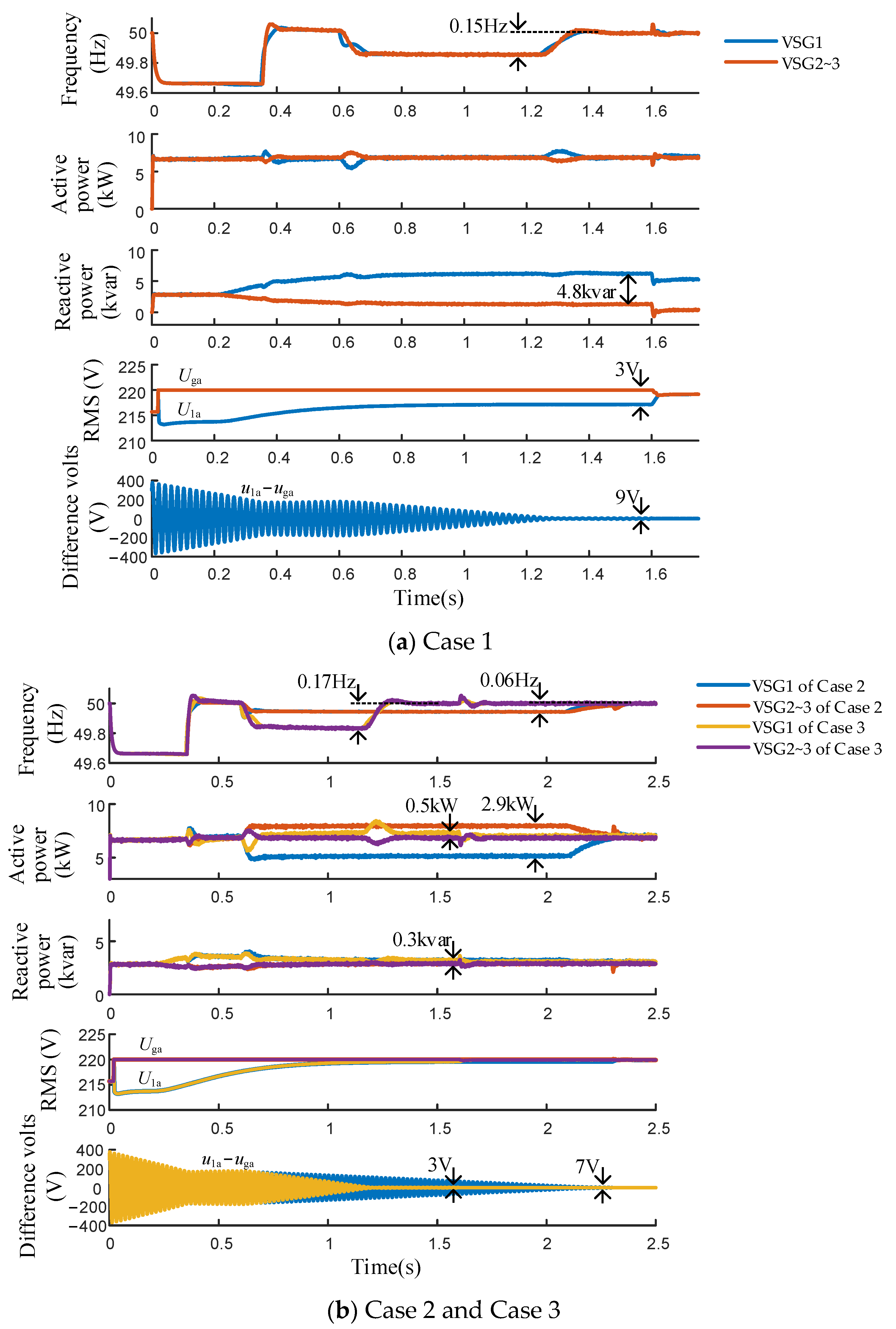
5. Simulation Verification

In order to verify the effectiveness of the proposed control strategy, three 10 kVA VSG parallel simulation models were built in MATLAB/SIMULINK. Set Pvset = 6 kW and Δf3set = 0.16 Hz. Three operating conditions with different control modes of VSG2~3 were simulated. Among them, S1 in case 1 is disconnected and S2~S4 is closed; S1 in case 2 is closed and S2~S4 is disconnected; S1 and S4 in case 3 are closed and S2 and S3 are disconnected. Case 2 is consistent with the literature [13], while case 3 corresponds to the proposed method. Simulation control: 0.2 s switch S6 closes and adjusts voltage; 0.35 s switch S5 closes for frequency modulation; 0.6 s switch S7 closes and starts phase pre-synchronization. Under cases 1 and 3, the grid-connected switch is closed at 1.6 s. Under case 2, the grid connection switch is closed at 2.3 s. When switching the control mode, the communication and control delay of 5 ms (between VSG1 and VSG2~3) is considered. The simulation results are shown in Figure 9.
Compare the simulation results of three working conditions, as shown in Table 2. Under reactive droop control, large reactive circulation appeared in condition 1, while under active droop control, large active circulation appeared in condition 2, and the power circulation in condition 3 was very small. In case 2, during the Ts2 period of phase pre-synchronization, the frequency deviation is 0.06 Hz = Δf3set/3, which is consistent with the analysis results of the small signal model.
As can be seen from the simulation results, the multimachine phase pre-synchronization process includes two processes: AC bus voltage and grid voltage synchronization process 1, and multimachine mutual synchronization process 2. Control requirements of process 1: the voltage frequency does not exceed the limit, to meet the power quality requirements. Control requirements of process 2: VSG power circulation is small. In case 3, the frequency and voltage are adjusted precisely while the circulation is kept small.

6. Conclusions

There is a power circulation problem in the process of pre-synchronization and grid connection of the multiple virtual synchronous generator system, which restricts and affects the speed and stability of multi-synchronization and grid connection of multi-VSGs. The small signal model analysis method is used to analyze the active circulation during the pre-synchronization process. In order to reduce dynamic power circulation, a distributed microgrid fast pre-synchronization scheme based on control mode switching is proposed. The regulating performance of the proposed method is compared and analyzed. The results show that the pre-synchronization control strategy, based on smooth switching of the control mode, can greatly reduce the active and reactive circulation in the process of frequency, amplitude, and phase adjustment, and can improve the speed of pre-synchronization. In comparison with the literature [13], the numerical improvement is that the maximum circulation is reduced to 17%, and the phase regulation speed is increased 1.75 times.

Author Contributions

Conceptualization, K.D. and J.J.; methodology, J.J.; software, K.D.; validation, K.D. and J.J.; formal analysis, J.J.; investigation resources, K.D.; data curation, K.D.; writing—original draft preparation, K.D.; writing—review and editing, K.D.; visualization, K.D.; supervision, J.J.; project administration, J.J.; funding acquisition, J.J. All authors have read and agreed to the published version of the manuscript.

Funding

This work was supported by the Science and Technology Project of Baoding, China (No. 2211ZG015); the Scientific Research Project of Colleges and Universities in Hebei Province, China (No. ZC2023047); and the Fundamental Research Funds for the Central Universities (No. 2022MS074).

Data Availability Statement

The authors will supply the relevant data in response to reasonable requests.

Conflicts of Interest

The authors declare no conflict of interest.

References

  1. Zhang, L.; Chen, K.; Cai, G. Research on the Operation Control Strategy of a Low-Voltage Direct Current Microgrid Based on a Disturbance Observer and Neural Network Adaptive Control Algorithm. Energies 2019, 12, 1162. [Google Scholar] [CrossRef]
  2. IEEE Standard 1547.4-2011; IEEE Guide for Design, Operation, and Integration of Distributed Resource Island Systems with Electric Power Systems. IEEE: Piscataway, NJ, USA, 2011; pp. 1–54.
  3. Shi, J.; Wu, D.; Qian, Y. A Novel Pre-Synchronization Control Method Based on Open-Loop Phase Detection for the Maritime VSC-HVDC System. Front. Energy Res. 2022, 10, 932971. [Google Scholar] [CrossRef]
  4. Liu, J.; Miura, Y.; Ise, T. Comparison of dynamic characteristics between virtual synchronous generator and droop control in inverter-based distributed generators. IEEE Trans. Power Electron. 2016, 31, 3600–3611. [Google Scholar] [CrossRef]
  5. Ashabani, M.; Freijedo, F.D.; Golestan, S.; Guerrero, J.M. Inducverters: PLL-Less Converters with Auto- Synchronization and Emulated Inertia Capability. IEEE Trans. Smart Grid 2016, 7, 1660–1674. [Google Scholar] [CrossRef]
  6. Meng, X.; Liu, J.; Liu, Z. A Generalized Droop Control for Grid-Supporting Inverter Based on Comparison between Traditional Droop Control and Virtual Synchronous Generator Control. IEEE Trans. Power Electron. 2019, 34, 5416–5438. [Google Scholar] [CrossRef]
  7. Gu, W.; Lou, G.; Tan, W. A nonlinear state estimator-based decentralized secondary voltage control scheme for autonomous microgrids. IEEE Trans. Power Syst. 2017, 32, 4794–4804. [Google Scholar] [CrossRef]
  8. Zheng, W.; Liu, L.; Zeng, J. Smooth Switching Strategy between Grid-Connected and Islanded Microgrid Using Improved Phase Control Method. Power Syst. Technol. 2016, 40, 1155–1162. [Google Scholar]
  9. Zhong, Q.; Nguyen, P.H.; Ma, Z. Self-synchronized synchronverters: Inverters without a dedicated synchronization unit. IEEE Trans. Power Electron. 2014, 29, 617–630. [Google Scholar] [CrossRef]
  10. Hariharan, R.; Mishra, M.K. Analysis and design of gradient descent based pre-synchronization control for synchronverter. IET Renew. Power Gener. 2021, 15, 297–312. [Google Scholar]
  11. Cheng, Q.; Chu, S.; Cheng, Y. Multiple Master-slave Mixed Coordinated Control for Microgrid Based on Improved Droop Control. Autom. Electr. Power Syst. 2016, 40, 69–75. [Google Scholar]
  12. Vasquez, J.C.; Guerrero, J.M.; Savaghebi, M. Modeling, Analysis, and Design of Stationary-Reference-Frame Droop-Controlled Parallel Three-Phase Voltage Source Inverters. IEEE Trans. Ind. Electron. 2013, 60, 1271–1280. [Google Scholar] [CrossRef]
  13. Wen, C.; Xiong, Q.; Jia, J. Research on multi-VSG fast pre-synchronization grid connection with dual power loop. Energy Rep. 2020, 6, 1226–1236. [Google Scholar] [CrossRef]
  14. Lou, G.; Gu, W.; Xu, Y.; Jin, W.; Du, X. Stability Robustness for Secondary Voltage Control in Autonomous Microgrids with Consideration of Communication Delays. IEEE Trans. Power Syst. 2018, 33, 4164–4178. [Google Scholar] [CrossRef]
  15. Shafiee, Q.; Guerrero, J.M.; Vasquez, J.C. Distributed secondary control for islanded microgrids—A novel approach. IEEE Trans. Power Electron. 2013, 29, 1018–1031. [Google Scholar] [CrossRef]
  16. Wu, T.; Liu, J.; Liu, Z. Load Power Estimation Based Secondary Control for Microgrids. In Proceedings of Ninth International Conference on Power Electronics-ECCE Asia, Seoul, Republic of Korea, 1–5 June 2015; pp. 722–727. [Google Scholar]
  17. Doost Mohammadi, F.; Keshtkar Vanashi, H.; Feliachi, A. State-Space Modeling, Analysis, and Distributed Secondary Frequency Control of Isolated Microgrids. IEEE Trans. Energy Convers. 2018, 33, 155–165. [Google Scholar] [CrossRef]
  18. Shao, B.; Xiao, Q.; Xiong, L.; Wang, L.; Yang, Y.; Chen, Z.; Frede, B.; Josep, M.G. Power coupling analysis and improved decoupling control for the VSC connected to a weak AC grid. Int. J. Electr. Power Energy Syst. 2023, 145, 108645. [Google Scholar] [CrossRef]
  19. Yan, X.; Jia, J.; Wang, D. Synchronous power control and mode smooth switching of virtual synchronous generator. Autom. Electr. Power Syst. 2018, 42, 91–99. [Google Scholar]
  20. Qin, B.; Xu, Y.; Yuan, C.; Jia, J. A Unified Method of Frequency Oscillation Characteristic Analysis for Multi-VSG Grid-Connected System. IEEE Trans. Power Deliv. 2022, 37, 279–289. [Google Scholar] [CrossRef]
Figure 1. Two kinds of microgrid communication structures.
Energies 16 04069 g001
Figure 2. Block diagram of VSG power loop.
Energies 16 04069 g002
Figure 3. Topology of communication of distributed microgrid.
Energies 16 04069 g003
Figure 4. Communication structures for parallel VSGs of distributed microgrid based on control mode switching.
Energies 16 04069 g004
Figure 5. Diagram of phase pre-synchronization process.
Energies 16 04069 g005
Figure 6. Equivalent admittance model for multi-parallel VSGs with disturbance voltage source Δωr1.
Energies 16 04069 g006
Figure 7. The small signal model of multi-parallel VSGs in the pre-synchronization process.
Energies 16 04069 g007
Figure 8. Bode diagrams of responses of active power circulation in the pre-synchronization process.
Energies 16 04069 g008
Figure 9. Grid-connecting pre-synchronized process under three cases.
Energies 16 04069 g009
Table 1. Switching process of control modes.
Communication CycleMain Control Signal 1Slave
Signal 1
Slave
Signal 2
Slave
Signal 3
Slave
Signal 4
Slave
Signal 5
000+0+0+0+0+
110+0+0+0+0+
211+1+0+0+0+
311+1+1+1+0+
411X1X1X1+1+
511X1X1X1X1X
601X1X1X1X1X
700X0X1X1X1X
800X0X0X0X1X
900+0+0+0X0X
1000+0+0+0+0+
Note: “+” represents AND operation, and “X” represents OR operation.
Table 2. Comparisons of simulation results.
Working Condition123
Control modelVSG2~3:P mode; Q-V droop modeVSG2~3:P-ω droop mode; Q modeVSG2~3:P mode; Q mode
Initial phase difference46°46°46°
Pre-synchronization time1.2 s2.1 s1.2 s
Frequency deviation0.15 Hz0.06 Hz0.17 Hz
Maximum value of circulationΔP: 0 kW
ΔQ: 4.8 kvar
ΔP: 2.9 kW
ΔQ: 0 kvar
ΔP: 0.5 kW
ΔQ: 0.3 kvar
RMS deviation U1aUga3 V0 V0 V
Instantaneous maximum of u1auga9 V7 V3 V
Disclaimer/Publisher’s Note: The statements, opinions and data contained in all publications are solely those of the individual author(s) and contributor(s) and not of MDPI and/or the editor(s). MDPI and/or the editor(s) disclaim responsibility for any injury to people or property resulting from any ideas, methods, instructions or products referred to in the content.

