Review

A Technological Review of Direct Air Carbon Capture and Storage (DACCS): Global Standing and Potential Application in Australia

School of Earth and Environmental Sciences, University of Queensland, St Lucia, QLD 4072, Australia
*
Author to whom correspondence should be addressed.
Energies 2023, 16(10), 4090; https://doi.org/10.3390/en16104090
Submission received: 26 March 2023 / Revised: 26 April 2023 / Accepted: 11 May 2023 / Published: 15 May 2023

Abstract

:
There is mounting evidence that, unless greenhouse gas (GHG) emissions fall back quickly, the goals outlined by the 2015 Paris Agreement to keep the global temperature rise well below 2 °C and preferably 1.5 °C will not be met. In response to these concerns, direct air carbon capture and storage (DACCS) technologies are gaining research and development attention. This article provides a thorough comparison of the two leading DACCS variants and reports on their status among major research and policy institutions worldwide. By translating the operating and capital costs to the Australian context, we assess the viability of DACCS implementation using either cheap renewable or legacy fossil energy to power CO2 extraction plants.

1. Introduction

Though controversial and in their early stages, negative emission technologies (NETs) such as carbon dioxide removal (CDR) have won recognition as potential responses to the Paris Agreement objectives to limit future global warming to well below 2 °C and preferably 1.5 °C. Direct air carbon capture and storage (DACCS) has become a focus of attention, but ongoing research lacks a composite overview of its potential, methods, and applications. Despite the growing interest in NETs, no comprehensive studies have been conducted in the southern hemisphere to provide a comparison of the available data on the cost and functionality of the two major DACCS variants. Using Australian energy costs as a basis for analysis, we address the gap in this paper, which advances a detailed exposition of the two major DACCS variants and compares their approach, location, infrastructure requirements, capture, and capital costs, with a focus on the Australian context.
In order to contextualize the technical background, the paper also reviews the latest commercialization of the technology and portrays how DACCS has been integrated into modeling to reduce CO2 emissions by the Intergovernmental Panel on Climate Change (IPCC) and other multilateral organizations. In addition, at the national level, we trace current policy settings and examine Australia’s plans to adopt CDR on its path to net-zero. The novelty of this article lies in its comprehensive comparison of available data on the cost and functionality of DACCS, which can inform policy decisions and future inquiries. The conclusions point to directions for further analysis, highlighting the need for more studies that can help to understand the potential of DACCS and other NETs in reducing GHG emissions and achieving global climate goals.

2. DACCS: A Technological Overview

This section offers insights into the engineering behind DACCS and details of the differences between the two methods through which the technology is applied.
DACCS uses mechanical systems to capture carbon directly from the atmosphere. Once captured, it is transported, stored underground, or used in the manufacture of other products. Although the concentration of CO2 in the atmosphere is low (at just over 400 ppm), significant quantities can be removed by placing large volumes of air in contact with chemicals known as sorbents [1]. This air-sorbent contact is achieved with the use of cooling towers and has the advantage that it can occur at a location other than one adjacent to the source of the emissions [2].
The concept of capturing atmospheric CO2 was first commercialized in the 1950s as part of cryogenic processes and was used to produce hydrocarbon fuels [3]. Only in the late 1990s did Klaus Lackner introduce large-scale capture to facilitate climate change mitigation [4]. The first decade after its introduction featured education and advocacy regarding the technology, producing roughly 25 papers [4]. Interest has grown in the last decade, with over 100 publications covering a significant amount of small-scale experimentation. Current research into DACCS seeks greater comprehension of key deployment factors, which will be considered later in this article. Initially, however, we need to take in the variants comprising the technology.

3. Two DACCS Technologies

Having situated DACCS among the NETs, the next requirement is to spell out its alternative production processes. One involves absorption, in which carbon dioxide dissolves into the sorbent compound; the other involves adsorption, which causes the CO2 to adhere to the surface of the sorbent material.

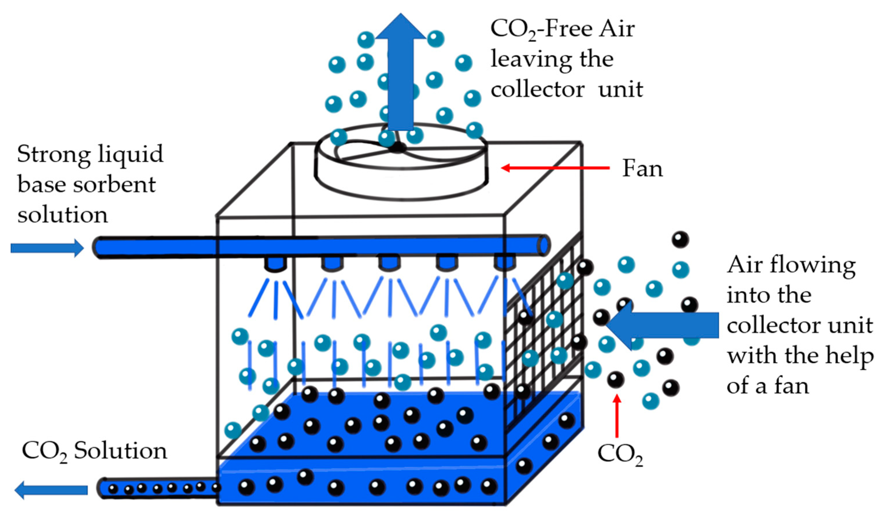
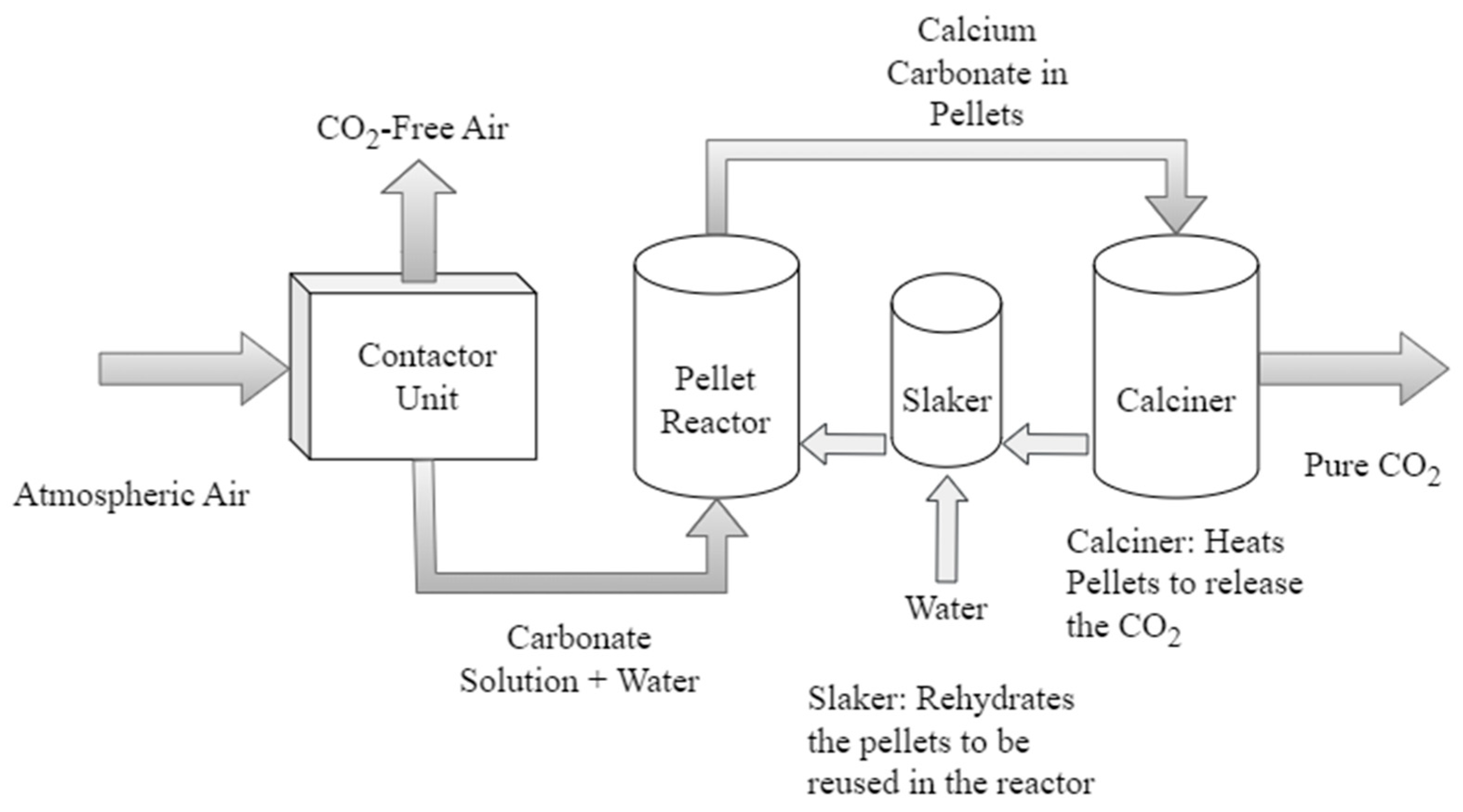
3.1. Absorption Using Liquid Sorbents

In DACCS, based on the absorption of liquid sorbents, ambient air is put in contact with a strong liquid base to dissolve the CO2. Through this procedure, a carbonate solution is created, which is then combined with calcium hydroxide to form a precipitate of calcium carbonate in solid form (Figure 1).
Production in a DACCS plant using liquid solvent starts with atmospheric air being drawn by large fans into the air contactor unit. Inside it, the air is exposed to sorbent material wetted with a strong base such as potassium hydroxide (KOH) or sodium hydroxide (NaOH). The CO2 from the air reacts with the base and yields a carbonate solution and water. The carbonate is combined with calcium hydroxide (Ca(OH)2) and passed to a pellet reactor or precipitator to emerge as calcium carbonate. This solid precipitate is sent to a calciner, where it is heated with oxygen to a temperature of 800 or 900 °C. Pure CO2 and calcium oxide are formed. The CO2 component is compressed to produce highly concentrated gas, and the calcium oxide is combined with water to create calcium hydroxide to be reused in the system [1,5]. A simplified diagram appears in Figure 2.

3.2. Adsorption Using Solid Sorbents

Solid sorbent DACCS technology utilizes amine compounds. They adsorb atmospheric CO2, which is separated from the sorbent material by heating the unit to 100 °C (Figure 3). The process starts with a ventilator driving atmospheric air through the capture unit. In this facility, CO2 reacts chemically with the solid adsorbent material and adheres to it. Once adsorption is complete, the capture unit closes to the environment and desorption begins, with heat below 100 °C delivered. During this heating, the vacuum system operates, removing the CO2 released from the adsorbent. Any water that the sorbent material might have co-adsorbed is separated from CO2 by cooling the gas stream to induce water condensation. The separated CO2 is then delivered as a product slightly above ambient conditions and with a 99.9 percent v/v purity [6]. Once the sorbents are saturated with CO2, they are treated and released for storage in geological formations or usage in other carbon-related applications [1].

4. Comparing DACCS Absorption vs. Adsorption

Additionally, to study DACCS technology more completely, the two alternative production methods should be compared. The key assessment criteria include material usage, locational and infrastructural aspects, operational considerations, energy use, and costs for carbon capture and capital installation.

4.1. Material Usage

In absorption, ambient air is placed in contact with a strong liquid hydroxide base capable of dissolving CO2. The take-up of carbon dioxide in aqueous alkaline solutions is a well-known gas-treating process in the chemical industry [7]. The reaction between the two elements occurs quickly and exothermally in a specific area of the air contactor unit wetted by the alkaline solution. With reference to the high surface area required for the reaction, several types of air-solvent contractors have been investigated, including solid structured packing, liquid sprays, and gas-liquid membrane models. When deciding which type of contactor to use, the saturation speed associated with the different sorbents can be balanced against the energy required to create a large surface.
Via the adsorption approach, chemical compounds (amines or carbonate salts) widely known to adsorb or bind CO2 are introduced. Either type is grafted or deposited into a porous support, creating a large surface area and increasing the exposure of the sorbent materials to air. The sorbent chemicals dominate the active phase. The support materials can be metal oxides (alumina and silica gel), activated carbon, cellulose, or organic polymers. The choice depends on the surface area, pore size distribution, and pore volume. Many combinations are possible. Environmental impacts in the production of the different adsorbents and support materials can similarly be significant in the selection [6]. The reaction mechanism between CO2 and the amine chemicals depends on the type of amine and the environmental conditions. Some amine materials studied for use in DACCS are polyethyleneimine, aminopropylmethyldimethoxysilane, trimethylamine, and potassium carbonate (K2CO3) [6].

4.2. Location and Infrastructure

Central to the implementation of DACCS technologies is water and land usage. Ozkan [8] reports that a plant can require up to seven tonnes of water per tonne of CO2 removed, with fresh (not seawater) supply mandated for the air-sorbent contact stage. Though water demand varies with temperature and relative humidity, DACCS remains the most water-efficient CCS technology [9]. Land usage is only a concern when solar energy is used to supply an integrated DACCS plant. The sense is conveyed by Jakob Stausholm, CEO of Rio Tinto, in his remark that ‘we are used to big sites in mining but quite frankly mining sites are small compared to the scale of these [solar] parks’ [10]. Notably, solar farms have yet to power heavy industry anywhere in the world. Such development will obviously impact other industries charged with providing the minerals to build the necessary solar panels and batteries [11]. In contrast to solutions such as bioenergy with carbon capture and storage (BECCS) and afforestation/reforestation, DACCS itself does not require large tracts of land but instead relies on proximity to abundant water and energy sources [8].
The area necessary for DACCS is influenced by the size of the contactor, its configuration, and the spacing requirement for multiple contactor units. In the absorption method, contactors must be arranged around a centralized regeneration facility for a liquid solvent plant and be positioned such that the CO2-depleted outlet should not feed into the intake of an adjacent contactor [12]. For a one MtCO2/year facility, the direct land required for the contactor units and the regeneration facility is approximately 2.5 hectares, exclusive of any indirect allocation for onsite energy generation from renewable electricity or natural gas power plants. Land costs will naturally vary from locality to locality, and no attempt is made in this paper to estimate them.
For a solid sorbent plant undertaking adsorption, the contactor layout can be very similar to the liquid variant. The respective footprint must accommodate the air/solid contactor unit process equipment, area mixing, and safety margins. Based on current designs to capture one MtCO2/year, the land required can vary from 1.2 to 1.7 hectares. This range covers only the area for the DACCS plant, not for local power generation from renewables or fossil fuels. Depending on the energy source, the surface involved can increase markedly [12].

4.3. Operational Considerations
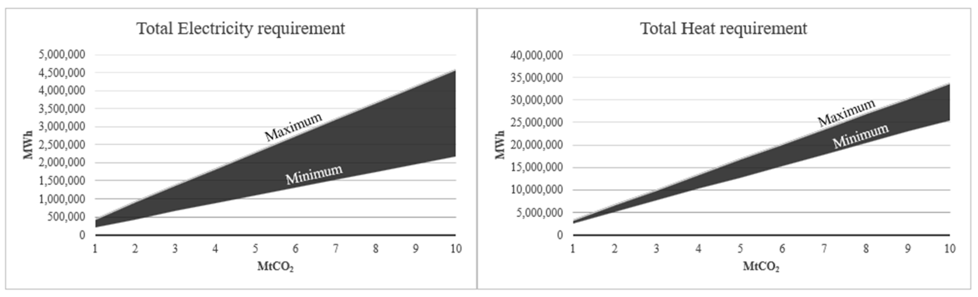
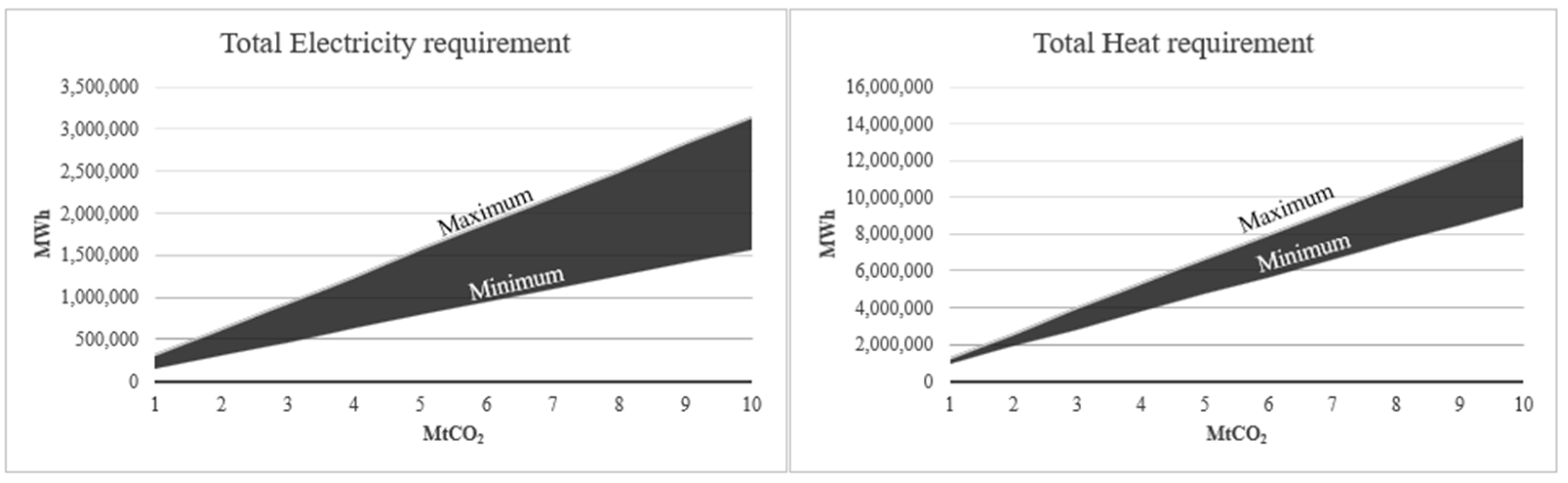
In the absorption process with liquid solvents, the collector can operate continuously. Via the contactor, ambient air is brought into the system naturally or assisted by fans, and the absorption process occurs at room temperature and ambient pressure [13].
Two steps occur in the adsorption process. In the first, ambient air again enters the unit naturally or with fans. CO2 binds to the sorbent material at ambient temperature until the sorbent material is fully saturated. In the second step, the fans are turned off and the unit inlets are closed. CO2 released from the sorbent material by heating is collected and transported out of the system. The collector unit needs to be cooled to ambient conditions before opening the inlets again to start another cycle [13].

4.4. Energy Use

A key issue to consider in DACCS deployment is energy consumption. Depending on the process utilized, the technology entails an electricity- and heat-intensive transformation with temperatures that span from just below 100 °C to 900 °C required for sorbent regeneration (i.e., the release of the concentrated CO2 captured for further processing). As a result, energy requirements range from five to 8.1 GJ per tonne of CO2 captured [14]. This demand can significantly affect the feasibility of DACCS projects, with the location of relevant facilities demanding good sources of renewable (or nuclear) energy coupled with suitable injection sites [15]. Implementing nuclear energy is often hindered by high associated costs and time-consuming approval processes. Building a plant could take 10 to 20 years or more, with many reactors in construction experiencing significant delays and some remaining unfinished after 20 years [16,17,18]. Even though nuclear technology could potentially bring down the cost of low-carbon energy, this article will not further consider it since it could be too late to address the 2050 targets by the time it comes online.
In the absorption method, calcium carbonate (CaCO3) is formed from the reaction of CO2 with strong bases. To decompose this CaCO3 to calcium oxide and release the CO2, considerable energy is required—that is, heat above 700 °C. Current pilot plants heat to 900 °C for high-temperature calcination, with methane typically used for energy production [7].
For liquid solvent absorption, energy and thermal requirements derive from the operation of contactor fans, solvent pumps, the slaker, the causticizer/clarifier, air separation, heater/dryer units, and the calciner. According to the National Academies of Sciences, Engineering, and Medicine [12], an input of 10 to 13.8 GJ/tCO2 is indicated. This estimate does not contemplate any heat recovery from the hydration reaction. Heat recovery is still insufficiently understood due to a lack of experimentation. However, some simulation has been undertaken with Aspen Plus software, and minimum and maximum energy requirements were calculated from vendor parameters. They proved to be affected by ambient conditions, pressure drops in the system array, heat losses, and so on [3]. Most of the energy is required for the CaCO3 preparation for calcination and CO2 liberation, which, as outlined, assumes a temperature of 900 °C. The energy needed for each component in the liquid absorption process is expressed in GJ. The values presented in Table 1 are those used for the subsequent cost estimation according to each specific energy requirement. The escalation of the electricity and heat requirements is linear, as can be seen in the graphs in Figure 4.
In the left graph, the total electricity in MWh required for a liquid solvent absorption DACCS is presented for a plant with a capacity of 1 MtCO2 to 10 MtCO2. In the right graph, the total heat requirement is displayed in MWh for the same facility. The minimum and maximum values on the graph were calculated from a best-case scenario of ambient conditions that allow the plant to work with fewer energy and heat requirements to a worst-case scenario under which the ambient conditions will cause the operation to require more electricity and heat [12].
As applied to the second DACCS variant, solid amine materials employed as adsorbents have, in general, lower specific heat, which reduces the necessary heat for releasing the CO2 captured [7]. A weaker bond between the CO2 and the amine sorbent material is formed, necessitating less energy than required in absorption in order to separate the CO2 from the sorbent material into a strong base [1]. Separation occurs through a combination of changes in pressure, humidity, and temperature, which are typically 100 °C or less.
An advantage of many recent solid sorbent-based (adsorption) DAC initiatives is that they do not require high-temperature thermal energy. The energy demand results from the operation of air contactor fans and desorption vacuum pumps, along with the thermal requirement from the desorption heat, estimated to be 100 °C. In an ideal scenario, the electrical component should be met with renewable energy. Moreover, the thermal contribution could be obtained from low-temperature waste heat if suitable sources are available. Energy variation follows the optimization of heat losses and other parameters [12]. Energy requirements for each stage of solid adsorption are expressed in GJ in Table 2. The escalation of the electricity and heat requirements is linear, as per Figure 5.
In the left graph, the total electricity in MWh required for a solid adsorption DACCS plant is presented for a facility with a capacity of 1 to 10 MtCO2. In the right graph, the total heat requirement in MWh is indicated for the same plant. The minimum and maximum values on the graph were calculated from a best-case scenario of ambient conditions that will allow the plant to work with less energy and heat to a worst-case scenario under which the ambient conditions will cause it to require more electricity and heat [12].

4.5. Carbon Capture Cost

The operating cost of a liquid solvent absorption DAC plant varies with the fuel used for energy generation. The analysis must cover the energy costs for operating the different system parts, maintenance, labor, and waste removal. A cost estimate calculated by the National Academies of Sciences, Engineering, and Medicine [12] was normalized for the separation and capture of CO2 from ambient air. It also presumed the use of natural gas or coal to power the capture plant with an optimized system operating at a 75 percent capture rate. These parameters yield an estimate of 140 to 264 USD per tCO2 removed. Research into DACCS is currently in its early stages. It is common to see quite wide ranges of costs reported in the literature. This spread includes the capital cost annualized with an estimated plant life of 30 years, using a scenario based on optimal parameters from the literature with an overall capital charge factor of 12 percent, which includes interest, depreciation, and taxes [12]. The infrastructure recognized is a plant with a capacity to remove one MtCO2 per year. The intensity associated with the high heating commitment leaves ‘energy’ accounting for 21–24 percent of the total capture cost in this type of DACCS plant.
In a solid adsorption situation, costs accrue from the running of the fans positioned to pass air through the adsorbing material and the heat and vacuum operations for the desorption of CO2. For a generic solid sorbent direct air capture system, the National Academies of Sciences, Engineering, and Medicine [12] estimate a cost of 88 to 228 USD per tCO2 removed, depending on the energy source. This range includes the capital cost annualized with an estimated plant life of 30 years and a charge factor of 12 percent. The infrastructure envisaged is a plant with a capacity to remove one MtCO2 per year. Energy supply accounts for 10–13 percent of the total capture cost.

4.6. Capital Cost

In constructing a liquid solvent absorption plant, the technology uses cheap cooling tower hardware, and the solution can be recycled continuously, allowing for a very long performance lifetime. Building costs include the contactor array, slaker, causticizer, clarificatory, calciner, condenser, water investment, electrolyser, compressors, and pressurizing tanks. Of course, additional capital costs will accrue if a solar photovoltaic plant is dedicated to providing energy for the DACCS.
In a solid sorbent plant, the capital cost includes that of the adsorbent material, the blower and vacuum systems, the condenser, and the contactor. In this technology, the adsorbent material typically has 10 times more surface area compared with liquid solvent systems, reflecting a lower cost and smaller footprint for the contactor units.

5. Global Aspects of DACCS: Commercialization and Institutional Framework

With the essentials of DACCS established, the study tracks its global progress toward commercialization and, equally importantly, its standing as a technology within the international institutional frameworks around climate change and GHG reductions.

5.1. Commercialisation

Little work has assessed the feasibility of DACCS in the southern hemisphere; however, 19 commercial projects are in force worldwide, of which 18 are situated in North America and Europe [19,20]. According to the International Energy Agency [21], the combined capture capacity of these fledgling ventures (in 2021) is approximately 8000 tonnes of CO2 per year. The IEA cautions that DAC technology will need to capture 90 MtCO2 by 2030 and significantly accelerate to 980 MtCO2 per year for the world to reach net-zero by 2050.
In Europe, several research programs and initiatives are exploring the potential of DACCS technologies. For example, the European Commission’s Horizon 2020 research and innovation program has funded several projects related to DACCS. They aim to develop and test new technologies and demonstrate their feasibility on a larger scale [22]. Currently, the largest DACCS plant is operating in Iceland. Known as the ORCA facility, it has been run since September 2021 by the Swiss company Climeworks and is designed around geothermal energy to remove around 4000 tonnes of CO2 annually. Climeworks partners with Carbfix (a firm that specializes in carbon storage), and the CO2 captured is either stored in stone or sold to manufacturers [23]. Climeworks trades on the economic value of removing CO2 and selling credits to companies so they can approach carbon neutrality. It has raised over USD 650 million in equity from private investors and USD 1 billion in debt from Microsoft’s climate-innovation fund [24]. In June 2022, Climeworks initiated its next facility, named Mammoth. It is expected to capture 36,000 tonnes of CO2 per year [25].
In the United Kingdom, Humber Zero CCS is a carbon capture and storage project that aims to create the world’s first zero-carbon industrial cluster. It is tasked with capturing and storing carbon dioxide emissions from various industries, including power generation, cement, and steel production. The plan developed by a consortium of companies is expected to capture up to 17 million tonnes of CO2 per year by 2030 and is a key part of the nation’s efforts to achieve net-zero emissions by 2050 [26].
In the United States, attracted by tax credits of up to USD 180 per tonne of CO2, firms are reportedly eyeing the CCS field with interest. Occidental Petroleum, a Houston-based hydrocarbons corporation, has announced that it seeks to increase its complement of DAC plants from 70 to 100 by 2035 [24]. The Federal Department of Energy (DOE) committed USD 12.5 million in 2019 to fund six research and development projects to advance DACCS technology. In 2021, the Kansas consulting engineer firm Black and Veatch received USD 2.5 million from this fund to build a DAC facility able to remove 100,000 tonnes of CO2 per year [27]. In December 2022, the DOE released guidelines for the award of USD 3.5 billion over the following five years with the intention of rapidly scaling up DAC systems. The funds will be distributed over two prize competitions, with up to USD 1.2 billion to support credible plants that can capture at least one million tonnes of CO2 per year [28].
The most significant undertaking by private enterprise to date comes from a joint venture between the Canadian company Carbon Engineering and its American partner, One Point Five, which plan to build the world’s largest capture plant with the ability to remove one million tonnes of CO2 per year using DAC technology [29,30]. According to Carbon Engineering (2020), the project, to be located in the Texas Permian Basin, is currently in ‘front-end engineering and development’ and should be operational by late 2024. Though scaling-up is thereby in train and these advances in technology represent a significant increase in capability, there is a long way to go to address the reduction targets mandated by the IEA and key international climate change forums.

5.2. Climate Change and CCS

In 2015, the Paris Agreement was signed as a successor to the Kyoto Protocol [31]. The legally binding arrangement came into effect in November 2016 and has been joined by 193 parties committed to reducing country emissions and shifting towards net-zero [32]. As part of the pact, each participant must publicly communicate and record its commitments in the form of nationally determined contributions (NDCs), intended to be updated and strengthened every five years [33]. However, probabilistic estimations of carbon intensity (CO2 emissions per unit of GDP) such as the one presented by Raftery et al. [34] indicate the need for rapid decarbonization. These authors contend that carbon emissions for most nations have peaked, after which point output intensity tends to decline.
Scenarios developed by the IPCC for climate mitigation suggest that the rapid decarbonization of energy and material services will be insufficient to contain gains in global mean temperature below the targets [35]. In their appraisal, Raftery et al. [34] use a calibrated Bayesian hierarchical model that indicates the carbon intensity peak, cumulative distributions of CO2, and the post-peak trend. It determines that, if current trends do not change, the probability of keeping the gain in global mean temperature below 2 °C compared with the preindustrial level is less than five percent, while there is anyway less than a one percent chance to hold it below 1.5 °C [36]. These predictions obviously question what else needs to be done if the world is to meet the established Paris global temperature objectives.
One route examined in the agreement relates to NETs [1]. Most IPCC scenario modeling contemplates using CDR among the NETs to eliminate excess atmospheric carbon [35]. CDR discussions have gravitated toward BECCS and forestry to offset GHG emissions. The IEA and the IPCC have defined CDR technologies as integral (i.e., contributing 15 percent) to the reduction of atmospheric CO2 to achieve net-zero global decarbonization goals by 2050 [37]. As pointed out by Fuhrman et al. [38], CDR measures have the advantage that their foundations already exist but will require extensive land usage if fossil fuel energy sources are to be dispensed with. Hence, despite any favorable groundswell of opinion, the feasibility of large-scale CDR deployment has been described as uncertain, and over-reliance on this technology within the IPCC scenarios has been criticized [39].
The contrary (i.e., pro-CDR) case relies in part on historical precedent. The IPCC floated the potential for CCS as a mitigation technology in a special report in 2005 [40]. Martin Roberts et al. [37] credit the first efforts to launch such technologies worldwide to the inter-governmental forum of the Group of Eight (G8) countries in 2008. At the time, the aim was to roll out at least 10 large-scale CCS demonstration projects by 2010. Due to the cost of implementation and the failure to comply with political commitments, these goals failed to materialize at the scale required. Later, the United Nations Framework Convention on Climate Change (UNFCCC) asked the IPCC to provide a special report on the impact of global warming at 1.5 °C above preindustrial levels [41]. It appeared (SR15) in 2018 [42] and, among its integrated assessment climate models, rehearsed DACCS, then a new technology for negative CO2 emissions [40]. Given its restrained adverse impacts, it is regarded by many as offering a large-scale and permanent solution for excess CO2 [1,40].
Studies have canvassed the critical role that DACCS could play in meeting the IPCC targets based on its inclusion in integrated assessment modeling (IAM) scenarios. These papers do not overlook the significant land, water, and energy costs of deploying DACCS on a large scale [35]. On one hand, as Fuhrman et al. [43] mention, DACCS can reduce the more appreciable trade-offs associated with land and fertilizer required for BECCS and afforestation. On the other hand, it is an energy-demanding technology, especially when broadly deployed, and needs access to power grids [2,35]. Energy use determines the GHG emissions in the system, with approximately 65 percent arising from electric energy demand and 32 percent from heat requirements.
Current political and regulatory frameworks are not supporting the development of CCS as a mitigation technology. For instance, the European Union Emissions Trading Scheme (EU-ETS), the world’s largest carbon pricing mechanism, allows for continued CO2 emissions while increasing permit prices, discouraging the use of CCS. Similarly, tax credits in the United States to incentivize the use of CO2 in enhanced oil recovery do not require verifiable storage of the gas [44]. According to Haszeldine et al. [44], political and regulatory adaptations should create equal value between emissions reduction and CO2 storage to stimulate rapid storage with minimum oversight. A good example of a simple and direct linkage that resulted in direct action to capture, inject, and store COS is the Norwegian tax on offshore hydrocarbon production emissions of GHGs, which could be replicated worldwide to reduce associated emissions from hydrocarbon production [44].
Most recently, as part of its sixth assessment report (AR6), the IPCC Working Group III (WG3) explained developments in emission reduction and mitigation efforts and examined the impact of the individual national climate pledges concerning long-term goals. The WG3 assessed multiple future emission scenarios and climate mitigation strategies [45]. For the first time, CDR is mentioned as a critical means to limit global warming. All the mitigation pathways assessed use land-based CDR technology, or BECCS; certain scenarios co-opt DACCS. The report stipulates more political commitment, policymaking, and investment to accelerate research, development, and demonstration of CDR technologies [46]. We turn now to the Australian response to this call.

6. The Australian Context for DACCS

6.1. Policy Settings

Given the expanding nexus between commercial and policy initiatives, some countries are starting to integrate CCS technology as part of their NDCs. For example, the United Kingdom aims to sequester at least 5 Mt of CO2 per year using engineered GHG gas removal (GGR) technologies, including DACCS, BECCS, biochar, and enhanced weathering. However, the cost of CCS technologies and the lack of infrastructure to transport and store CO2 have hindered large-scale commercial deployment. In addition to delivering negative emissions, the United Kingdom’s policy efforts supporting GGR technologies currently focus on research and innovation, the designation of CCS clusters, and a GBP 1 billion carbon capture and storage infrastructure fund [47].
Similarly, Australia in October 2021 updated its NDC to commit to net-zero by 2050 through seven low-emission technologies within a long-term reduction plan and a Technology Investment Roadmap [48]. As part of this ensemble, CCS attracts a proposed investment of over AUD 300 million. Australia has a competitive advantage in implementation due to its sizeable geological storage basins and proximity to mining and other industries producing highly concentrated CO2 emissions [48]. Although the Roadmap presented by the federal government mentions that CCS technologies will contribute significantly to the net-zero goals, no information emerges as to how the relevant modeling was undertaken. This much is certain: a projected increase in national fossil fuel exports by mid-century will make reliance on CCS or other offsets important to achieving the Paris targets. So, how economically viable could a technology such as DACCS be in the Australian context?

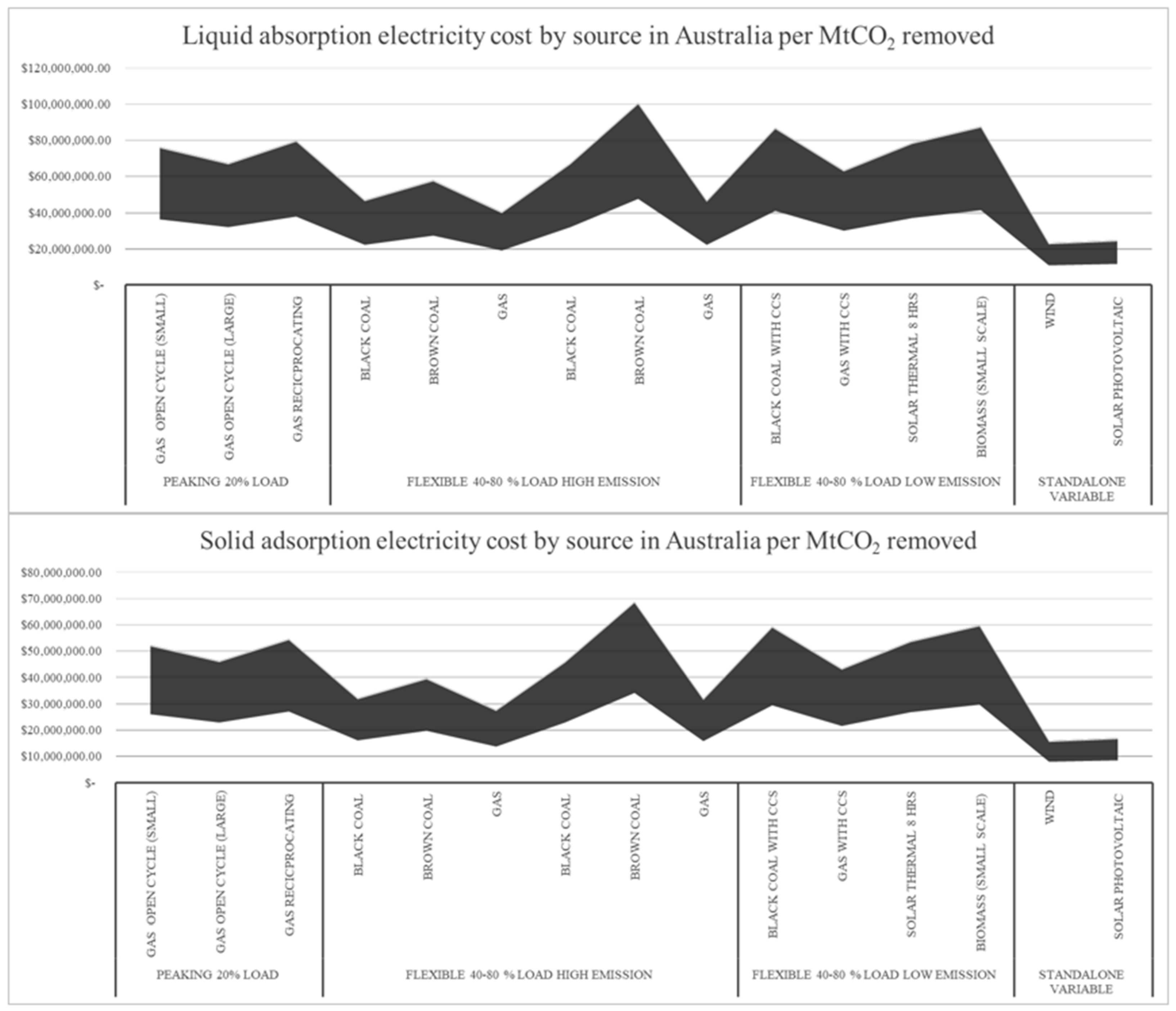
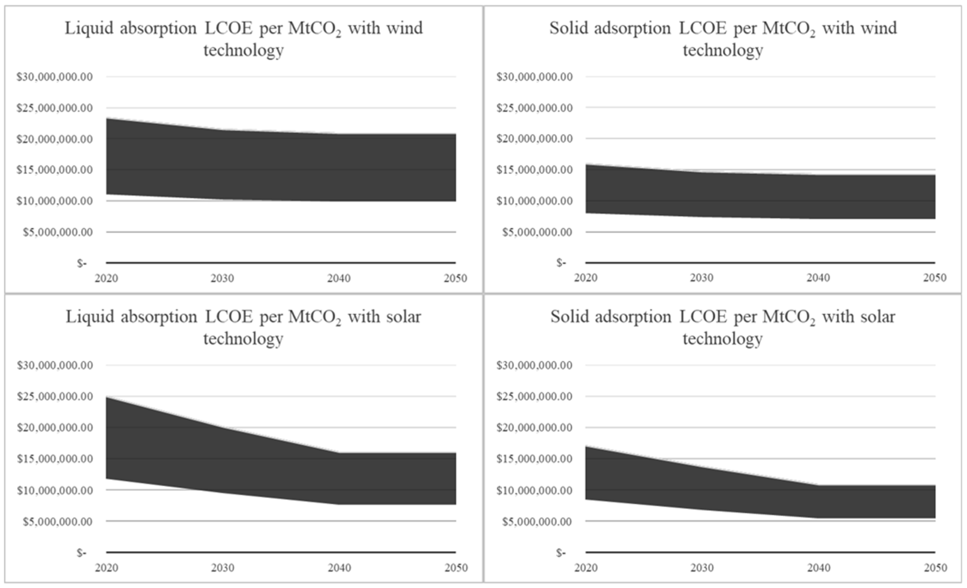
6.2. Economic Viability of DACCS

In order to answer the above question, a two-step analysis is needed. It is not merely ‘speculative’ but should be regarded as ‘indicative’ rather than ‘definitive’, given the absence of NET projects and limited financial information about them in Australia. Amplifying the foregoing technical summary, a comparison of capture and capital costs for DACCS absorption and adsorption is first needed. Second, the results of that exercise should be calibrated with contemporary energy costs in Australia.
Discussion ideally begins with the comment that, though DACCS is a cutting-edge CCS alternative, it is not necessarily a high-technology operation in regard to either its material usage or plant componentry. The technical challenge is processing large volumes of air to extract small concentrations of CO2. The system can create considerable pressure drops inside the contactor units, controlled by expensive capital equipment and energy inputs to keep the air moving in the plant. As is well known in other industries, ancillary system components suffer similar problems (e.g., the slaker, causticizer, and clarificatory). Thus, the operation moves beyond known technology regarding cooling towers; the integration of DACCS componentry comes with significant learning commitments, especially in endeavors to scale up the output of CO2.
An overall cost comparison between the two DACCS variants appears in Table 3. Entries were calculated from electricity requirement data from the National Academies of Sciences, Engineering, and Medicine [12], using an American cost of 0.06 USD/KWh for electricity and 3.25 USD per GJ for natural gas required for heating. In Australia, the respective prices are much higher, reported (ex-Brisbane) by the Australian Energy Regulator [49] as being 0.167 USD/KWh for electricity and 9.42 USD/GJ for natural gas. Keeping other plant and institutional cost factors the same (i.e., ceteris paribus), an international comparison of DACCS electricity and heating costs is provided in Table 4.
The apparently high plant establishment costs displayed in Table 3 are well-referenced and plausible given the scope of public subventions for CCS being contemplated overseas. Applying Australian prices exclusive of capital costs, the total energy cost becomes 123 to 192 USD/tCO2 for liquid absorption and 58 to 98 USD/tCO2 for solid adsorption technology. The two DACCS production methods have specific footprints and energy consumption, implying different capital and operating investments. Superimposed upon this observation is uncertainty about the actual cost of implementation; divergent figures typically circulate within the private and academic sectors [51]. Keith et al. [3] published the first paper with a commercial engineering breakdown for a 1 MtCO2/year DACCS plant, and the approach of his team has informed the foregoing tables and figures. Costs as low as 100 USD and as high as 600 USD per tonne of CO2 captured have been reported [52]. Regarding energy, Australia is one of the top 10 global producers. It relies heavily on coal for electricity production [53]. Fossil fuels generate 71 percent, and renewables only 29 percent of the energy delivered [54]. Interstate variations also occur: in Queensland, for example, renewables comprise less than 20 percent of the energy mix. Being a large user of both water and energy, DACCS will clearly have to eschew expensive solutions and rely on cheap sources of each commodity [55,56].
As indicated by Temple [57], many countries rely on large amounts of carbon removal to achieve their net-zero plans, but no clear pathway to implement the technology has been presented by any one of them. Proof is indicated that the technology is easily scalable. Thus, carbon-free electricity is required for the technology to be feasible; otherwise, and futilely, the operation will release more CO2 into the atmosphere than it captures [58]. A joint leadership effort from industrialized economies is needed, taking advantage of regional characteristics that can promote cooperation and the advancement of technology [59].
The Commonwealth Scientific and Industrial Research Organization (CSIRO), in its GenCost 2021–2022 Consultation Draft, presents the levelized cost of electricity (LCOE) from a range of generation techniques [60]. Wind and solar emerge as the cheapest sources of new supply (Figure 6). With planned integration, their costs are predicted to fall compared with those of new fossil fuel electricity plants, which should remain unchanged over the next three decades [61].
These LCOE values can help estimate the total cost of electricity for a DACCS plant if one were to be built in Australia. In Figure 7, assuming a best-case (renewables) cost scenario and using the average LCOE for 2020, we see that the electricity cost for a liquid absorption DACCS plant can be as low as AUD 8 million per MtCO2. On the same basis, a solid sorbent installation in optimal ambient conditions could operate at a cost of AUD 5 million per MtCO2 removed (Figure 8).
The total cost is for a 1 MtCO2 plant. The black area shows the minimum and maximum values and was calculated from the best-case scenario ambient conditions that will allow the plant to work with less energy and heat requirements to the worst-case scenario ambient conditions that will cause the facility to require more electricity and heat [12,60].
The total cost is for a 1 MtCO2 plant. The shaded area represents the minimum and maximum values, calculated from a best-case scenario of ambient conditions that allow the plant to work with less energy and heat to a worst-case scenario in which the ambient conditions will cause the facility to require more electricity and heat [12,60].
Apart from debate over a facilitating regulatory framework (i.e., involving a carbon price and a market for captured CO2 credits), the issue in any DACCS initiative will inevitably be who is to pay for the establishment and running of plants and the implications if costs fall on different sectors of society [62]. Economics and equity come to the fore as governments acknowledge CDR technologies as integral to their commitment to Net-Zero (e.g., the United Kingdom [62]). Australia’s Technology Investment Roadmap within its GHG emissions policy incorporates a financial strategy to support selected processes such as DACCS [63]. The latter are mostly judged controversial by the public and contrary to the conventional (renewable energy) routes to decarbonization.
There is the risk that, if measures fail to mitigate regressive impacts, costs could be greater for low- than high-income groups. After extensive modeling, Owen et al. [62] found that the former will be disproportionately affected unless measures to fund the technologies are weighted by a household’s contribution to the total country’s income tax payments. Sovacool et al. [15] list several approaches toward funding. The first would be to integrate DACCS into a carbon tax emission trading system, with credits awarded for negative emissions. A second would replace existing carbon pricing schemes with carbon removal obligations, and a third advocates placing the obligation for removing carbon back on the emitting industries.

7. Conclusions

This article fills a critical research gap concerning NETs by providing a comprehensive overview of DACCS plants, their commercialization, and their reception in Australia.
‘State-of-the-art’ reports and ongoing research are crucial for Australia’s goal of achieving net-zero emissions by 2050 through CCS technologies. However, more information is needed on the real-life costs of deploying and operating DACCS facilities. Our findings show that, while the construction costs of absorption and adsorption plants are similar, a liquid sorbent plant requires more than double the energy for heating. This divergence is significant, as heat and water are costly resources.
High energy prices in Australia increase CO2 capture costs by up to 60% compared with the United States. The viability of building and operating a DACCS facility in either nation could expand considerably if renewable generation technologies become cheaper and energy is solely derived from these sources, as predicted by the CSIRO. Additionally, with competition in construction increasing, the capital costs of a plant will likely decrease over time.
Furthermore, academics and policymakers need to be well-informed about DACCS and other NETs to enable a proper interdisciplinary appraisal and debate. The major research issues include the dimensions of the carbon market, regulatory and funding frameworks, and a downstream issue well beyond the scope of this article, namely the technology and commercial viability of geological storage of captured carbon.

Author Contributions

Conceptualization, D.G. and P.D.; methodology, D.G. and P.D.; validation, D.G., P.D. and D.W.; formal analysis, D.G., P.D. and D.W.; investigation, D.G.; resources, D.G.; data curation, D.G. and P.D.; writing—original draft preparation, D.G. and D.W.; writing—review and editing, D.G. and D.W.; visualization, D.G., P.D. and D.W.; supervision, P.D. All authors contributed equally to this work. All authors have read and agreed to the published version of the manuscript.

Funding

This research received no external funding.

Data Availability Statement

The data presented in this study is contained within the article and available in the reference list.

Conflicts of Interest

The authors declare no conflict of interest.

References

  1. Gambhir, A.; Tavoni, M. Direct Air Carbon Capture and Sequestration: How It Works and How It Could Contribute to Climate-Change Mitigation. One Earth 2019, 1, 405–409. [Google Scholar] [CrossRef]
  2. Chen, C.; Tavoni, M. Direct air capture of CO2 and climate stabilization: A model based assessment. Clim. Chang. 2013, 118, 59–72. [Google Scholar] [CrossRef]
  3. Keith, D.W.; Holmes, G.; St Angelo, D.; Heidel, K. A Process for Capturing CO2 from the Atmosphere. Joule 2018, 2, 1573–1594. [Google Scholar] [CrossRef]
  4. Sanz-Pérez, E.S.; Murdock, C.R.; Didas, S.A.; Jones, C.W. Direct Capture of CO2 from Ambient Air. Chem. Rev. 2016, 116, 11840–11876. [Google Scholar] [CrossRef]
  5. Long-Innes, R.; Struchtrup, H. Thermodynamic loss analysis of a liquid-sorbent direct air carbon capture plant. Cell Rep. Phys. Sci. 2022, 3, 100791. [Google Scholar] [CrossRef]
  6. Deutz, S.; Bardow, A. Life-cycle assessment of an industrial direct air capture process based on temperature–vacuum swing adsorption. Nat. Energy 2021, 6, 203–213. [Google Scholar] [CrossRef]
  7. Brilman, W. CO2 removal from air. Adv. Carbon Capture 2020, 523–543. [Google Scholar] [CrossRef]
  8. Ozkan, M. Direct Air Capture of CO2: A Response to Meet the Global Climate Targets. MRS Energy Sustain. 2021. [Google Scholar] [CrossRef]
  9. Rosa, L.; Sanchez, D.L.; Realmonte, G.; Baldocchi, D.; D’Odorico, P. The Water Footprint of Carbon Capture and Storage Technologies. Renew. Sustain. Energy Rev. 2021, 138, 110511. [Google Scholar] [CrossRef]
  10. van Leeuwin, H. ‘We are fooling ourselves on the timeline’: Rio’s warning on solar. Aust. Financ. Rev. 2023, 20, 17. [Google Scholar]
  11. Rae, M. Aussies Not ‘Fooling Ourselves’ on Solar. 2023. Available online: https://www.perthnow.com.au/business/aussies-not-fooling-ourselves-on-solar-c-9508765 (accessed on 23 January 2023).
  12. National Academies of Sciences, Engineering, and Medicine. Negative Emissions Technologies and Reliable Sequestration: A Research Agenda; National Academies Press: Washington, DC, USA, 2019. [Google Scholar]
  13. Fasihi, M.; Efimova, O.; Breyer, C. Techno-economic assessment of CO2 direct air capture plants. J. Clean. Prod. 2019, 224, 957–980. [Google Scholar] [CrossRef]
  14. Madhu, K.; Pauliuk, S.; Dhathri, S.; Creutzig, F. Understanding Environmental Trade-Offs and Resource Demand of Direct Air Capture Technologies through Comparative Life-Cycle Assessment. Nat. Energy 2021, 6, 1035–1044. [Google Scholar] [CrossRef]
  15. Sovacool, B.K.; Baum, C.M.; Low, S.; Roberts, C.; Steinhauser, J. Climate policy for a Net-Zero future: Ten recommendations for Direct Air Capture. Environ. Res. Lett. 2022, 17, 074014. [Google Scholar] [CrossRef]
  16. Buongiorno, J.; Corradini, M.; Parsons, J.; Petti, D. Nuclear Energy in a Carbon-Constrained World: Big Challenge and Big Opportunities. IEEE Power Energy Mag. 2019, 17, 69–77. [Google Scholar] [CrossRef]
  17. Jacobson, M. The 7 Reasons Why Nuclear Energy is Not the Answer to Solve Climate Change. 2022. Available online: https://www.oneearth.org/the-7-reasons-why-nuclear-energy-is-not-the-answer-to-solve-climate-change/ (accessed on 11 September 2022).
  18. Kurmelovs, R. Explainer: Should Australia Build Nuclear Power Plants to Combat the Climate Crisis? The Guardian. 2021. Available online: https://www.theguardian.com/environment/2021/oct/13/explainer-should-australia-build-nuclear-power-plants-to-combat-the-climate-crisis (accessed on 11 September 2022).
  19. Bourzac, K. We have the technology. Nature 2017, 550, 66–69. [Google Scholar] [CrossRef]
  20. Masterson, V. Companies are Sucking Carbon from the Atmosphere Using ‘Direct Air Capture’. How Does it Work? 2022. Available online: https://climatechampions.unfccc.int/companies-are-sucking-carbon-from-the-atmosphere-using-direct-air-capture-how-does-it-work/ (accessed on 16 January 2023).
  21. IEA. Direct Air Capture 2022. 2022. Available online: https://www.iea.org/reports/direct-air-capture-2022 (accessed on 16 January 2023).
  22. Directorate-General for Climate Action Carbon Removals: A Strong Ally to Achieve Climate Neutrality in the EU. Available online: https://climate.ec.europa.eu/news-your-voice/news/carbon-removals-strong-ally-achieve-climate-neutrality-eu-2023-02-17_en (accessed on 19 April 2023).
  23. Climeworks. The Next Step towards a Climate-Positive World: Orca! 2021. Available online: https://climeworks.com/roadmap/orca (accessed on 17 January 2023).
  24. Ramkumar, A. Climate Startup Removes Carbon From Open Air in Industry First. 2023. Available online: https://www.wsj.com/articles/climate-startup-removes-carbon-from-open-air-in-industry-first-11673492767 (accessed on 16 January 2023).
  25. Calma, J. Construction Begins on ‘Mammoth’ Direct Air Capture Plant. 2022. Available online: https://www.theverge.com/2463 (accessed on 16 January 2023).
  26. O’Beirne, P.; Battersby, F.; Mallett, A.; Aczel, M.; Makuch, K.; Workman, M.; Heap, R. The UK Net-Zero Target: Insights into Procedural Justice for Greenhouse Gas Removal. Environ. Sci. Policy 2020, 112, 264–274. [Google Scholar] [CrossRef]
  27. Black and Veatch and Global Thermostat. Black and Veatch Awarded DOE Funding to Build Global Thermostat DACProject to Capture 100,000 Tons of CO2. Global Thermostat. 2021. Available online: https://globalthermostat.com/2021/07/black-veatch-awarded-doe-funding-to-build-global-thermostat-dac-project-to-capture-100000-tons-of-co2/ (accessed on 17 January 2023).
  28. Hiar, C.; Anchondo, C. DOE Releases Record Funding for Removing Carbon. 2022. Available online: https://www.eenews.net/articles/doe-releases-record-funding-for-removing-carbon/ (accessed on 2 August 2022).
  29. Carbon Engineering. Oxy Low Carbon Ventures, Rusheen Capital Management Create Development Company 1PointFive to Deploy Carbon Engineering’s Direct Air Capture Technology. 2020. Available online: https://carbonengineering.com/news-updates/new-development-company-1pointfive-formed/ (accessed on 17 January 2023).
  30. Günther, A. ISIpedia. 2021. Available online: https://www.isipedia.org/report/the-paris-agreement-and-ndcs-are-the-national-mitigation-targets-sufficient-to-stay-below-the-1-5-2-c-limit/?origin=isipedia-rss (accessed on 2 August 2022).
  31. One Point Five. Construction of World’s Largest Direct Air Capture Plant in the Texas Permian Basin. 2022. Available online: https://www.1pointfive.com/worlds-largest-direct-air-capture-plant-in-the-texas-permian-basin (accessed on 17 January 2023).
  32. United Nations. The Paris Agreement. 2021. Available online: https://www.un.org/en/climatechange/paris-agreement (accessed on 3 August 2022).
  33. Vogt-Schilb, A.; Hallegatte, S. Climate policies and nationally determined contributions: Reconciling the needed ambition with the political economy. Wiley Interdiscip. Rev. Energy Environ. 2017, 6, 256–587. [Google Scholar]
  34. Raftery, A.E.; Zimmer, A.; Frierson, D.M.W.; Startz, R.; Liu, P. Less than 2 °C warming by 2100 unlikely. Nat. Clim. Chang. 2017, 7, 637–641. [Google Scholar] [CrossRef]
  35. Qiu, Y.; Lamers, P.; Daioglou, V.; McQueen, N.; de Boer, H.-S.; Harmsen, M.; Wilcox, J.; Bardow, A.; Suh, S. Environmental trade-offs of direct air capture technologies in climate change mitigation toward 2100. Nat. Commun. 2022, 13, 3635. [Google Scholar] [CrossRef]
  36. Liu, P.R.; Raftery, A.E. Country-based rate of emissions reductions should increase by 80 percent beyond nationally determined contributions to meet the 2 °C target. Commun. Earth Environ. 2021, 2, 29. [Google Scholar] [CrossRef]
  37. Martin-Roberts, E.; Scott, V.; Flude, S.; Johnson, G.; Haszeldine, R.S.; Gilfillan, S. Carbon capture and storage at the end of a lost decade. One Earth 2021, 4, 1569–1584. [Google Scholar] [CrossRef]
  38. Fuhrman, J.; Clarens, A.; Calvin, K.V.; Doney, S.C.; Edmonds, J.A.; O’Rourke, P.; Patel, P.L.; Pradhan, S.; Shobe, W.; McJeon, H.C. The role of direct air capture and negative emissions technologies in the Shared Socioeconomic Pathways towards +1.5 °C and +2 °C futures. Environ. Res. Lett. 2021, 16, 114012. [Google Scholar] [CrossRef]
  39. Grant, N.; Hawkes, A.; Mittal, S.; Gambhir, A. The policy implications of an uncertain carbon dioxide removal potential. Joule 2021, 5, 2593–2605. [Google Scholar] [CrossRef]
  40. Romanak, K.; Fridahl, M.; Dixon, T. Attitudes on Carbon Capture and Storage (CCS) as a Mitigation Technology within the UNFCCC. Energies 2021, 14, 629. [Google Scholar] [CrossRef]
  41. IPCC. (n.d.) FAQ Chapter 1—Global Warming of 1.5 °C. Available online: https://www.ipcc.ch/sr15/faq/faq-chapter-1/ (accessed on 11 September 2022).
  42. Masson-Delmotte, V.; Zhai, P.; Pörtner, H.-O.; Roberts, D.; Skea, J.; Shukla, P.; Pirani, A.; Moufouma-Okia, W.; Péan, C.; Pidcock, R.; et al. Global Warming of 1.5 °C: An IPCC Special Report on the Impacts of Global Warming of 1.5 °C above Pre-Industrial Levels and Related Global Greenhouse Gas Emission Pathways, in the Context of Strengthening the Global Response to the Threat of Climate Change, Sustainable Development, and Efforts to Eradicate Poverty Edited by Science Officer Science Assistant Graphics Officer. 2019. Available online: https://www.ipcc.ch/site/assets/uploads/sites/2/2019/06/SR15_Full_Report_High_Res.pdf (accessed on 12 September 2022).
  43. Fuhrman, J.; McJeon, H.; Patel, P.; Doney, S.C.; Shobe, W.M.; Clarens, A.F. Food–energy–water implications of negative emissions technologies in a +1.5 °C future. Nat. Clim. Chang. 2020, 10, 920–927. [Google Scholar] [CrossRef]
  44. Haszeldine, R.S.; Flude, S.; Johnson, G.; Scott, V. Negative Emissions Technologies and Carbon Capture and Storage to Achieve the Paris Agreement Commitments. Philos. Trans. R. Soc. A Math. Phys. Eng. Sci. 2018, 376, 20160447. [Google Scholar] [CrossRef]
  45. Kikstra, J.S.; Nicholls, Z.R.J.; Smith, C.J.; Lewis, J.; Lamboll, R.D.; Byers, E.; Sandstad, M.; Meinshausen, M.; Gidden, M.J.; Rogelj, J.; et al. The IPCC Sixth Assessment Report WGIII Climate Assessment of Mitigation Pathways: From Emissions to Global Temperatures. 2022. Available online: https://egusphere.copernicus.org/preprints/2022/egusphere-2022-471/ (accessed on 6 August 2022).
  46. IPCC. Climate Change 2022: Mitigation of Climate Change. 2022. Available online: https://www.ipcc.ch/report/ar6/wg (accessed on 29 August 2022).
  47. Pareliussen, J.; Crowe, D.; Kruse, T.; Glocker, D. Policies to Reach Net Zero Emissions in the United Kingdom. Available online: https://www.oecd-ilibrary.org/content/paper/f6625f01-en (accessed on 19 April 2023).
  48. Australian Government Affirming Australia’s Net Zero Emissions by 2050 Target. Available online: https://www.dcceew.gov.au/about/news/affirming-australias-net-zero-emissions-by-2050-target (accessed on 30 August 2022).
  49. Australian Energy Regulator. Gas Market Prices. 2020. Available online: https://www.aer.gov.au/wholesale-markets/wholesale-statistics/gas-market-prices (accessed on 14 October 2022).
  50. Socolow, R.; Desmond, M.; Aines, R.; Blackstock, J.; Bolland, O.; Kaarsberg, T.; Lewis, N.; Mazzotti, M.; Pfeffer, A.; Sawyer, K. Direct air capture of CO2 with chemicals: A technology assessment for the APS Panel on Public Affairs. Am. Phys. Soc. 2011. Available online: https://infoscience.epfl.ch/record/200555?ln=en (accessed on 16 January 2023).
  51. Ishimoto, Y.; Sugiyama, M.; Kato, E.; Moriyama, R.; Tsuzuki, K.; Kurosawa, A. Putting Costs of Direct Air Capture in Context. SSRN Electron. J. 2017. [Google Scholar] [CrossRef]
  52. Gertner, J. The Dream of Carbon Air Capture Edges toward Reality. 2021. Available online: https://e360.yale.edu/features/488dream-of-co2-air-capture-edges-toward-reality (accessed on 6 March 2022).
  53. Lucas, A. Fossil Networks and Dirty Power: The Politics of Decarbonisation in Australia. In Handbook of Anti-Environmentalism; Edward Elgar Publishing: Cheltenham, UK, 2022; pp. 192–215. Available online: https://www.elgaronline.com/view/edcoll/9781839100215/9781839100215.00020.xm526 (accessed on 4 August 2022).
  54. Australian Government. Electricity Generation. 2020. Available online: https://www.energy.gov.au/data/electricity-generation (accessed on 4 August 2022).
  55. Geoengineering Monitor. Carbon Capture Use and Storage (Technology Briefing). Available online: https://www.geoengineeringcapture-use-and-storage/ (accessed on 7 August 2022).
  56. De la Garza, A. Carbon Removal Is Having a Moment. Not Everyone is Thrilled. 2021. Available online: https://time.com/6125303/direct-air-carbon-capture-infrastructure/ (accessed on 8 August 2022).
  57. Temple, J. Carbon Removal Hype is Becoming a Dangerous Distraction. 2021. Available online: https://www.technologyreview.com/2021/07/08/1027908/carbon-removal-hype-is-a-dangerous-distraction-climate-change/ (accessed on 4 August 2022).
  58. Ranjan, M.; Herzog, H.J. Feasibility of air capture. Energy Procedia 2011, 4, 2869–2876. [Google Scholar] [CrossRef]
  59. Schreyer, F.; Luderer, G.; Rodrigues, R.; Pietzcker, R.C.; Baumstark, L.; Sugiyama, M.; Brecha, R.J.; Ueckerdt, F. Common but differentiated leadership: Strategies and challenges for carbon neutrality by 2050 across industrialized economies. Environ. Res. Lett. 2020, 15, 114016. [Google Scholar] [CrossRef]
  60. Graham, P.; Hayward, J.; Foster, J.; Havas, L. GenCost 2021–2022 Consultation Draft. 2021. Available online: https://publications.csiro.au/publications/publication/PIcsiro:EP2021-3374 (accessed on 8 October 2022).
  61. Mazengarb, M. CSIRO GenCost: Wind and Solar Still Reign Supreme as Cheapest Energy Sources. 2021. Available online: https://reneweconomy.com.au/csiro-gencost-wind-and-solar-still-reign-supreme-as-cheapest-energy-sources/ (accessed on 14 October 2022).
  62. Owen, A.; Burke, J.; Serin, E. Who pays for BECCS and DACCS in the UK: Designing equitable climate policy. Clim. Policy 2022, 22, 1050–1068. [Google Scholar] [CrossRef]
  63. Geroe, S. Technology not taxes: A viable Australian path to Net Zero emissions? Energy Policy 2022, 165, 112945. [Google Scholar] [CrossRef]
Figure 1. Contactor unit diagram of a direct air carbon capture system using liquid sorbent. (Source: authors).
Energies 16 04090 g001
Figure 2. Absorption using the liquid sorbent DACCS process. (Source: authors).
Energies 16 04090 g002
Figure 3. Adsorption using the solid sorbent DACCS process, (Source: authors).
Energies 16 04090 g003
Figure 4. Absorption charts (Source: authors).
Energies 16 04090 g004
Figure 5. Adsorption charts (Source: Authors).
Energies 16 04090 g005
Figure 6. Average Levelized Cost of Electricity (LCOE) over the next three decades for new generation supply by technology per MWh [60] (Data sourced as reported in the literature in AUD, exchange rate of 0.67 AUD per 1 USD used when needed elsewhere in this paper).
Energies 16 04090 g006
Figure 7. Electricity cost by generation technology using average LCOE from CSIRO for 2020 [22].
Energies 16 04090 g007
Figure 8. Electricity cost for wind and solar generation using average LCOE from CSIRO for 2020 [60].
Energies 16 04090 g008
Table 1. Energy required in GJ for each step of the operation for a Liquid Solvent Absorption type DACCS plant [12].
Unit OperationMin GJ/tCO2Max GJ/tCO2Type
Contactor Fans0.321.18Electricity
Solvent Pump0.0480.065Electricity
Slaker0.0050.005Electricity
Causticizer/clarifier0.1090.109Electricity
Air Separation Unit0.30.3Electricity
Heater/dryer3.183.18Thermal/Heat
Oxy-fired calciner69Thermal/Heat
Total9.96213.839
Table 2. Energy required in GJ for each step of the operation for a Solid Adsorption type DACCS plant [12].
Unit OperationMin GJ/tCO2Max GJ/tCO2Type
Desorption Heat (100 °C)3.44.8Heat
Air Contactor Fans0.551.12Electricity
Desorption Vacuum Pump1.10 × 10−21.40 × 10⁻²Electricity
Total3.9615.934
Table 3. Summary economic comparison between the two major technologies for DACCS [12].
Absorption ProcessAdsorption Process
System Type MaterialLiquid Solvent Potassium Hydroxide/Sodium HydroxideSolid Sorbent Amine Compound/Carbonate Salts
OperationContinuousBatch Operation
Temperature required for separation of CO2 from solvent/sorbent material900 °C100 °C
Footprint for MtCO2/year2.42 ha1.2–1.7 ha
Energy requirement GJ/tCO210–13.83.95–5.92
Capture Cost USD/tCO2140–26488–228
Capital Cost for a 1
MtCO2/year plant (Million USD)
675–1255 *633–1708 *
* Prices quoted from industry sources with a 4.5 multiplier factor to account for all equipment and associated components [50].
Table 4. Energy cost, electricity, and gas for DACCS plants, United States and Australia.
Liquid AbsorptionSolid Absorption
United StatesAustraliaUnited StatesAustralia
Electricity
USD/tCO2
13 to 2836 to 779 to 1926 to 53
Heating
USD/tCO2
30 to 4086 to 11511 to 1632 to 45
Total USD/tCO243 to 68123 to 19220 to 3558 to 98
Disclaimer/Publisher’s Note: The statements, opinions and data contained in all publications are solely those of the individual author(s) and contributor(s) and not of MDPI and/or the editor(s). MDPI and/or the editor(s) disclaim responsibility for any injury to people or property resulting from any ideas, methods, instructions or products referred to in the content.

