Article

Sustainability of the Permanent Magnet Synchronous Generator Wind Turbine Control Strategy in On-Grid Operating Modes

1
Department of Electrical Engineering, Sahand University of Technology, Tabriz 55133-51996, Iran
2
School of Computing, Gachon University, 1342 Seongnamdaero, Seongnam 13120, Republic of Korea
3
Electrical Engineering Departments, Zanjan University, Zanjan 45371-38791, Iran
*
Authors to whom correspondence should be addressed.
Energies 2023, 16(10), 4108; https://doi.org/10.3390/en16104108
Submission received: 12 April 2023 / Revised: 12 May 2023 / Accepted: 13 May 2023 / Published: 15 May 2023

Abstract

:
Today, there are a variety of technologies for wind-generating systems, characterized by component complexity and control. Controllers are essential for the sustainability of the output voltage and the optimal speed of the generator. To overcome the problems, the system must use controllers that determine the controllers’ ability relative to each other and ultimately the controller that behaves better. This paper investigates the simulation of a PMSG wind turbine with PI, PID, neutral-point-clamped (NPC) and fuzzy controllers to study performance at different wind speeds as input. The wind energy is converted by the wind turbine and given to the PMSG generator. The PMSG output power is transferred to the power network; in this case, we have modeled the power network with a three-phase load. In order to confirm the performance of the proposed method, a PMSG wind turbine is simulated using MATLAB R2017. The simulation results show that the controllers can adjust the DC link voltage, the active power produced by the wind system.

1. Introduction

The issue of wind turbine energy has been the subject of renewable energy for decades. Because the maximum operation can be achieved at any speed in wind energy converter systems and this system needs its parameters to calculate the optimal speed of the turbine, for this reason, sustainable and efficient use of wind energy and the subsequent study of wind energy converter systems have been studied as important issues. Although variable speed wind turbines are usually based on DFIGs [1,2,3,4,5], PMSGs have received attention in recent years [6,7,8,9,10,11,12,13,14,15,16,17,18,19,20,21,22,23], which we describe:
In Ref. [6], a slip mode control strategy is suggested to improve the power of PMSG. The dynamic performance of the PMSG wind turbine is investigated in the rotor-side converter (RSC) and the grid-side converter (GSC). Fractional order calculations are considered for the controller design. In Ref. [7], the stability of the wind farms’ small signal is investigated based on direct-drive (PMSG). In Ref. [8], the MPPT of a PMSG-based variable speed wind turbine is proposed and a nonlinear sliding mode controller is designed. In Ref. [9], it introduces a new adaptive control scheme based on PI, based on a new adaptive filtering algorithm for the PMSG wind turbine. The power of the LMSRE-PI and LMS-PI controllers is tested under actual wind speed data and severe fault conditions. In Ref. [10], processes for minimizing starting torque in the PMSG and the magnetic deflection technique are one of them. In Ref. [11], the effect of DC bus voltage dynamics on power fluctuations in PMSG-based wind farms is investigated. The small-signal model and the system impedance model are considered developed methods. Then, different effects on system stability are theoretically analysed by two modulation algorithms.
In WT technology [12], these important studies help the reader to understand the advanced and emerging technologies based on PMSG. In Ref. [13], SMC is used as a nonlinear control method. Battery and super capacitor performance is improved by installing a filter in the SMC and PI. In Ref. [14], the four-switch buck-boost (FSBB) converter can convert voltage over a wide range that is suitable for PMSG. In Ref. [15], a simple direct control is proposed for optimal power tracking of PMSG. Superior features are well set in very fast and accurate tracking functions with asymptotic convergence and stator currents. In Ref. [16], it offers a control approach PMSG under a wide range of wind speeds. In Ref. [17], based on the fuzzy algorithm, it is used to adjust the generator speed to the optimal value. In Ref. [18], PMSG with Diode Bridge is frequently used in small wind energy. In Ref. [19], a strong control strategy for the PMSG wind power system is proposed. In Ref. [20], complete modeling and simulation of PMSG is investigated. In Ref. [21], the typical performance and control techniques for PMSG wind turbines are investigated under different wind speeds, when using a direct-current vector control structure. In Ref. [22], a robust adaptive sliding mode control is designed for WECS-PMSG. In Ref. [23], the structure of a hybrid microgrid is presented through back-to-back converters connected to the network. According to the various control modes, it can be seen that power and voltage, as well as back-to-back converters, ensure system performance stability. In Ref. [24], a review of advanced methods of wind turbine estimation, electricity generation, and nonlinear modeling has been done, so that the wind turbine can produce the energy it needs with goals such as the greatest efficiency. In Ref. [25], new stabilization criteria for PMSG wind turbines with information of sampled data, subject to change in uncertainty and controller gain, are investigated. In this regard, the nonlinearity in the wind turbine is granted by fuzzy systems. In Ref. [26], an adaptive nonlinear control strategy is designed and implemented for a 1.5 MW PMSG in order to produce good quality and usable power. It uses the Lyapunov stability theory to guarantee the stability of PMSG. In Ref. [27], this strategy is designed for machine-side inverters and grid-side multilevel modular matrix converters. The low-frequency transmission wind turbine can meet the grid connection requirements. In Ref. [28], inclusion of a super capacitor energy storage system in DFIG wind turbines and full conversion of PMSG for inertial simulation are studied. Among other control methods that can be mentioned, achieving the optimal TSR for a specific wind turbine is fixed. Regardless of the wind speed, if the TSR is kept at an optimal level, it guarantees maximum power extraction [29]. Therefore, the method seeks to force the energy conversion system to work at this point. It does this by comparing it with the actual value and feeding the control with it, which causes the generator to change speed to reduce this error. Considering the above, choose a generator that can have high reliability and better performance during wind speed changes. The advantages of the PMSG generator include simple rotor structure, very low rotor losses, higher efficiency and no need for a gearbox.
In this study, we investigated the PMSG wind turbine for proper rotor speed and DC link with PI, PID, NPC and fuzzy controllers, and boost converter. There are many different strategies for controlling these converters, so controlling and implementing a suitable method for these wind turbines is important. On the other hand, due to the variable wind speed, the control parameters must be adjusted based on these changes and force the system to operate at the optimum point. The general research mechanism is summarized below:
  • Optimal control of PMSG wind turbines using direct control of qo vector currents.
  • The behavior of PMSG wind turbines in different conditions, including maximum wind generation power transmission to the network, and DC link voltage control.
  • Comparison of results with PI, PID, NPC and fuzzy control methods.
The continuation of the article is as follows: Section 2 studies PMSG. In Section 3, we discuss the mathematical model of PMSG. In Section 4 and Section 5, simulation and results are discussed. Section 6 will conclude this work.

2. Converter System Configuration

The diagram related to the generator and wind turbine system is shown in Figure 1. The wind energy is harnessed by the wind turbine and fed to the PMSG generator. To control the power, the rotation speed of the PMSG rotor is controlled by PWM.
The output power of the wind turbine P w   and its torque T w   are obtained from the following relations.
  P w = 0.5 C p λ , β ρ π R 2 V w 3      
T w = 0.5 C p λ , β ρ π R 3 V w 2 / λ         ;   λ = W w R / V w        
where W w is the wind speed, ρ is the air density, R is the radius of the turbine blades, and Cp is the wind coefficient.
Turbine power, λ, is the ratio of the turbine tip speed (actually, the ratio of the linear speed of the turbine blade tips to the wind speed), W w is the rotational speed of the turbine rotor, and β is the angle of twist of the turbine. For turbine blades, the turbine power factor is defined as follows:
C p = 0.22 116 L 0.4 β 5 exp 12.5 L    
L = 1 1 λ + 0.08 β 0.035 β 3 + 1              
Use an AC–DC–AC conversion system [30]. It is clearly stated that, for any given wind speed, there is a rotational speed associated with the generator at which the wind turbine delivers the most power to the generator. Therefore, this converter is used to synchronize the network, and then power is injected into the network. In this system, the generator-side converter is a rectifier, and the network-side converter is an inverter.

3. Mathematical Model of PMSG

These types of generators are preferred in small designs due to their higher efficiency. Although large-scale designs have been considered, the price of permanent magnetic materials has limited their use. Current wind energy converter systems with PMSG (Figure 2) generally use an AC–DC–AC conversion system [30]. It is clearly stated that, for any given wind speed, there is a rotational speed associated with the generator at which the wind turbine delivers the most power to the generator. Therefore, this converter is used to synchronize the network, and then power is injected into the network. In this system, the generator-side converter is a rectifier, and the network-side converter is an inverter.
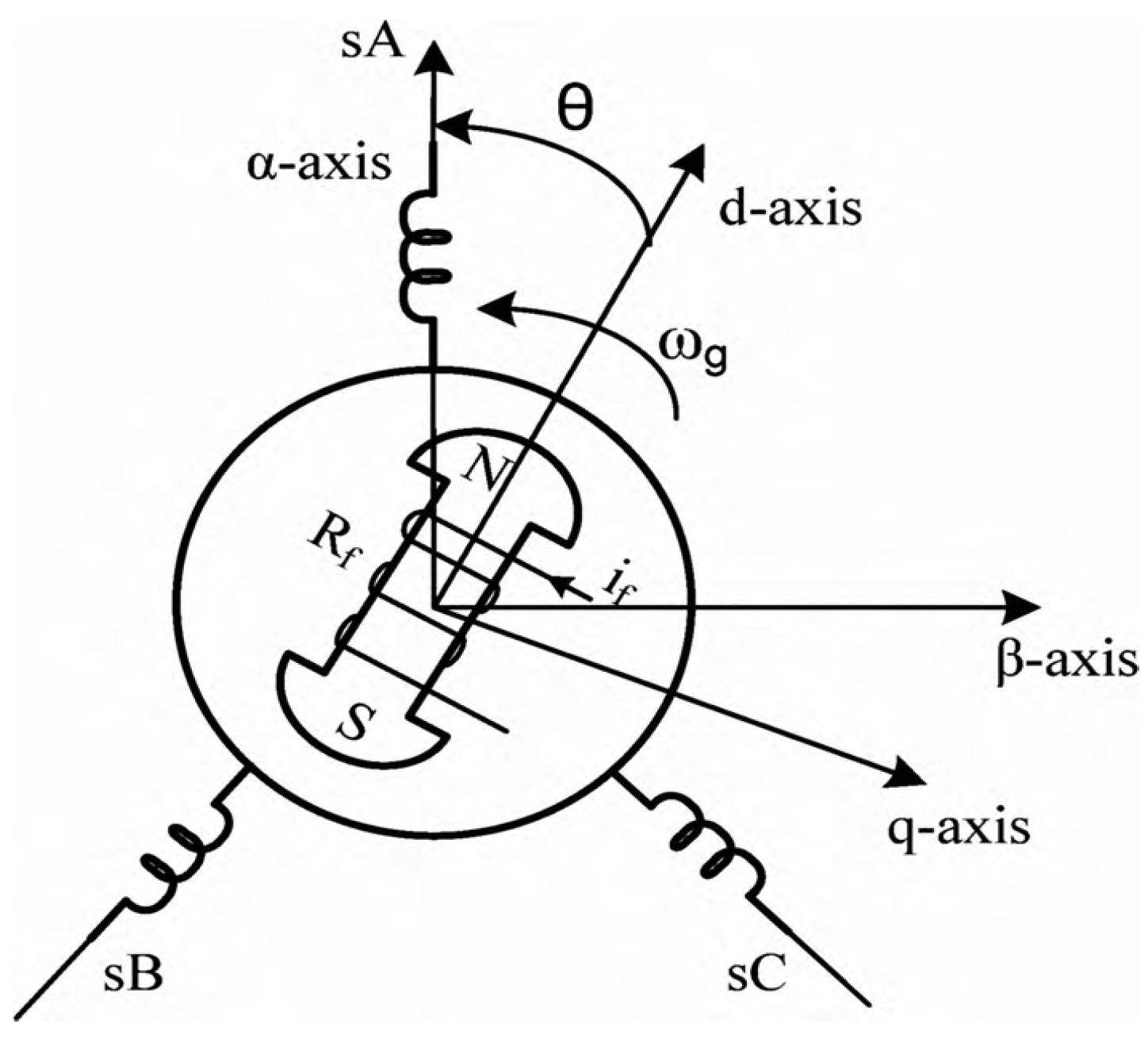
The PMSG dynamic model is achieved based on the two-phase synchronous reference model in which the q-axis is 90 degrees ahead of the d-axis due to the direction of rotation [31]. Synchronization is done with the two-phase d-q reference model and the three-phase abc model using the phase lock loop [31]. Figure 3 shows the d-q reference model used in the prominent pole synchronous machine (which is similar to the model used in the PMSG). In Figure 3, θ is the mechanical angle, the angle between the d-axis of the rotor and the axis of the stator. Usually, the mechanical model of PMSG is used to analyze the power system and converter based on the following hypotheses [32]: The stator windings are twisted at an air distance in the direction of mutual induction with the rotor. The effects of magnetic saturation and hysteresis can be ignored. The stator winding is symmetrical. The windings are not considered to be scattered, and their capacity is negligible as well, their resistance is considered constant (power losses are considered constant).
The mathematical model of PMSG is as follows [33]:
d i d d t = 1 L d s + L l s R a i d + ω e L q s + L l s i q + u d
d i q d t = 1 L q s + L l s R a i q + ω e L d s + L l s i q + K + u q  
Above, the d and q indices represent the physical parameters transmitted on a d-q basis. Ra is the stator resistor, L d and L q are the inductances of the generator on the d and q axes, respectively. K is also a permanent magnetic flux ( wb ). The electrical rotation speed of the generator ω e is also in units (rad/s). The electric speed is obtained from the following equation, where p is the number of poles of the generator.
ω e = p ω g  
To complete the mathematical model of PMSG, we need its mechanical model, which is determined by electromagnetic torque relationship as follows [34]:
T g = 1.5 p L d s L l s i d i q + i q K
To control the speed of PMSG, it is necessary to control the voltage or currents on its terminals. PWM converters are used for this purpose as well as for synchronizing the frequency and phase of the control current and the PMSG current. In these converters, using PMSG feedback signals, a pulse train is generated to activate the PWM converter [20]. Figure 4 shows an example of this type of synchronous machine speed control system. After comparing with the desired speed, the rotational speed of the machine enters a PI controller as a tracking error and the DC voltage associated with the desired speed is generated. This voltage is converted to a three-phase signal by a PWM converter fed by pulses generated based on feedback signals from the PMSG and finally applied to the machine terminals.
Another way to control the speed of a synchronous machine is to generate a ref current on a d-q basis using a PI controller. After the base change using the park transformation, the optimum current is given from PMSG to a PWM inverter along with a feedback current, in which the appropriate voltage and currents are generated synchronously on the PMSG terminals to track the desired speed.
Figure 5 shows an overview of the power converter system. In this model, the control block itself consists of several parts, which can be seen in the figure below.
In the Control Block, the error signal is obtained from the difference between the rotational speed of the generator ω g and the desired speed ω (g, ref).The optimal speed is the speed at which the generator receives maximum power from the turbine for a given wind speed [18]. The error signal is input to a PI block, and a ref signal is generated for the q-axis, i.e., i (q, ref). This reference signal provides a current ref signal in the three-phase domain by passing through a dq 2 abc converter in which the park transformation takes place [31]. The above relations are also true for currents. The angular velocity ω t is the same as the electric rotational angle of the rotor. The electric velocity is obtained by multiplying the number of poles by the mechanical rotational speed. The ref signal obtained in the three-phase domain ( i . e . , Iabc , ref ) , along with the feedback Iabc signal, is given from PMSG to PWM inverter, which adjusts the voltages v a and v b on the PMSG terminals so that the difference between   Iabc , ref and Iabc is zero. In this way, the rotational speed of the generator is set to the desired speed and the power received from the wind turbine will be maximized. However, in order to function properly, like other control methods, this control system requires sufficient accuracy in the parameters used in it. If the system model is not executed correctly, the control purpose will not be met. Comparative methods are usually used to deal with parametric uncertainty [35,36]. Sometimes parameter recognition mechanisms are used to compensate for the deviation between the parameters used in the control system and their actual value. In the following, we will deal with the subject of design and simulation. The equations and simulation data are used and modified from the reference [37].

4. Case Study and Simulation

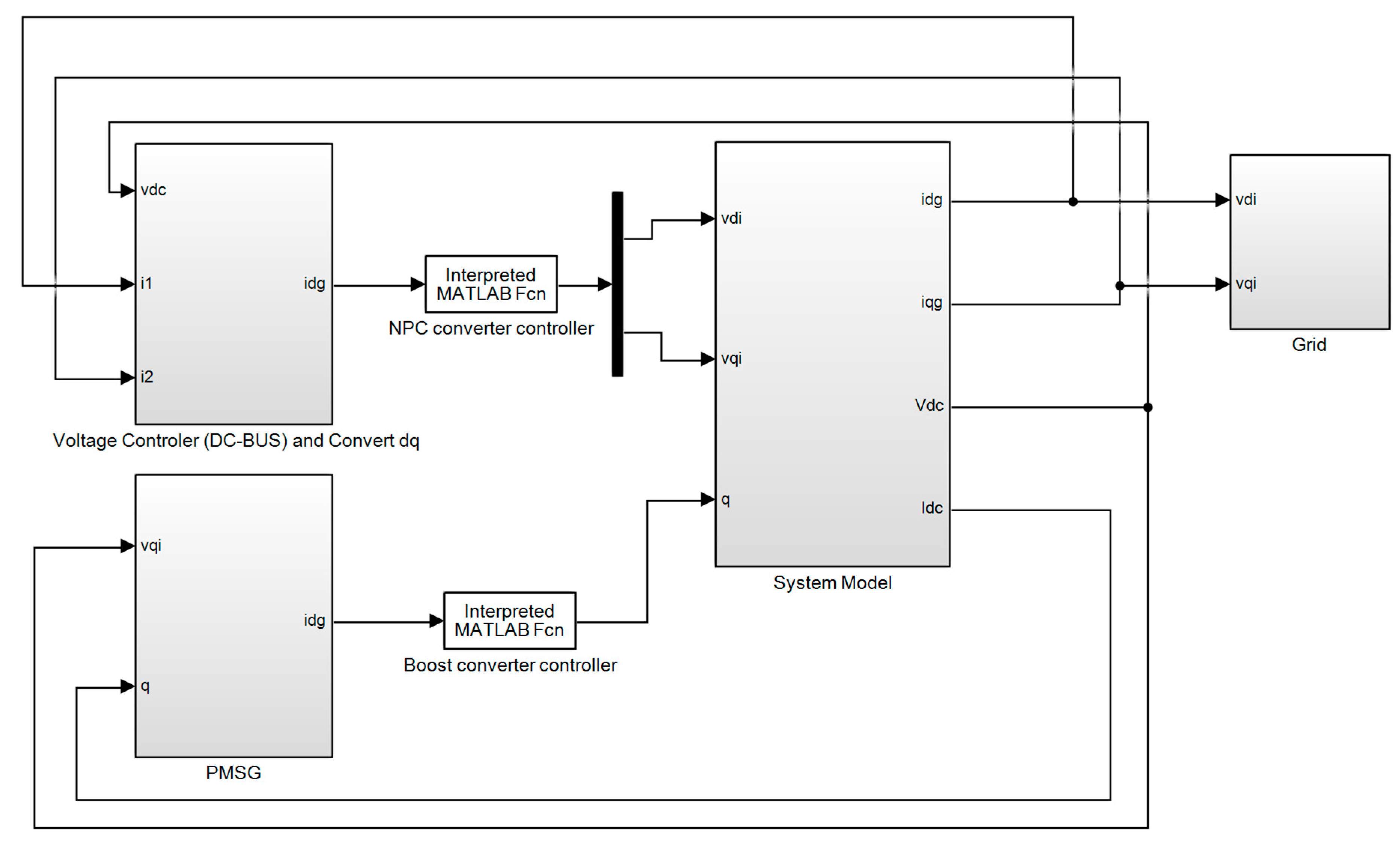
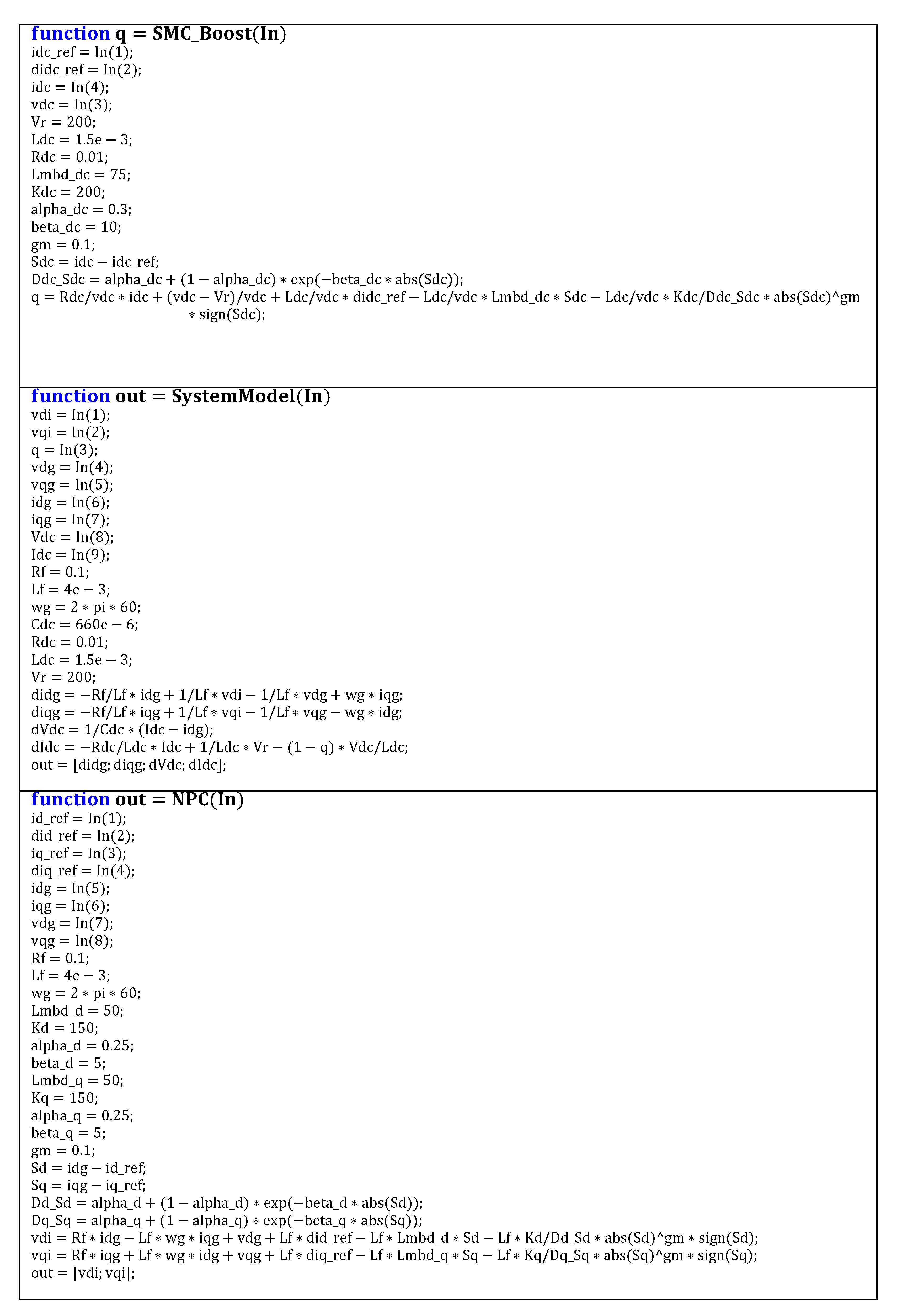
In Figure 6, the PMSG model is simulated using MATLAB with the proposed method, and the control subsystems are shown in Figure 7. In this model, NPC and a boost converter and grid are used, in addition to wind turbines and controllers. Low- to medium-voltage electrical energy is compared to similar controllers. In this model, the boost operation is relatively simple. A boost switching converter is one that increases the input-to-output voltage level while decreasing the current level. The boost converter is a class of switching power supplies. Figure 7 shows the model structures including SMC _ Boost , system model, and NPC.

5. Simulation Results

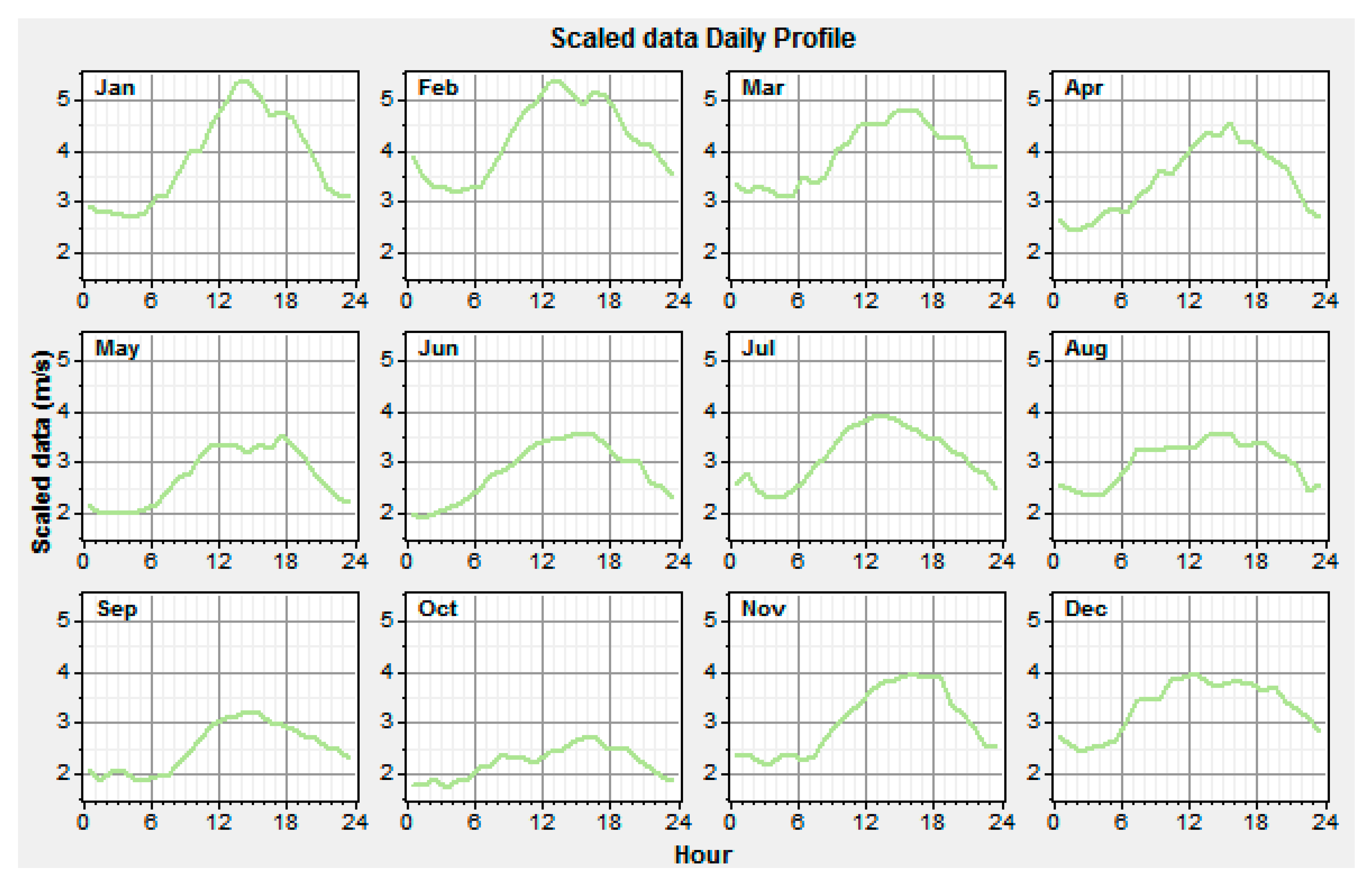
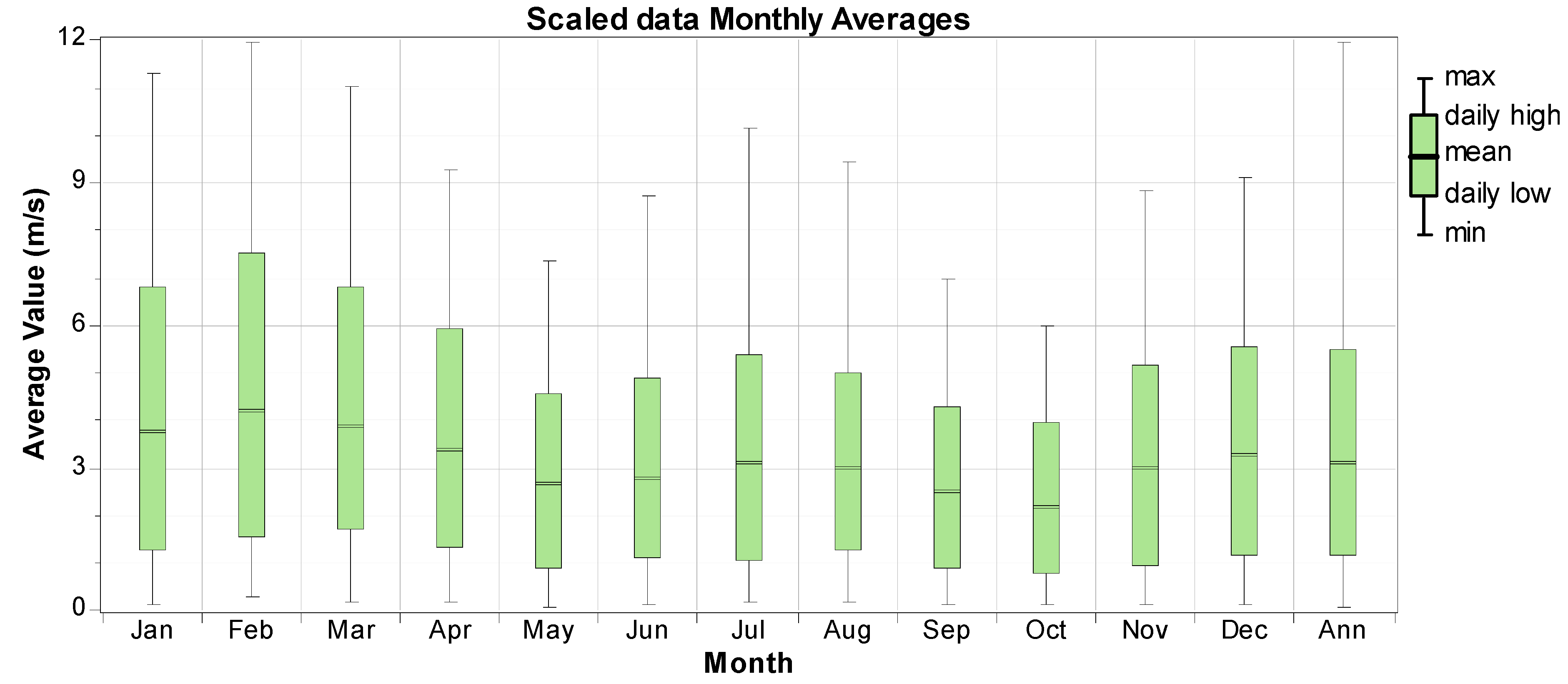
Now, we will review the presented model. We obtained the wind potential located in Turklan village (East Azerbaijan—Iran) using HOMER software (Figure 8 and Figure 9).
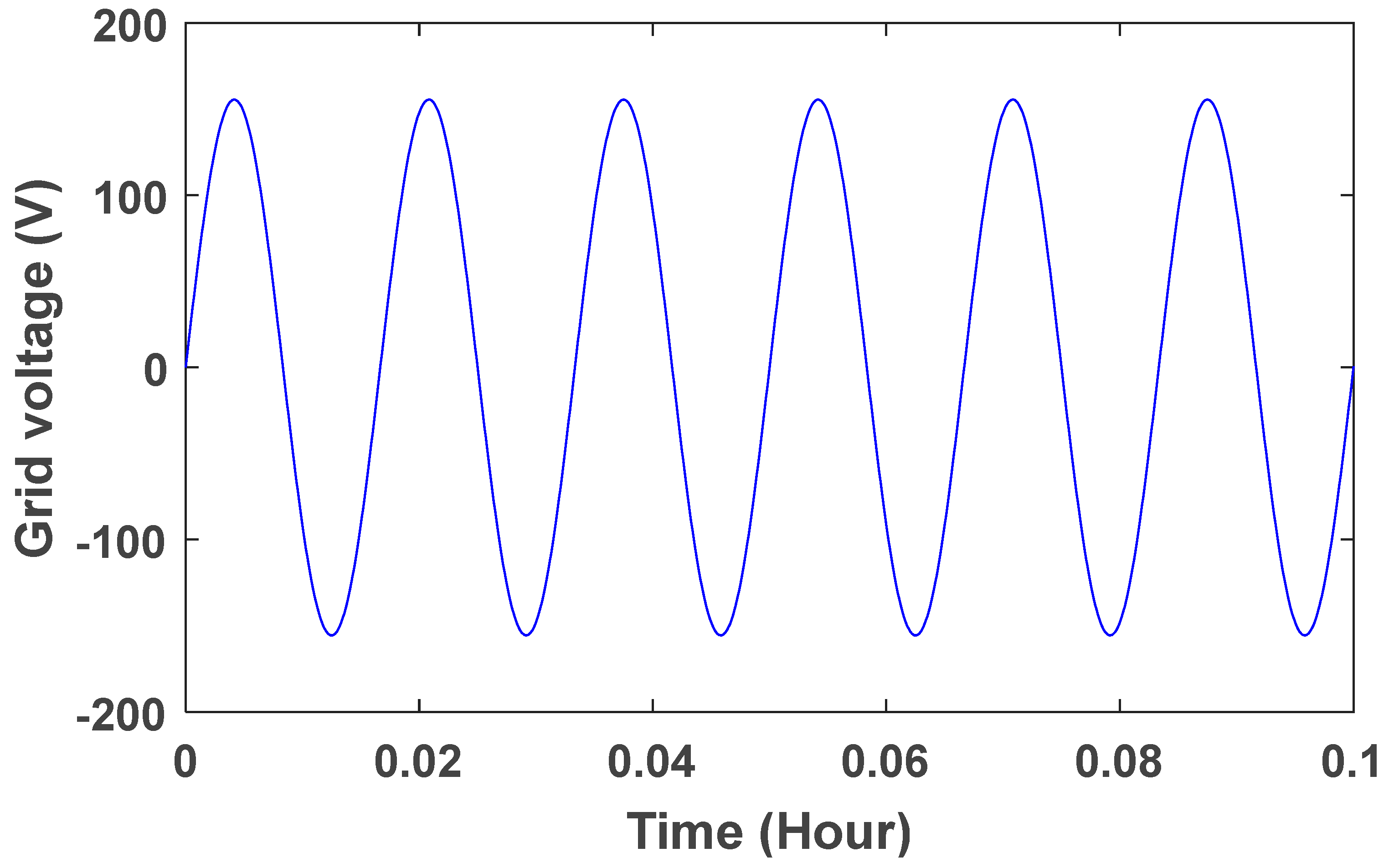
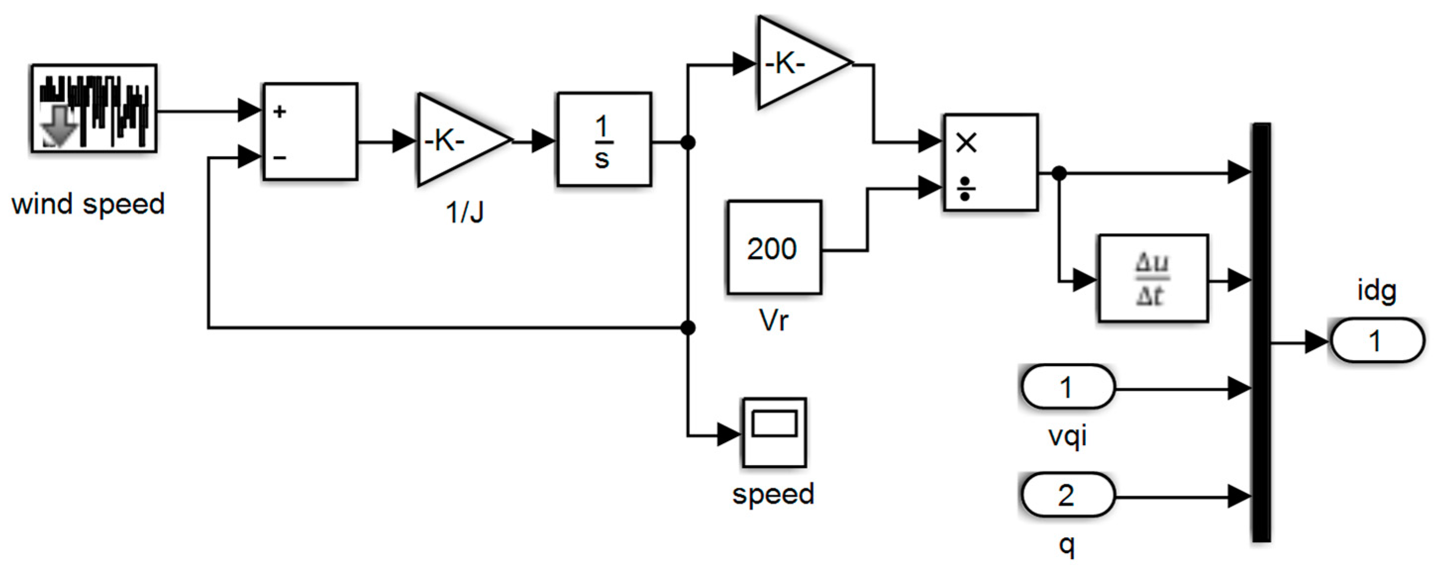
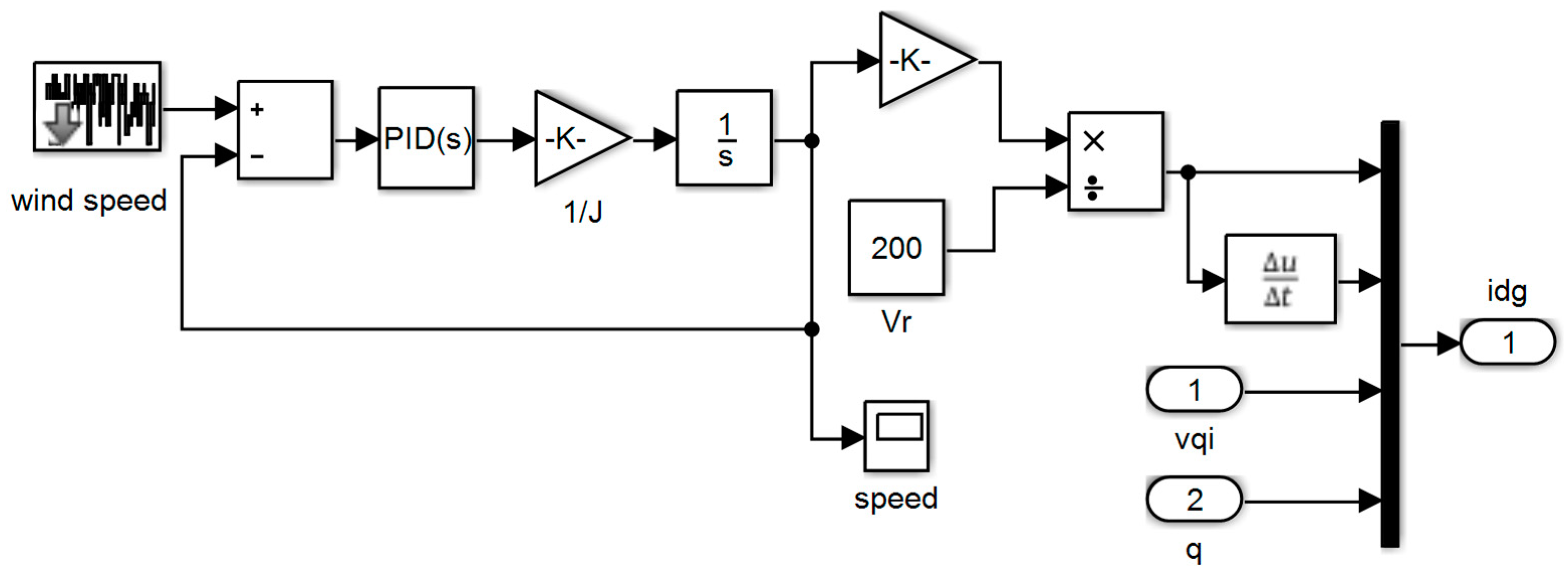
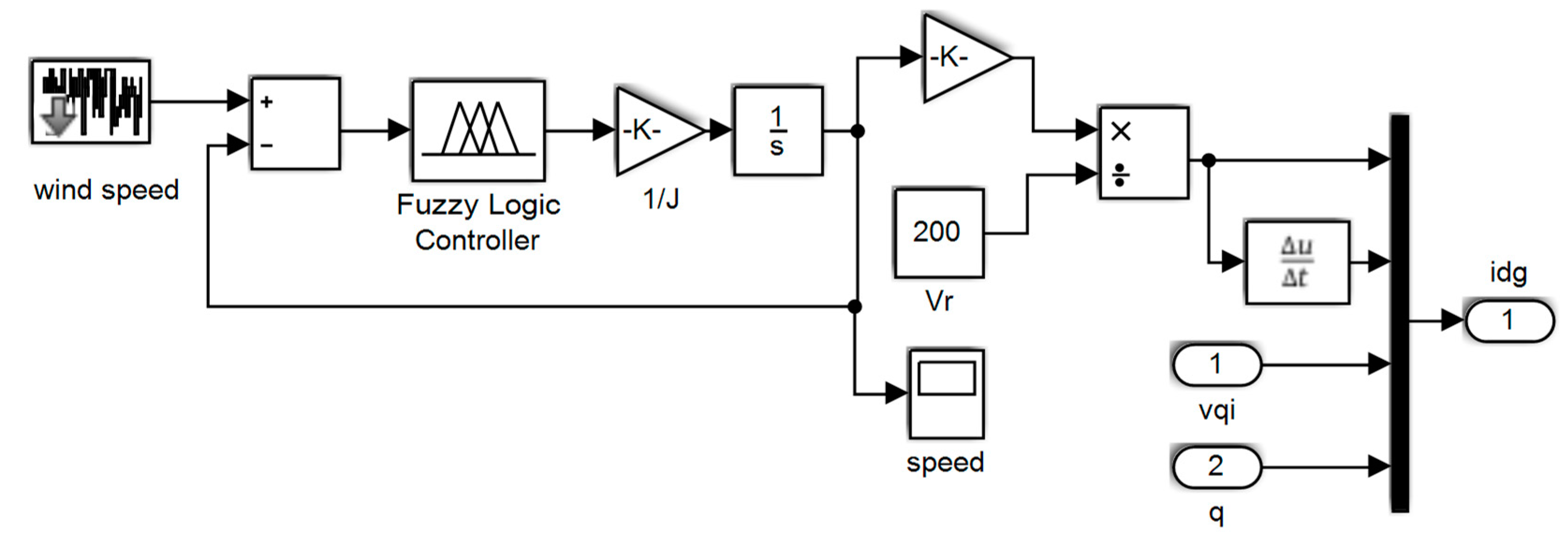
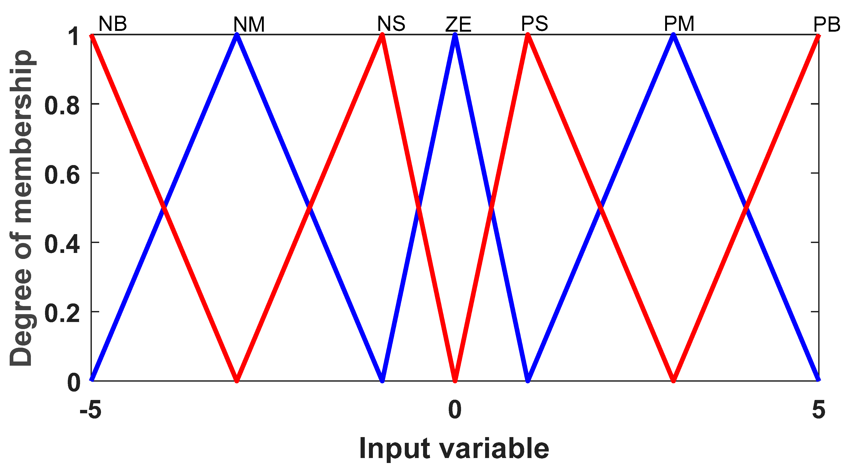
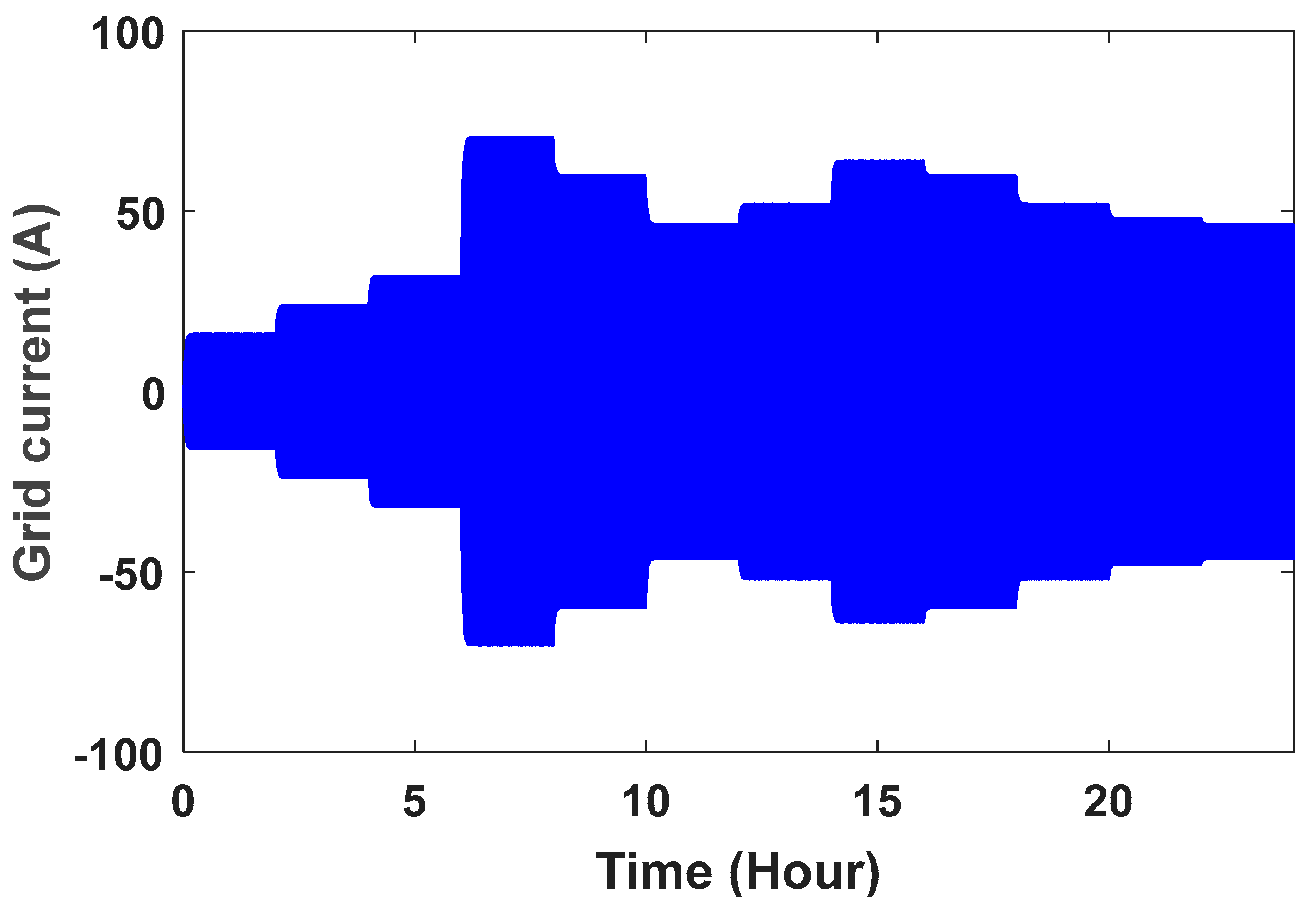
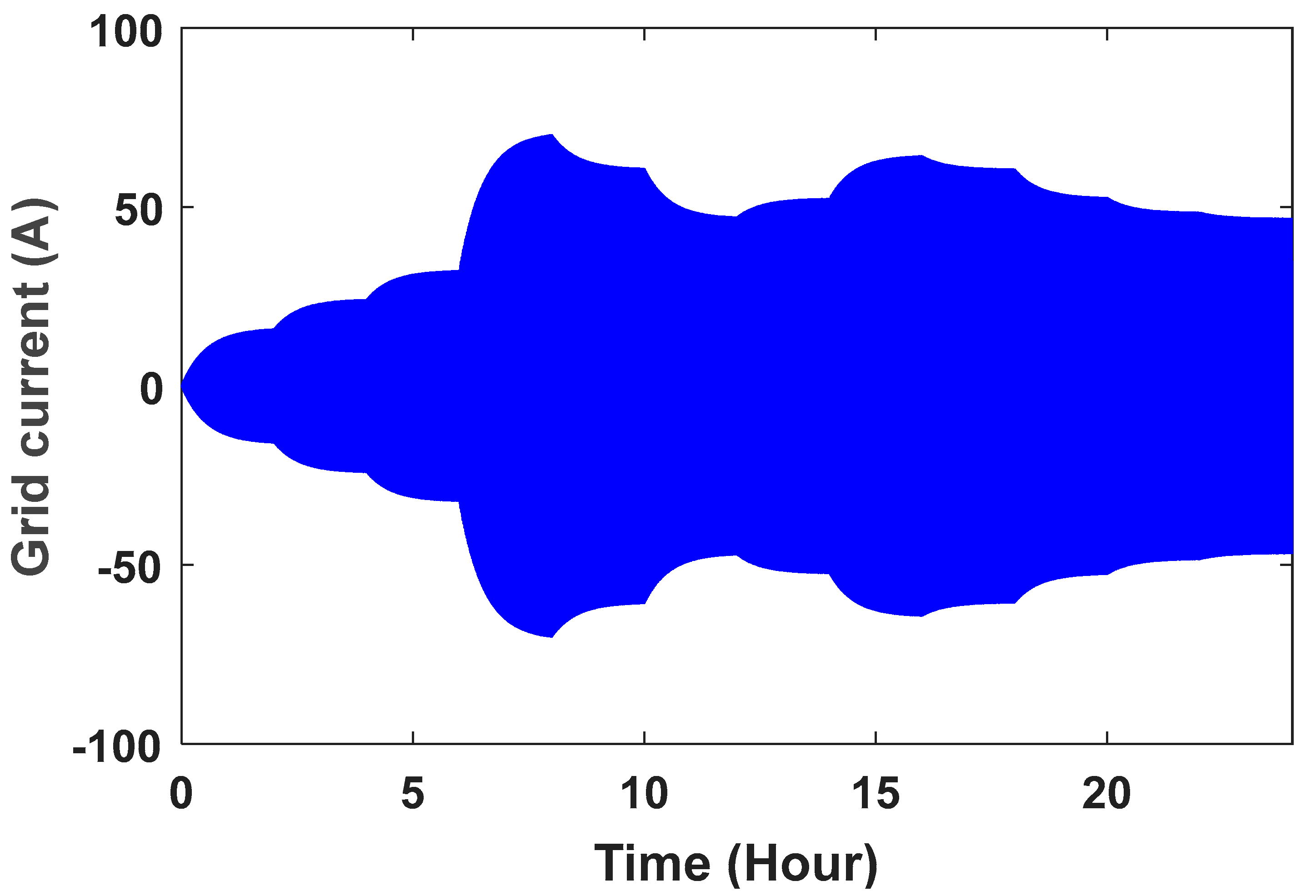
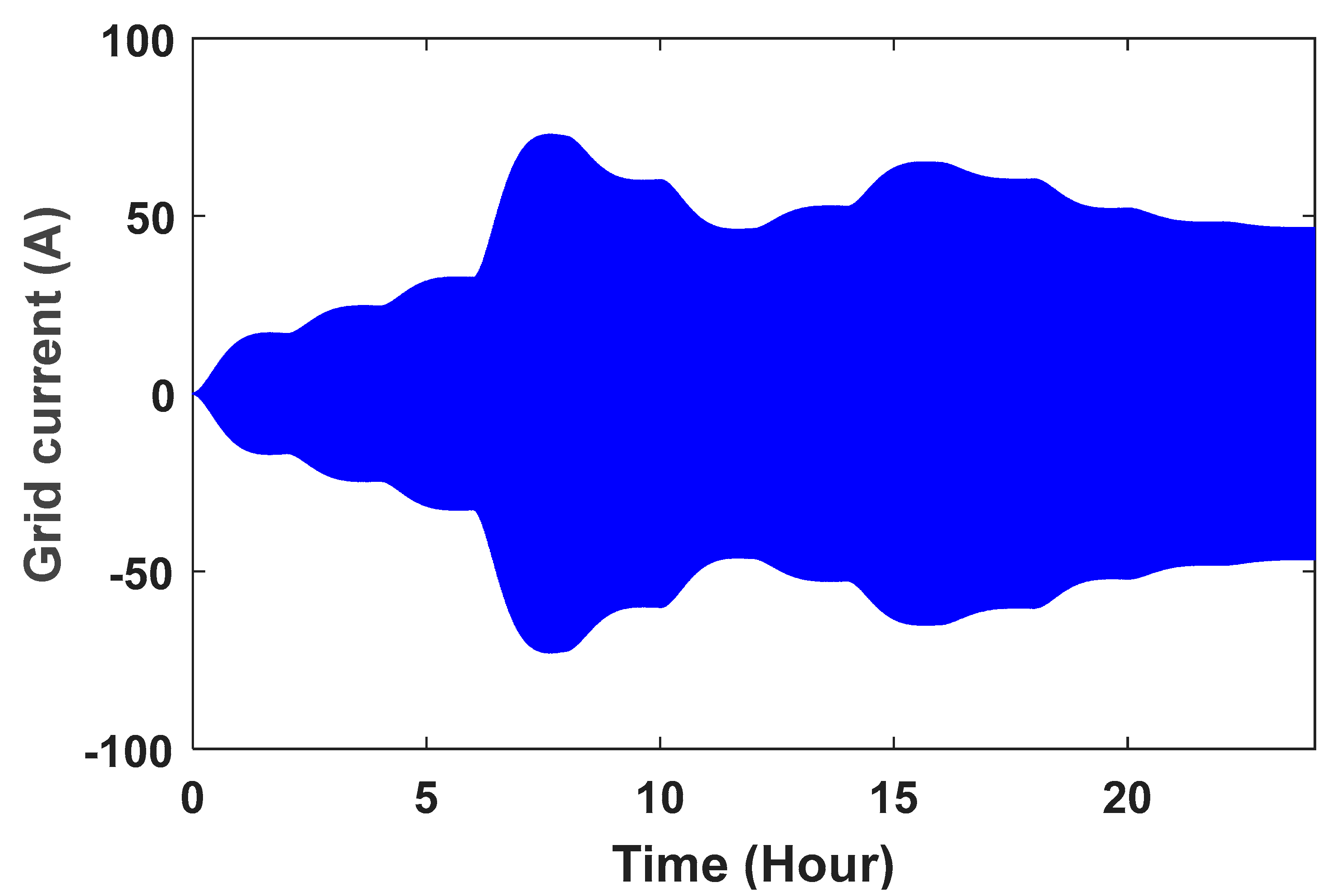
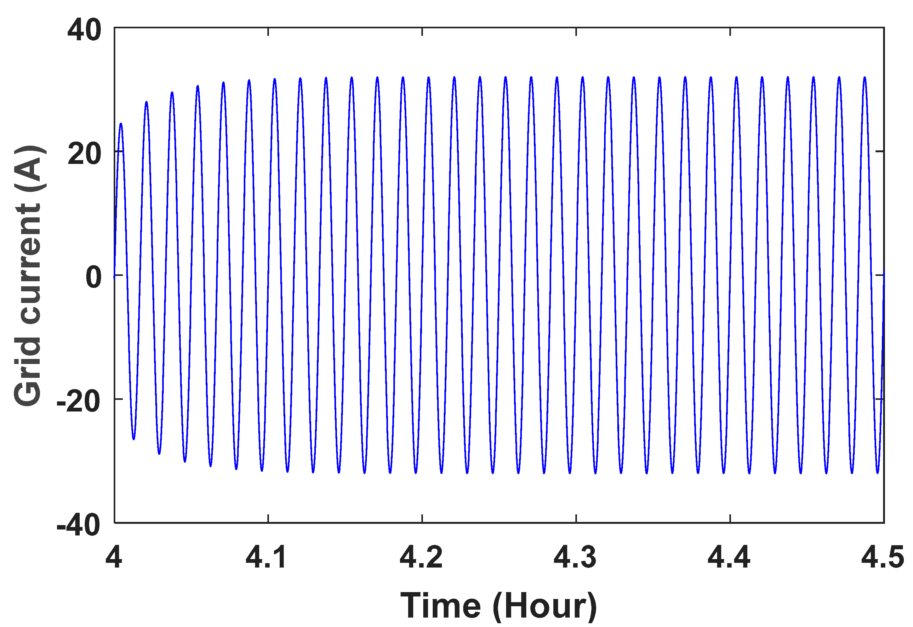
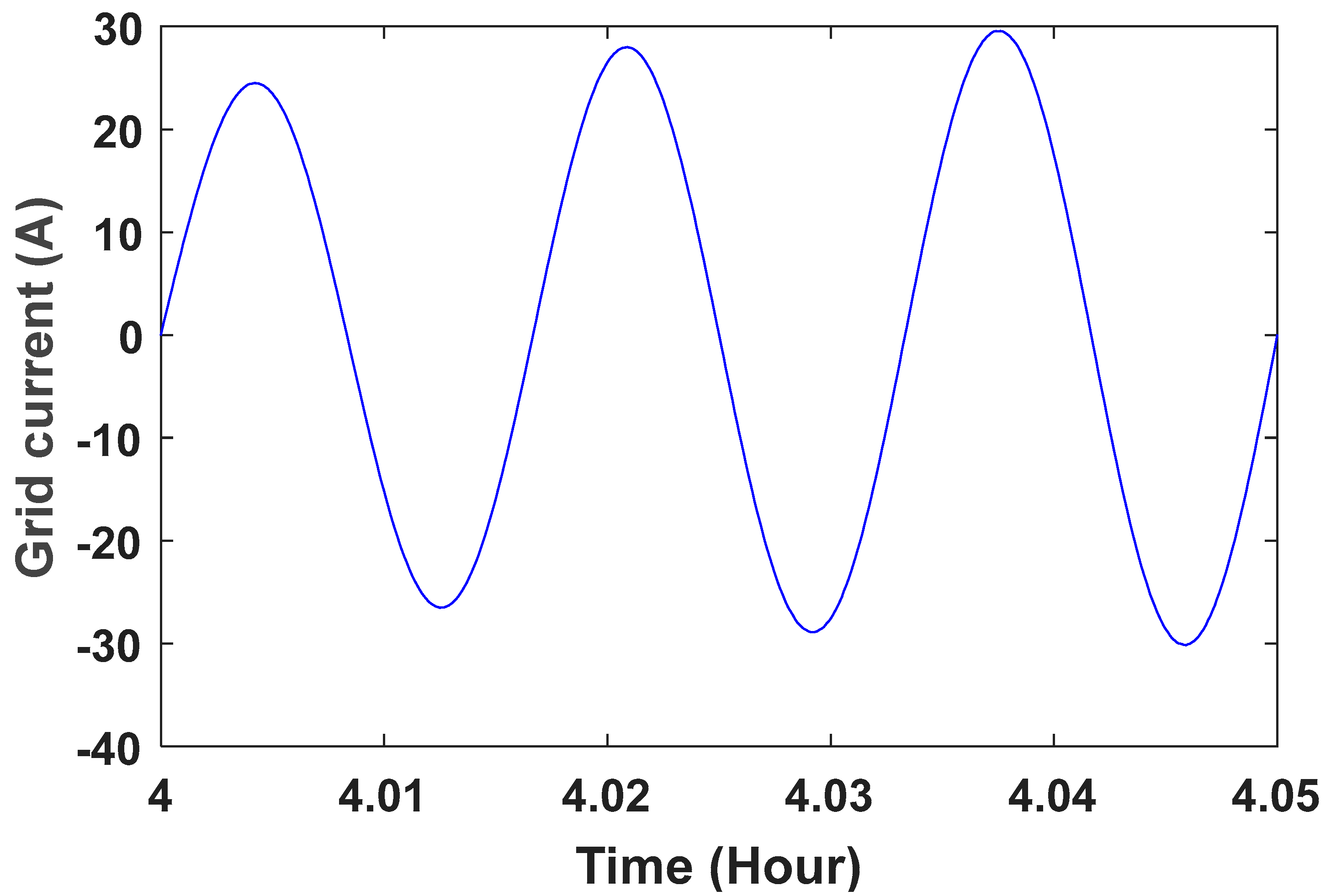
The grid voltage is shown in Figure 10. To better see the sine wave, the grid voltage wave in the time range of 0 t   0.1 is shown in Figure 11. The controller parameters are used to improve the dynamic response based on minimizing the controller performance criterion, which are based on the accuracy of the output in tracking the desired value. Table 1 presents the components of this controller and its advantages. Table 2 shows the value of the controller parameters. Figure 12, Figure 13, Figure 14 and Figure 15 show the speed control system in the PMSG. Table 3 and Table 4 show the fuzzy rules. The input and output membership degrees are shown in Figure 16 and Figure 17. Grid flow changes are shown in Figure 18 without a controller, in Figure 19 with a PI controller, with a PID controller in Figure 20, and in Figure 21 with a fuzzy controller. The sine wave of the grid current is better shown in Figure 22 and Figure 23 in the time range of 4 t     4.5 and again 4 t     4.05 .
When wind speed changes, a small change will be observed in the dc link voltage. The controller adjusts it very quickly. One of the important goals of the controller is the stability of the wind turbine. Studies show that controlling the switches in order to achieve the desired set voltage at the output is absolutely important and must be done properly. In Figure 24, it is clear that the voltage of the dc link without controller has changed significantly from 400 volts when the wind speed increases or decreases. At different times, the voltage reaches 408 and 397 V. In Figure 25, the voltage values are improved using controllers, and these values are between 400.6 and 399.8 with our PI control, 400.4 and 399.88 with PID control and 400.2 and 399.94 with fuzzy control. However, it has been observed that the DC link voltage variation always improves.
Conventional control theory uses an explicit mathematical (analytical) model of a controlled process and desired closed-loop behavior characteristics to design a controller. This approach will suffer if the model is difficult or (part of it) unknown or highly nonlinear. In these controllers, fuzzy sets are used to define the concept of qualitative values of inputs and outputs of the controller.
Fuzzy logic can capture the continuous nature of human decision-making processes and, as such, is a definite improvement over methods based on binary logic (which are widely used in industrial controllers).
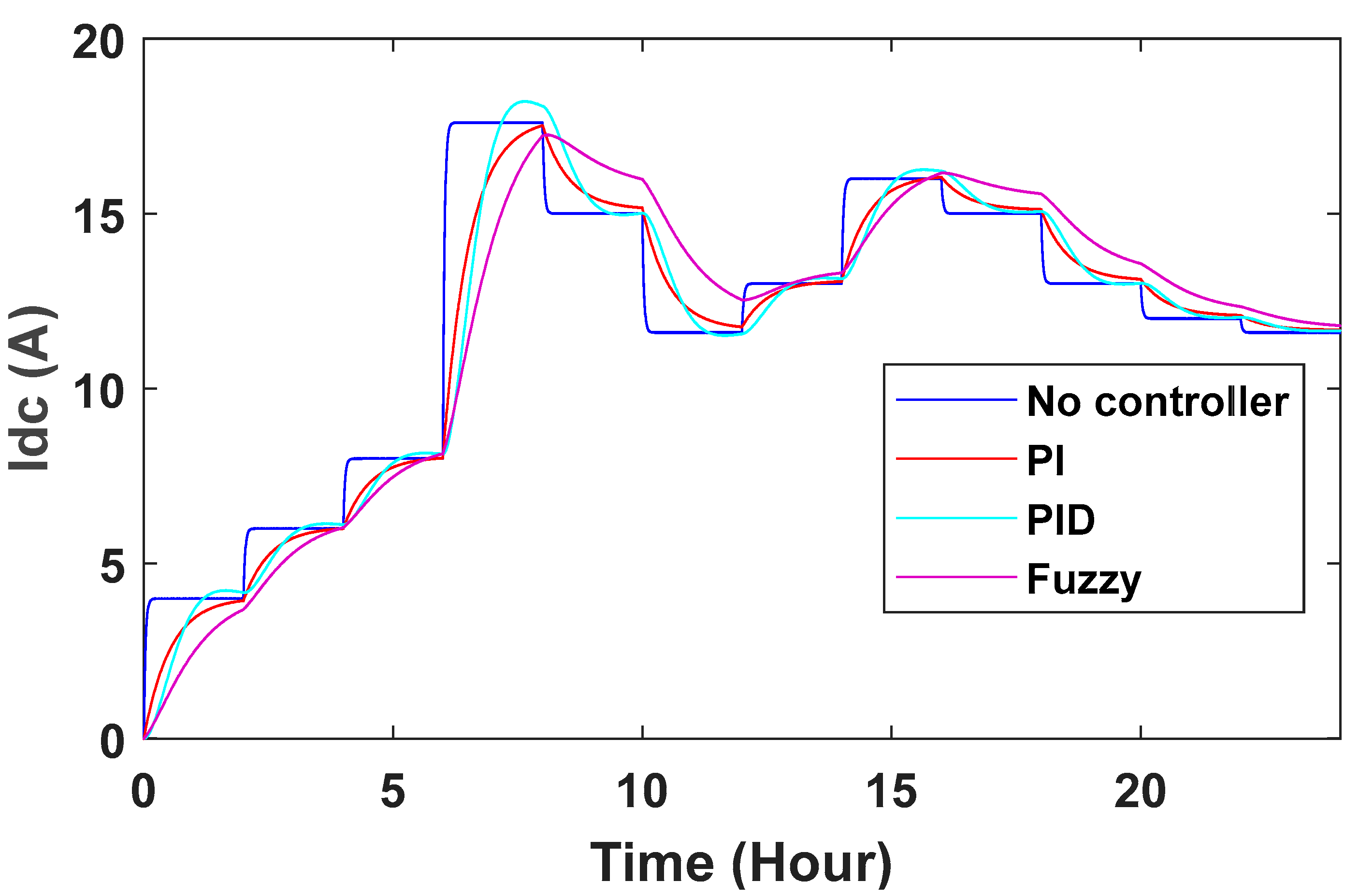
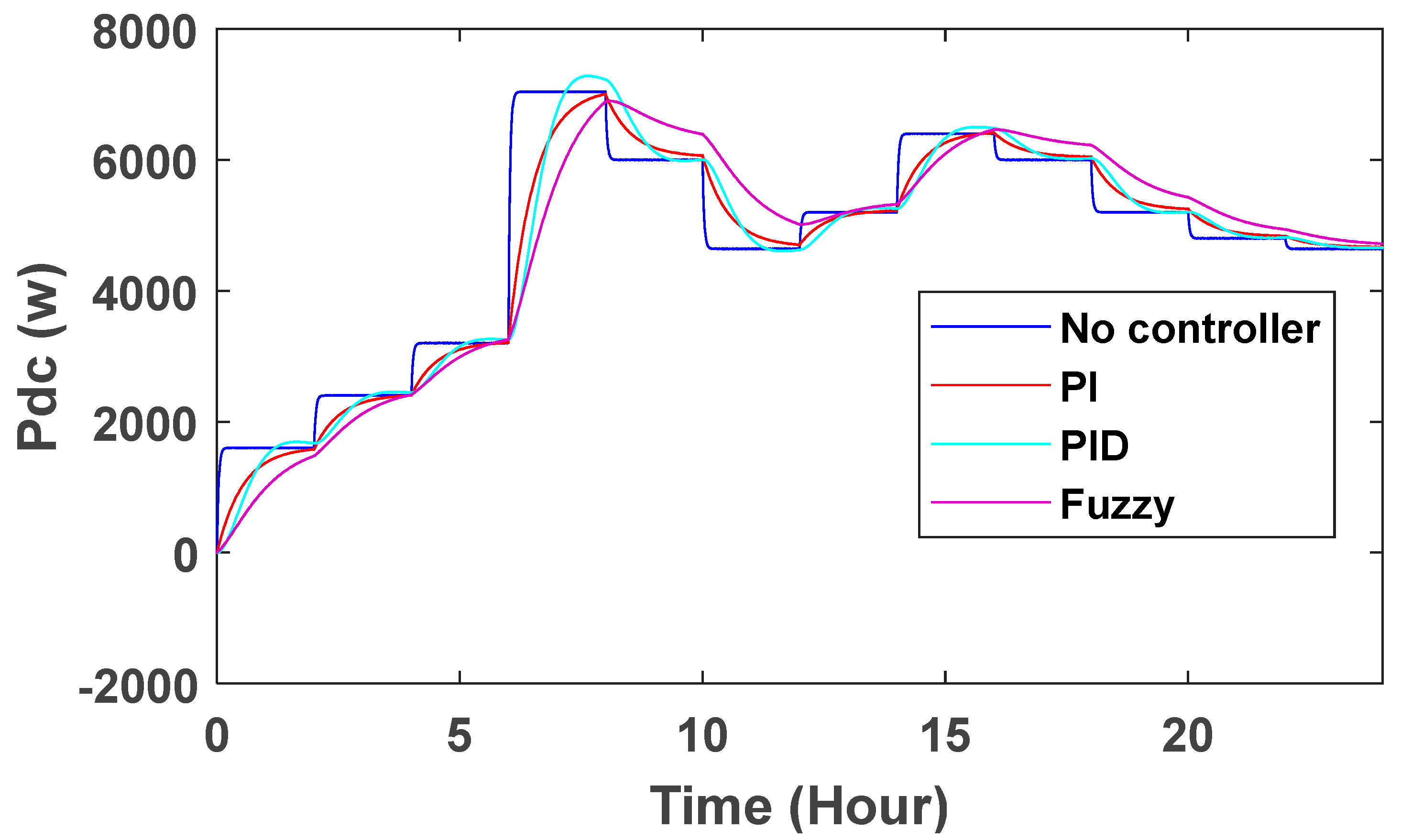
With the DC voltage link controller, changes can also be observed in DC current and DC power. Without the controller, the current and power curves are square, and at times when there are changes in wind speed, the values of current and power are also shown using PID, PI and fuzzy control (Figure 26 and Figure 27). In conventional power systems, it can be seen that there is a more stable state than the previous state with PI, PID and fuzzy controllers, but the stabilization time in this controller is longer. It also shows that the system with the controller has less deviation and is more stable than the system without the controller.
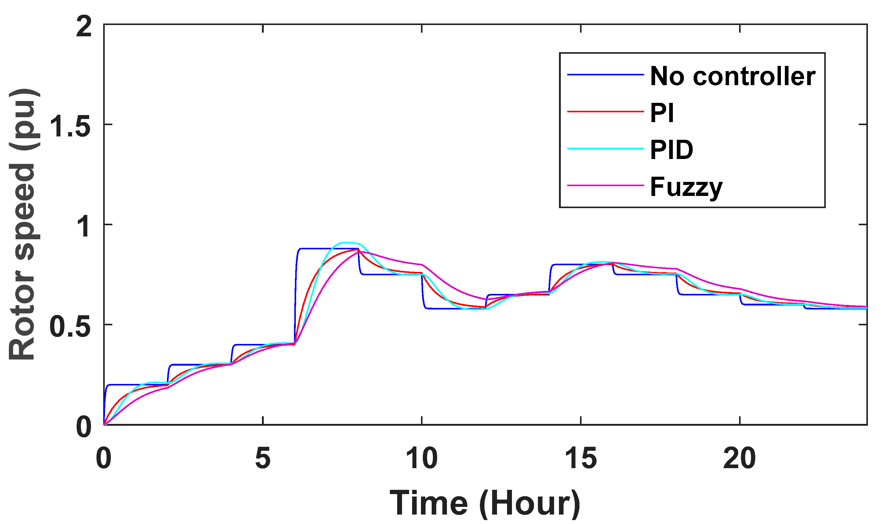
Changes in turbine rotor speed can also be seen in Figure 28. The speed of the turbine rotor is given feedback and the ref speed is reduced, and the difference between them is given to the controllers to get the desired speed of the turbine rotor.

6. Conclusions

In this research, the purpose of this article is to describe and compare the functions of different controllers in a permanent magnet synchronous wind turbine generator. Control methods were used in PMSG wind turbines connected to the grid. To control the DC voltage link and turbine rotor speed at high wind speeds, PI, PID and fuzzy-based controllers with a neutral-point-clamped and boost converter were proposed. As can be seen from the results, DC link voltage changes without controllers are beyond normal, which must be adjusted by a controller. It was also shown that the system with the controller has less deviation and is more stable than the system without the controller. Voltage values are improved using controllers. The DC link voltage increased from 408 V, which reached 400.6 with PI control, 400.4 with PID and 400.2 with fuzzy control. Along with these controllers, we used the neutral-point-clamp method at the same time. According to the results obtained from the simulation and comparison, it can be said that the use of a fuzzy controller in the structure of the speed control system has a better performance than other control.

A Look at Future Works

Use of neural network to improve results
Using uncertainty in the presented model

Author Contributions

Conceptualization, J.Y.; Methodology, F.Z.; Software, L.T.; Validation, L.T.; Formal analysis, F.Z.; Investigation, F.Z. and N.S.; Resources, L.T., J.Y. and N.S.; Data curation, L.T. and N.S.; Writing—review & editing, F.Z. and J.Y.; Funding acquisition, J.Y. All authors have read and agreed to the published version of the manuscript.

Funding

This work was supported by the National Research Foundation of Korea (NRF) grant funded by the Korea government (MSIT) (NRF-2021R1F1A1063640).

Data Availability Statement

The data used in this study are reported in the paper’s figures and tables.

Conflicts of Interest

The authors declare no conflict of interest.

References

  1. Bhukya, J.; Mahajan, V. Optimization of damping controller for PSS and SSSC to improve stability of interconnected system with DFIG based wind farm. Int. J. Electr. Power Energy Syst. 2019, 108, 314–335. [Google Scholar] [CrossRef]
  2. Ali, M.A.S.; Mehmood, K.K.; Baloch, S.; Kim, C.H. Modified rotor-side converter control design for improving the LVRT capability of a DFIG-based WECS. Electr. Power Syst. Res. 2020, 186, 106403. [Google Scholar] [CrossRef]
  3. Mokhtari, M.; Aminifar, F. Toward Wide-Area Oscillation Control through Doubly-Fed Induction Generator Wind Farms. IEEE Trans. Power Syst. 2014, 29, 2985–2992. [Google Scholar] [CrossRef]
  4. Zhu, R.; Chen, Z.; Wu, X.; Deng, F. Virtual damping flux-based LVRT control for DFIG-based wind turbine. IEEE Trans. Energy Convers. 2015, 30, 714–725. [Google Scholar] [CrossRef]
  5. Liu, J.; Yang, Z.; Yu, J.; Huang, J.; Li, W. Coordinated control parameter setting of DFIG wind farms with virtual inertia control. Int. J. Electr. Power Energy Syst. 2020, 122, 106167. [Google Scholar] [CrossRef]
  6. Huang, S.; Wang, J.; Huang, C.; Zhou, L.; Xiong, L.; Liu, J.; Li, P. A fixed-time fractional-order sliding mode control strategy for power quality enhancement of PMSG wind turbine. Int. J. Electr. Power Energy Syst. 2022, 134, 107354. [Google Scholar] [CrossRef]
  7. Yu, J.; Li, J.; Hu, W.; Wang, H.; Huang, Q.; Che, Z. Small-signal modeling of wind farm with direct-drive PMSG using the component connection method. Energy Rep. 2021, 7, 334–342. [Google Scholar] [CrossRef]
  8. Dali, A.; Abdelmalek, S.; Bakdi, A.; Bettayeb, M. A new robust control scheme: Application for MPP tracking of a PMSG-based variable-speed wind turbine. Renew. Energy 2021, 172, 1021–1034. [Google Scholar] [CrossRef]
  9. Qais, M.H.; Hasanien, H.M.; Alghuwainem, S. A novel LMSRE-based adaptive PI control scheme for grid-integrated PMSG-based variable-speed wind turbine. Electr. Power Energy Syst. 2021, 125, 106505. [Google Scholar] [CrossRef]
  10. Trongtorkarn, M.; Theppaya, T.; Techato, K.; Luengchavanon, M.; Kasagepongsarn, C. Relationship between Starting Torque and Thermal Behaviour for a Permanent Magnet Synchronous Generator (PMSG) Applied with, Vertical Axis Wind Turbine (VAWT). Sustainability 2021, 13, 9151. [Google Scholar] [CrossRef]
  11. Feng, S.; Wang, K.; Lei, J.; Tang, Y. nfluences of DC bus voltage dynamics in modulation algorithm on power oscillations in PMSG-based wind farms. Int. J. Electr. Power Energy Syst. 2021, 124, 2021. [Google Scholar] [CrossRef]
  12. Yaramasu, V.; Dekka, A.; Durán, M.J.; Kouro, S.; Wu, B. PMSG-based wind energy conversion systems: Survey on power converters and controls. IET Electr. Power Appl. 2017, 11, 956–968. [Google Scholar] [CrossRef]
  13. Kord, H.; Barakati, S.M. Design an adaptive sliding mode controller for an advanced hybrid energy storage system in a wind dominated RAPS system based on PMSG. Sustain. Energy Grids Netw. 2020, 21, 100310. [Google Scholar] [CrossRef]
  14. Tai, L.; Lin, M.; Wang, J.; Hou, C. Synchronous Control Strategy with Input Voltage Feedforward for a Four-Switch Buck-Boost Converter Used in a Variable-Speed PMSG Energy Storage System. Electronics 2021, 10, 2375. [Google Scholar] [CrossRef]
  15. Nguyena, H.T.; Al-Sumaiti, A.S.; Vu, V.-P.; Al-Durra, A.; Do, T.D. Optimal power tracking of PMSG based wind energy conversion systems by constrained direct control with fast convergence rates. Int. J. Electr. Power Energy Syst. 2020, 118, 105807. [Google Scholar] [CrossRef]
  16. Matayoshi, H.; Howlader, A.M.; Datta, M.; Senjyu, T. Control strategy of PMSG based wind energy conversion system under strong wind conditions. Energy Sustain. Dev. 2018, 45, 211–218. [Google Scholar] [CrossRef]
  17. Soufyane, B.; Abdelhamid, R.; Smail, Z.; Elhafyani, M.L.; El Hajjaji, A. Fully Robust Sensorless Control of Direct-Drive PMSG Wind Turbine Feeding a Water Pumping System. IFAC-Pap. 2020, 53, 12797–12802. [Google Scholar] [CrossRef]
  18. Urtasun, A.; Sanchis, P.; Martín, I.S.; López, J.; Marroyo, L. Modeling of small wind turbines based on PMSG with diode bridge for sensorless maximum power tracking. Renew. Energy 2013, 55, 138–149. [Google Scholar] [CrossRef]
  19. Kim, K.-H.; Jeung, Y.-C.; Lee, D.-C.; Kim, H.-G. Robust control of PMSG wind turbine systems with back-to-back PWM converters. In Proceedings of the The 2nd International Symposium on Power Electronics for Distributed Generation Systems, Hefei, China, 16–18 June 2010. [Google Scholar] [CrossRef]
  20. Wang, C.N.; Le, X.K.; Lin, W.C. Modelling and Simulation of Autonomous Control PMSG Wind Turbine. In Proceedings of the 2014 International Symposium on Computer, Consumer and Control, Taichung, Taiwan, 10–12 June 2014; Volume 27. [Google Scholar] [CrossRef]
  21. Li, S.; Haskew, T.A.; Swatloski, R.P.; Gathings, W. Optimal and Direct-Current Vector Control of Direct-Driven PMSG Wind Turbines. IEEE Trans. Power Electron. 2012, 27, 2325–2337. [Google Scholar] [CrossRef]
  22. Maaruf, M.; Shafiullah, M.; Al-Awami, A.T.; Al-Ismail, F.S. Adaptive Nonsingular Fast Terminal Sliding Mode Control for Maximum Power Point Tracking of a WECS-PMSG. Sustainability 2021, 13, 13427. [Google Scholar] [CrossRef]
  23. Alayi, R.; Zishan, F.; Mohkam, M.; Hoseinzadeh, S.; Memon, S.; Garcia, D.A. A for microgrids integrated to the national grid using sustainable energy distribution configuration back-to-back converters in a renewable power system. Electronics 2021, 10, 1826. [Google Scholar] [CrossRef]
  24. Mayilsamy, G.; Palanimuthu, K.; Venkateswaran, R.; Antonysamy, R.P.; Lee, S.R.; Song, D.; Joo, Y.H. A Review of State Estimation Techniques for Grid-Connected PMSG-Based Wind Turbine Systems. Energies 2023, 16, 634. [Google Scholar] [CrossRef]
  25. Kuppusamy, S.; Joo, Y.H. Stabilization of PMSG-based wind turbine systems with sampling information: Dynamic delay partition method. Int. J. Electr. Power Energy Syst. 2023, 149, 109023. [Google Scholar] [CrossRef]
  26. Salime, H.; Bossoufi, B.; El Mourabit, Y.; Motahhir, S. Robust Nonlinear Adaptive Control for Power Quality Enhancement of PMSG Wind Turbine: Processor-in-the-Loop Verification. Sustainability 2023, 15, 939. [Google Scholar] [CrossRef]
  27. Guo, F.; Yu, J.; Ni, Q.; Zhang, Z.; Meng, J.; Wang, Y. Grid-forming control strategy for PMSG wind turbines connected to the low-frequency AC transmission system. Energy Rep. 2023, 9, 1464–1472. [Google Scholar] [CrossRef]
  28. Berrueta, A.; Sacristán, J.; López, J.; Rodríguez, J.L.; Ursúa, A.; Sanchis, P. Inclusion of a Supercapacitor Energy Storage System in DFIG and full-converter PMSG Wind Turbines for Inertia Emulation. IEEE Trans. Ind. Appl. 2023. [Google Scholar] [CrossRef]
  29. Raouf, A.; Tawfiq, K.B.; Eldin, E.T.; Youssef, H.; El-Kholy, E.E. Wind Energy Conversion Systems Based on a Synchronous Generator: Comparative Review of Control Methods and Performance. Energies 2023, 16, 2147. [Google Scholar] [CrossRef]
  30. Mousa, H.H.; Youssef, A.-R.; Mohamed, E.E. Optimal power extraction control schemes for five-phase PMSG based wind generation systems. Eng. Sci. Technol. Int. J. 2020, 23, 144–155. [Google Scholar] [CrossRef]
  31. Cirrincione, M.; Pucci, M.; Vitale, G. Neural MPPT of Variable-Pitch Wind Generators With Induction Machines in a Wide Wind Speed Range. IEEE Trans. Ind. Appl. 2013, 49, 942–953. [Google Scholar] [CrossRef]
  32. Ullah, N.R. Wind Power—Added Value for Network Operation; Chalmers University of Technology: Gothenburg, Sweden, 2008; ISBN 978-91-7385-198-5. [Google Scholar]
  33. Ullah, N.R.; Thiringer, T.; Karlsson, D. Temporary Primary Frequency Control Support by Variable Speed Wind Turbines Potential and Applications. IEEE Trans. Power Syst. 2008, 23, 601–612. [Google Scholar] [CrossRef]
  34. Shen, B.; Mwinyiwiwa, B.; Zhang, Y.; Ooi, B.-T. Sensorless maximum power point tracking of wind by DFIG using rotor position phase lock loop (PLL). IEEE Trans. Power Electron. 2009, 24, 942–951. [Google Scholar] [CrossRef]
  35. Mansouri, S.; Zishan, F.; Montoya, O.D.; Azimizadeh, M.; Giral-Ramírez, D.A. Using an intelligent method for microgrid generation and operation planning while considering load uncertainty. Results Eng. 2023, 17, 100978. [Google Scholar] [CrossRef]
  36. Zishan, F.; Mansouri, S.; Abdollahpour, F.; Grisales-Noreña, L.F.; Montoya, O.D. Allocation of Renewable Energy Resources in Distribution Systems while Considering the Uncertainty of Wind and Solar Resources via the Multi-Objective Salp Swarm Algorithm. Energies 2023, 16, 474. [Google Scholar] [CrossRef]
  37. Mozayan, S.M.; Saad, M.; Vahedi, H.; Fortin-Blanchette, H.; Soltani, M. Sliding Mode Control of PMSG Wind Turbine Based on Enhanced Exponential Reaching Law. IEEE Trans. Ind. Electron. 2016, 63, 6148–6159. [Google Scholar] [CrossRef]
  38. Alayi, R.; Zishan, F.; Seyednouri, S.R.; Kumar, R.; Ahmadi, M.H.; Sharifpur, M. Optimal load frequency control of island microgrids via a PID controller in the presence of wind turbine and PV. Sustainability 2021, 13, 10728. [Google Scholar] [CrossRef]
  39. Zishan, F.; Akbari, E.; Montoya, O.D.; Giral-Ramírez, D.A.; Molina-Cabrera, A. Efficient PID Control Design for Frequency Regulation in an Independent Microgrid Based on the Hybrid PSO-GSA Algorithm. Electronics 2022, 11, 3886. [Google Scholar] [CrossRef]
  40. Zishan, F.; Montoya, O.D.; Giral-Ramírez, D.A. New Design and Study of the Transient State and Maximum Power Point Tracking of Solid Oxide Fuel Cells Using Fuzzy Control. Energies 2023, 16, 2572. [Google Scholar] [CrossRef]
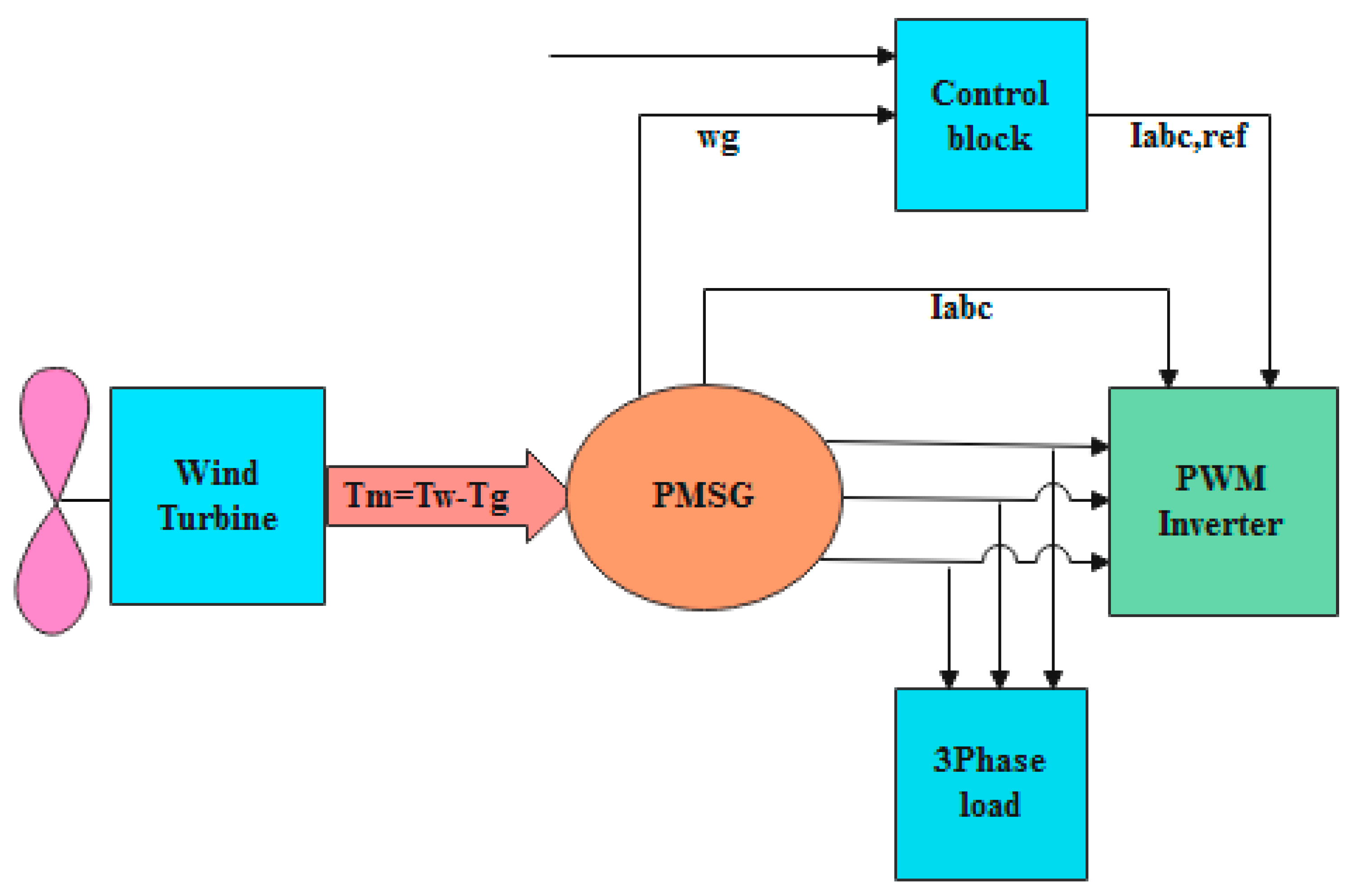
Figure 1. Wind energy conversion system with PMSG.
Energies 16 04108 g001
Figure 2. Single-line diagram of PMSG wind turbine.
Energies 16 04108 g002
Figure 3. The d-q and α-β axes for the prominent pole synchronous machine.
Energies 16 04108 g003
Figure 4. PMSG speed control system with ref voltage.
Energies 16 04108 g004
Figure 5. Speed control system in PMSG receives maximum power.
Energies 16 04108 g005
Figure 6. Simulated design model.
Energies 16 04108 g006
Figure 7. Pseudo code of MC-Boost, System Model, and NPC equations and data.
Energies 16 04108 g007
Figure 8. Wind profile in different months, Turklan village (East Azerbaijan—Iran).
Energies 16 04108 g008
Figure 9. Wind speed in different months, Turklan village (East Azerbaijan—Iran).
Energies 16 04108 g009
Figure 10. Grid voltage wave.
Energies 16 04108 g010
Figure 11. Grid voltage wave (between 0 and 0.1).
Energies 16 04108 g011
Figure 12. Speed control system without controller.
Energies 16 04108 g012
Figure 13. Speed control system with PI controller.
Energies 16 04108 g013
Figure 14. Speed control system with PID controller.
Energies 16 04108 g014
Figure 15. Speed control system with fuzzy controller.
Energies 16 04108 g015
Figure 16. Input membership function.
Energies 16 04108 g016
Figure 17. Output membership function.
Energies 16 04108 g017
Figure 18. Grid flow without controller.
Energies 16 04108 g018
Figure 19. Controller grid flow with PI controller.
Energies 16 04108 g019
Figure 20. Grid flow with PID controller.
Energies 16 04108 g020
Figure 21. Grid flow with fuzzy controller.
Energies 16 04108 g021
Figure 22. Grid current wave in the time range of 4 ≤ t ≤ 4.5.
Energies 16 04108 g022
Figure 23. Grid current wave in the time range of 4 ≤ t ≤ 4.05.
Energies 16 04108 g023
Figure 24. DC link voltage changes without controllers.
Energies 16 04108 g024
Figure 25. DC link voltage changes with PI and PID controllers.
Energies 16 04108 g025
Figure 26. DC current changes.
Energies 16 04108 g026
Figure 27. DC power changes.
Energies 16 04108 g027
Figure 28. Turbine rotor speed changes.
Energies 16 04108 g028
Table 1. Controller parameters [38,39].
ControllerValueToo LargeToo Small
PIncreased response speedDecreased stabilityLarge deviation (permanent error)
IReduced unstable errorDecreased stabilitySlower return to set point
DIncreased stability (decreased oscillation range)Increased stability of reinforcing perturbationsLack of full access to benefits
Table 2. The value of controller parameters.
The Type of ControllerPID
PI0.0610.00093-
PID0.0610.00093−0.016
Table 3. Fuzzy variable language [40].
PBPMPSZENSNMNBLanguage of Fuzzy Variables
Big positiveMedium positiveSmall positiveZeroSmall negativeAverage negativeBig negative
Table 4. Rule base for fuzzy controller [40].
Number of Rule1234567
NBNMNSZEPSPMPB
1NBZEZEZENBNBNBNB
2NMZEZEZENMNMNMNM
3NSNSZEZENSNSNSNS
4ZENMNSZEZEZEPSPM
5PSPMPSPSPSPSZEPS
6PMPMPMPMPMPMZEZE
7PBPBPBPBPBPBZEZE
Disclaimer/Publisher’s Note: The statements, opinions and data contained in all publications are solely those of the individual author(s) and contributor(s) and not of MDPI and/or the editor(s). MDPI and/or the editor(s) disclaim responsibility for any injury to people or property resulting from any ideas, methods, instructions or products referred to in the content.