Article

Modeling of Electrical Systems for Uninterrupted Operation of Drives in Case of Short-Term Distortions in the Supply Networks

1
NPK Promir Limited Liability Company, Storozhevaya Street, 26, Bilding 1, 111020 Moscow, Russia
2
Institute of Digital Technologies and Modeling in Construction, Moscow State University of Civil Engineering, Yaroslavskoye Shosse, 26, 129337 Moscow, Russia
*
Author to whom correspondence should be addressed.
Energies 2023, 16(10), 4184; https://doi.org/10.3390/en16104184
Submission received: 17 April 2023 / Revised: 15 May 2023 / Accepted: 17 May 2023 / Published: 18 May 2023

Abstract

:
The article considers the problem of increasing the stability of an electrical system with running synchronous and asynchronous electric motors, which are electrically connected through an intra-factory network and for which the operating modes affect the stability of the entire load. A method is proposed for studying electrical systems with an electric motor load to assess the effect of short-term power supply interruptions (voltage dips) in supply networks on the dynamic stability of synchronous and asynchronous drives. The influence of considering operating synchronous and asynchronous electric motors on transient processes and levels of residual voltages of sections was studied. It was found that to ensure the stability of the drives, to avoid shutdowns in case of various types of short circuits, it is desirable to use an automatic reserve input with a response time of less than 12 ms. A device for the instantaneous activation of a reserve is proposed, providing a response time of 9 ms and a total switching time to a reserve input within 17 ÷ 65 ms. The results of experiments and calculations according to the author’s developed programs are presented, confirming the possibility of the uninterrupted operation of technical electric systems consumers. The requirements for such automation devices are determined.

1. Introduction

A reduction in losses caused by the shutdown of high-voltage motors, cutoff of drives with voltage up to 1 kV, due to short-term distortions in the supply networks, is important for the electrical complexes of enterprises [1,2,3,4,5]. The number of short-term power outages (SPOs) is going up due to growing climatic environmental impacts.
The complexes and power-supply schemes of chemical, petrochemical, mining and metallurgical enterprises are constantly evolving, and new capacities and production facilities are expected to be commissioned, for which it is important to assess the transient operating modes of electric motors of technical electrical systems (TESs) with expected changes in switchgear circuits [1,6,7,8,9,10,11] with power supply system voltages of 110(220) kV. Enterprise schemes have (a) two or more exterior sources (PS1, PS2), (b) own generation (usually with a voltage of 6, 10 kV), (c) large number of transformer substations (TS) and switchgears (SG), (d) an extensive industrial electrical network, (e) a high (more than 50%) share and power of the electric motor load (with diversity by types), and (f) closed network circuits, which require special methods for studying the stability of electrical systems [1,12,13].
Power supply distortions in the supply system (in the form of short circuits of various types) cause shutdowns of electric motors and mechanisms and, as a result, financial losses in production caused by the underdelivery of products as well as a loss of customer loyalty [3,4,5,14,15,16]. There are special consumers, such as extruders, pumps, fans, refrigeration units with adjustable speed drive variable (ASD), machine tools with program control and electromagnetic valves [2,3,4,5,8,15,16,17], which are turned off during voltage dips of 10 ÷ 20 ms in duration and depth from 15%.
To ensure the uninterrupted operation of such consumers, classic power supply schemes for switchgear or substations (SS) are used from two supply transformers (powered from 110/220 kV lines) together with the use of automation in case of the emergency cutoff of one of the inputs and the power switching to a backup source [1,6,8,18,19,20]. A way to ensure the self-starting of critical consumers powered by two independent sources is the introduction of the automatic transfer of the reserve (ATS) with the minimum possible switching time [1,21,22,23]. Conventional ATS devices with SPOs in the power system determine the emergency mode by the level of residual voltage (usually at the level 0.4 U n o m ), which leads to an increase in the total time of switching to the backup source and causes the electric motors to stop [1,8,16,17,18,19,21].
An increase in the reaction time to an emergency mode caused by a short circuit (SC) leads to the fact that at the moment of switching to a backup source, transient processes occur that are comparable to the processes during electric motors starting, which are accompanied by hydraulic shocks, pipeline ruptures, and equipment damage [8,17,19,24]. If there are motors in the switchgear sections or substations, the voltage on the buses of the switchgear sections does not decrease at the first moment after the short circuit but is maintained due to the electromotive force (EMF) of the motors at such a level that the operation of the ATS will be prohibited for 0.05 ÷ 0.12 s [6,8,19,20,21]. Then, during the operation of conventional ATS, the technological processes, such as the functioning of electric motors of pumps and compressors, are interrupted [2,7,9,14,15,19,20].
The classic switchgear scheme with two sections of busbars and an ATS between them was introduced during the construction of a diesel fuel and kerosene production plant by an American company in the Republic of Tatarstan in 1995. However, the technological process was often disrupted by short circuits (SCs) and SPOs in the supply networks with a voltage of 110.35 kV due to the stopping of dozens of drives of the Petrofac installation. In 2009, it was proposed to launch an thyristor reserve input device (TRID), when a power thyristor with a voltage of 6 (10) kV was connected in parallel to a sectional switch [25], whose reaction time was less than 5 ms; however, the automation of the device was waiting for the input switch to turn off at the 6 kV switchgear. The total reaction time of the thyristor reserve input device (TRID) increased to 0.15 ÷ 0.3 s, depending on the type of short circuit, included load, and the location of the SPOs. The introduction of the TRID at SG-6 kV showed that it does not keep the main equipment of the Petrofac unit (gas and oxygen compressors, pumps for supplying various reagents, fans, refrigeration units) operational, its operation depends on the power of the switched-on load, the device does not always adequately respond to emergency mode, and it is unable to work several times with repeated SPOs. The shutdown of the technological process was accompanied by economic loss because reaching the required purity of the produced fuel occurred after tens of hours, or even several days. Therefore, the task of ensuring the resulting stability of electric motors required new ways to solve it [8,9,10,11,12,13,14,20,24,26].
All of the above arguments emphasize the relevance of the problem to be solved and the introduction of promising technologies in the work of electrical complexes. For such TES, it is important to ensure the uninterrupted operation of electric motors with converters in the supply circuit [1,2,5,10,15,26] with SPOs in the supply networks caused by short circuits of various types. When developing technical solutions for the smooth work of drives, we propose to take into account the influence of the type and place of the short circuit; the number and types of operating synchronous (SM) and asynchronous (AM) motors at different stages of transient processes [7,8,9,12,13,27], which is the novelty of the presented results.

2. Materials and Methods

2.1. Mathematical Model and Method for Studying an Electrical System

The refinery provided with the Petrofac process unit receives energy from two substations of the power system via overhead lines (VOL) with a voltage of 35 kV (the first with a total length of 13.89 = 2.98 + 10.91 km; the second with a length of 5.76 km). The substations are powered by 110 kV overhead lines. The power supply of the Petrofac installation (sections 13 and 14 in Figure 1) is carried out via 6 kV cable lines from the substation SS-152 with transformers with a capacity of 2 × 6.3 MVA (Figure 1). The electrical circuit includes an intra-factory electrical network, motors and other loads ( P e t c + j Q e t c ) connected by switches (Figure 1) [4].
The network elements are presented in the form of branches (there are 62 of them) with complex resistances Z B = R B + j X B ( R B , X B is an active, reactive resistance of the branch), which are calculated according to the passport data of the network elements taken from the catalogs. The Petrofac plant includes gas and oxygen compressors, pumps for supplying various reagents, fans, refrigerating units with a power of 70 to 250 kW, voltage of 380 V (18 main asynchronous drives are connected to sections 13 and 14 of Figure 1 AM1-AM18).
Auxiliary electrical equipment and the load of the production and amenity facilities ( S d o m e s t i c ) as well as the central laboratory ( S l a b ) are run by Sections 15 and 16 (Figure 1). The TES includes 3 SMs with capacities of 320, 320 and 800 kW (SM1, SM2, and SM3; see nodes 43, 44, and 110). The load factor of asynchronous motor is 65–75%.
The basis of the mathematical model of the considered power supply system (Figure 1) includes 90 differential equations describing 25 asynchronous and 3 synchronous motors, 62 branches (including two power supplies), 20 load sections and 57 switches.
To introduce promising technologies into the work of electrical complexes, it is necessary to study transient modes for normal and repair circuits of TES [6,8,9,13]. The proposed method is based on the performance of the computational studies of TES from the power supply system to end users with a voltage of 380 V. The method will require solving a system of hundreds of differential equations at each integration step [8,9,13,28]. Only this method will allow to determine reliable parameters for selecting the ATS complex when changing the configuration of the electrical network in order to ensure the continuity of technological processes during short-term disturbances lasting 20 ÷ 500 ms as well as the power supply both in the supply power system and in the internal plant network.
The error of the mathematical model of the whole system depends on the accuracy of the parameters of SM, AM and generators of stations, the degree of description of transient processes in motors and generators by differential equations, methods for accounting for changes in electromagnetic and electromechanical processes at the stages of coasting during a short circuit, coasting after short-circuit elimination and self-starting of the electric motor load [6,7,8,9,10,11,13,26,27].
For electrical complexes, the proposed mathematical model and method take into account all synchronous and asynchronous electric motors with voltages of 6 and 10 kV, as well as powerful AM with a voltage of 0.4 kV (Figure 1). Each SM or synchronous generator is described by its own system of four differential equations of the first and second orders, namely
d δ d t = ω 0 s ,
T J d 2 δ d t 2 = T J d s d t = M M X M C D ;
where δ is the angle that characterizes the position of the rotor with respect to the synchronously rotating axis of the EMF vector of the system; ω 0 is synchronous speed equal to ω 0 = 2 π f 0 = 314 1/s; s is the motor rotor slip; T J is electromechanical time constant of the engine–mechanism unit; and M M X and M C D are the moment of resistance of the mechanism and the electromagnetic moment of the SM.
  • Electromagnetic transient processes along the longitudinal axis
    T d T d d 2 E q d t 2 + T d + T d d E q d t + E q = T d + T d X d X d X d d U q d t + + X d X d X d U q + X d X d E q , n U f + T σ 1 d d U f d t ;
    where T d , T d are the time constants of the transient and super transient processes; E d , E q E q , E d are the longitudinal and transverse components of the synchronous (supertransient) EMF along the d , q axes; X d , X q are synchronous inductive resistances along the d and q axes; X d , X q are supertransient inductive resistances along the d and q axes; U q is the voltage across the transverse winding of the SM stator; U f is the excitation winding voltage; T σ 1 d is the time constant determined by the leakage inductance of the equivalent damper circuit; X d is the transient resistance of the SM along the d axis, taking into account the influence of the damper circuit; and E q , n is the synchronous EMF of the motor in the nominal mode. A synchronous motor is represented by a classical SM equivalent circuit along the longitudinal ( d ) and transverse ( q ) axes [6].
  • Electromagnetic transients along the transverse axis
    T 1 q d E d d t + E d = X q X q X q U d .
The supertransient resistances along the longitudinal ( X d ) and transverse ( X q ) axes, the time constants of the transient and supertransient processes along the longitudinal ( T d , T d ) and transverse ( T 1 q ) axes with a short-circuited stator winding are not constant values; therefore, in our model, they are recalculated when there are the motor slip changes during transition processes.
Synchronous generators in combined TES with their own generation are modeled by a system of differential Equations (1)–(4) but in the power output mode (with a negative load factor that does not depend on the rotor speed). The first synchronous generator in such systems, according to the proposed method, is a balancing (special) node, designated by the number “1”.
The transient processes of TES with AM based on the theory of two reactions use differential equations describing the electromagnetic transient processes of AM [6,8]:
T J d ω d t = M E M M M X ;
T 2 d E B d t + E B = U X 1 X X 1 2 T 2 s E B 2 ;
T 2 d E C d t + E C = 0 ,
M M X = M 0 + K z M 0 ω / ω u s t z cos φ n η ; M E M = P / ω 0 ,
where T J is the electromechanical time constant of the engine–mechanism unit; ω is the angular frequency of rotation of the motor rotor; M M X and M E M are the moment of resistance of the mechanism and the electromagnetic moment; T 2 is the time constant of the rotor winding with a short-circuited stator winding; supertransient EMF ( E ) , consisting of free ( E C ) and forced ( E B ) components, is the rotor speed in steady mode, defined as
ω e s t = 1 s n ,
where s n is the nominal slip of the AM; P is the active power consumed by the motor from the network; ω 0 is the synchronous voltage frequency at the motor outputs; M 0 is the initial moment of resistance of the mechanism at ω = 0; z is the exponent characterizing the dependence of the moment of resistance of the mechanism on the rotational speed; and K z is the engine load factor, defined as
K z = P P n ,
where P n is the rated power of the AM.
The AM mode, connected to the electrical network with voltage U, is characterized by the following parameters: rotor speed ( ω ) and supertransient EMF ( E ), consisting of free ( E C ) and forced ( E B ) components. Through the main parameters of the AM mode, all other parameters of the mode are determined by algebraic expressions.
When calculating the parameters of engines and generators, their changes as a function of the angular frequency of rotation [6,8] are taken into account, which significantly increases the accuracy of transient calculations. The method allows for the TES to take into account the joint/autonomous operation of combined sources (including its own generation), the presence of closed circuits and a large number of integrated load nodes.
For TES with combined power sources (several sources of an external power system E C and several generators of their own generation E G , Figure 2), we calculate the parameters of the steady mode by solving the nodal voltage equations:
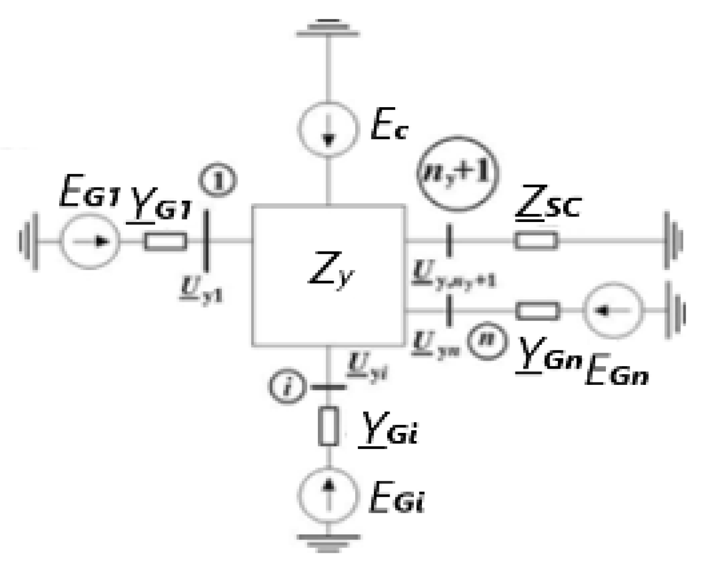
  • For the first level (from the supply system to the load nodes, Figure 2):
    U y ̲ = E C ̲ Z y ̲ · J y ̲ ;
    where U y ̲ is the underscore symbol that means a vector quantity.
  • For the second level (from load nodes to SM and AM outputs):
    J y ̲ = J p r ̲ + J C D ̲ + J A D ̲ + J B K ̲ ;
    U B , C D ̲ = U U ̲ Z B , C D ̲ J C D ̲ ;
    U B , A D ̲ = U y ̲ Z B , A D ̲ J A D ̲ ;
  • For the third level (for engines):
    J C D ̲ = P C D j Q C D U C D 2 U C D ̲ ;
    J A D ̲ = P A D j Q A D U A D 2 U A D ̲ .
Figure 2. Block diagram of the substitution of the electrical complex with its own generation and supply system, where E E y 1 is the equivalent of EMF of the generator in node 1; E C is the EMF of the system; U y 1 is the voltage at node 1; U y n is the voltage at node n; J 1 is the node 1 current; and J n is the n node current.
Energies 16 04184 g002
For TES with a combined composition of power sources, the choice of the joint/ autonomous operation of the TES is made by connecting the appropriate switches (see Figure 1). The scheme of the intra-factory network can change depending on the connected load, the presence of transformers, cable lines (CL) in operation/repair, which will affect the dimension of the network nodal resistance matrix Z y (Figure 2), which is recalculated in the model every time the state of the switches changes. The systems under consideration have “nonlinearity due to the dependence of the EMF on the position angle of the SM rotor and generators (Equations (3) and (4)) and numerous nonlinearities, such as restrictions in automatic excitation control devices” [6].
Power supply systems of enterprises with a combined composition of sources may have closed circuits. Then, to recalculate the matrix of nodal resistances of such TES, we use the method of increasing the addition branches [6,8]. According to this method, when connecting each of the compliment branches, the nodal resistances for an open TES are recalculated, and the matrix of the nodal resistances is recalculated. Then the currents in the branches of the complement are determined, and the current in the branches of the tree is recalculated.
To calculate the TES mode, the following data are taken as the initial one:
1.
U 0 H is the voltage on the first section in the initial mode;
2.
K z , i and K z , A D j are load factors of the i-th synchronous and j-th asynchronous motors ( i = 1, N C D ; j = 1, N A D ) ;
3.
cos φ i is the power factor of the i-th SM in the initial mode i = 1 , n y ;
4.
P P R , i and Q P R , i are the active and reactive powers of the other load of the i-th node at rated voltage ( i = 1 , n y );
5.
Q B K , j is the power of capacitor banks connected to the j-th node ( j = 1 , n y ) .
The calculation of the steady state is carried out by an iterative method, and the number of equations is determined by the number of TES sections. In our model, 20 nonlinear equations are solved at each integration step. The condition for the end of the process is the fulfillment of the inequality
U y 1 U 0 H ̲ < ε ,
where U y 1 is the voltage in the first load node; ε is the required accuracy.
It should be added that, in accordance with the accepted model of electric motors, the active resistance of the stator windings of the SM and AM is related to the resistances Z B , C D and Z B , A D characterizing the electrical distance of the motors from the switchgear section. Thus, the voltages are actually applied not to the outputs of the motors but behind the complex resistance of the stator winding. The method was successfully applied in the development of technical solutions for TES, including several hundred electric motors: (a) Kazanorgsintez, where there are 80 SM, 134 AM and 93 switchgear sections connected; (b) the Ryazan oil refinery, whose TES includes 66 SM, 172 AM and 36 switchgear sections; (c) and the Oskol Electrometallurgical Plant, consisting of 26 SM, 137 AM and 77 switchgear sections. To describe such systems, the mathematical model developed by us contains more than 800 differential equations, which not all known methods and models are able to study [7,8,9,10,11,27,28].
To analyze the dynamic stability of power systems and TES, programs which were developed for certain industries [8,10,11,28], such as NEPLAN, Eurostag, PowerFactory, EnergyCS3, SAD32, NAP, and PSS E, are well known and widely used. A feature of these software systems is that, in them, synchronous generators are described by a complete system of differential equations, and the motor load is taken into account in a simplified way, which leads to the choice of electrical equipment with overestimated parameters. It also leads to the improper setting of the RPA and does not ensure the dynamic stability of the motors. The Eurostag software package is designed to calculate the transients of the TES, but it does not have the ability to calculate the supertransient values of the parameters of emergency modes, which are important at the stage of short-circuit coasting. The PSS E software package is designed to check the settings of automatic excitation controllers with a strong action of the SG. It is designed for power systems and for evaluating the performance of new electrical equipment from the standpoint of ensuring system reliability, and not for industrial consumers.
The SAD32 software package is designed to calculate electromechanical transients; it has the ability to calculate TES with its own generation, allowing to take into account the operating modes of voltage and frequency converters of drives, but it cannot calculate the over-transient parameters of emergency modes. To assess the dynamic stability, the SAD32 program uses the criterion τ = τ 0 · 1 e o c t 1 e o c t 1 e o c t e o c t e c y e c y 1 e o c t e o c t e c y e c y , where τ 0 corresponds to the TES stability margin when the voltage drops to zero; e o c t is the residual EMF of the system; e c y is the EMF of the system in a state of static stability [8,20], which, however, does not raise the accuracy of the calculations of transient processes. The SAD32 complex is also not intended for calculations of closed TES with its own generation.
The short circuit node, when calculating the operating modes, differs from the load node, being that the EMF of this node is equal to zero, and the conductivity of the equivalent branch is defined as 1 1 Z k z Z k z . In the short-circuit mode, the order of the matrix of nodal resistances increases by one node, i.e., becomes equal to n y + 1 [6,10]. After entering the initial data for the calculations of the short-circuit mode, the matrix of nodal resistances is calculated and supplemented with its own matrix comprised of mutual nodal resistances with regard to the short-circuit node (see K1 ÷ K4 Figure 1). From the calculation scheme of the short-circuit mode (see Figure 2), the system of equations for currents and voltages takes the form [6,10]
I y i = U y i E e y i · Y y i , i = 1 , 2 , 3 . . . n y i ,
I y , n y + 1 = I k z = E C i = 1 n y Z n y + 1 , i · Y y i Z n y + 1 , n y + 1 + Z k z ,
U y i = E C i = 1 n y Z i , j · Y y j , i = 1 , 2 , 3 . . . n y ,
U y , n y + 1 = U k z = Z k z · I k z .
When calculating the transients of the short-circuit coasting, at each step of integrating the system of differential equations of AM and SM, the own and mutual resistances of the short circuit node, the current in the short circuit node (16), as well as the voltage of the short-circuit node (18) are calculated, and the mutual influence of electric motors in the load nodes is also taken into account according to Equations (9), (12), (13) and (17) [6,10].
For a TES with its own generation and power supply system, the procedure for calculating steady-state and/or transient processes is as follows:
1.
It is assumed that the first synchronous generator is a balancing node and the equivalent circuit node to which it is connected is defined by the number “1”, then the load node at the number “1” coincides with the node “1” of the equivalent circuit. To calculate the section stresses, in normal mode, the voltage at the load node “1” U 0 H ( U 1 = U 0 H ) is taken as the initial one.
2.
All other synchronous generators are modeled by a system of differential equations of the first and second orders (1)–(4) in the same way as synchronous motors but in the power output mode (with a negative load factor that does not depend on the rotor speed).
3.
The program for calculating the steady state assumes that SGs are modeled first and then all synchronous motors: first with a massive smooth rotor, then with laminated poles [6,10].
4.
When the TES is disconnected from the power system, the TES equivalent circuit is represented as a circuit of “n − 1” independent load nodes, which contain both an electric motor and other loads with nodal currents J i ( i = 2 n ) .
5.
When the TES mini-station operates separately, the matrix of the connection path for any network element has the following features:
  • The path from the i-th load node ( i = 2 n ) always ends in the 1st node of the equivalent circuit according to the “tree” of the circuit branches [6,10].
  • The path from the 1st load node does not contain branches.
  • The nodal current from the i-th load node J i depends on the electric motors and the complex load connected in this node (except for the power system node or SG number 1) [6,10].
6.
The system of equations for calculating the steady state is determined through the nodal stresses, expressed by the matrix of nodal resistances:
U y ̲ = U y 1 ̲ Z y ̲ · J ,
where
U y 1 ̲ = U 0 H + j · 0 .
7.
To calculate the steady-state TES mode, we solve the system of nonlinear equations of the TES mode by using the method of successive approximations. For the initial approximation of nodal voltages, we take the nominal voltages of nodes with the same voltage phase U y i 0 ̲ = 1 + j · 0 , i = 2 , 3 . . . n , which coincides with the voltage phase of the balancing node [6,10].
8.
Initial approximations of nodal currents J 0 ̲ are taken from the initial nodal voltages U y i 0 ̲ .
9.
From Equation (19), the first approximation of nodal stresses [6,10] is determined by the expression
U y 1 ̲ = U y 1 ̲ Z y ̲ · J ̲ 0 .
10.
According to the first approximation of nodal voltages U y 1 ̲ , the first approximations of nodal currents J ̲ 1 are determined, then the iterative process of successive voltages is repeated i times [6,10]:
U y i + 1 ̲ = U y 1 ̲ Z y ̲ · J ̲ i .
11.
The condition for the end of the iterative calculation of the steady-state TEC mode is the inequality [6,10]
U y i + 1 ̲ U y i ̲ ε = 0.001 .
12.
Then we consider that the specified accuracy of the mode calculation is achieved and the values of U y ̲ = U y i + 1 ̲ [6,10] are taken as nodal stresses.
The nodal current J 1 ̲ is defined as the sum of the branch currents:
J 1 ̲ = i = 2 n J i ̲ .
Knowing the current and voltage U y ̲ = U 0 H + j · 0 , we find the power supplied to the balancing node S 1 ̲ = P 1 ̲ + j · Q 1 ̲ = U y 1 ̲ · J 1 . Since this power is expressed in relative units through the base power S B , and the power of the first generator is expressed in fractions of its total power S n o m , S G , the power of the first generator is recalculated in fractions [6,10].
13.
Having determined the voltages in all load nodes, we find the parameters of the first SG mode: currents, active and reactive powers, voltage components for the longitudinal and transverse axes, EMF for normal, transient and supertransient processes.
Summary:
1.
The mathematical model of a working SM in transient processes during short circuit is represented by a system of differential Equations (1)–(4), and AM is a system of three differential Equation (5) [6,10]. The mathematical model of the power system and the intra-plant network of the enterprise includes all power sources (set by their parameters), lines, transformers, reactors, loads of each switchgear, substation with a voltage of 110, 10, 6 and 0.4 kV, and parameters of relay protection and automation (RPA) [6,10]. The developed software package TKZSG implements the above method for calculating transients for different types of short circuits and allows to take into account 225 SM and 500 AM (A.S. No. 2016615994 Ros. Federation. Research program for operating modes of an electrical complex with its own generation from the power supply system to consumers with a voltage of 380V TKZ_SG/applicant and copyright holders V.A. Zakutnov, V.M. Pupin; No. 2016614257; dec. 20 April 2016; reg. 2 June 2016).
2.
By means of the state of switching devices, the accounting for topological changes in the network, the logic of the relay protection and automation equipment (RPAE) at the stages of short-circuit coasting after the short circuit is turned off and when the normal power supply is recovered is modeled.
3.
The simulation of transient processes is accompanied by the use of software modules for the automatic output of voltage graphs of all switchgear sections, as well as tabular parameters of the operating mode of the nodes sections (active and reactive power, currents, and load voltage), SM and AM.

2.2. Instantaneous Automatic Backup Power Input for Uninterrupted Operation of Complex Loads

For the uninterrupted operation of TES consumers discussed above, the following technical solutions are known: (a) dynamic voltage distortion compensators [2,17,20,29], (b) static generators for increasing and correcting the power factor [2], and (c) active filters [1,2,20,29]. However, there should be two of these devices for a two-transformer substation or switchgear, and taking into account their high unit cost [4,5,15,16,30], the cost of providing uninterrupted power supply to TES consumers will be very high.
We propose to use one high-speed bus transfer (HSBT) for the uninterruptible power supply of consumers, which will protect against voltage dips and cutoffs in networks [18,19,20,31]. An analysis of ATS devices [13,18,20,21] revealed that the best ones are those in which, in addition to the minimum voltage relay, power (current) direction controls, control of the mismatch angle of the voltage vectors of the working and backup sources, and a special current direction relay are also used [31,32]. In this case, the proposed HSBT device is described as
S H S B T = f U min , U max , δ 12 , P , I min , I max ,
where U min is the setting for the start of the HSBT by the positive sequence voltage on the emergency bus backup section (BBS); U max is the minimum positive sequence voltage on the reserve BBS at the start of the HSBT; δ 12 is the angle between the positive sequence voltage vectors on the emergency and standby BBS; P is the direct sequence power direction; and I min , I max are the setting of the minimum and maximum currents on the emergency input.
The blocking signal for the operation of the HSBT is the direction of power (current) of the positive sequence. If the power of the first BBS P 1 (or the second P 2 ) is directed from the source to the load, then the HSBT does not work, no matter what happens in the power supply system. For modes with low input currents (at the noise level), when the operation of the positive sequence active power routing unit is not predictable, the minimum current control is provided. If the current I min 1 ( I min 2 ) at the input of the first (second) BBS is less than I s e t , then the device is unlocked in the same way as when changing the direction of the positive sequence active power. The HSBT device is equipped with an algorithm for the functioning of a special current direction relay. The direction of current (power) is determined by calculation and is considered direct (from the source to the busbars) if the following hold:
R e U A B 1 ̲ + k P · U A B 2 ̲ · I ^ C 1 · e j φ y c t ̲ U A B 1 ̲ + k P · U A B 2 ̲ > I s e t ,
R e U B C 1 ̲ + k P · U B C 2 ̲ · I ^ A 1 · e j φ y c t ̲ U B C 1 ̲ + k P · U B C 2 ̲ > I s e t ,
R e U C A 1 ̲ + k P · U C A 2 ̲ · I ^ B 1 · e j φ y c t ̲ U C A 1 ̲ + k P · U C A 2 ̲ > I s e t ,
where U A B 1 ̲ , U B C 1 ̲ , U C A 1 ̲ are complex effective values of positive sequence voltages at the emergency BBS; U A B 2 ̲ , U B C 2 ̲ , U C A 2 ̲ are complex effective values of positive sequence voltages on the backup BBS; I ^ A 1 , I ^ B 1 , I ^ C 1 are complex numbers, respectively, conjugated to the complex effective values of the positive sequence currents at the emergency input; φ y c t is a given setting of the angle between the voltage vectors of the first and second BBSs; I s e t is a given current setting; and k P is the specified setting of the make-up coefficient from the backup BBS.
The HSBT device, built on these units, will provide a minimum reaction time to an emergency mode, super-reliable operation of the device both in case of a short circuit and in case of the spontaneous shutdown of the main switches (when both the element for controlling the coasting angle of the switchgear sections and the maximum current should work).
In the HSBT 072 device (Figure 3), the launch can be carried out from the starting elements of the relay protection and automation equipment (RPAE) of the 110 (220) kV substation; on the basis of the fact of a decrease in the positive sequence voltage at the input that has lost power; by the angle between the EMF vectors of the motors; and the “healthy” positive sequence voltage sections with direct sequence power direction control at the substation inputs from the busbars to the supply side.
The instantaneous automatic reserve input device HSBT 072 (protected by copyright patents of the Russian Federation and the USA [31,32]) proved its high level of reliability with different compositions of SM and AM, confirming the world’s minimum response time to the mode of 3 ÷ 9 ms. The HSBT device is capable of operating from external protections at substations 110 and 220 kV (Figure 3), which are often looped in power systems.
The protection zone of the HSBT device for switchgear with a voltage of 6, 10 kV is as follows:
  • All types of short circuits (three-phase, interphase, single-phase, two-phase to ground) in one of the power circuits of the 110 (220) kV network (Figure 3).
  • Unauthorized cutoffs of circuit head switches (HS1 and HS2 Figure 3) in the network 110 and 35 kV.
  • All types of external short circuits in 110, 35 and internal 6, 10 kV networks, causing voltage dips that are dangerous for the operation of TES drives.
When choosing the HSBT settings, it is necessary to take into account the parameters of transient processes during short-circuit coasting and during the restoration of the power supply, which changes greatly with a change in the number of operating SM, AM and the response time of the ATS device. To ensure residual voltages higher than 0.9 U n o m on the busbars of the switchgear substation with a voltage of 6, 10 kV and transformer substation with a voltage of 380 V, it is necessary that the operation of the HSBT, taking into account the disconnection time of the input switch, does not exceed 20 ms. The shorter the short-circuit coasting or when the main switch is turned off, the less the motors will slow down and the currents will be lessened at the time of self-starting. An increase in the reaction time of the HSBT device by 20 ms, according to the calculations of the TES of oil producing, oil refining, and chemical and metallurgical enterprises, leads to an increase in motor currents at the time of self-starting by 1.8 ÷ 2.5 times.
So, the principles of HSBT operation, the influence of the duration of the reaction of the HSBT device on the stability of the performance of pump drives, compressors, are determined in order to provide such a level of voltage on the switchgear and TS buses that excludes the shutdowns of low-voltage motors, the overturning of SM and AM, failures of relay protection and control systems, and protection by technological processes.

3. Discussion of Results

Let us present an analysis of computational studies of the Petrofac installation.
According to the proposed method, numerous computational studies of the influence of the duration and place of the short circuit and the operating time of automation were carried out to ensure the dynamic stability of the TES of the Petrofac installation (see Figure 1). We also completed the project of linking the HSBT 072 device to the 6 kV switchgear of an oil refinery to ensure the dynamic stability of the AM and SM. The total number of differential equations of the mathematical model that describes the modes of operation of the SM and AM reaches 90.
The protection zone of HSBT 072 installed in the 6 kV switchgear of an oil refinery is the following types of disruption of the normal power supply, shown in Figure 1:
  • Various types of short circuits (three-phase, interphase, single-phase, two-phase to ground, node 1 (5) and place K1) in the power supply circuit of the 110 kV network SS-152.
  • Short circuits (three-phase and phase-to-phase) both in one of the power circuits and on the outgoing line 35 kV SS-152 (node 11(12) and place K2).
  • Unauthorized tripping of circuit breakers in the power supply circuit at a voltage of 110 and 35 kV (Q1(Q2)).
  • All types of external short circuits in electrical networks of 110 and 35 kV, causing voltage dips, dangerous for process drives of the Petrofac plant, the equipment of which is connected to SS-152.
  • Unauthorized tripping of switches Q3 and Q4.
  • Three-phase short circuits in the 6 kV network above the installation site of the HSBT (node 21).
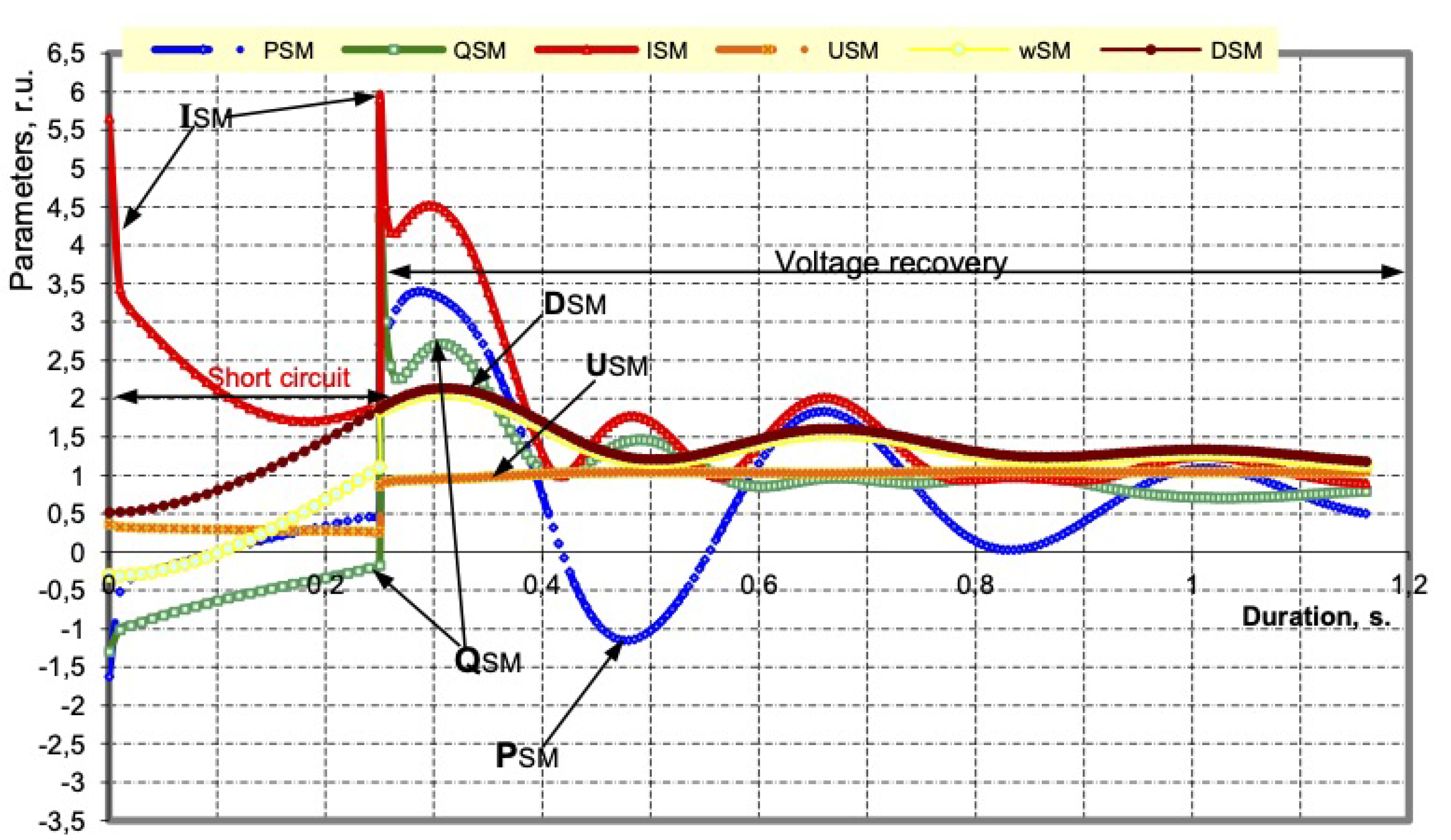
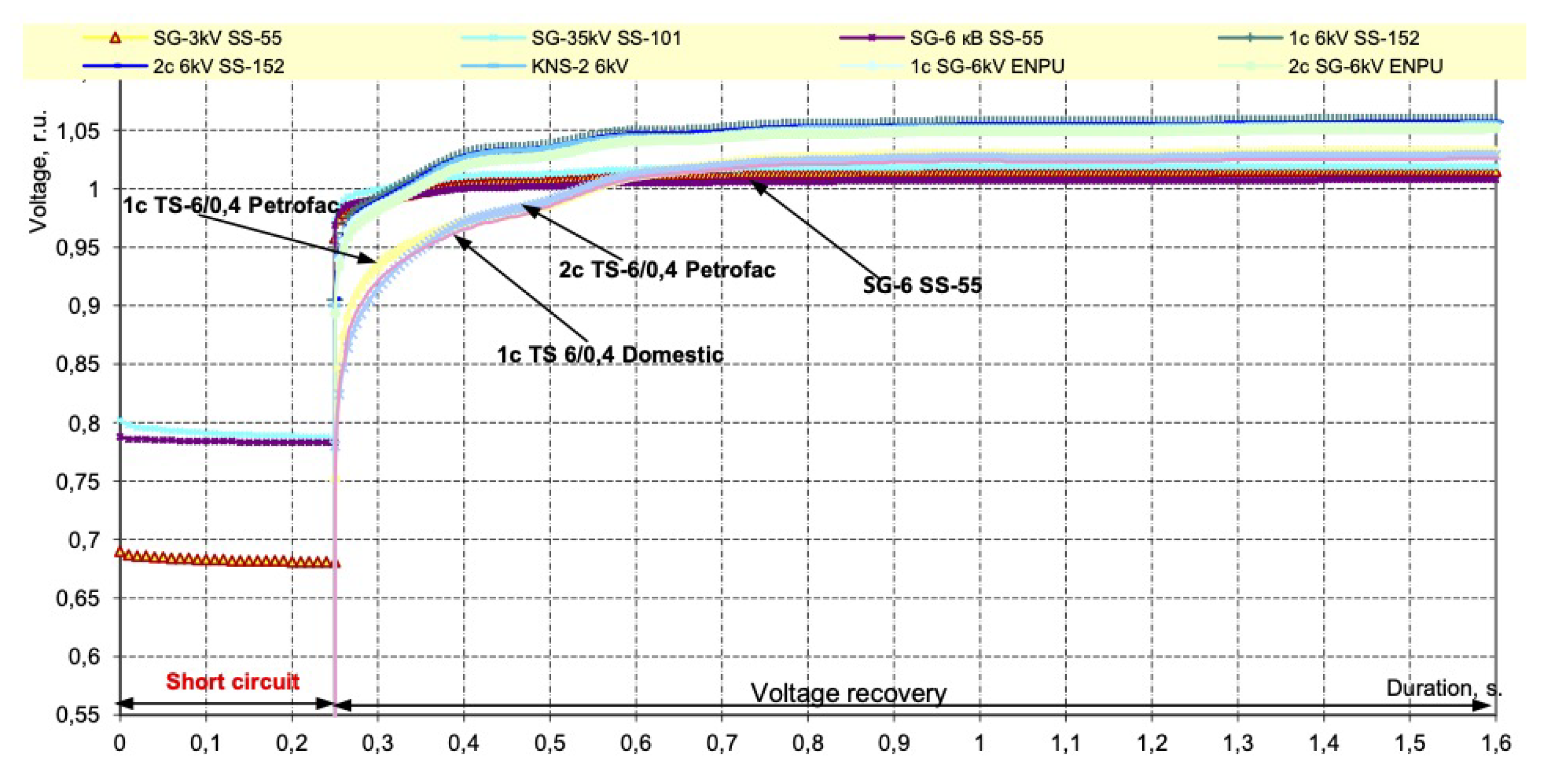
The HSBT protection zone does not include all types of short circuits in 6 kV electrical networks, on outgoing lines from the first (second) section of the 6 kV switchgear of an oil refinery (for example, node 39 and place K4).
The critical time of power failure t c t is understood as the time at which, when exceeded, there is a distortion of the stability of the electric motor load, the switching on of technological protections, or distortion of the continuity of the process plant. The value of the critical time is determined by the type and location of the short circuit in the power supply system and power supply interruptions not related to the short circuit. The operation of the HSBT device is designed in such a way that with a reliable determination of the SPOs above the place of its installation and a change in the direction of active power (current), a signal is simultaneously issued to turn off the switches Q10 (Q13) and turn on the sectional switch Q25.
To determine the critical time of a power failure, we set the calculated location and type of short circuit, and then we changed its duration from 0.04 to 0.5 s. The studies were carried out for networks with a voltage of 110 kV at nodes 1 and 5; networks with a voltage of 35 kV at nodes 11 and 2; and networks with a voltage of 6 kV at nodes 21 and 24. The calculations determined the following:
1.
The critical time of power failure of 6 kV switchgear, determined by the loss of synchronism of the SM or the overturning of the AM, is as follows:
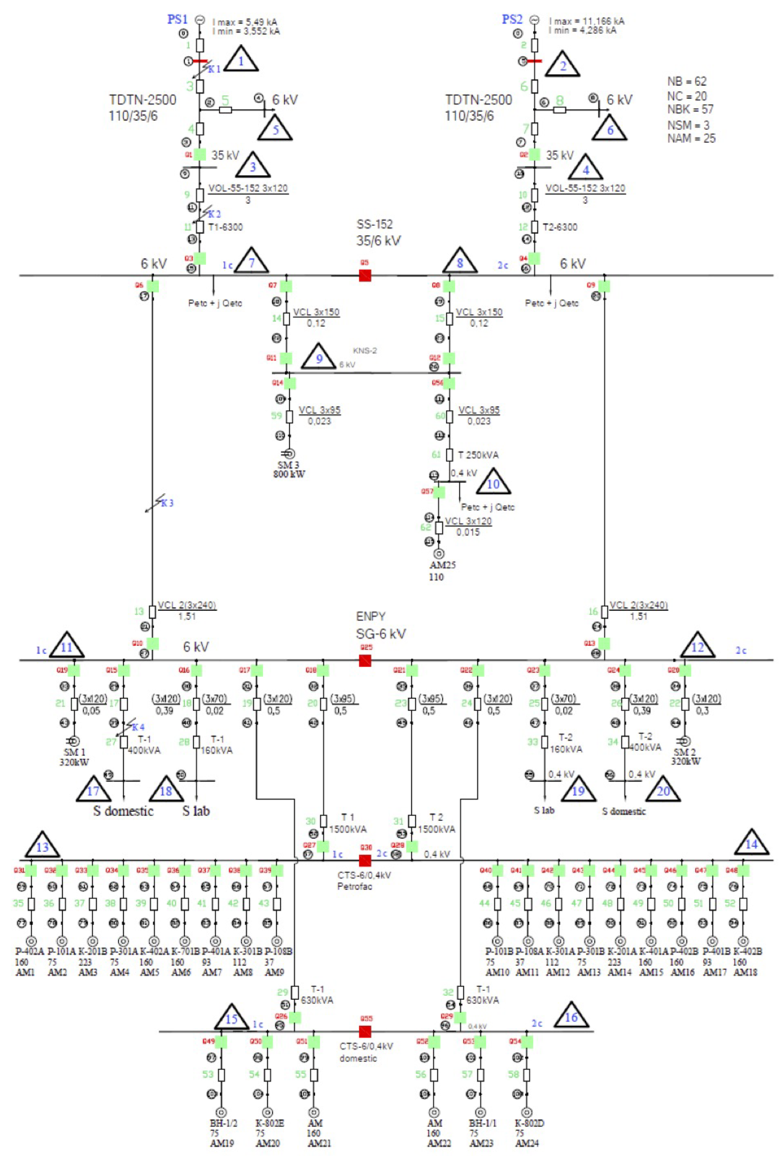
  • With a close three-phase short circuit in the 110 kV network, it equals 0.22 s;
  • With a close three-phase short circuit in the network 35 kV, it equals 0.25 s;
  • With a close three-phase short circuit in the network 6 kV, it equals 0.20 s;
  • In case of unauthorized disconnection of the switch in the power supply circuit of the substation, it equals 0.235 s.
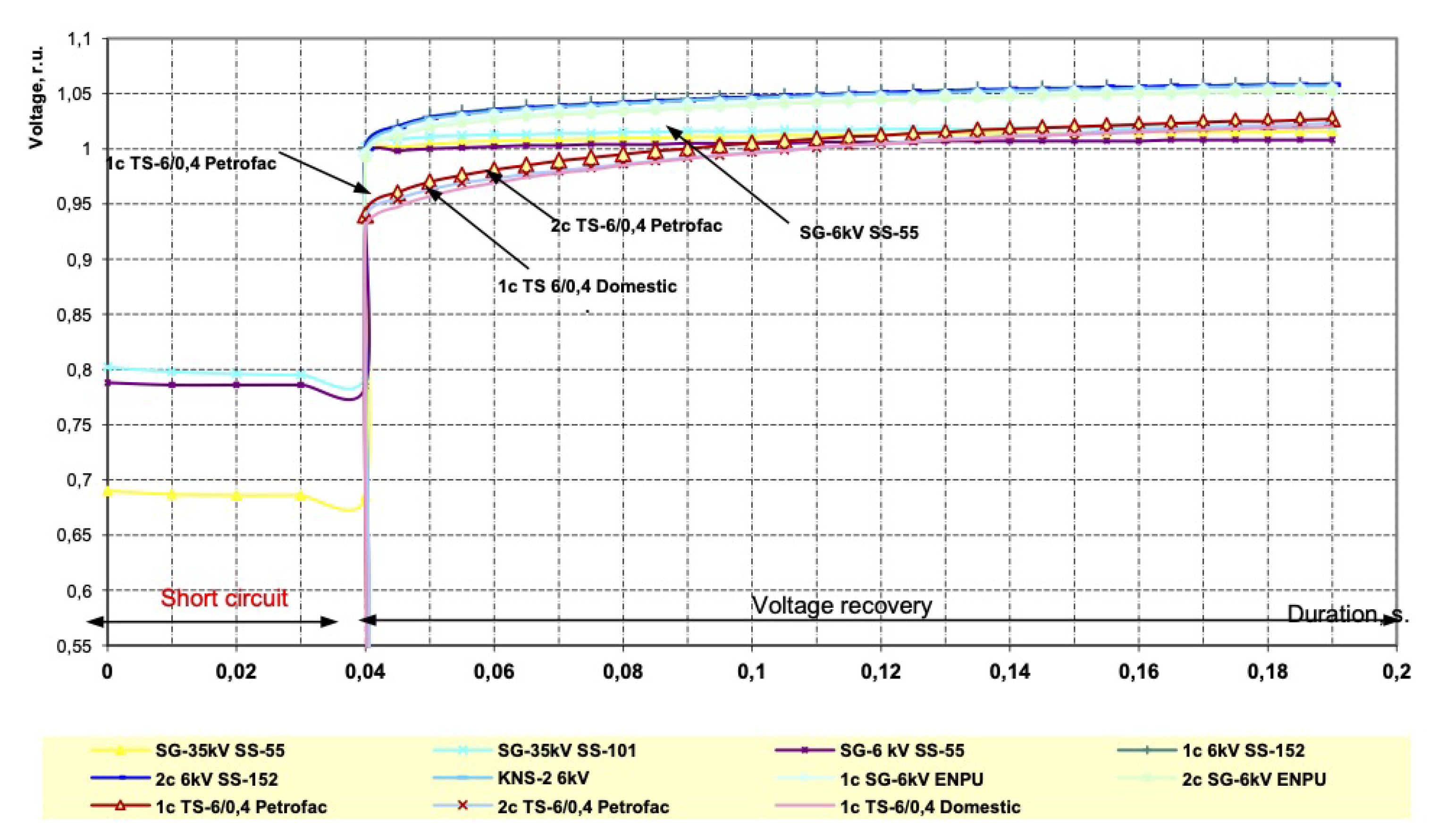
2.
The time for a complete switchover to the standby input will be as follows:
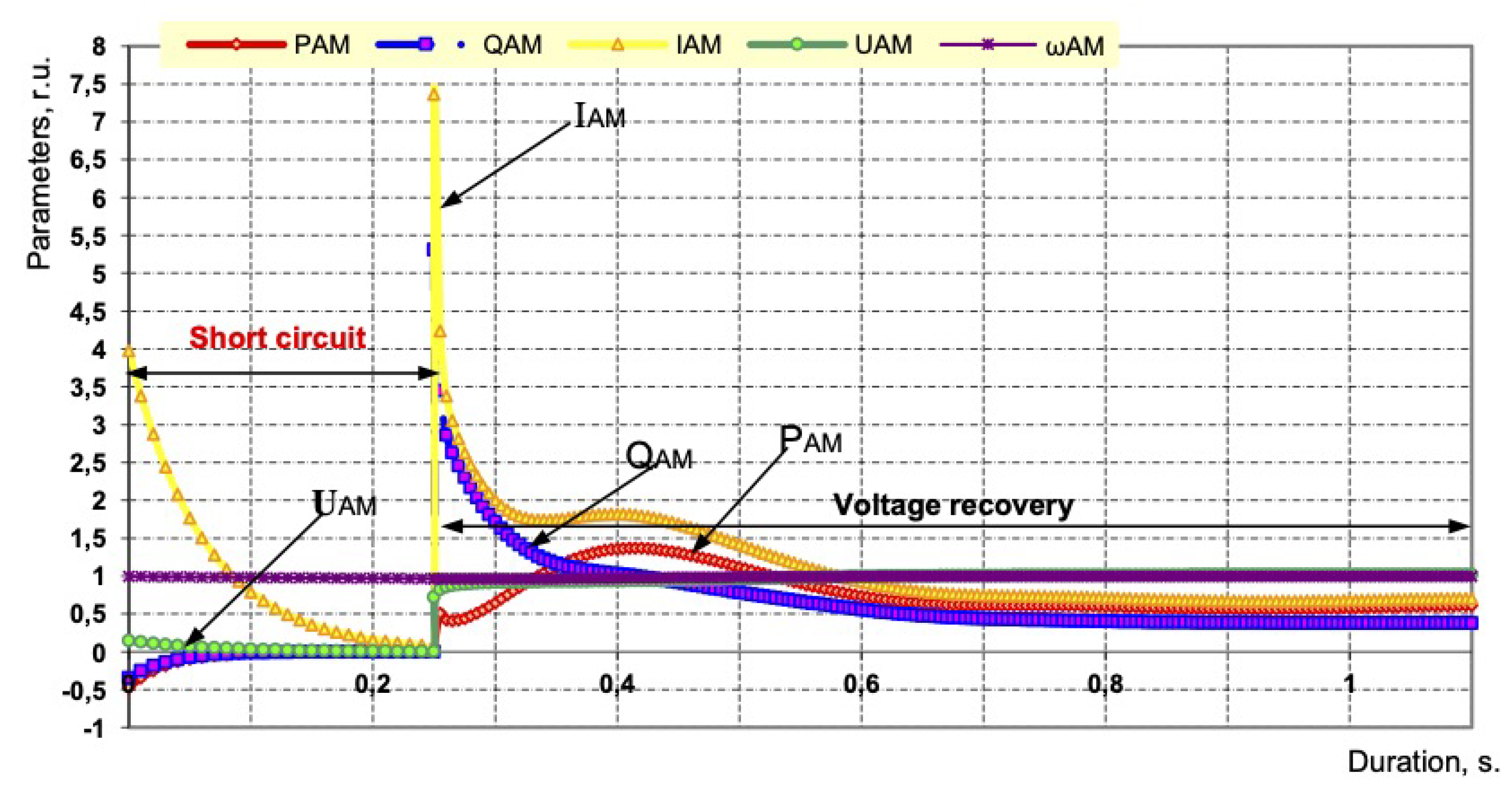
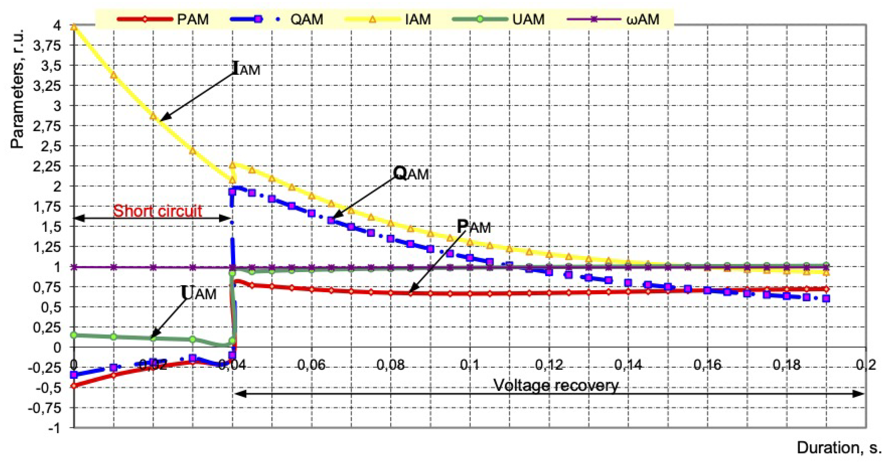
  • With a three-phase short circuit in the power supply circuit of the substation, t H S B T = 0.035 s;
  • In case of the unauthorized disconnection of the switch in the power supply circuit of the substation, t H S B T = 0.035 s.
3.
All asynchronous motors powered by 6 kV switchgear (including 380 V motors driving pumps, and compressors of the Petrofac unit) remain stable and ensure the continuous operation of the Petrofac unit with SPOs and the HSBT 072 device turned on.
The most severe trial for the 35/6 kV substation will be a three-phase short circuits in the 6 kV distribution network, electrically connected to the substation. To identify the features and verify the correctness of the choice of relay protection and automation parameters, studies of short circuits were carried out in node 21 of the equivalent circuit in Figure 1, when the short-circuit duration was changed and the results obtained were analyzed. After a short circuit in the 6 kV network (node 21) with a duration of 0.25 s, the coasting of all electric motors connected to the first section of the Petrofac installation starts. The nature of transient processes for AM-7 (R-401A Figure 1) is shown in Figure 4. The motor current at the initial moment does not exceed the starting value I S C = 3.98 < I P = 6.0 p.u. At the moment of voltage recovery after the short circuit is turned off after 0.25 s, the AM current fluctuates, which is caused by changes in the active (Figure 4) and reactive powers of all engines (their transition either to motor or generator mode, which follows from the work schedule). The reactive power of the AM during the coasting and self-starting does not exceed the value of Q A M = 5.3. The voltage at the terminals of the AM during the coasting on the short circuit decreases from U A M = 0.15. To U A M = 0 p.u., and at the moment of recovery, the voltage increases to U A M = 0.72 p.u. and by the time t = 0.29 s (from the beginning of the emergency mode), which reaches the value of U A M = 0.9 p.u. (Figure 4).
In the case of a short circuit in the 6 kV network (node 21) and the operation of the HSBT 072 in 0.04 s, the transient processes improve and the current of the AM-7 motor at the initial moment of voltage recovery does not exceed the starting value ( I t = 0.04 = 2.26 < I P = 6.0 p.u., Figure 5), and then, after one current fluctuation, the steady-state mode of the AM is established.
Due to the mutual influence of the functioning SM and AM, oscillations are observed in the transient process of the synchronous motor SM3. From the graph of the change in the active power of the SM (Figure 6) during the transition process, it can be seen that the engine passes from the motor to the generator mode of operation.
The current at the initial moment of voltage recovery is close to the starting one I t = 0.25 = 5.9 < I P = 6.4 p.u. The angle δ during self-starting exceeds 114 , and then after several oscillations reaches a steady value.
To ensure the continuous operation of the Petrofac process plant, it is important that the voltages on the sections do not become less than the critical voltage, equal to 0.75 ÷ 0.8 U n o m , at which the protection of the ASD and contactors (highlighted by * in Table 1) connected in the motor power circuits will turn on.
Studies have determined that the voltages on the sections depend on the duration of the short circuit (Table 1), and the nature of the residual stresses depends on taking into account the mutual influence of the operating electric motors (Figure 7).
From computational studies, it is clear that with a short circuit of more than 0.2 s duration, the residual voltages on the sections of the Petrofac installation are less than 0.75 p.u., which will lead to the shutdown of the AM due to the operation of starters and contactors (marked with * in Table 1). When HSBT 072 is operating for 0.04 s, the voltage on the buses of the TS and 6 kV switchgear sections is greater then 0.9 U n o m and there will be no stoppage of the Petrofac line (Figure 8).
Numerous implementations of HSBT 072 devices at real facilities of petrochemical, metallurgical, mining and processing, oil/gas producing, and chemical enterprises allowed to formulate the following requirements for the HSBT device:
1.
Reaction time to emergency mode should not exceed 10 ms;
2.
The total time of switching to a backup source is not more than 19 ÷ 65 ms;
3.
The desired disconnection time from an external short circuit is less than 20 ms.
With such operating times of the HSBT, the uninterrupted operation of the technological processes of most industries will be provided [2,8,11,16,20,26].
Table 2 shows the operation parameters of the devices HSBT 072.01 (reaction time is 11 ÷ 22 ms) and HSBT 072.20 (reaction time is 3 ÷ 9 ms) as part of electrical complexes at substations with voltages of 6 and 10 kV, obtained from the operation data. The results reflect the work carried out on the modernization of both the HSBT 072 device (from version 01 to version 20) and the impact of vacuum circuit breakers.
From the results obtained, the following was revealed:
  • The reaction time of the HSBT 072 device is reduced from 13 to 3 ms (there are oscillograms of the device operation at operating enterprises for 3, 5 and 6 ms), which makes it possible to significantly reduce the motors slowing down during short circuits in the supply networks (see Table 2; the short-circuit time varies from 11 to 62 ms);
  • The minimum short-circuit coasting time, taking into account the operation of the HSBT 072.20 device and the KEPS-VV 10-1600/25 circuit breakers, was 11 ms, i.e., half-cycle of current or voltage, which is comparable to UPS devices;
  • HSBT 072.20 complex, together with ISM15_Shell_FT2 circuit breakers for currents up to 2000 A, provides a total switching time to a backup source of 25 ÷ 31 ms, which in most TES maintains uninterrupted operation of drives with voltages of 6, 10 and 0.4 kV, because it ensures the voltage on the switchgear busbars at the time of recovery over 0.89 U n o m , as well as the minimum reduction in the angular frequency of rotation of the electric motors.
  • The HSBT 072.20 complex together with the KEPS-VV 10-2000/31.5 circuit breakers for currents up to 2000 A provides a full switching time to the backup source of 17 ÷ 23 ms, which will ensure the uninterrupted operation of drives with ASD for consumers with a voltage of 0.4 kV.
  • The choice of circuit breakers depends both on the preferences of the customers, the remoteness of the switchgear as well as transformer substations from the supply substations, and the presence of high-voltage motors in operation, as well as the requirements for the operating times of the HSBT complex.
Currently, we have experience in the implementation and operation of HSBT 072 complexes with 25 types of vacuum and/or SF6 circuit breakers.
The introduction of more than 450 intelligent automation devices HSBT 072 with different TES load composition confirmed both the indicated operating times of the device and a high-reliability indicator of operation, equal to 0.96 ÷ 0.98, in all cases of device operation.
The advantages of the proposed HSBT are as follows:
  • Instantaneous (minimum) reaction time to emergency mode equals 3 ÷ 9 ms;
  • Switching to the reserve input is always carried out in compliance with the common-mode power supplies;
  • It works with asymmetric short circuits in the power supply system, which account for more than 80% of all short circuits, using power direction control and a special current direction relay;
  • It works reliably both with synchronous and/or asynchronous motors with a voltage of 6, 10 kV, and without them;
  • It works with voltage and current distortions, without creating distortions itself, affecting the quality of electricity in the supply network;
  • It has a power thyristor key at the output of the device instead of a “dry” contact [12,31], which allows switching high-current circuits for switching on a sectional switch (for HSBT with a voltage of 35 kV).
Through the introduction of intelligent automation HSBT 072 at the 6 kV switchgear of the Petrofac installation in 2011–2012, which operates reliably and holds over 89% of the load, it was possible to avoid damages of USD 23.6 million (when 19 cases of short-term power outages occurred in external networks; Table 3).

4. Conclusions

1.
A technology is proposed for developing a mathematical model of an electrical complex with a combined (centralized and autonomous multi-unit) power sources to study the stability of electric motors and generators of stations.
2.
The mathematical model takes into account closed circuits in the network, controlling of the angles of the EMF of generators, and synchronous and asynchronous motors with regard to the EMF of the balancing node. This approach improves the accuracy of calculations of the range of acceptable modes during SPOs, residual voltages on the section buses, and flowing currents, and ensures the correct choice of parameters for relay protection and automation devices.
3.
The method of studying the stability of electrical systems in the case of their own generation is to determine the residual voltage levels in various nodes of the distribution network 35, 10, 6, and 0.4 kV. This takes into account closed loops, the structure and configuration of the network, and the operating modes of each connected synchronous motor or generator, as well as an asynchronous motor. The investigated electrical system is described by its system of differential equations with the calculation of the parameters of motors and generators as a function of the angular frequency of rotation.
4.
The developed device HSBT 072 with output power switches provides control of voltage, angle, direction of power (current) and current parameters of sections U min , U max , δ 12 , P , I min , I max . The device provides dynamic stability of the load nodes of the electrical complex with/without operating SM and AM high-voltage electric motors.
5.
The HSBT complex with a special current direction relay and operation from external protection provides a total switching time to a backup source of 17 ÷ 65 ms, depending on the type of circuit breakers used, and thus ensures the uninterrupted operation of the entire electrical complex.

Author Contributions

Conceptualization, V.P. and V.O.; formal analysis, V.O.; funding acquisition, V.P.; methodology, V.P. and V.O.; data curation, V.P.; investigation, V.P.; project administration, V.P. and V.O.; resources, V.P.; software, V.P.; supervision V.P. and V.O.; writing—original draft preparation, V.P. and V.O.; writing—review and editing, V.P. and V.O. All authors have read and agreed to the published version of the manuscript.

Funding

This research received no external funding.

Acknowledgments

The authors express their gratitude to the Editorial Board and reviewers for their attention to our work and comments that allowed us to improve the quality of our work.

Conflicts of Interest

The authors declare no conflict of interest.

References

  1. Abramovich, B.N.; Sychev, Y.A.; Zimin, R.Y. Hybrid system for correcting the level of higher harmonics and ensuring uninterrupted power supply for responsible oil production consumers. Ind. Energy 2018, 11, 50–57. [Google Scholar]
  2. Kusko, A.; Thompson, M. Quality of Electricity in Electrical Networks; Dodeka-XXI: Moscow, Russia, 2008. [Google Scholar]
  3. Beleiu, H.G.; Beleiu, I.N.; Pavel, S.G.; Darab, C.P. Management of Power Quality Issues from an Economic Point of View. Sustainability 2018, 10, 2326. [Google Scholar] [CrossRef]
  4. McGranaghan, M.; Roettger, B. Economic Evaluation of Power Quality. IEEE Power Eng. Rev. 2002, 22, 8–12. [Google Scholar] [CrossRef]
  5. Motoki, E.M.; Filho, J.M.C.; Silveira, P.M.; Pereira, N.B.; Souza, P.V. Cost of Indus-trial Process Shutdowns due to Voltage Sag and Short Interruption. Energy 2021, 14, 2874. [Google Scholar] [CrossRef]
  6. Gamazin, S.I.; Pupin, V.M.; Dolmatsin, M.I.; Khomutov, A.P. Improving the Reliability of Operation of Oil Pipeline Substation Circuits in Case of Short Circuits; VNIIOENG: Moscow, Russia, 1987. [Google Scholar]
  7. Gurevich, Y.E.; Libova, L.E. Application of Mathematical Models of Electrical Load in the Calculations of the Stability of Energy Systems and the Reliability of Power Supply to Industrial Consumers; Eleks-KM: Moscow, Russia, 2008. [Google Scholar]
  8. Ershov, M.S.; Egorov, A.V.; Trifonov, A.A. Sustainability of Industrial Electrical Systems; Publishing House Nedra: Moscow, Russia, 2010; p. 319. [Google Scholar]
  9. Sivokobylenko, V.F.; Derkachev, S.V. Analysis of transient processes in the motor load during power switching to a backup source. News High. Educ. Inst. Electromech. 2016, 5, 69–74. [Google Scholar]
  10. Kanerva, S. Simulation of Electrical Machines, Circuits and Control Systems Using Finite Element Method and System Simulator. Ph.D. Thesis, Helsinki University of Technology, Espoo, Finland, 2005. [Google Scholar]
  11. Singh, C.; Jirutitijaroen, P.; Mitra, J. Electric Power Grid Reliability Evaluation: Models and Methods; Wiley-IEEE Press: Hoboken, NJ, USA, 2018. [Google Scholar]
  12. Gurevich, Y.E.; Ilyushin, P.V. Peculiarities of Calculations of Regimes in Power Regions With Distributed Generation: Monograph; Nizhny Novgorod Institute of Management— A Branch of the Russian Academy of National Economy and Public Administration under the President of the Russian Federation: Nizhny Novgorod, Russia, 2018. [Google Scholar]
  13. Zakutnov, V.A.; Pupin, V.M.; Fedorov, O.V. Ensuring the working conditions of treatment facilities in the presence of mini-CHP. Bull. South Ural. State Univ. Ser. Energy 2021, 21, 75–81. [Google Scholar]
  14. Weldemariam, L.E.; Cuk, V.; Cobben, J.F.G. Impact of voltage dips monitored in the MV networks on aggregated customers. Electr. Power Syst. Res. 2017, 149, 146–155. [Google Scholar] [CrossRef]
  15. Patrick, J.C.; William, H.G.; Thomas, W.Y. Refinery Power Failures: Causes. Costs and Solutions; Hydrocarbon Publishing Company: Frazer, PA, USA, 2013; pp. 1–6. [Google Scholar]
  16. Weldemariam, L.E.; Cuk, V.; Cobben, J.F.G. Cost Estimation of Voltage Dips in Small Industries Based on Equipment Sensitivity Analysis. Smart Grid Renew. Energy 2016, 7, 271–292. [Google Scholar] [CrossRef]
  17. Almeida, A.; Moreira, L.; Delgado, J. Power Quality Problems and New Solutions. RE&PQJ 2003, 1, 25–38. [Google Scholar] [CrossRef]
  18. Andreev, V.A. Relay Protection and Automation of Power Supply Systems; Higher School: Moscow, Russia, 2007. [Google Scholar]
  19. Bederak, Y.; Borodin, D.; Mikhailov, V. Networks of industrial enterprises. Devices Prot. Against Volt. Dips 2012, 1. [Google Scholar]
  20. Ershov, S.V.; Pigalov, M.S. Analysis of means and methods for limiting the influence of voltage dips. Bull. Tula State Univ. Tech. Sci. 2017, 1, 95–104. [Google Scholar]
  21. Raje, A.; Raje, A.; McCall, J.; Chaudhary, A. Bus transfer systems: Requirements. implementation and experiences. IEEE Trans. Ind. Appl. 2003, 39, 34–44. [Google Scholar] [CrossRef]
  22. Di Maio, L.; Gemme, C.; Krumm, R. Fast power switchover keeps production lines running. ABB Rev. 2002, 2, 38–42. [Google Scholar]
  23. Maio, L.D.; Andenna, A.; Gatelli, F.; Crespi, A. High Speed Transfer System. PCT/EP02/14489, 10 July 2003. [Google Scholar]
  24. Pupin, V.M.; Kuftin, D.S.; Frolov, A.V.; Sviridov, Y.P. Calculation of the conditions for the occurrence of hydraulic shocks in water supply and sewerage systems. Electrician 2011, 1, 21–26. [Google Scholar]
  25. Aptekar, D.I.; Rubashev, G.M.; Chikankov, D.V. Methods and means of improving the reliability of power supply to responsible consumers. News Electr. Eng. 2001, 2. [Google Scholar]
  26. Yasir, M.; Kazemi, S.; Lehtonen, M. Optimal Selection of Voltage Sag Mitigation Solution Based on Event Tree Method. In Proceedings of the Fotuhi-Firuzabad. Electric Power Quality and Supply Reliability, Tartu, Estonia, 11–13 June 2012; pp. 1–6. [Google Scholar]
  27. Hindmarsh, J. Electrical Machines and Drives Worked Examples, 2nd ed.; Second edition 1985 Reprinted with corrections 1988. 1991 Printed in Great Britain by BPCC Wheatons Ltd. Exeter; Pergamon Press Inc.: Elmsford, NY, USA, 1982; p. 10523. [Google Scholar]
  28. Mariesa, L. Crow Computational Methods for Electric Power Systems, 2nd ed.; CRC Press: Boca Raton, FL, USA, 2010. [Google Scholar]
  29. Paliwal, M.; Verma, R.; Rastogi, S. Voltage sag compensation using dynamic voltage restorer. Adv. Electron. Electr. Eng. 2014, 4, 645–654. [Google Scholar]
  30. Pachar, R.K.; Tiwari, H. Performance Evaluation of Static Transfer Switch. WSEAS Trans. Syst. Control 2008, 3, 137–148. [Google Scholar]
  31. Zhukov, V.A.; Pupin, V.M. A Method for Automatically Switching on the Backup Power Supply to Consumers (Options) and a Device for Its Implementation. Patent No. 2398338, 27 August 2010. [Google Scholar]
  32. Zhukov, V.A.; Pupin, V.M. Method and Device for the High-Speed Automatic Activation of A Backup Consumer Electrical Power Supply. U.S. Patent 8680718B2, 25 March 2014. [Google Scholar]
Figure 1. Electrical diagram of the technical electrical complex of an oil refinery with the Petrofac installation.
Energies 16 04184 g001
Figure 3. Structural diagram of HSBT devices: (a) is a diagram of a classic switchgear, SS; (b) is the scheme with two inputs per section 6 (10) kV.
Energies 16 04184 g003
Figure 4. Parameters of AM-7 with a three-phase short circuit in a 6 kV network (node 21) with t S C = 0.25 s duration.
Energies 16 04184 g004
Figure 5. Parameters of AM-7 with a three-phase short circuit in a 6 kV network (node 21) with 0.04 s duration.
Energies 16 04184 g005
Figure 6. SM parameters with a three-phase short circuit ( t S C = 0.25 s) in a 6 kV network.
Energies 16 04184 g006
Figure 7. Section voltages during short circuit in the network 6 kV (s) and during the power supply recovery.
Energies 16 04184 g007
Figure 8. Section voltages in case of short circuit in the 6 kV network during the operation of the HSBT 072 ( t H S B T = 0.04 s) and power supply recovery.
Energies 16 04184 g008
Table 1. Voltages on the switchgear and TS sections at the first moment of self-starting.
Device Type t SC , s6 KW Switchgear
Elkhovskaya Oil Refinery
TS-6/0.4 PetrofacTS-6/0.4 Aux. Corp
1 section2 section1 section1 section2 section1 section
ATS0.250.8930.8940.754 * 0.780 * 0.739 * 0.791 *
ATS0.220.8920.8960.743 * 0.784 * 0.719 * 0.794 *
HSBT 0720.040.9940.9920.9400.9360.9260.937
Table 2. Parameters of HSBT 072.01 and HSBT 072.20 with a voltage of 6, 10 kV.
Switch Type, Output ContactResponse Time to Emergency Mode, msSwitch On/Off Time, msHSBT Time for the Switching Circuit, msCoasting Time on a Short Circuit, Taking into Account the HSBT *, ms
BB/TEL Shell Q
with “dry contact”
1322/83721
1122/83519
Vacuum circuit breakers
WB/TEK,
1250 with JGBT-key
945/405449
947/405650
Evolis, 1600A8
with JGBT-key
71/527960
972/508159
Evolis, 1600A with
“dry contact”
1171/508261
1272/508462
VF12, 1250A
with JGBT-key
1242/305442
1244/305642
VF12, 3150A
with JGBT-key
1245/305742
1247/305942
SION 3AE 1055
with JGBT-key
850/375845
949/375846
Siemens ZAK 1637-5,
3150A
with JGBT
661/456751
861/456953
VD4, 630A
with “dry contact”
1252/406452
ISM15_Shell_FT2 with
JGBT-key
922/103119
KEPS-VV 10-1600/25314/81711
* defined as the sum of HSBT 072 reaction time and circuit breaker opening time.
Table 3. Data on the operation of the HSBT 072.01 device.
Date and Hour of SPOVoltage Dip ValueCurrent I 1 + I 2 before Failure kACurrent I 1 + I 2 after Failure, kARemaining Load Value T HSBT , ms
13 January 2017 01:00:28U A , B S 1 = 89%.
U B , B S 1 = 52%.
U C , B S 1 = 87%
0.1820.17496%30 ms
15 January 2017 19:37:31U A , B S 1 = 85%.
U B , B S 1 = 83%.
U C , B S 1 = 49%.
0.1850.16489%30 ms
19 January 2017 21:25:18U A , B S 1 = 85%.
U B , B S 1 = 82%.
U C , B S 1 = 50%
0.1900.17693%30 ms
19 January 2017 22:40:37U A , B S 1 = 86%.
U B , B S 1 = 87%.
U C , B S 1 = 52%
0.1820.182100%30 ms
Disclaimer/Publisher’s Note: The statements, opinions and data contained in all publications are solely those of the individual author(s) and contributor(s) and not of MDPI and/or the editor(s). MDPI and/or the editor(s) disclaim responsibility for any injury to people or property resulting from any ideas, methods, instructions or products referred to in the content.

