Modeling of Electrical Systems for Uninterrupted Operation of Drives in Case of Short-Term Distortions in the Supply Networks
Abstract
:1. Introduction
2. Materials and Methods
2.1. Mathematical Model and Method for Studying an Electrical System
- Electromagnetic transient processes along the longitudinal axiswhere are the time constants of the transient and super transient processes; are the longitudinal and transverse components of the synchronous (supertransient) EMF along the axes; are synchronous inductive resistances along the d and q axes; are supertransient inductive resistances along the d and q axes; is the voltage across the transverse winding of the SM stator; is the excitation winding voltage; is the time constant determined by the leakage inductance of the equivalent damper circuit; is the transient resistance of the SM along the d axis, taking into account the influence of the damper circuit; and is the synchronous EMF of the motor in the nominal mode. A synchronous motor is represented by a classical SM equivalent circuit along the longitudinal () and transverse () axes [6].
- Electromagnetic transients along the transverse axis
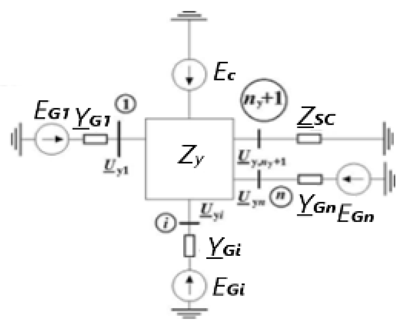
- For the first level (from the supply system to the load nodes, Figure 2):where is the underscore symbol that means a vector quantity.
- For the second level (from load nodes to SM and AM outputs):
- For the third level (for engines):
- 1.
- is the voltage on the first section in the initial mode;
- 2.
- and are load factors of the i-th synchronous and j-th asynchronous motors ( 1,; 1,;
- 3.
- is the power factor of the i-th SM in the initial mode ;
- 4.
- and are the active and reactive powers of the other load of the i-th node at rated voltage ();
- 5.
- is the power of capacitor banks connected to the j-th node (.
- 1.
- It is assumed that the first synchronous generator is a balancing node and the equivalent circuit node to which it is connected is defined by the number “1”, then the load node at the number “1” coincides with the node “1” of the equivalent circuit. To calculate the section stresses, in normal mode, the voltage at the load node “1” is taken as the initial one.
- 2.
- 3.
- 4.
- When the TES is disconnected from the power system, the TES equivalent circuit is represented as a circuit of “n − 1” independent load nodes, which contain both an electric motor and other loads with nodal currents ( ….
- 5.
- When the TES mini-station operates separately, the matrix of the connection path for any network element has the following features:
- The path from the 1st load node does not contain branches.
- 6.
- The system of equations for calculating the steady state is determined through the nodal stresses, expressed by the matrix of nodal resistances:where
- 7.
- To calculate the steady-state TES mode, we solve the system of nonlinear equations of the TES mode by using the method of successive approximations. For the initial approximation of nodal voltages, we take the nominal voltages of nodes with the same voltage phase , which coincides with the voltage phase of the balancing node [6,10].
- 8.
- Initial approximations of nodal currents are taken from the initial nodal voltages .
- 9.
- 10.
- 11.
- 12.
- Then we consider that the specified accuracy of the mode calculation is achieved and the values of [6,10] are taken as nodal stresses.The nodal current is defined as the sum of the branch currents:Knowing the current and voltage , we find the power supplied to the balancing node . Since this power is expressed in relative units through the base power , and the power of the first generator is expressed in fractions of its total power , the power of the first generator is recalculated in fractions [6,10].
- 13.
- Having determined the voltages in all load nodes, we find the parameters of the first SG mode: currents, active and reactive powers, voltage components for the longitudinal and transverse axes, EMF for normal, transient and supertransient processes.
- 1.
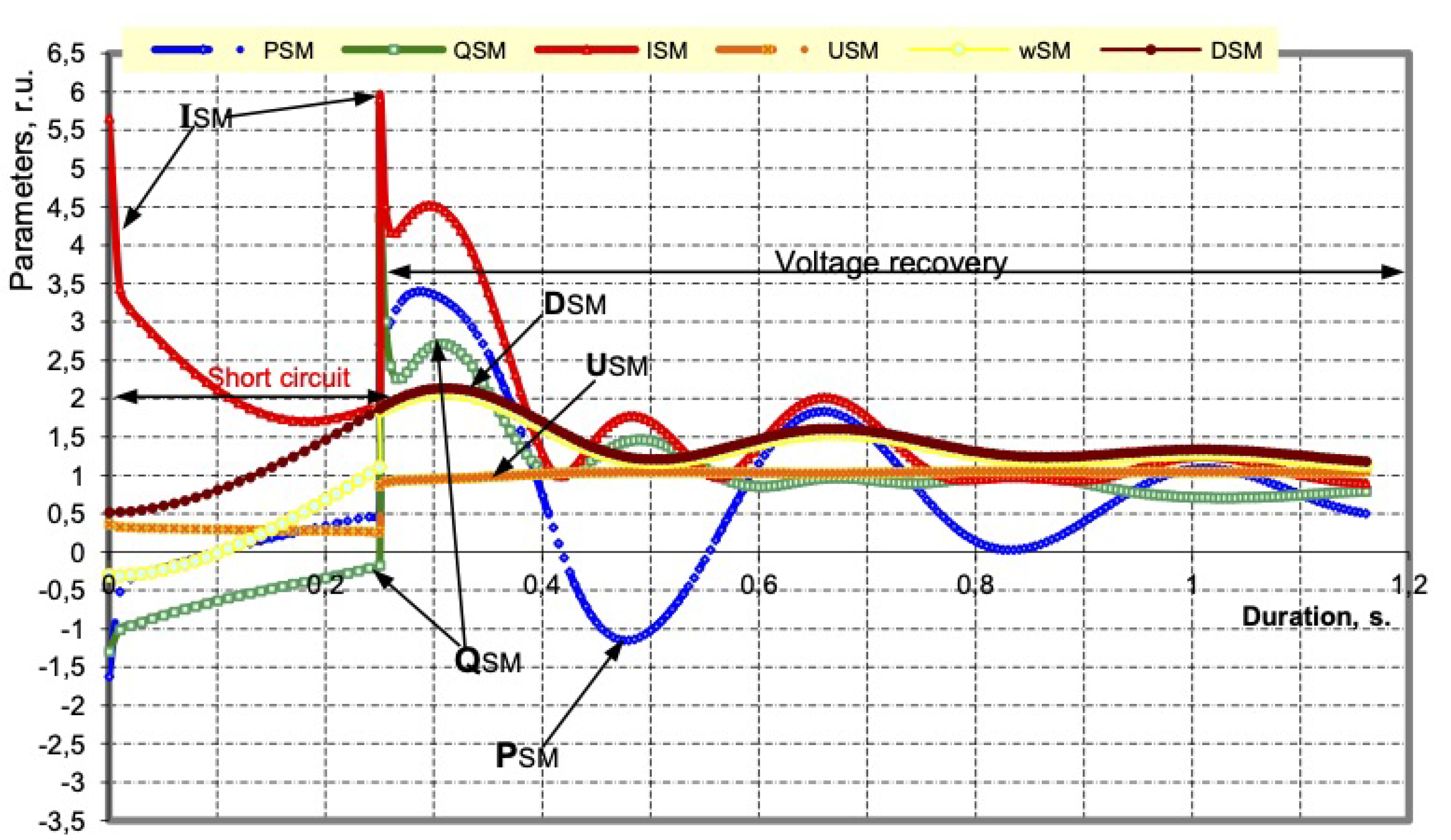
- The mathematical model of a working SM in transient processes during short circuit is represented by a system of differential Equations (1)–(4), and AM is a system of three differential Equation (5) [6,10]. The mathematical model of the power system and the intra-plant network of the enterprise includes all power sources (set by their parameters), lines, transformers, reactors, loads of each switchgear, substation with a voltage of 110, 10, 6 and 0.4 kV, and parameters of relay protection and automation (RPA) [6,10]. The developed software package TKZSG implements the above method for calculating transients for different types of short circuits and allows to take into account 225 SM and 500 AM (A.S. No. 2016615994 Ros. Federation. Research program for operating modes of an electrical complex with its own generation from the power supply system to consumers with a voltage of 380V TKZ_SG/applicant and copyright holders V.A. Zakutnov, V.M. Pupin; No. 2016614257; dec. 20 April 2016; reg. 2 June 2016).
- 2.
- By means of the state of switching devices, the accounting for topological changes in the network, the logic of the relay protection and automation equipment (RPAE) at the stages of short-circuit coasting after the short circuit is turned off and when the normal power supply is recovered is modeled.
- 3.
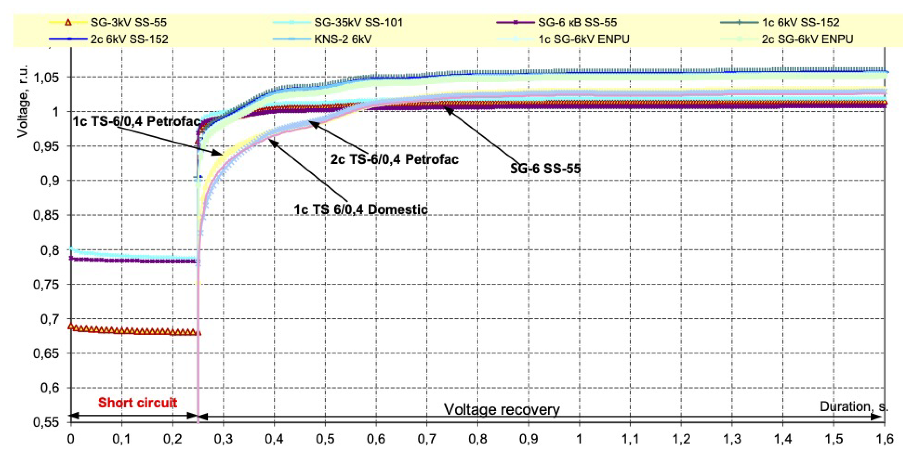
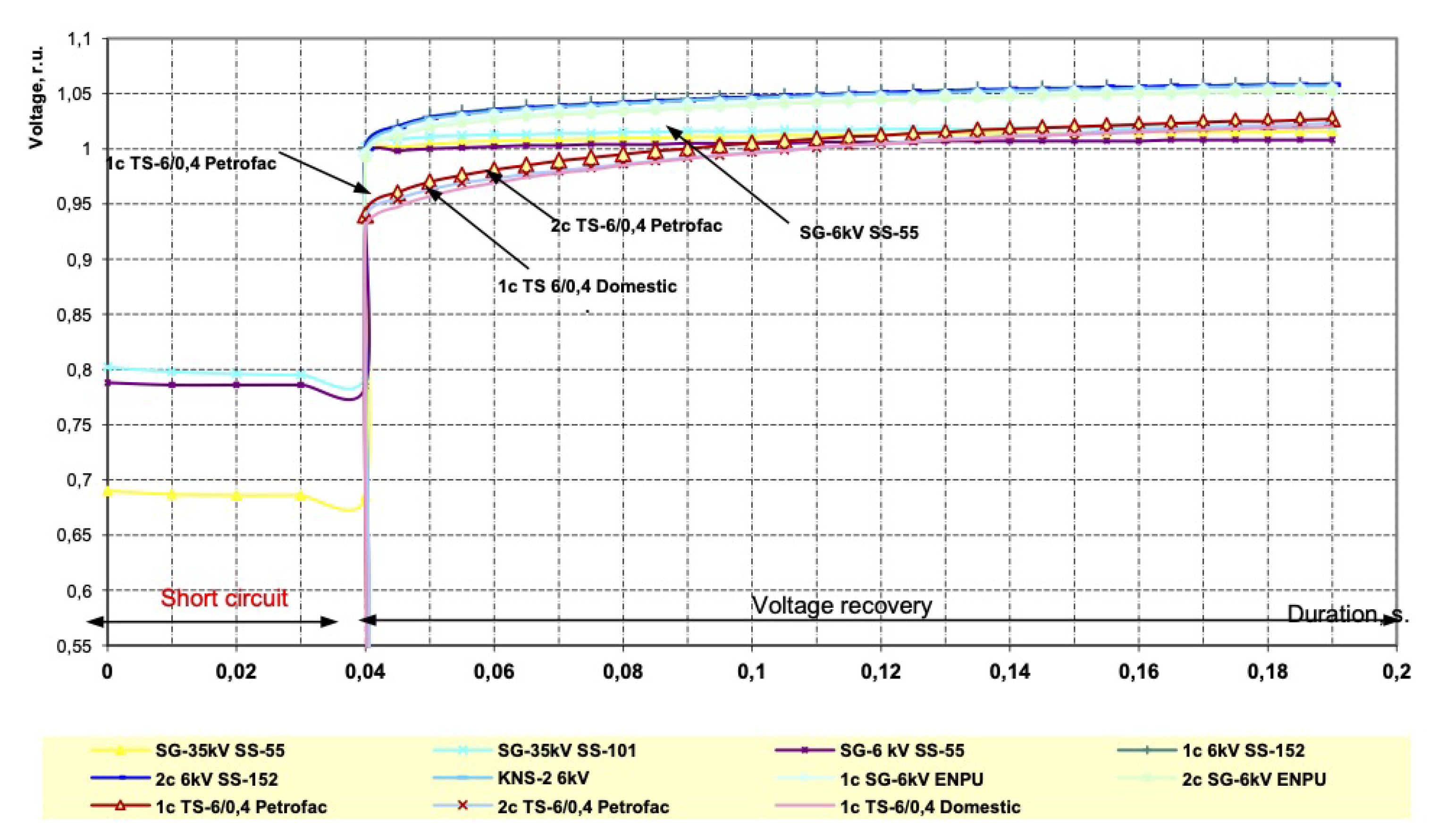
- The simulation of transient processes is accompanied by the use of software modules for the automatic output of voltage graphs of all switchgear sections, as well as tabular parameters of the operating mode of the nodes sections (active and reactive power, currents, and load voltage), SM and AM.
2.2. Instantaneous Automatic Backup Power Input for Uninterrupted Operation of Complex Loads
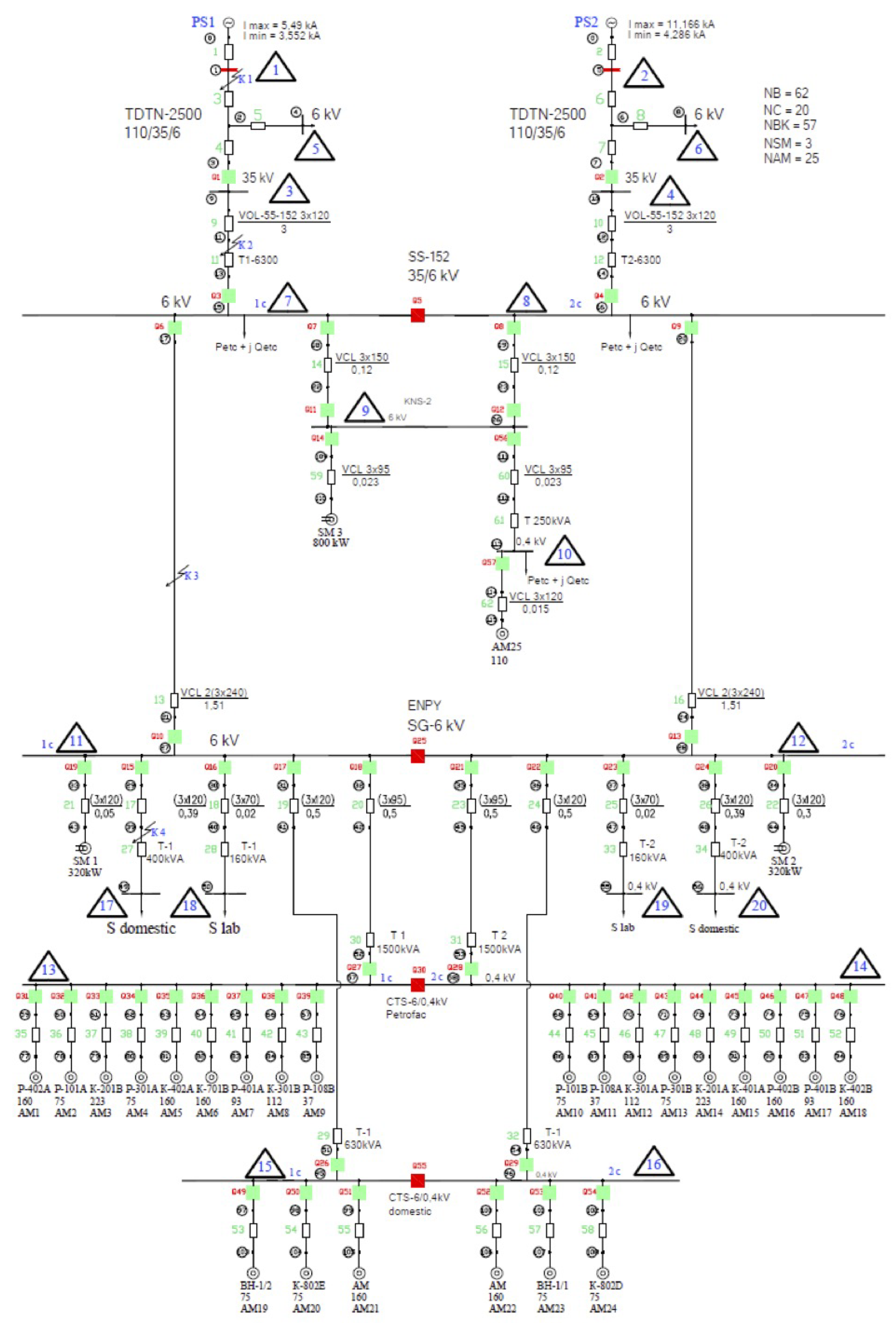
- All types of short circuits (three-phase, interphase, single-phase, two-phase to ground) in one of the power circuits of the 110 (220) kV network (Figure 3).
- Unauthorized cutoffs of circuit head switches (HS1 and HS2 Figure 3) in the network 110 and 35 kV.
- All types of external short circuits in 110, 35 and internal 6, 10 kV networks, causing voltage dips that are dangerous for the operation of TES drives.
3. Discussion of Results
- Various types of short circuits (three-phase, interphase, single-phase, two-phase to ground, node 1 (5) and place K1) in the power supply circuit of the 110 kV network SS-152.
- Short circuits (three-phase and phase-to-phase) both in one of the power circuits and on the outgoing line 35 kV SS-152 (node 11(12) and place K2).
- Unauthorized tripping of circuit breakers in the power supply circuit at a voltage of 110 and 35 kV (Q1(Q2)).
- All types of external short circuits in electrical networks of 110 and 35 kV, causing voltage dips, dangerous for process drives of the Petrofac plant, the equipment of which is connected to SS-152.
- Unauthorized tripping of switches Q3 and Q4.
- Three-phase short circuits in the 6 kV network above the installation site of the HSBT (node 21).
- 1.
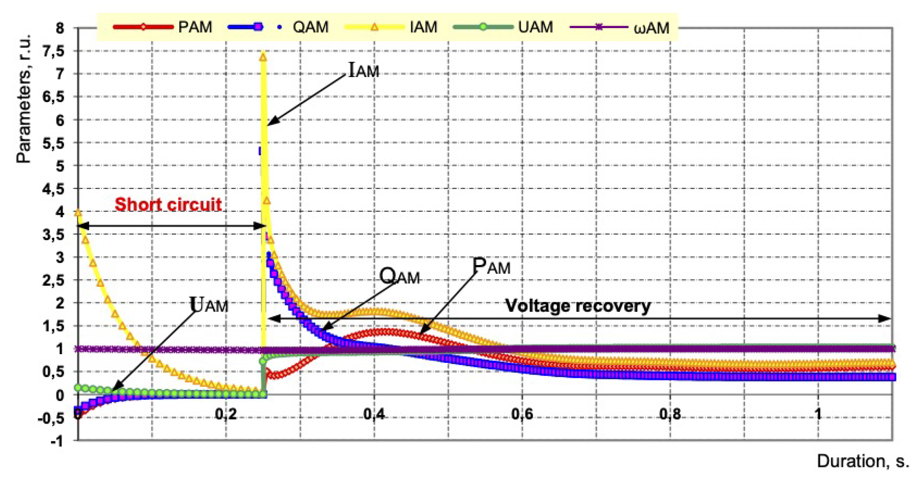
- The critical time of power failure of 6 kV switchgear, determined by the loss of synchronism of the SM or the overturning of the AM, is as follows:
- With a close three-phase short circuit in the 110 kV network, it equals 0.22 s;
- With a close three-phase short circuit in the network 35 kV, it equals 0.25 s;
- With a close three-phase short circuit in the network 6 kV, it equals 0.20 s;
- In case of unauthorized disconnection of the switch in the power supply circuit of the substation, it equals 0.235 s.
- 2.
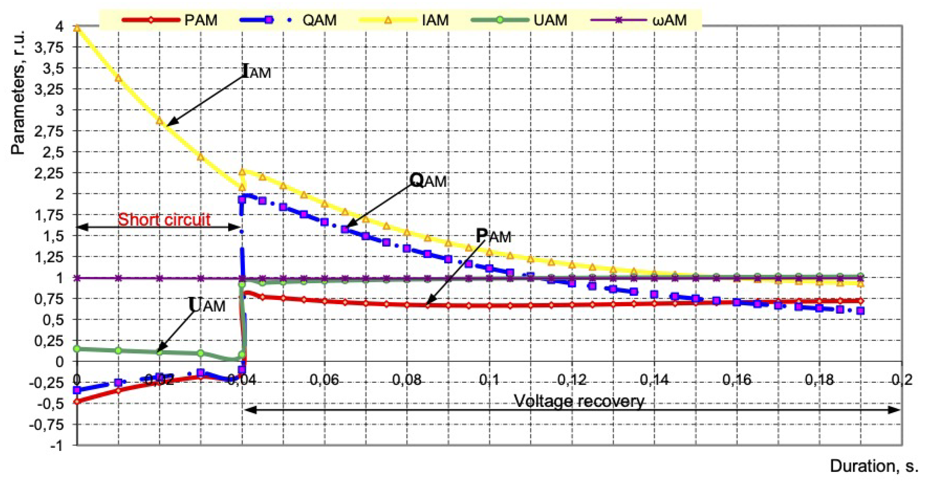
- The time for a complete switchover to the standby input will be as follows:
- With a three-phase short circuit in the power supply circuit of the substation, 0.035 s;
- In case of the unauthorized disconnection of the switch in the power supply circuit of the substation, 0.035 s.
- 3.
- All asynchronous motors powered by 6 kV switchgear (including 380 V motors driving pumps, and compressors of the Petrofac unit) remain stable and ensure the continuous operation of the Petrofac unit with SPOs and the HSBT 072 device turned on.
- 1.
- Reaction time to emergency mode should not exceed 10 ms;
- 2.
- The total time of switching to a backup source is not more than 19 ÷ 65 ms;
- 3.
- The desired disconnection time from an external short circuit is less than 20 ms.
- The reaction time of the HSBT 072 device is reduced from 13 to 3 ms (there are oscillograms of the device operation at operating enterprises for 3, 5 and 6 ms), which makes it possible to significantly reduce the motors slowing down during short circuits in the supply networks (see Table 2; the short-circuit time varies from 11 to 62 ms);
- The minimum short-circuit coasting time, taking into account the operation of the HSBT 072.20 device and the KEPS-VV 10-1600/25 circuit breakers, was 11 ms, i.e., half-cycle of current or voltage, which is comparable to UPS devices;
- HSBT 072.20 complex, together with ISM15_Shell_FT2 circuit breakers for currents up to 2000 A, provides a total switching time to a backup source of 25 ÷ 31 ms, which in most TES maintains uninterrupted operation of drives with voltages of 6, 10 and 0.4 kV, because it ensures the voltage on the switchgear busbars at the time of recovery over 0.89, as well as the minimum reduction in the angular frequency of rotation of the electric motors.
- The HSBT 072.20 complex together with the KEPS-VV 10-2000/31.5 circuit breakers for currents up to 2000 A provides a full switching time to the backup source of 17 ÷ 23 ms, which will ensure the uninterrupted operation of drives with ASD for consumers with a voltage of 0.4 kV.
- The choice of circuit breakers depends both on the preferences of the customers, the remoteness of the switchgear as well as transformer substations from the supply substations, and the presence of high-voltage motors in operation, as well as the requirements for the operating times of the HSBT complex.
- Instantaneous (minimum) reaction time to emergency mode equals 3 ÷ 9 ms;
- Switching to the reserve input is always carried out in compliance with the common-mode power supplies;
- It works with asymmetric short circuits in the power supply system, which account for more than 80% of all short circuits, using power direction control and a special current direction relay;
- It works reliably both with synchronous and/or asynchronous motors with a voltage of 6, 10 kV, and without them;
- It works with voltage and current distortions, without creating distortions itself, affecting the quality of electricity in the supply network;
4. Conclusions
- 1.
- A technology is proposed for developing a mathematical model of an electrical complex with a combined (centralized and autonomous multi-unit) power sources to study the stability of electric motors and generators of stations.
- 2.
- The mathematical model takes into account closed circuits in the network, controlling of the angles of the EMF of generators, and synchronous and asynchronous motors with regard to the EMF of the balancing node. This approach improves the accuracy of calculations of the range of acceptable modes during SPOs, residual voltages on the section buses, and flowing currents, and ensures the correct choice of parameters for relay protection and automation devices.
- 3.
- The method of studying the stability of electrical systems in the case of their own generation is to determine the residual voltage levels in various nodes of the distribution network 35, 10, 6, and 0.4 kV. This takes into account closed loops, the structure and configuration of the network, and the operating modes of each connected synchronous motor or generator, as well as an asynchronous motor. The investigated electrical system is described by its system of differential equations with the calculation of the parameters of motors and generators as a function of the angular frequency of rotation.
- 4.
- The developed device HSBT 072 with output power switches provides control of voltage, angle, direction of power (current) and current parameters of sections . The device provides dynamic stability of the load nodes of the electrical complex with/without operating SM and AM high-voltage electric motors.
- 5.
- The HSBT complex with a special current direction relay and operation from external protection provides a total switching time to a backup source of 17 ÷ 65 ms, depending on the type of circuit breakers used, and thus ensures the uninterrupted operation of the entire electrical complex.
Author Contributions
Funding
Acknowledgments
Conflicts of Interest
References
- Abramovich, B.N.; Sychev, Y.A.; Zimin, R.Y. Hybrid system for correcting the level of higher harmonics and ensuring uninterrupted power supply for responsible oil production consumers. Ind. Energy 2018, 11, 50–57. [Google Scholar]
- Kusko, A.; Thompson, M. Quality of Electricity in Electrical Networks; Dodeka-XXI: Moscow, Russia, 2008. [Google Scholar]
- Beleiu, H.G.; Beleiu, I.N.; Pavel, S.G.; Darab, C.P. Management of Power Quality Issues from an Economic Point of View. Sustainability 2018, 10, 2326. [Google Scholar] [CrossRef]
- McGranaghan, M.; Roettger, B. Economic Evaluation of Power Quality. IEEE Power Eng. Rev. 2002, 22, 8–12. [Google Scholar] [CrossRef]
- Motoki, E.M.; Filho, J.M.C.; Silveira, P.M.; Pereira, N.B.; Souza, P.V. Cost of Indus-trial Process Shutdowns due to Voltage Sag and Short Interruption. Energy 2021, 14, 2874. [Google Scholar] [CrossRef]
- Gamazin, S.I.; Pupin, V.M.; Dolmatsin, M.I.; Khomutov, A.P. Improving the Reliability of Operation of Oil Pipeline Substation Circuits in Case of Short Circuits; VNIIOENG: Moscow, Russia, 1987. [Google Scholar]
- Gurevich, Y.E.; Libova, L.E. Application of Mathematical Models of Electrical Load in the Calculations of the Stability of Energy Systems and the Reliability of Power Supply to Industrial Consumers; Eleks-KM: Moscow, Russia, 2008. [Google Scholar]
- Ershov, M.S.; Egorov, A.V.; Trifonov, A.A. Sustainability of Industrial Electrical Systems; Publishing House Nedra: Moscow, Russia, 2010; p. 319. [Google Scholar]
- Sivokobylenko, V.F.; Derkachev, S.V. Analysis of transient processes in the motor load during power switching to a backup source. News High. Educ. Inst. Electromech. 2016, 5, 69–74. [Google Scholar]
- Kanerva, S. Simulation of Electrical Machines, Circuits and Control Systems Using Finite Element Method and System Simulator. Ph.D. Thesis, Helsinki University of Technology, Espoo, Finland, 2005. [Google Scholar]
- Singh, C.; Jirutitijaroen, P.; Mitra, J. Electric Power Grid Reliability Evaluation: Models and Methods; Wiley-IEEE Press: Hoboken, NJ, USA, 2018. [Google Scholar]
- Gurevich, Y.E.; Ilyushin, P.V. Peculiarities of Calculations of Regimes in Power Regions With Distributed Generation: Monograph; Nizhny Novgorod Institute of Management— A Branch of the Russian Academy of National Economy and Public Administration under the President of the Russian Federation: Nizhny Novgorod, Russia, 2018. [Google Scholar]
- Zakutnov, V.A.; Pupin, V.M.; Fedorov, O.V. Ensuring the working conditions of treatment facilities in the presence of mini-CHP. Bull. South Ural. State Univ. Ser. Energy 2021, 21, 75–81. [Google Scholar]
- Weldemariam, L.E.; Cuk, V.; Cobben, J.F.G. Impact of voltage dips monitored in the MV networks on aggregated customers. Electr. Power Syst. Res. 2017, 149, 146–155. [Google Scholar] [CrossRef]
- Patrick, J.C.; William, H.G.; Thomas, W.Y. Refinery Power Failures: Causes. Costs and Solutions; Hydrocarbon Publishing Company: Frazer, PA, USA, 2013; pp. 1–6. [Google Scholar]
- Weldemariam, L.E.; Cuk, V.; Cobben, J.F.G. Cost Estimation of Voltage Dips in Small Industries Based on Equipment Sensitivity Analysis. Smart Grid Renew. Energy 2016, 7, 271–292. [Google Scholar] [CrossRef]
- Almeida, A.; Moreira, L.; Delgado, J. Power Quality Problems and New Solutions. RE&PQJ 2003, 1, 25–38. [Google Scholar] [CrossRef]
- Andreev, V.A. Relay Protection and Automation of Power Supply Systems; Higher School: Moscow, Russia, 2007. [Google Scholar]
- Bederak, Y.; Borodin, D.; Mikhailov, V. Networks of industrial enterprises. Devices Prot. Against Volt. Dips 2012, 1. [Google Scholar]
- Ershov, S.V.; Pigalov, M.S. Analysis of means and methods for limiting the influence of voltage dips. Bull. Tula State Univ. Tech. Sci. 2017, 1, 95–104. [Google Scholar]
- Raje, A.; Raje, A.; McCall, J.; Chaudhary, A. Bus transfer systems: Requirements. implementation and experiences. IEEE Trans. Ind. Appl. 2003, 39, 34–44. [Google Scholar] [CrossRef]
- Di Maio, L.; Gemme, C.; Krumm, R. Fast power switchover keeps production lines running. ABB Rev. 2002, 2, 38–42. [Google Scholar]
- Maio, L.D.; Andenna, A.; Gatelli, F.; Crespi, A. High Speed Transfer System. PCT/EP02/14489, 10 July 2003. [Google Scholar]
- Pupin, V.M.; Kuftin, D.S.; Frolov, A.V.; Sviridov, Y.P. Calculation of the conditions for the occurrence of hydraulic shocks in water supply and sewerage systems. Electrician 2011, 1, 21–26. [Google Scholar]
- Aptekar, D.I.; Rubashev, G.M.; Chikankov, D.V. Methods and means of improving the reliability of power supply to responsible consumers. News Electr. Eng. 2001, 2. [Google Scholar]
- Yasir, M.; Kazemi, S.; Lehtonen, M. Optimal Selection of Voltage Sag Mitigation Solution Based on Event Tree Method. In Proceedings of the Fotuhi-Firuzabad. Electric Power Quality and Supply Reliability, Tartu, Estonia, 11–13 June 2012; pp. 1–6. [Google Scholar]
- Hindmarsh, J. Electrical Machines and Drives Worked Examples, 2nd ed.; Second edition 1985 Reprinted with corrections 1988. 1991 Printed in Great Britain by BPCC Wheatons Ltd. Exeter; Pergamon Press Inc.: Elmsford, NY, USA, 1982; p. 10523. [Google Scholar]
- Mariesa, L. Crow Computational Methods for Electric Power Systems, 2nd ed.; CRC Press: Boca Raton, FL, USA, 2010. [Google Scholar]
- Paliwal, M.; Verma, R.; Rastogi, S. Voltage sag compensation using dynamic voltage restorer. Adv. Electron. Electr. Eng. 2014, 4, 645–654. [Google Scholar]
- Pachar, R.K.; Tiwari, H. Performance Evaluation of Static Transfer Switch. WSEAS Trans. Syst. Control 2008, 3, 137–148. [Google Scholar]
- Zhukov, V.A.; Pupin, V.M. A Method for Automatically Switching on the Backup Power Supply to Consumers (Options) and a Device for Its Implementation. Patent No. 2398338, 27 August 2010. [Google Scholar]
- Zhukov, V.A.; Pupin, V.M. Method and Device for the High-Speed Automatic Activation of A Backup Consumer Electrical Power Supply. U.S. Patent 8680718B2, 25 March 2014. [Google Scholar]

| Device Type | s | 6 KW Switchgear Elkhovskaya Oil Refinery | TS-6/0.4 Petrofac | TS-6/0.4 Aux. Corp | |||
|---|---|---|---|---|---|---|---|
| 1 section | 2 section | 1 section | 1 section | 2 section | 1 section | ||
| ATS | 0.25 | 0.893 | 0.894 | 0.754 | 0.780 | 0.739 | 0.791 |
| ATS | 0.22 | 0.892 | 0.896 | 0.743 | 0.784 | 0.719 | 0.794 |
| HSBT 072 | 0.04 | 0.994 | 0.992 | 0.940 | 0.936 | 0.926 | 0.937 |
| Switch Type, Output Contact | Response Time to Emergency Mode, ms | Switch On/Off Time, ms | HSBT Time for the Switching Circuit, ms | Coasting Time on a Short Circuit, Taking into Account the HSBT *, ms |
|---|---|---|---|---|
| BB/TEL Shell Q with “dry contact” | 13 | 22/8 | 37 | 21 |
| 11 | 22/8 | 35 | 19 | |
| Vacuum circuit breakers WB/TEK, 1250 with JGBT-key | 9 | 45/40 | 54 | 49 |
| 9 | 47/40 | 56 | 50 | |
| Evolis, 1600A8 with JGBT-key | 71/52 | 79 | 60 | |
| 9 | 72/50 | 81 | 59 | |
| Evolis, 1600A with “dry contact” | 11 | 71/50 | 82 | 61 |
| 12 | 72/50 | 84 | 62 | |
| VF12, 1250A with JGBT-key | 12 | 42/30 | 54 | 42 |
| 12 | 44/30 | 56 | 42 | |
| VF12, 3150A with JGBT-key | 12 | 45/30 | 57 | 42 |
| 12 | 47/30 | 59 | 42 | |
| SION 3AE 1055 with JGBT-key | 8 | 50/37 | 58 | 45 |
| 9 | 49/37 | 58 | 46 | |
| Siemens ZAK 1637-5, 3150A with JGBT | 6 | 61/45 | 67 | 51 |
| 8 | 61/45 | 69 | 53 | |
| VD4, 630A with “dry contact” | 12 | 52/40 | 64 | 52 |
| ISM15_Shell_FT2 with JGBT-key | 9 | 22/10 | 31 | 19 |
| KEPS-VV 10-1600/25 | 3 | 14/8 | 17 | 11 |
| Date and Hour of SPO | Voltage Dip Value | Current I I before Failure kA | Current I I after Failure, kA | Remaining Load Value | , ms |
|---|---|---|---|---|---|
| 13 January 2017 01:00:28 | U 89%. U 52%. U 87% | 0.182 | 0.174 | 96% | 30 ms |
| 15 January 2017 19:37:31 | U 85%. U 83%. U 49%. | 0.185 | 0.164 | 89% | 30 ms |
| 19 January 2017 21:25:18 | U 85%. U 82%. U 50% | 0.190 | 0.176 | 93% | 30 ms |
| 19 January 2017 22:40:37 | U 86%. U 87%. U 52% | 0.182 | 0.182 | 100% | 30 ms |
Disclaimer/Publisher’s Note: The statements, opinions and data contained in all publications are solely those of the individual author(s) and contributor(s) and not of MDPI and/or the editor(s). MDPI and/or the editor(s) disclaim responsibility for any injury to people or property resulting from any ideas, methods, instructions or products referred to in the content. |
© 2023 by the authors. Licensee MDPI, Basel, Switzerland. This article is an open access article distributed under the terms and conditions of the Creative Commons Attribution (CC BY) license (https://creativecommons.org/licenses/by/4.0/).
Share and Cite
Pupin, V.; Orlov, V. Modeling of Electrical Systems for Uninterrupted Operation of Drives in Case of Short-Term Distortions in the Supply Networks. Energies 2023, 16, 4184. https://doi.org/10.3390/en16104184
Pupin V, Orlov V. Modeling of Electrical Systems for Uninterrupted Operation of Drives in Case of Short-Term Distortions in the Supply Networks. Energies. 2023; 16(10):4184. https://doi.org/10.3390/en16104184
Chicago/Turabian StylePupin, Valery, and Victor Orlov. 2023. "Modeling of Electrical Systems for Uninterrupted Operation of Drives in Case of Short-Term Distortions in the Supply Networks" Energies 16, no. 10: 4184. https://doi.org/10.3390/en16104184
APA StylePupin, V., & Orlov, V. (2023). Modeling of Electrical Systems for Uninterrupted Operation of Drives in Case of Short-Term Distortions in the Supply Networks. Energies, 16(10), 4184. https://doi.org/10.3390/en16104184


