Abstract
In underground mining, conventional loader equipment uses diesel as a power source, implying different drawbacks, such as combustion gases, low visibility, worker’s health problems, and high ventilation requirements. Thus, hybrid and electric loaders are being developed by the main industry suppliers who prefer clean technology. In this study, we analyzed the performance of an electro-mechanical powertrain through a dynamic model of underground-loader equipment using field data. This electric LHD model was compared to a diesel loader under the same operational conditions. For the case study, the results showed that the proposed electro-mechanical model, considering 14 tons of capacity, consumed 86.8 kWh, representing 60.5% less energy than the diesel loader with similar speed and torque characteristics. Thus, the proposed methodology is a valuable tool for operators, process engineers, and decision-makers, allowing an energy-efficiency evaluation for electric LHD adoption, based on the current operational data available for conventional equipment.
1. Introduction
In underground mining, the Load-Haul-Dump (LHD) or scoops, generate a significant impact in mining extraction by promoting the mechanization of operations with a versatile and highly productive machine [1]. Consequently, the manufacturers have been improving characteristics, such as higher powers and capacities, in this equipment. Thus, the main providers of LHDs, such as CAT, Atlas Copco, Sandvick, and Komatsu, have begun to offer hybrid and/or electric alternatives in addition to conventional diesel models. The main advantage of hybrid and full-electric LHDs is the ability to reduce and/or eliminate polluting gas emissions [2,3]. Additionally, these loaders generate benefits in terms of production efficiency, versatility, and maintenance, by reducing maintenance time and costs [4].
LHDs can be classified into three types based on their power source: Diesel, Hybrid, and Electric. The diesel or conventional LHDs have a diesel engine that provides mechanical energy to the entire powertrain. The main disadvantage of using these conventional LHDs in underground mining is that they require a robust ventilation system for the extraction of gases from diesel combustion that affect visibility and also turn out to be toxic to people, which generates eventual occupational-health problems [5,6,7]. Hybrid LHDs combine a diesel engine coupled to an electric generator that produces energy to feed the reluctance motors attached to each wheel, reducing the consumption of diesel by up to 20% compared to conventional LHDs [8]. Electric LHDs commonly use an induction motor for traction and in some cases include an additional induction motor for the hydraulic bucket drive.
Currently, conventional LHDs represent around 74% of the models available, with a load capacity that can vary between 2 and 21 tons. Hybrid LHDs account for approximately 5% of the market, ranging in load capacity between 18 and 22 tons. Electric LHDs cover around 21% of the market, with load capacities between 3.5 and 25 tons. For power supply, electric LHDs are fed by a trailing cable or battery pack. In the first case, the feeding cable is extended and contracted according to displacement requirements by a reel at the back. On the other hand, battery LHDs are more versatile but have limited autonomy, which is determined by the battery pack size. Some examples of these types of LHDs are the Scooptram ST7 Battery of Atlas Copco with a load capacity of up to 10 tons [9], the R1700 XE LHD from Caterpillar [10], and model LH518B from Sandvik [11]. Additionally, the current battery-operated LHDs do not generate major differences in equipment size.
Electric LHDs have the potential to be powered by clean energy sources, enabling the reduction of the carbon footprint, as well as lower operational costs [4,12,13,14]. On the other hand, one of the main disadvantages of an electric LHD powered by trailing cables is the potential for constant deterioration, requiring frequent maintenance, in addition to the limitations on displacements presented by the cable length [15]. In the case of a battery-powered LHD, productivity is affected by regular battery replacement due to the limited battery autonomy, in addition to the operational requirements of a specially conditioned space for battery storage and charge.
There are different motor types used by electric LHDs. The electric LHD models LH514E and LH625IE, developed by Sandvik use three-phase squirrel-cage induction motors for traction, hydraulic steering and bucket pumps, and ventilation purposes. Other providers, such as Komatsu, use switched reluctance motors considering their small moment of inertia and high dynamic response even at low speed [16]. Considering the great torque capacity at low speeds, permanent magnet motors have been incorporated into electric LHDs during the last years as in the case of Sandvik LH625IE.
Schultz and Huard [17] compared five types of motors (induction, salient pole permanent magnets, non-salient pole permanent magnets, switched reluctance, and synchronous reluctance) and highlight that the induction motor will not disappear due to its low cost, reliability, and robustness. Moreover, alternatives such as permanent magnet motors (salient and non-salient pole) and reluctance motors have complex controls and must deal with torque ripple and efficiency optimization at different speeds [18].
Considering its proven robustness and extended documentation, the vector-control method is one of the most used for both induction motors and synchronous motors [19,20]. Theoretically, the vector control of an induction motor seeks to model the asynchronous machine as a simple and versatile DC machine, with independent control loops for flux, speed, and current in qd coordinates, facilitating the use of linear controllers and dynamic performance analysis.
Based on a literature review, the reluctance motor is more efficient than an induction machine; however, there is a lack of evidence regarding the use of a reluctance motor for full-electric LHDs except for the case of hybrid options (Komatsu). Thus, in the present work, an electro-mechanical model for a full-electric LHD was developed by integrating the dynamic model of the powertrain driven by induction motors, a vector- control scheme for speed control, and a dynamic load model as a function of the mechanical inertias, forces, and friction coefficients during operation. Then, the proposed model was analyzed considering the load torque and speed profiles obtained from the field measurements of a diesel LHD to finally compare their results in terms of energy consumption during the operational cycle under evaluation. The obtained results allowed for the proposed electric LHD model to be validated by visualizing a consistent behavior in terms of developed speed and power when compared with the diesel LHD field curves. In this way, the proposed methodology represents a valuable tool for operators and process engineers to project the energy requirements required for the adoption of battery or trailing cable electric LHDs, based on current and historic operational data of diesel LHDs.
2. Methods
The methodology used in this study follows similar steps described in [21], adapted to model a full-electric LHD, starting with the definition of the dynamic load model. This load model consists mainly of obtaining the total equivalent LHD inertia considering all the inertial components present in the powertrain. These inertial components depend on geometries and masses of tires, rims, motor, and gearboxes added to the inertial components associated with the translational motion, which depends on the fixed mass of the LHD structure, and the variable mass of the payload carried in the LHD bucket.
Once the inertial components have been defined, the next step is to calculate the dynamic load torque reflected in the electric motor side, which depends on a variety of mechanical forces, including grade force, rolling-resistance force, aerodynamic-drag force, and rotating-friction torque. Each of these expressions has specific parameters that, once integrated into a single equation, allow for the complete dynamic model of the LHD load torque to be calculated.
The third stage consists of the definition of equivalent motor drives present in the LHD powertrain, considering the induction motor with vector-control dynamic models based on the nameplate power data of the operational LHD diesel engine. Then, the integration of all the components previously described allows for the construction of the electro-mechanical LHD model, which is finally evaluated using field records of typical work cycles determined by the study case.
Study Case
For this study, the field data were collected from a diesel LHD working in an underground copper mine located in the central zone of Chile. The data analyzed considered the operation of two diesel LHDs models with load capacities of 5.3 and 9.9 m3 with a limited maximum velocity of 20 km/h due to the mine’s internal safety standards. All the loaders were equipped with a data acquisition system to monitor and record the operating variables in a centralized monitoring software systems during various periods. This data included fuel consumption curves, traveled distance, LHD velocity, engine speed, torque, power, acceleration, and accelerator-pedal position. This study focused on the 5.3 m3 (7 yd3) model, and Figure 1 shows an example of the variables measured during 15 min of operation. This figure includes four time segments labeled with literals R, S, T, and U. It should be noted that all the variables are depicted in per unit (p.u.) considering the base values shown in Table 1.
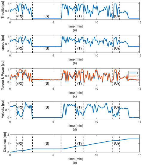
Figure 1.
Operational curves of a diesel LHD: (a) throttle position; (b) engine speed; (c) engine torque and power; (d) LHD velocity; and (e) traveled distance.

Table 1.
Base values are used for per-unit variables representation.
The four time segments marked in Figure 1 show characteristic behaviors related to specific operational conditions. The time segment (R) shows the case where the operator of the diesel LHD fully presses the throttle, increasing the engine speed, torque, and power while the LHD velocity is decreased. This behavior is characteristic of the bucket operation for load scooping in the extraction zone where one-step scooping demands high torque and power [22]. The time segment (S) is representative of the operational stops during which the operators must wait to access the dumping zone (ore pass) or must wait until the return route is available for safe transit. During this period, the engine speed stays in idle mode (around 750 rpm), as seen in Figure 1b. Segment (T) represents similar behavior to that described for (R) but with more intense acceleration movements needed to shake the bucket during dumping or to accommodate material for later loading into the bucket. The last time segment (U) is nearly equal to segment (R), with high engine acceleration in a short time resulting in a low LHD velocity. Figure 1d shows that the distance traveled by the LHD during the 15-min window is 1.52 km. It should be noted that the distance traveled between the end of (R) and the beginning of (S) is approximately 190 m, being very similar to the distance between the end of (U) and the next stop stage, demonstrating that the case studied has a cyclical behavior commonly found in LHD mining routes.
Then, the extended dataset of variables shown in Figure 1, was used to evaluate the proposed full-electric LHD model based on field measurements, considering a maximum capacity of 14 tons.
3. Full-Electric LHD Model
Figure 2 shows a general schematic of the proposed full-electric LHD model. The model is composed of an electric drive that includes an induction motor controlled by an indirect-vector-control topology [23]. The electric drive generates the power required to feed the powertrain composed of the mechanical pieces of the LHD that deliver power to the drive wheels. The powertrain characterization enables the implementation of the dynamic load model to provide both the total inertia of the electric LHD and load torque. Total inertia is required for tuning of the control law of the electric drive while load torque acts as a disturbance input to the electric drive, defining the acceleration characteristics of the LHD.
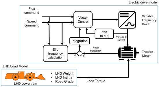
Figure 2.
Full-electric LHD general schematic.
The first stage of the full-electric LHD modeling starts with defining and analyzing the load model, considering the mechanical parameters, forces, and drag coefficients during operation.
3.1. LHD Load Model
This study was based on a commercial full-electric LHD (Sandvik, LH514-E), whose main technical specifications are presented in Table 2. Figure 3 shows the free-body diagram of all the forces acting over the LHD and the main wheel dimensions used to calculate the wheel and rim inertia.
Table 2.
Technical specification of LHD model LH514-E.
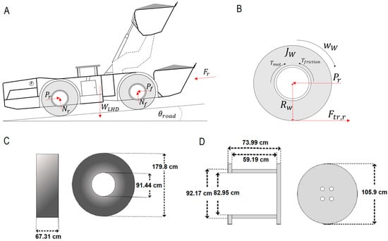
Figure 3.
(A) LHD free-diagram body; (B) traction wheels; (C) tire dimensions; (D) rim dimensions.
3.1.1. Inertial Components
In this section all the inertial components of the powertrain are calculated, considering the moments of inertia of the tires, rims, LHD structure, and LHD load [21]. The LHD model uses 26.5 × 25 L5S 36-ply tires, as indicated in Table 2. In this nomenclature, the first number refers to tire width, and “L5S” refers to the fact that it has an extra-deep tread which is ideal for working in very aggressive rocky areas. The last term (36 ply) refers to the thickness of the rim in inches (in). Figure 3C shows the approximate size of the LHD tire, whose mass is around 450 kg, while Figure 3D shows the approximate size of the tire rim in cm.
The inertia of the tire can be calculated based on the tire dimensions and then dividing the tire into three bodies: two hollow discs and one cylindrical shell (cs subscript).
Thus, the tire inertia is calculated by the sum of three components as follows:
where Adisc1 and Adisc2 are the areas of tire discs (m2), De is the external diameter of the tire (m), Di is the internal diameter of the tire (m), Asc is the area of the cylindrical shell (m2), W is the tire width (m), and Atire is the total area of the tire (m2). Then, with the mass of the tire already known, the tire inertia is determined as follows.
where mdisc1 and mdisc2 are the tire disc masses (kg), mtire is the tire mass (450 kg), and Jtire is the total inertia of the tire (kgm2). Then, the approximate inertia of the rim is estimated, considering an iron density of 7874 kg/m3 which results in a rim mass of 1302.6 kg.
With the mass of the rim and its dimensions, the inertia of the rim is determined considering three bodies: a hollow disk, a solid disk, and a hollow cylinder. The volume of the bodies is calculated as follows,
where Vhd, Vsd, and Vhc are the volumes of the hollow disc, solid disc, and hollow cylinder, respectively (m3), de and di are the external and internal diameters of the rim (m), and le and li are the external and the internal lengths of the rim (m). Then, the mass of the tire with the mass of the rim is determined considering that:
where mhd, msd, and mhc are the masses of the hollow disc, solid disc, and hollow cylinder, respectively (m), and ρiron is the iron density (kg/m3), then,
where Jhd, Jsd, and Jhc are the inertia of the hollow disc, solid disc, and hollow cylinder, respectively (kgm2), and Jrim is the total inertia of the rim. Subsequently, the inertia related to the translational movement of the LHD is estimated as:
where Rw is the tire radius (m), ngear is the gear ratio (dimensionless), mLHD and mload are the mass of the LHD and the material loaded, respectively (kg). The first term of the equation represents the inertia of the LHD without a load. Finally, the total inertia of the LHD is the sum of the translational inertia (Jtran), the motor inertia (Jmot), and the inertia of each tire and rim (Jtire, Jrim).
where JLHD is the total inertia of the LHD (kgm2). Then, the inertia of the LHD under no load conditions is 62.33 kgm2, while the inertia of the LHD considering a full load is 83.55 kgm2. In both cases, a planetary gearbox with a gear ratio ngear = 23.08 is used, considering that the motor rotates at 1396 rpm when the LHD velocity reaches 20.5 km/h.
3.1.2. Load Torque
According to [21] the equation that models the load torque by all the forces that act on a motorized vehicle with wheels depends on the air force, drag coefficients, the mass of the LHD, rolling coefficients, frontal area of the LHD, gravity, and road inclination. The following expression represents the load torque of the LHD:
Here, TLHD is the load torque reflected in the LHD motor (Nm) where ρa is the air density, va is the air velocity (m/s), vtire is the tire velocity (m/s), Cdrag is the drag coefficient (dimensionless), ALHD is the frontal area of the LHD (m2), mLHD is the LHD mass (kg), mload is the mass of the material carried (kg), g is the gravity force (m/s2), urr is the rolling coefficient (dimensionless), and θroad is the road inclination (%).
In the load torque equation, the air coefficient can be considered constant at an atmospheric pressure of 101 kPa and a temperature of 20 °C. The aerodynamic drag coefficient is considered to be 1.95, according to [24]. The frontal area of the LHD can be obtained from its dimensions as described in [25], considering a height of 2.545 m and a width of 2.897 m. The rolling coefficient used is the average value of those exposed in [26], which depends on the tire pressure and the LHD load. The inclination of the road will be equal to zero considering a horizontal route. Table 3 shows the values used for the load torque of the LHD.
Table 3.
Summary of parameters used to calculate the load torque.
To observe the influence of the mass of the material carried in the bucket of the LHD Figure 4 shows the load torque obtained considering different load masses as a function of the traveled distance, considering a flat route and a rolling coefficient of 0.03. Initially, the bucket is empty (0 t before loading), then after 5 km, the load is incremented to 7 t (loaded) until the 10 km where the bucket is unloaded remaining with 0.14 t. Then, after 15 km, the bucket is fully loaded with 14 t. Figure 4 shows that the load torque is slightly higher than 500 Nm when no load is carried in the bucket, while for full load conditions, the load torque reaches around 685 Nm.
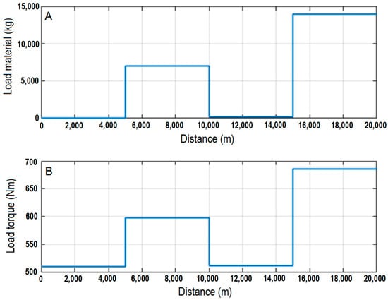
Figure 4.
(A) Material loaded in the bucket; and (B) load torque response.
According to equation 19, the LHD speed is another variable that influences the load torque. Figure 5 shows the load torque calculated when considering different motor speeds, which results in different LHD velocities. In the figure, the load torque is 664 Nm when the LHD operates at zero speed considering the effect of a constant wind speed of 2.78 m/s added to the torque component associated with the LHD mass with no load in the bucket. Then, the motor speed is incremented in successive ramps followed by steady speeds that, for instance, reach 272.5 rpm at 1000 m and 1396 rpm at 10,000 m. The load torque developed at those points is 666.9 Nm and 686 Nm, respectively, showing a lower variation when compared with the effect of mass increments (Figure 4) over the load torque.
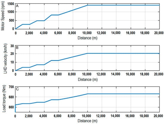
Figure 5.
(A) engine rotation speed; (B) LHD velocity; and (C) load torque response.
3.2. Electric LHD Model
In this section, the inertia and load torque expressions obtained from the LHD load model are complemented with a dynamic model of the LHD electric drive to create and evaluate the full-electric LHD model.
As shown in Figure 2, the electric drive is composed of an induction motor, which provides the torque and speed for the LHD powertrain. Table 4 shows the technical parameters used to model the induction motor obtained by solving nonlinear equations derived from the motor equivalent circuit using regression algorithms as proposed in [27]. The power and speed for the LHD motor are assumed to be 132 kW and 1500, respectively, considering the LHD nameplate shown in Table 2.
Table 4.
Summary of parameters determined for the induction-motor model.
As shown in Figure 2, the induction motor is fed by a variable frequency drive (VFD) operating with indirect vector control considering decoupled speed and flux commands. Before implementing the vector control, it is necessary to perform a correct controller setting based on the frequency and phase-margin method. In this case, the crossover frequency of the flux and torque current controllers was set to 300 rad/s with an 86° of the phase margin. The speed controller was tuned considering a crossover frequency of 2 rad/s with a phase margin of 84°, while the flux controller considered a crossover frequency of 15 rad/s with 86° of phase margin.
Figure 6 shows the results of the speed command () and speed feedback (), torque current command (), and torque current feedback (), load torque and electric torque, and electric power and output power generated by the electric drive, considering a load torque given by the parameters of Table 3. In this evaluation, a commanded speed ramp of 15 s accelerated the motor from 0 rpm up to 95% of the rated speed, which is equivalent to an LHD velocity ramp from 0 km/h to 20.5 km/h considering the tire dimensions and a gear ratio of 23.08.
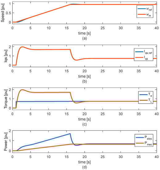
Figure 6.
Numerical evaluation of the electric LHD model: (a) speed command and motor speed; (b) torque current command and motor torque current; (c) electric and load torque; and (d) electrical and mechanical power.
Figure 6 shows that, at the end of the acceleration ramp (t = 16 s), the motor speed reaches 1396 rpm. As a result, the torque current command is increased above the rated value to increase the motor speed. It should be noted that the feedback current tracks the commanded signal with nearly zero tracking errors, showing a proper controller setting. Looking at Figure 6c, the electric torque has the same shape of , demonstrating an effective decoupled torque control during both dynamic and steady operation. During the acceleration stage (until t = 16 s), the electric torque increases above its rated value due to the significant inertia of the equipment that includes a loaded bucket. In Figure 6d, the electrical power of the LHD is significantly higher than the mechanical (output) power during the acceleration period. The mechanical power is obtained from the product between the load torque and speed while the electrical power is obtained by adding the internal losses of the induction motor to the mechanical power. Then, it can be inferred that the efficiency of the machine would tend to be lower during periods of acceleration; however, once the motor reaches steady operation this value would be close to 90%.
4. Electric LHD Model Based on Field Records
In this section, the Electric LHD model is evaluated considering the field record collected during the operation of a diesel LHD LH517 in an underground copper mine located in the central zone of Chile. Figure 7 shows the throttle, engine speed, engine torque and power, LHD velocity, and traveled distance during one hour of operation. The figure shows the evolution of these operational signals with clearly identifiable stops (at least six) of variable duration related to detentions where the operators wait to access the dumping zone or wait to return to the route after scooping or dumping. Here, the total traveled distance reaches 6.72 km. Despite the operational behavior, these field records can be used to assess the operation of the electric LHD model considering common work cycles developed in underground mines. The following section describes the field-signal selection and conditioning process required to evaluate the electric LHD model performance.
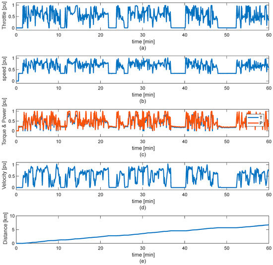
Figure 7.
Operational variables of LHD LH517 during one hour of work: (a) throttle position; (b) engine speed; (c) engine torque and power; (d) LHD velocity; and (e) traveled distance.
4.1. Signal Conditioning of Field Records
To evaluate the electric LHD model presented in Section 3, the engine speed and engine torque of the diesel LHD were conditioned to be used as speed reference () and load torque () inputs to the electric LHD model, respectively. Figure 8 shows the scheme of the field-record conditioning process. To obtain , the idle speed should be identified and subtracted from the engine speed. The idle speed is easily identified since it appears when the engine runs on, but the throttle position is zero representing the decoupling of the engine from the drivetrain. The disturbance input , is directly obtained from the engine torque signal of the diesel LHD and is integrated into the electric LHD model along with the total inertia.
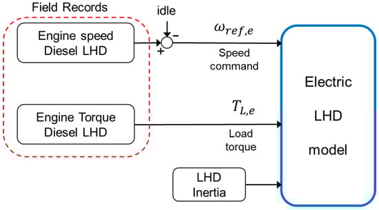
Figure 8.
Field-record conditioning for electric LHD model evaluation.
4.2. Evaluation of Electric LHD Model
Once the field records of the engine speed and torque were properly conditioned, as described in the previous section, the electric LHD model was evaluated for the same time window (one hour) considered in Figure 7. Figure 9 shows the resulting signals of the speed command () and speed feedback (), torque current command (), and torque current feedback (), load torque and electric torque, and electric power demanded by the electric drive. To compute the total energy consumed during the period under evaluation, the motor input power was also included in Figure 9e. Figure 9a shows that the commanded speed is properly conditioned by eliminating the idle component. The speed and torque current commands are tracked by the motor speed and motor current with nearly zero tracking error, confirming the proper tuning of the electric drive controllers. As expected, the electrical torque developed by the induction motor is higher than the load torque during the acceleration periods while during the deceleration periods, the electrical torque is lower than the load torque, even reaching negative values that represent the regenerative operation of the electric LHD (Figure 9c). As a result, the power demanded by the electric drive shown in Figure 9d reaches peaks close to the rated power (1 p.u.) as well as negative values during regenerative operation. Figure 9e shows the energy demand of the electric LHD model during the evaluated period of one hour. This energy profile was obtained assuming that the operation of the hydraulic pump is contained in the load torque signal used to evaluate the electric LHD model. Additionally, to include the energy demand of the ventilation system, the energy computation considered a constant demand of 3.0 kW added to the motor power shown in Figure 9d during the period evaluated. With these considerations, the base value used to compute the total energy consumed by the electric LHD is 180 kW, which represents the sum of the induction motor, hydraulic pump, and ventilation-system-rated power. Based on these considerations, the total energy consumed by the electric drive at the end of the evaluation period reached 86.8 kWh.
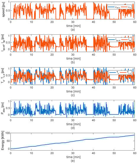
Figure 9.
Evaluation of the electric LHD model based on the field records: (a) speed command and motor speed; (b) torque current command and motor torque current; (c) electric and load torque; (d) electric power; and (e) consumed energy.
The last evaluation compares the energy consumption between the electric LHD model to an equivalent diesel LHD. The energy consumption of the diesel LHD was obtained from the field records of diesel demand during one hour of operation of the LHD model LH517, with a load capacity of17 tons. The equivalent diesel consumption for a 14-ton capacity LHD was obtained using a ballpark figure by direct scaling of the diesel-demand signal with the load-capacity ratio (14/17). Figure 10a shows the estimated diesel demand for the 14-ton LHD, while Figure 10b shows the total diesel consumption obtained by direct integration of the diesel demand, considering the same one-hour operation period previously evaluated. Figure 10c compares the energy demand for the electric LHD and the diesel LHD. For the computation of diesel LHD energy demand, it was considered that diesel fuel has a specific energy of around 38 MJ per liter, equivalent to 10.6 kWh/L.
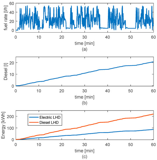
Figure 10.
Analysis of energy consumption of electric and diesel LHD: (a) diesel-demand rate; (b) diesel demand; and (c) energy consumed by the electric and diesel LHD.
Figure 10c shows that the diesel LHD has a much higher power consumption than the electric LHD. At the end of the evaluated operating hour, the electric LHD presents an energy consumption of 86.8 kWh, while the diesel LHD presents an energy consumption of 219.7 kWh. Therefore, the electric LHD saved 60.5% of energy compared with the diesel LHD for the hour of operation. This difference is mainly due to the low efficiency of diesel technology, which has significant heat losses that should be dissipated to the environment by radiators. Although in Chapter 4 the dynamic model of the gearbox was not considered due to its complexity, the gearbox efficiency for electric drivetrains ranges between 90% to 98% [28]. On the other hand, the electric LHD presents much greater energy efficiency, higher than 80%, if the power converter and motor efficiencies are combined.
5. Conclusions
Although there is a current growing tendency towards incorporating electrical equipment in different industrial processes, hybrid and/or electric LHD technologies are not yet in high demand in underground mining, despite the variety of options available today. In the case of electric LHDs, this is probably mainly due to the limitations imposed by the trailing cable, or the limited-range battery packs. However, it is expected that the replacement of diesel-powered machines with their electrical counterparts will enable benefits such as exhaust gas reduction and a reduction of operational costs.
In this study, it was possible to characterize the work cycles of a diesel LHD in an underground mine in central Chile. This valuable information was used to propose a methodology that allows for the evaluation of the performance of an electric LHD based on field records already available for diesel equipment. The proposed methodology begins with the definition of the dynamic model of the electric LHD, which is the result of the integration of a detailed load model that provides the operational inertia and load torque with a vector-control electric drive.
Unlike the diesel LHD, the evaluation shows that the electric LHD can regenerate energy that contributes to the energy efficiency of the process, which results in power requirements 60.5% lower than the diesel LHD during one hour of continuous operation, representing significant energy savings. Thus, the proposed methodology represents a valuable tool for operators and process engineers to project the energy requirements for the adoption of battery or trailing-cable electric LHDs, based on the current and historical operational data of diesel LHDs.
Author Contributions
Conceptualization, G.R. and G.F.; methodology, G.R. and G.F.; validation, G.R., R.G. and K.S.; resources, G.R., K.S. and K.Z.; writing—original draft preparation, G.R. and R.G.; writing—review and editing, K.S. and K.Z.; visualization, G.R., R.G. and G.F. All authors have read and agreed to the published version of the manuscript.
Funding
This research was funded by AGH University of Science and Technology in Poland, scientific subsidy under number: 16.16.100.215, and Universidad Católica de la Santísima Concepción in Chile, project CIBAS-511317.
Data Availability Statement
Not applicable.
Conflicts of Interest
The authors declare no conflict of interest.
References
- Flores, G. Future challenges and why cave mining must change. In 3rd International Symposium on Block and Sublevel Caving; Castro, R., Ed.; Universidad de Chile: Santiago, Chile, 2014; pp. 23–52. [Google Scholar]
- Salama, A.; Greberg, J.; Skawina, B.; Gustafson, A. Analyzing energy consumption and gas emissions of loading equipment in underground mining. CIM J. 2015, 6, 179–188. [Google Scholar] [CrossRef]
- Halim, A.; Lööw, J.; Johansson, J.; Gustafsson, J.; van Wageningen, A.; Kocsis, K. Improvement of Working Conditions and Opinions of Mine Workers When Battery Electric Vehicles (BEVs) Are Used Instead of Diesel Machines—Results of Field Trial at the Kittilä Mine, Finland. Min. Metall. Explor. 2022, 39, 203–219. [Google Scholar] [CrossRef]
- Varaschin, J.; De Souza, E. Economics of diesel fleet replacement by electric mining equipment. In Proceedings of the 15th North American Mine Ventilation Symposium, Blacksburg, VA, USA, 20–25 June 2015; Volume 8. [Google Scholar]
- Tuck, M. Mine Ventilation. In SME Mining Engineering Handbook, 3rd ed.; Darling, P., Ed.; SME: Plymouth, MA, USA, 2011; pp. 1577–1594. [Google Scholar]
- Michael, D.A.; Patricia, L.S.; Jay, H.L.; Aaron, B.; Patricia, A.S.; Roel, V.; Joseph, B.C.; Debra, T.S. The Diesel Exhaust in Miners Study: A Cohort Mortality Study with Emphasis on Lung Cancer. J. Natl. Cancer Inst. 2012, 104, 869–883. [Google Scholar] [CrossRef]
- Jacobs, W.; Hodkiewicz, M.R.; Bräunl, T. A cost–benefit analysis of electric loaders to reduce diesel emissions in underground hard rock mines. IEEE Trans. Ind. Appl. 2014, 51, 2565–2573. [Google Scholar] [CrossRef]
- Gleeson, D. Komatsu brings hybrid drive, narrow vein LHDs to Australian hard-rock market. Int. Min. 2021, 129, 120–134. [Google Scholar] [CrossRef]
- Epiroc. Scooptram ST7 Battery. 8. 2022. Available online: https://www.epiroc.com/es-es/products/loaders-and-trucks/electric-loaders/scooptram-st7-battery (accessed on 15 March 2023).
- Fiscor, S.; Jensen, J. The Best of MINExpo 2021. Eng. Min. 2021, 222, 42–53. Available online: https://www.proquest.com/docview/2604092726?pq-origsite=gscholar&fromopenview=true (accessed on 15 March 2023).
- Sandvik. Sandvik LH518B—Battery Electric Loader. 8. 2021. Available online: https://www.rocktechnology.sandvik/en/products/underground-loaders-and-trucks/battery-electric-loaders-and-trucks/lh518b-battery-electric-loader/ (accessed on 15 March 2023).
- Nieto, A.; Schatz, R.; Dogruoz, C. Performance analysis of electric and diesel equipment for battery replacement of tethered LHD vehicles in underground mining. Min. Technol. 2020, 129, 22–29. [Google Scholar] [CrossRef]
- Grycan, W. Electric Vehicles in Mining for the Aspect of Operational Safety. Prz. Elektrotechniczny 2022, 110–113. [Google Scholar] [CrossRef]
- Katta, A.K.; Davis, M.; Kumar, A. Assessment of greenhouse gas mitigation options for the iron, gold, and potash mining sectors. J. Clean. Prod. 2020, 245, 118718. [Google Scholar] [CrossRef]
- Rojas, G. Introducción de un LHD Híbrido a la Industria Minera y sus Posibilidades en el Mercado Chileno. Bachelor’s Thesis, Universidad de Chile, Santiago, Chile, 2017. [Google Scholar]
- Wolff, J.; Gómez, G. The Switched Reluctance Motor—An electric motor with high torque and small volume. Energía 1997, 4, 113–115. (In Spanish) [Google Scholar]
- Schultz, J.W.; Huard, S. Comparing AC Induction with Permanent Magnet Motors in Hybrid Vehicles and the Impact on the Value Proposition; Parker Hannifin Corporation: Cleveland, OH, USA, 2013. [Google Scholar]
- Hamouda, M.; Al-Amyal, F.; Odinaev, I.; Ibrahim, M.; Számel, L. A Novel Universal Torque Control of Switched Reluctance Motors for Electric Vehicles. Mathematics 2022, 10, 3833. [Google Scholar] [CrossRef]
- Krause, P.C.; Wasynczuk, O.S.; Sudhoff, D. Analysis of Electric Machinery and Drive Systems; John Wiley & Sons: Hoboken, NJ, USA, 2002. [Google Scholar]
- Ramirez, G. Control of Electric Drives; Universidad Católica de la Santísima Concepción: Concepción, Chile, 2017. (In Spanish) [Google Scholar]
- Valenzuela-Cruzat, J.; Valenzuela, M.A. Integrated Modeling and Evaluation of Electric Mining Trucks During Propel and Retarding Modes. IEEE Trans. Ind. Appl. 2018, 54, 6586–6597. [Google Scholar] [CrossRef]
- Meng, Y.; Fang, H.; Liang, G.; Gu, Q.; Liu, L. Bucket Trajectory Optimization under the Automatic Scooping of LHD. Energies 2019, 12, 3919. [Google Scholar] [CrossRef]
- Ramírez, G.; Valenzuela, M.A.; Pittman, S.; Lorenz, R.D. Modeling and Evaluation of Paper Machine Coater Sections Part 1: 1-Coater Section and Tension Setpoints. IEEE Trans. Ind. Appl. 2019, 55, 2144–2154. [Google Scholar] [CrossRef]
- Gillespie, T. Fundamentals of Vehicle Dynamics; SAE International: Warrendale, PA, USA, 2021. [Google Scholar]
- Sanvik. Optime Monitoring. 2022. Available online: https://www.rocktechnology.sandvik/optimine (accessed on 15 March 2023).
- Wicaksana, Y.; Widodo, N.P.; Kramadibrata, S.; Kresna, R. Determining rolling resistance coefficient on hauling road using dump-truck in open pit coal mine. In Proceedings of the International Symposium on Earth Science and Technology, Fukuoka, Japan, 6–7 December 2011. [Google Scholar]
- Lee, K.; Frank, S.; Sen, P.K.; Polese, L.G.; Alahmad, M.; Waters, C. Estimation of induction motor equivalent circuit parameters from nameplate data. In Proceedings of the 2012 North American Power Symposium (NAPS), Champaign, IL, USA, 9–11 September 2012; pp. 1–6. [Google Scholar]
- Břoušek, J.; Zvolský, T. Experimental study of electric vehicle gearbox efficiency. In MATEC Web of Conferences; EDP Sciences: Les Ulis, France, 2018; Volume 234, p. 02004. [Google Scholar]


Disclaimer/Publisher’s Note: The statements, opinions and data contained in all publications are solely those of the individual author(s) and contributor(s) and not of MDPI and/or the editor(s). MDPI and/or the editor(s) disclaim responsibility for any injury to people or property resulting from any ideas, methods, instructions or products referred to in the content. |
© 2023 by the authors. Licensee MDPI, Basel, Switzerland. This article is an open access article distributed under the terms and conditions of the Creative Commons Attribution (CC BY) license (https://creativecommons.org/licenses/by/4.0/).