Review

Cryogenic Hydrogen Jet and Flame for Clean Energy Applications: Progress and Challenges

1
Zienkiewicz Centre for Computational Engineering, Faculty of Science and Engineering, Swansea University, Swansea SA1 8EN, UK
2
Fire and Explosion Modelling Group, School of Mechanical Engineering Sciences, University of Surrey, Guildford GU2 7XH, UK
*
Author to whom correspondence should be addressed.
Energies 2023, 16(11), 4411; https://doi.org/10.3390/en16114411
Submission received: 18 April 2023 / Revised: 11 May 2023 / Accepted: 25 May 2023 / Published: 30 May 2023
(This article belongs to the Special Issue Heat and Thermal Fluid Flow for Advanced Aerospace Propulsion)

Abstract

:
Industries across the world are making the transition to net-zero carbon emissions, as government policies and strategies are proposed to mitigate the impact of climate change on the planet. As a result, the use of hydrogen as an energy source is becoming an increasingly popular field of research, particularly in the aviation sector, where an alternative, green, renewable fuel to the traditional hydrocarbon fuels such as kerosene is essential. Hydrogen can be stored in multiple ways, including compressed gaseous hydrogen, cryo-compressed hydrogen and cryogenic liquid hydrogen. The infrastructure and storage of hydrogen will play a pivotal role in the realisation of large-scale conversion from traditional fuels, with safety being a key consideration. This paper provides a review on previous work undertaken to study the characterisation of both unignited and ignited hydrogen jets, which are fundamental phenomena for the utilisation of hydrogen. This includes work that focuses on the near-field flow structure, dispersion in the far-field, ignition and flame characteristics with multi-physics. The safety considerations are also included. The theoretical models and computational fluid dynamics (CFD) multiphase and reactive flow approaches are discussed. Then, an overview of previous experimental work is provided, before focusing the review on the existing computational results, with comparison to experiments. Upon completion of this review, it is highlighted that the complex near-field physics and flow phenomena are areas lacking in research. The near-field flow properties and characteristics are of significant importance with respect to the ignition and combustion of hydrogen.

1. Introduction

1.1. Background and Motivation

The theory of climate change has been studied for nearly 100 years, becoming increasingly apparent and worrying in recent years. Guy Callendar was the first to make the connection between rising atmospheric carbon dioxide levels and global warming on Earth, in 1938 [1]. In his 1938 published paper, it was highlighted that the combustion of fossil fuels by man was the key driving factor in the rising atmospheric carbon dioxide levels in the air. However, 84 years after Callendar’s first presented evidence, the climate crisis is only now starting to be treated with some level of urgency, despite the fact that the impact of climate change has been felt across the world, in the form of rising sea levels, heat waves, warming oceans and more frequent natural disasters. Recently, the United Nations held their 27th conference on climate change, known as COP27, in Sharm el-Sheikh, which concluded on 20 November 2022. This conference has placed further pressure on the countries of the world to ‘drastically’ reduce their emissions urgently. The transportation sector has been identified as one of the greatest contributors to global greenhouse gas emissions. This paper focuses on the transportation sector, particularly the aviation and aerospace industries.
The UK government has committed to decarbonising all sectors, including transport, and achieving ‘net-zero’ carbon emissions by 2050 [2]. Additionally, the UK government has gone further by proposing the earlier target of 2040 for the domestic aviation sector to reach net zero, as stated in the Jet Zero consultation [3]. In the summary of responses, hydrogen was identified as one of the favoured alternative fuels to kerosene for domestic flights. Moreover, within this consultation, it was stated that there was concern about the viability of current zero-emission flight technology and the timescale to continue development. This also included concern about the availability of green hydrogen, which is hydrogen that is generated through the use of renewable electricity. Nevertheless, further investment has been suggested by the UK government into the research and development (R&D) of zero-emission aircraft technology. It is evident that hydrogen will not only play a role in the future of the UK’s aviation sector, but in the entire transport sector, as stated in [4]. This document, published by the UK Department for Transport, highlighted that R&D funding will focus on green hydrogen to be used in the rail, maritime, aviation and heavy road freight sectors. Following this, in 2021, the UK government published an overarching strategy that focused on the increased production of hydrogen [5]. The proposed strategy covers aspects such as hydrogen production, storage, distribution, applications, the supply chain and economic benefits regarding the large upscaling of the hydrogen industry in the UK.
The UK clearly realises the potential for hydrogen and aims to be a world leader in the industry, but why hydrogen? Hydrogen is the most abundant element on Earth; it is a clean, renewable energy source. When hydrogen is combusted with oxygen, a large amount of energy is released, with water vapour being the only emission into the atmosphere. This is the primary reason that hydrogen is considered as the future of propulsion fuels, along with its high energy density. Hydrogen as a fuel is often stored in its liquid state, for ease of transportation. Liquid hydrogen (LH2) must be stored at extremely low cryogenic temperatures, at around 20 K (−253.15 °C). Further details of the general properties of liquid hydrogen can be found in [6] but are also further described in Section 1.2 of this paper, whereas Section 1.3 provides an overview of the different methods of hydrogen storage and the associated safety risks.
As previously mentioned, it is essential that the future large-scale uptake of hydrogen is satisfied through the production of ‘green hydrogen’. The large majority of hydrogen produced is generated using coal or natural gas. This type of production has a large carbon footprint and the hydrogen produced as a result is referred to as ‘grey hydrogen’. The use of grey hydrogen as an alternative transportation fuel would be illogical and would defeat the purpose of switching to a clean alternative. Grey hydrogen is much cheaper to produce than green hydrogen, which is why only approximately 2% of the global hydrogen production is green. There is another type of hydrogen that is known as ‘blue hydrogen’, generated when the carbon emissions from grey hydrogen are captured. Several cited papers offer an extensive review on hydrogen production, including both the renewable and fossil fuel methods in [7,8,9,10], and with [11] emphasising the key challenges involved.

1.2. The History of Hydrogen in the Aerospace Industry

This section highlights some of the key advancements made throughout history with respect to hydrogen technology in the aviation industry, which are visualised in Figure 1. The first use of hydrogen in aeronautics dates back to 1783 in France, when Jacques Charles and the Roberts brothers designed and flew the first manned hydrogen-filled balloon [12]. The balloon was capable of carrying two passengers and was approximately thirteen feet in diameter. The next major advancement in hydrogen aviation technology arose in 1874 with the first design of the Zeppelin, proposed by the German Count Ferdinand von Zeppelin [13]. The Zeppelin was a rigid type of airship that utilised hydrogen to produce buoyancy and allow the airship to float. The Zeppelin Company maintained a perfect safety record during the first 27 years of civil flights, until a catastrophic failure, which was the Hindenburg disaster of May 1937 [14]. The most common theory of the cause of the accident was that an electrostatic charge caused the ignition of a hydrogen gas leak from the balloon, causing the airship to burst into flames. There were a total of 35 fatalities among the 97 people onboard and a single fatality on the ground as a result. The Hindenburg disaster had a dramatic impact on the hydrogen industry, particularly in civil aviation, as it gained a public reputation for being dangerous and unsafe.
The next important breakthrough in hydrogen propulsion was Germany’s Heinkel Strahltriebwerke 1 (HeS-1) gas turbine jet engine, invented by Hans von Ohain. The HeS-1 was the first jet engine that ran on hydrogen, with stationary tests first being performed in 1937 [15]. Then, following the significant development of rocket technology in World War II by the Germans with their V-2 rocket, propulsion engineers revisited the potential of hydrogen. In the latter half of the 1940s, the United States was responsible for the significant enhancement of LH2 airplane and rocket fuel technology through military contracts [16]. This research provided initial data for theoretical studies about the properties of LH2 and early experimental results for a hydrogen–oxygen rocket. Later, in 1956, Pratt and Whitney conducted research into the use of LH2 as a fuel for turbojet engines. Aircraft flight tests were undertaken to obtain flight performance data, using a modified J-65 turbojet engine with a hydrogen supply system installed in a B-57 US bomber aircraft. The US Space program has since made use of LH2 in several rocket designs, notably including the Atlas [17], Saturn-IV and Apollo families of missiles and space launch vehicles.
In the late 1980s, the Soviet Union modified the Tupolev Tu-154 into an alternative fuel testbed, later named the Tu-155 [18]. The Tu-155 was first used to test liquid hydrogen by replacing one of the two traditional engines with one powered by hydrogen. The Tu-155 successfully completed its maiden flight, making a strong impression on the west, inspiring many modern projects to come. It was made clear that the main issue that Tupolev engineers had with hydrogen was storing it at as a liquid.
More recently, in 2000, the project CRYOPLANE was born, formed by a consortium of 35 European-Commission-funded partners. The project was led by Airbus Deutschland with the purpose of developing a fuel system capable of using LH2 for conventional aircraft. It was found that the required volume of LH2 was four times greater than that of a traditional aircraft fuel storage system [19]. There have also been many recent hydrogen-powered aircraft projects, including the HyShot [20] in 2001, NASA X-43 [21] in 2004 and the Phantom Eye [22] in 2013. In light of the current climate crisis, it is clear that there has been a significant resurgence in the development of hydrogen-powered aircraft and related research. The performance aspects of LH2 were compared to kerosene in [23]; Ref. [24] highlighted the associated emission reduction, and ref. [25] investigated the long-term viability of hydrogen and other alternative fuels, whereas ref. [26] compared hydrogen to various hydrocarbon fuels, an explanation of hydrogen fuel cell technology is provided in [27], an overview of modern aircraft propulsion can be found in [28], and, finally, ref. [29] provides a review on the challenges and opportunities of hydrogen as an aviation fuel.

1.3. Hydrogen Storage Methods

Hydrogen can be stored as a gas or liquid using physical storage tanks at high pressure and a very low temperature. The three main physical-based hydrogen storage methods are compressed gas tanks, cryo-compressed tanks and cryogenic liquid tanks. There are also material-based hydrogen storage methods, in which the hydrogen is either absorbed within a solid or stored on the surface of the solid. This section provides an overview of the physical-based storage methods only, as these are relevant to the contents of this review paper.
Compressed hydrogen gas storage refers to the physical storage of hydrogen in its gaseous state, at high pressures of around 350–700 bar [30]. This method of storage is the most common and mature of the three physical-based methods. According to [31], more than 80% of the world’s hydrogen refuelling stations in 2010 stored hydrogen using the compressed gaseous method. It is the cheapest method as the hydrogen is not cooled to very low cryogenic temperatures, meaning that less energy is required. However, the disadvantage is that hydrogen gas occupies a significantly larger volume than liquid hydrogen. For this reason, this method of storage is not practical for onboard applications where volume is a constraint. It is more suitable for the onsite storage of hydrogen at large ground storage stations.
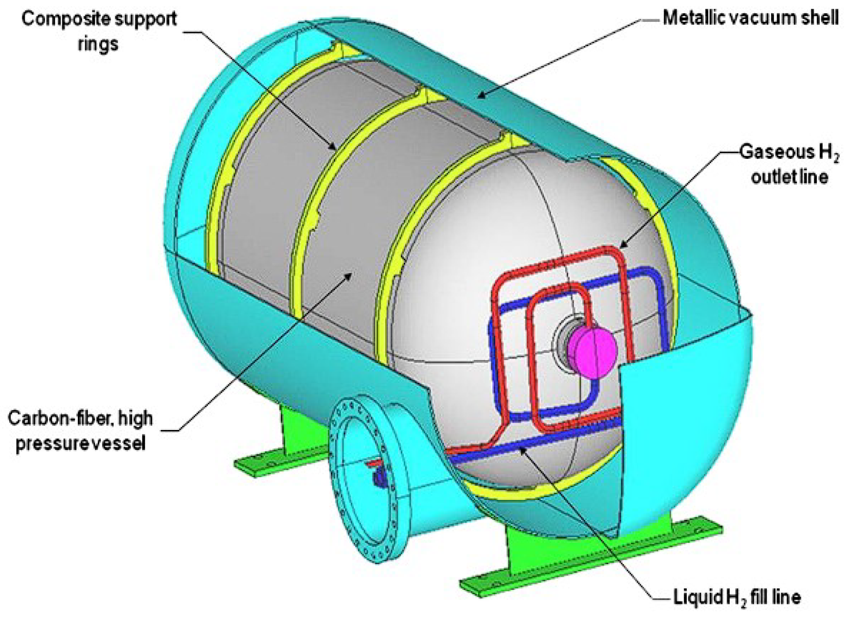
More recently, the introduction of supercritical cryo-compressed hydrogen storage has been developed [32,33]. In this concept, hydrogen is stored in a pressure vessel at very high pressures and cryogenic temperatures. However, no liquefaction is involved during this process so there are no evaporative losses, unlike in the storage of liquid hydrogen. This leads to a great reduction in power consumption when compared to LH2 storage. An example configuration of a cryogenic pressure vessel can be seen below in Figure 2 [34].
Whilst hydrogen has roughly three times the energy density per unit mass compared to gasoline, liquid hydrogen has an energy density per unit volume that is four times less than gasoline [26]. This means that liquid hydrogen requires a much larger storage tank volume for an equivalent amount of energy to gasoline. This would result in non-conventional fuel tank storage systems onboard aircraft, as suggested in [35]. Cryogenic liquid hydrogen storage is the most expensive method due to the large amount of electricity required to cool hydrogen below its boiling point. It has been estimated in theory that to produce 1 kg of LH2, approximately 4–10 kWh of energy is required [36]. However, liquid hydrogen has the most desirable storage properties out of each of the three described. As a result, it is applied in industries where performance takes priority over cost, such as the aerospace industry, for example.
The storage and transmission of hydrogen are very hazardous procedures, with many serious associated risks to be considered and studied. As indicated in [37], these include the accidental leakage of hydrogen from storage tanks, forming hydrogen jets. If these jets become ignited, hydrogen jet fires and potentially explosions can occur. The accidental release of liquid hydrogen can result in flash evaporation, which may be the cause of pool fires. Many studies have been undertaken to study these unignited and ignited hydrogen jets, with the aim to gain a better understanding of the flow and flame properties. Often, these jets are highly underexpanded and influenced by several complex compressible flow shock wave phenomena due to the high-pressure storage conditions. The following sections provide an overview of theoretical, experimental and numerical simulation studies on hydrogen jets and flames. Through these studies, a better understanding of the risks can be obtained, allowing predictive tools capable of quantifying these risks to be produced, e.g., the HyRAM toolkit [38]. Understanding these cryogenic hydrogen jet and flame mechanisms is also of great importance for the injection of hydrogen fuel through pinhole nozzles into combustion engines.

2. Physics and Theoretical Models

The aim of this section of the paper is to provide some background on the previously developed theoretical models, underlying physics, jet structures and flow phenomena. The way in which this theory and physics has been applied to hydrogen jets and flames is outlined in the following sections, in an overview of both experimental and numerical simulation studies.

2.1. The Underexpanded Jet

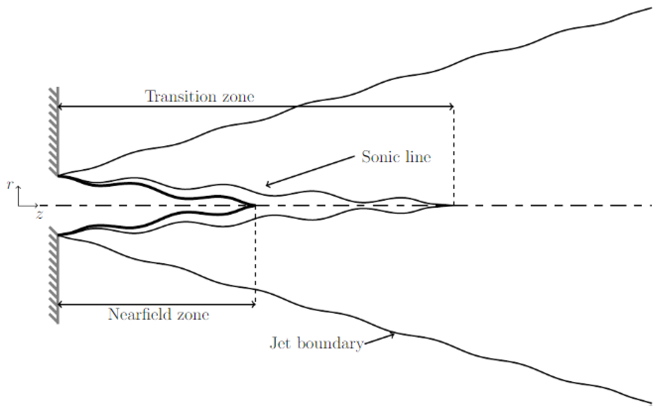
Firstly, when hydrogen is released from a high-pressure storage vessel, an underexpanded jet is formed. An underexpanded jet occurs when the exit pressure from a nozzle or hole is higher than the ambient pressure. The steady-state structure of an underexpanded jet is influenced by the viscous and compressibility effects of the fluid flow. Three main flow regions can be identified in the jet; these are the near-field, transition and far-field zones. These were described in great detail in a review paper that focused on general underexpanded jets [39]. A core flow region and mixing layer are present in the near-field zone of the jet. In this core flow part of the zone, compressible effects dominate the flow behaviour and properties. In the mixing layer, an exchange between the jet fluid and the surrounding fluid takes place due to the effects of turbulence. As the flow propagates downstream, the mixing layer replaces the inner core, marking the start of the transition zone. There are only small changes in the flow variables within the transition zone, which leads to the homogenisation of the pressure field. After the transition zone, the jet flow becomes fully expanded, marking the start of the far-field zone. In the far-field zone, compressibility effects may still occur but they do not dominate the flow. The flow in this region can be described as a classical jet. Figure 3 below provides an illustration of the location of each of the three flow zones in an underexpanded jet, as found in [39].
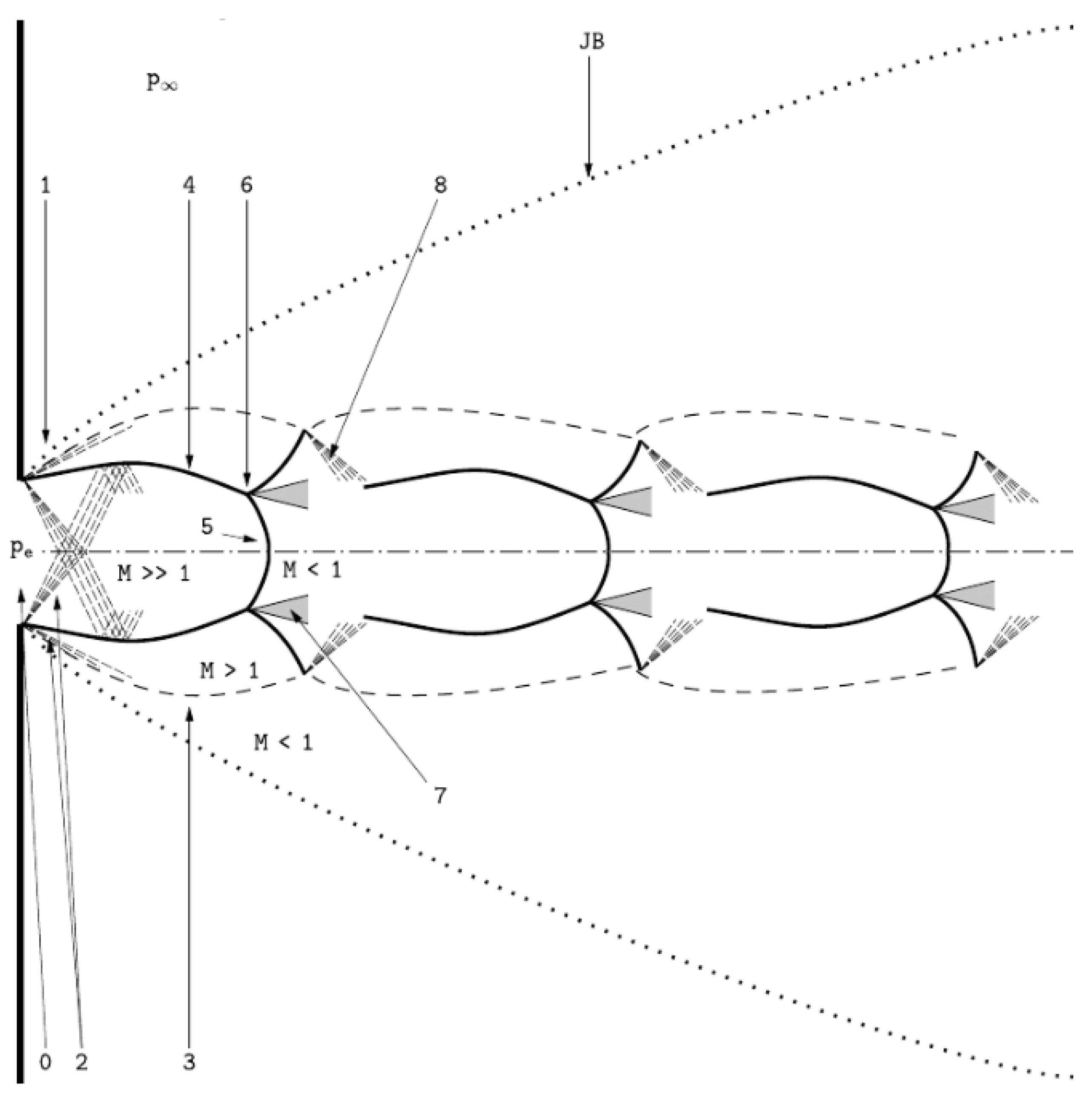
The majority of the studies undertaken on hydrogen jets and flames focused on the far-field zone in particular, as they were interested in quantifying the safety risks. Measurements of the flame lengths, hazard distances and thermal doses can be obtained by studying the far-field zone. Additionally, the far-field region is less complex to model when compared to the near-field zone. The structure of the near-field jet shock system can be categorised into three cases: moderately underexpanded, highly underexpanded and very highly underexpanded. The parameter known as the nozzle pressure ratio (NPR) is used in this categorisation. The NPR is the ratio of the nozzle exit pressure or total state to the ambient pressure. A moderately underexpanded jet occurs, with air, when the NPR is between 1.1 and 3 [40]. The resulting shock wave structure can be seen below in Figure 4, as described in [39].
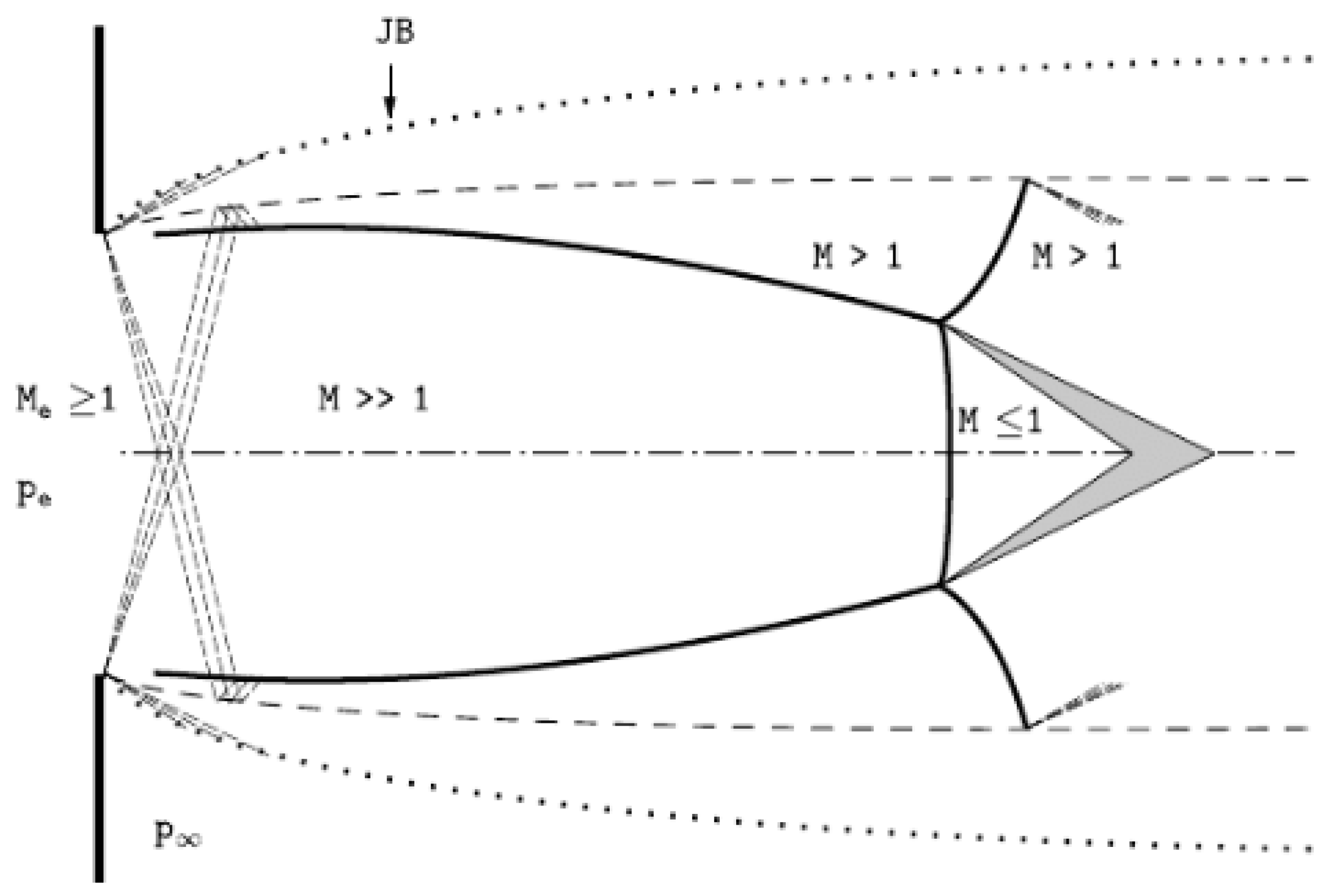
The structure of a highly underexpanded jet can be seen in Figure 5, and it occurs when the exit pressure is increased to an NPR between 2 and 4 [41]. Finally, for a very highly underexpanded jet, the shock structure can be seen in Figure 6. A highly or extremely underexpanded jet occurs when the NPR is greater than or equal to 3 [42].

2.2. Hydrogen Jet Theoretical Studies

Theoretical predictive models specific to the modelling of cryogenic hydrogen jets and flames have also been developed, under both ignited and unignited conditions. The sudden release and formation of hydrogen jets from high-pressure storage vessels has been researched theoretically many times, through studies of varying complexity. Some of these are described in this section.
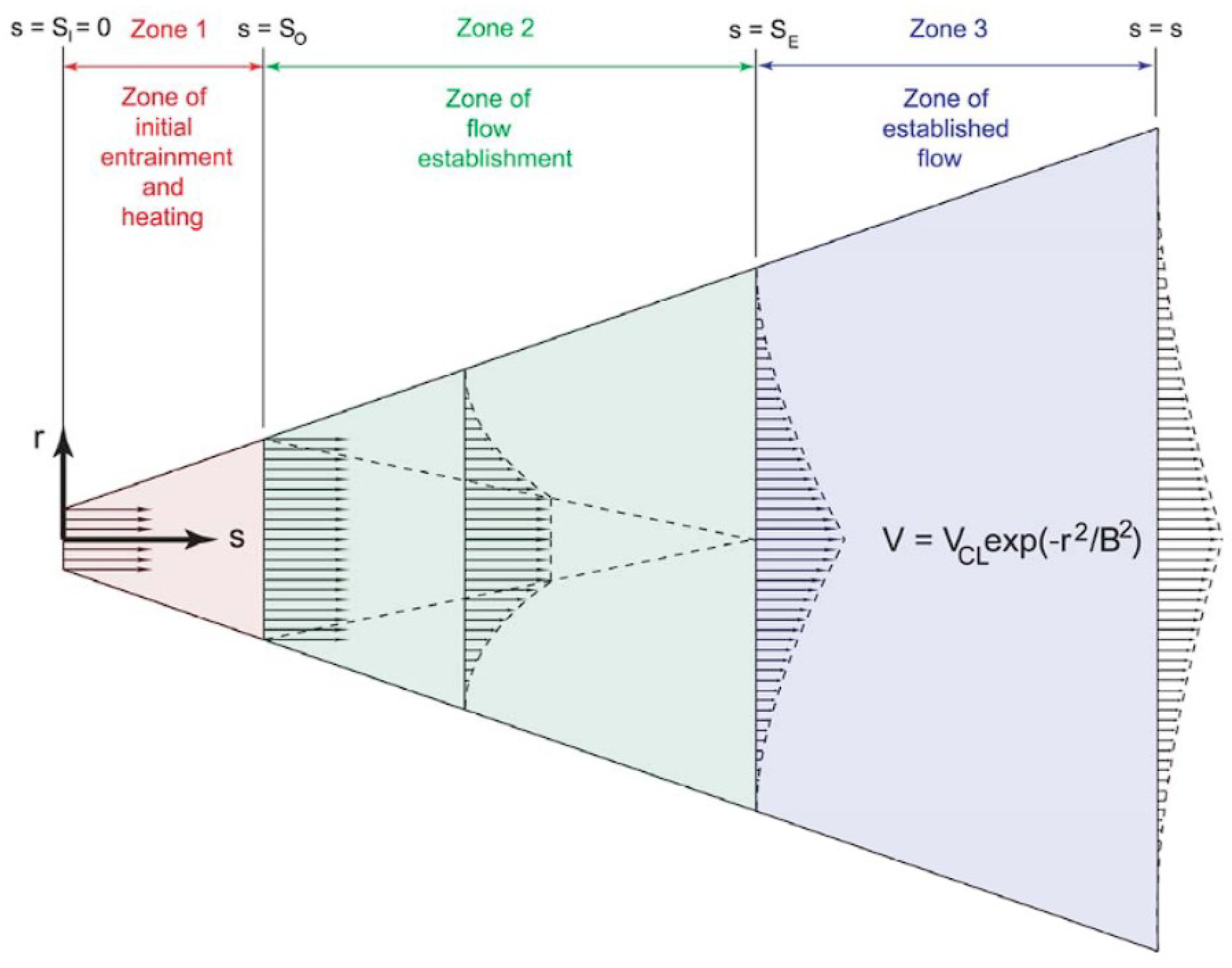
In 2009, the Sandia National Laboratories (SNL) in the United States published a theoretical paper on the modelling of intended and unintended liquid hydrogen leaks from storage systems [43]. An equilibrium-based Gaussian entrainment model was proposed in this report that can be used to predict the properties and trajectory of the resulting hydrogen jet. There were two different leaking conditions studied; these were named ‘slow’ and ‘fast’. Slow leak modelling referred to leaks that occurred due a microscopic crack in the storage vessel. The fast leak model focused on releases through comparably large holes. The slow leak system scenario is visualised in Figure 7 below, from [43].
In this model, it was assumed that the flow was quasi-steady state, the hydrogen exit pressure was equal to atmospheric pressure, and there were negligible potential and kinetic energy changes in the flow stream and an assumed adiabatic flow. A set of three turbulent entrainment models was developed to predict the flow in different zones of the leak, as displayed in Figure 8. In Zone 1, air entrains into the pure hydrogen, forming a mixture as it undergoes heating from its initially cold temperature. The effect of buoyancy is neglected in this zone as it is very short, especially in comparison to the following two zones. The second zone represents the transition region from the zone of initial entrainment to the final zone of the established flow. It can be seen in Figure 8 that the flow profile transitions from a uniform to a Gaussian profile in this zone.
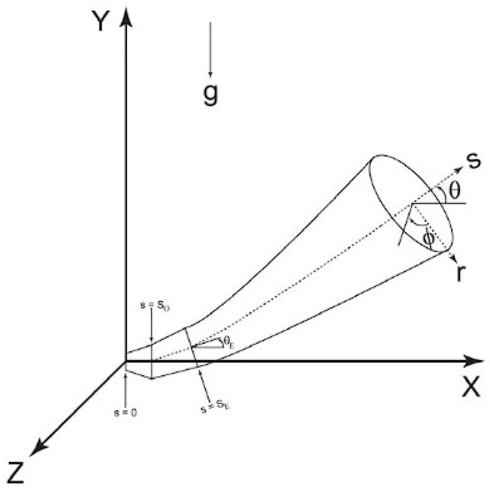
Finally, the Gaussian flow profiles become fully established in Zone 3. This zone is the longest of each of the regions, with buoyancy influencing the jet. The coordinate system adopted to describe the trajectory of the jet influenced by buoyancy in Zone 3 is demonstrated in Figure 9. For specific details of the models and equations for each slow leak zone, the cited report can be referred to.
Additional work and results on slow leak modelling were further presented by Winters and Houf in an article in the following year [44]. The predicted states of the hydrogen and hydrogen–air mixture were presented for Zones 1 and 2. These values were then used as the starting point for Zone 3, where the established flow models were implemented into a computer code named COLDPLUME. COLDPLUME was developed by Houf and Schefer [45] and was used to predict the flow characteristics, such as the maximum radial distances from the leak origin, for both saturated liquid and vapour leaks. The dilution profiles and trajectories were also presented in [43,44].
The ‘fast’ leak system is visualised in Figure 10 below, from [43]. The key assumptions made in the fast leak model were that the leak flows were quasi-steady, the total pressure loss from the stagnation to exit conditions was negligible, and there were negligible potential energy changes, thermodynamic equilibrium, a homogeneous two-phase flow, a uniform temperature and pressure in the tank contents and negligible heat exchange between the flow and tank. The author developed a program in Fortran named FLASHEXIT1, which was used to determine the state and velocity of hydrogen at the leak exit during a fast leak; the algorithm can be seen in [43]. The exit quality, mass flux, mach number, temperature and pressure were plotted as a function of storage pressure for fast leaks from both the saturated liquid and vapour phases. Through the analysis of these results, it was noted that the fast leak flows become choked. As a result of this, a supersonic flow will develop downstream of the choke, causing the formation of an underexpanded jet shock structure, as previously described. A model known as the ‘Mach Disk Model’ was used to compute equivalent two-phase downstream atmospheric conditions, originally proposed by Winters and Evans [46]. Using this model, the resulting mach disk area, mach number, mass flux, flow velocity, temperature and quality were calculated as a function of storage pressure, as seen in [43]. The SNL carried out further theoretical study into the simulation of high-pressure liquid hydrogen release, publishing an additional, slightly more complex model in 2013, as found in [47]. This model focused on high-momentum hydrogen leaks, splitting the flow into five different zones. The model was implemented to compute the hydrogen dilution distances to the lower flammability limit. It was found that saturated vapour leaks had the shortest dilution distances, when compared to saturated liquid and sub-cooled liquid leaks.
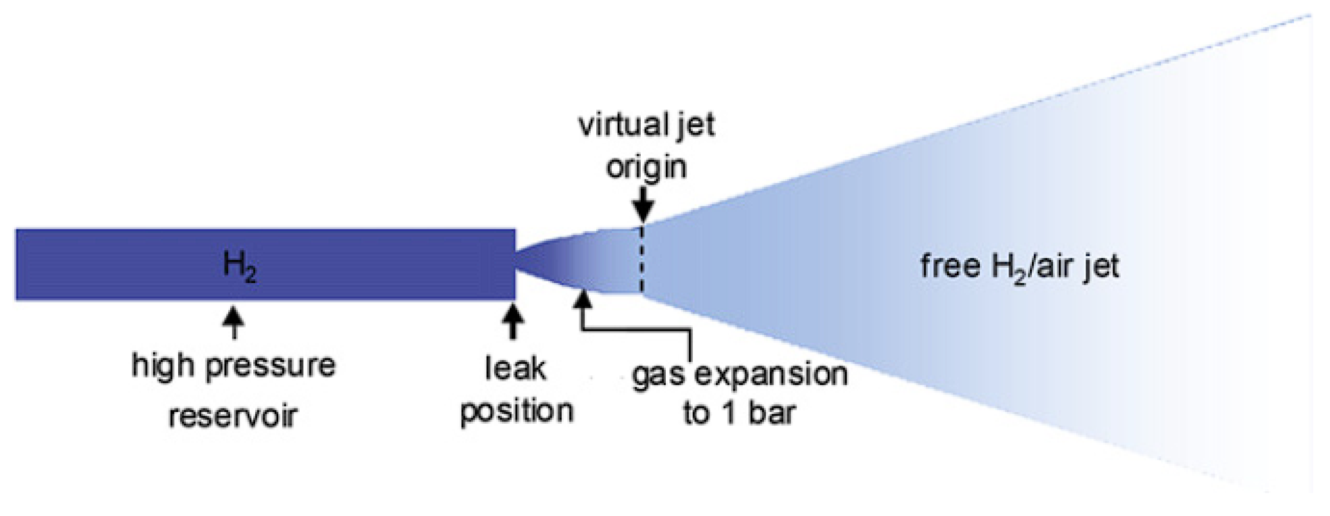
An additional series of theoretical models for the prediction of gaseous hydrogen jet properties due to a small leak from a high-pressure pipeline was introduced by Xiao, Travis and Breitung [48] in 2010. Similarly to the previous model, the flow regimes were broken down into three phases or zones. These were the initial release of gaseous hydrogen from a high-pressure reservoir, the adiabatic expansion to atmospheric pressure and, finally, the free established hydrogen gas jet from the virtual jet origin. The breakdown of these phases is visualised in Figure 11 below, reproduced from [48]. In the first phase, a real-gas equation of state was coupled with an isentropic expansion model to predict the gas state within the reservoir and at the leak position. Then, a zero-dimensional model was implemented to model the second phase, in which the gas expands to 0.1 MPa. Finally, for the developed free hydrogen gas jet, an integral model was newly proposed. These models can be seen in [48], along with resulting predictions of the gas properties at each phase and concentration, velocity, temperature, flammable length, width and volume for the established free hydrogen jet phase. These models were validated and compared against similar experiments, showing very good agreement between the sets of results.
Petitpas and Aceves also produced a theoretical model to address sudden hydrogen expansion from a cryogenic pressure vessel [34], for an initial temperature range of 27 to 400 K and pressure of up to 1210 bar. The model involves single- and two-phase flow equations, coupled with a real gas equation of state, such as the Beattie–Bridgman or Abel–Noble equations. In this study, the release of hydrogen from both compressed gaseous and cryogenic liquid storage vessels was presented, allowing for a comparison of the results. It was concluded that cryogenic storage offers potential advantages in terms of safety when compared to compressed gaseous storage. This is due to the working temperature being much lower, meaning that the released hydrogen has less energy. Moreover, the hydrogen releases into an intermediate chamber first and the vacuum jacket protects the vessel from environmental damage. This intermediate chamber and jacket are visualised in the schematic of the cryogenic pressure vessel in Figure 12, from [34]. It was found that the thrust of hydrogen release from a cryogenic tank was up to 10 times lower than that of hydrogen leaks from traditional compressed gaseous vessels.
Some recent examples of hydrogen jet theoretical models and studies can be found in the citations [49,50,51,52].

3. Overview of Experimental Studies

In this section of the review paper, a series of cryogenic hydrogen experiments undertaken at different test facilities across the world are discussed, including the numerous studies undertaken by Sandia National Laboratories (SNL) in the United States, the Karlsruhe Institute for Technology (KIT) in Germany, the New Energy and Industrial Technology Development Organization (NEDO) in Japan, the United Kingdom Health Safety Laboratory (HSL), the National Aeronautics and Space Administration (NASA) in the United States and many others. It is shown in the following sections that many of these described experiments can be used to validate the numerical studies on cryogenic hydrogen jets and flames.

3.1. Sandia National Laboratories (SNL)

Sandia National Laboratories operates as a contractor for the United States government and is a federally funded research and development center. SNL carries out research into a broad range of topics within engineering, science and technology and has done so for more than 70 years. Energy is one of the four main strategic areas of the research that is undertaken by SNL, which includes research into hydrogen at the SNL Combustion Research Facility in California.
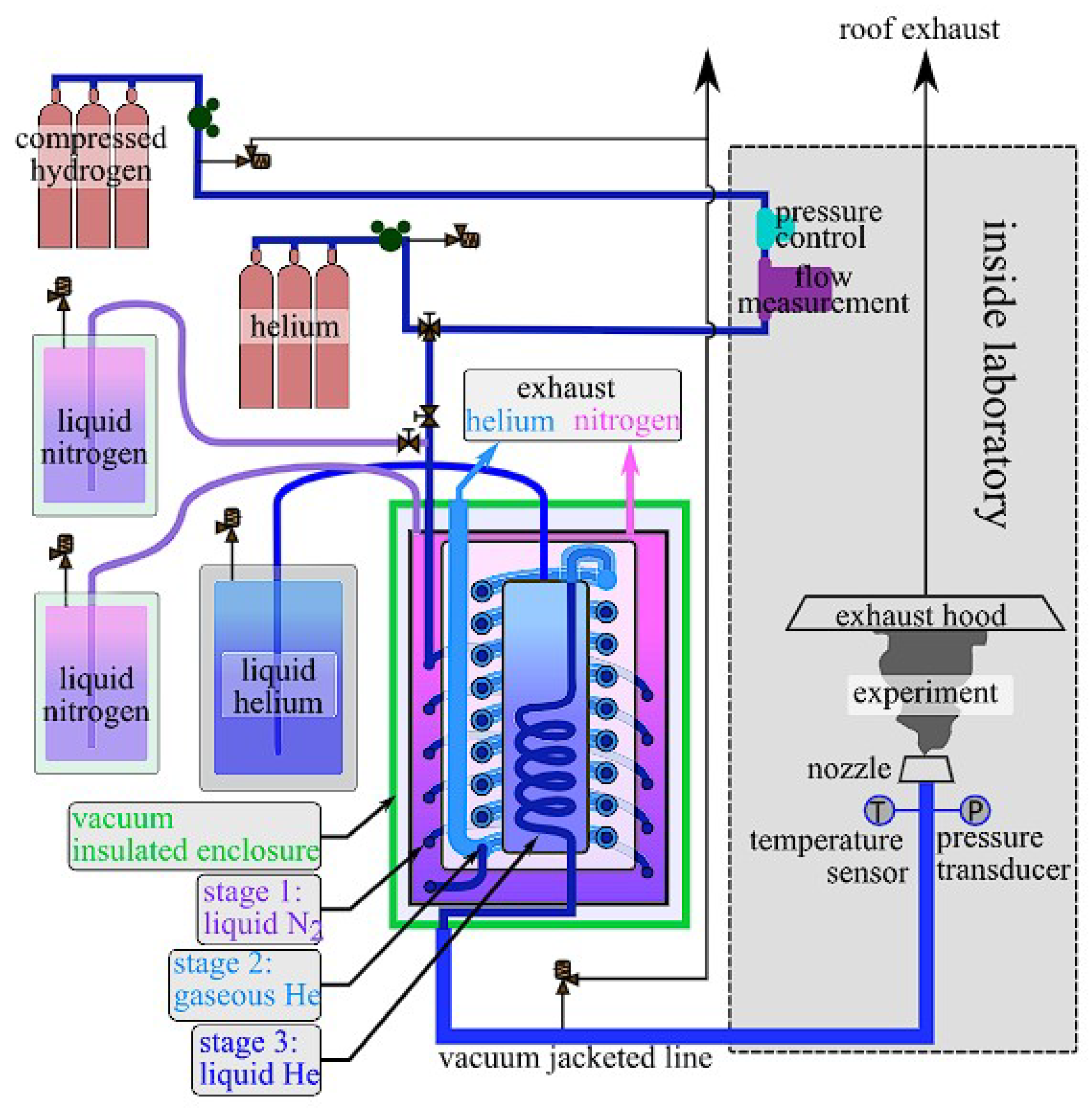
In 2017, Hecht and Panda of SNL carried out experiments at the Turbulent Combustion Laboratory to investigate the ignition and flame characteristics of cryogenic hydrogen jets [53]. The experiment was designed to simulate an ignited release from a fairly low-pressure liquid hydrogen storage tank at the saturated liquid temperature, using a laser spark for ignition. The experimental system used in this study is displayed in Figure 13, from [53]. The maximum ignition distance, flame length and radiative heat flux were measured for a range of nozzle exit temperatures (37–295 K), pressures (2–6 bar), LH2 mass flow rates (0.1–0.7 g/s) and release diameters (0.75–1.25 mm) in the experiments.
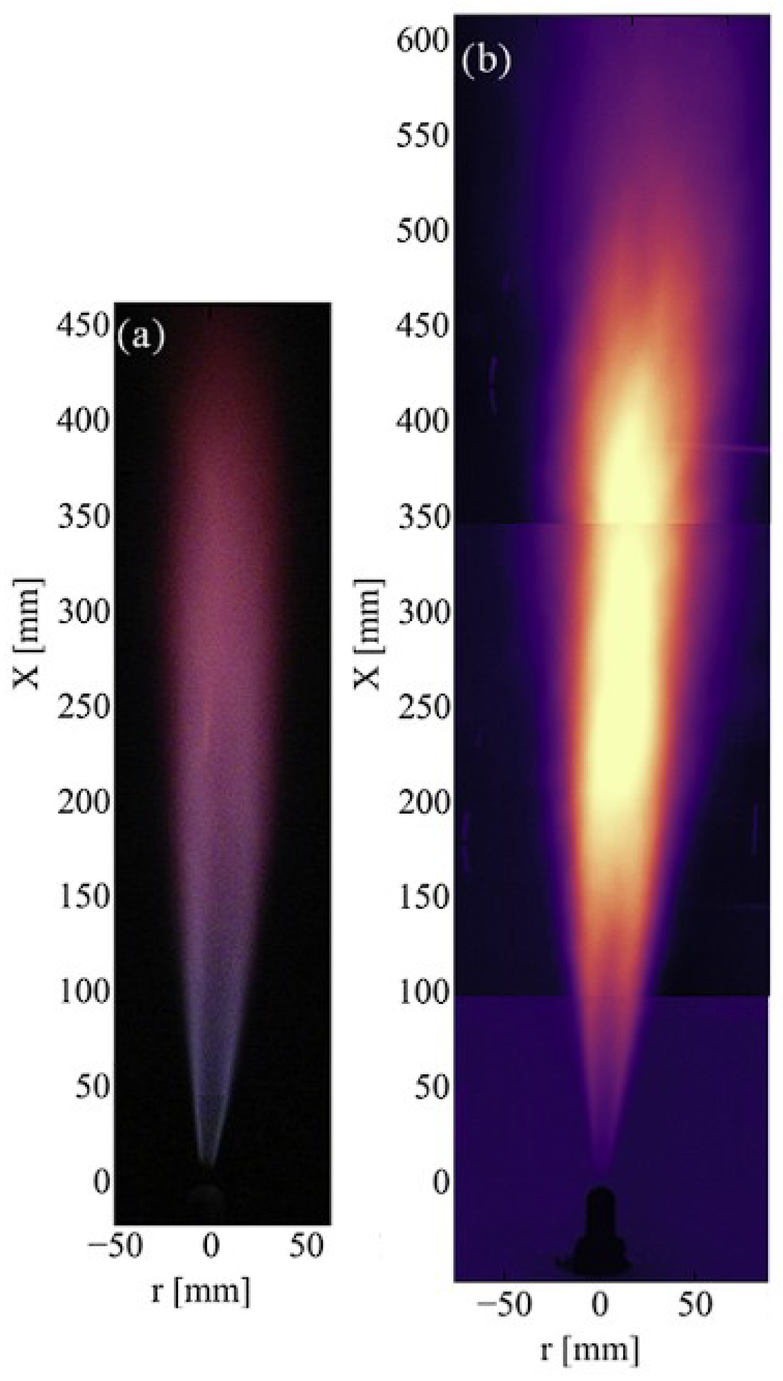
It was observed that the maximum ignition distance for a cold cryogenic hydrogen jet was larger than that of a room-temperature jet, for a fixed mass flow rate. A linear relationship was determined between the maximum ignition distance and nozzle exit diameter. The flame length was found to increase linearly with the square root of the Reynold’s number of the hydrogen jet. Finally, the radiative heat flux increased as the exit temperature was decreased. Another interesting insight presented in this paper was the comparison of the flame length for the same cryogenic hydrogen jet, using a time-averaged infrared (IR) image and visible image. The comparison can be seen in Figure 14 [53], which displays the resulting flame of the hydrogen jet from a nozzle diameter of 1 mm, with an exit pressure of 2 bar and temperature of 55 K.
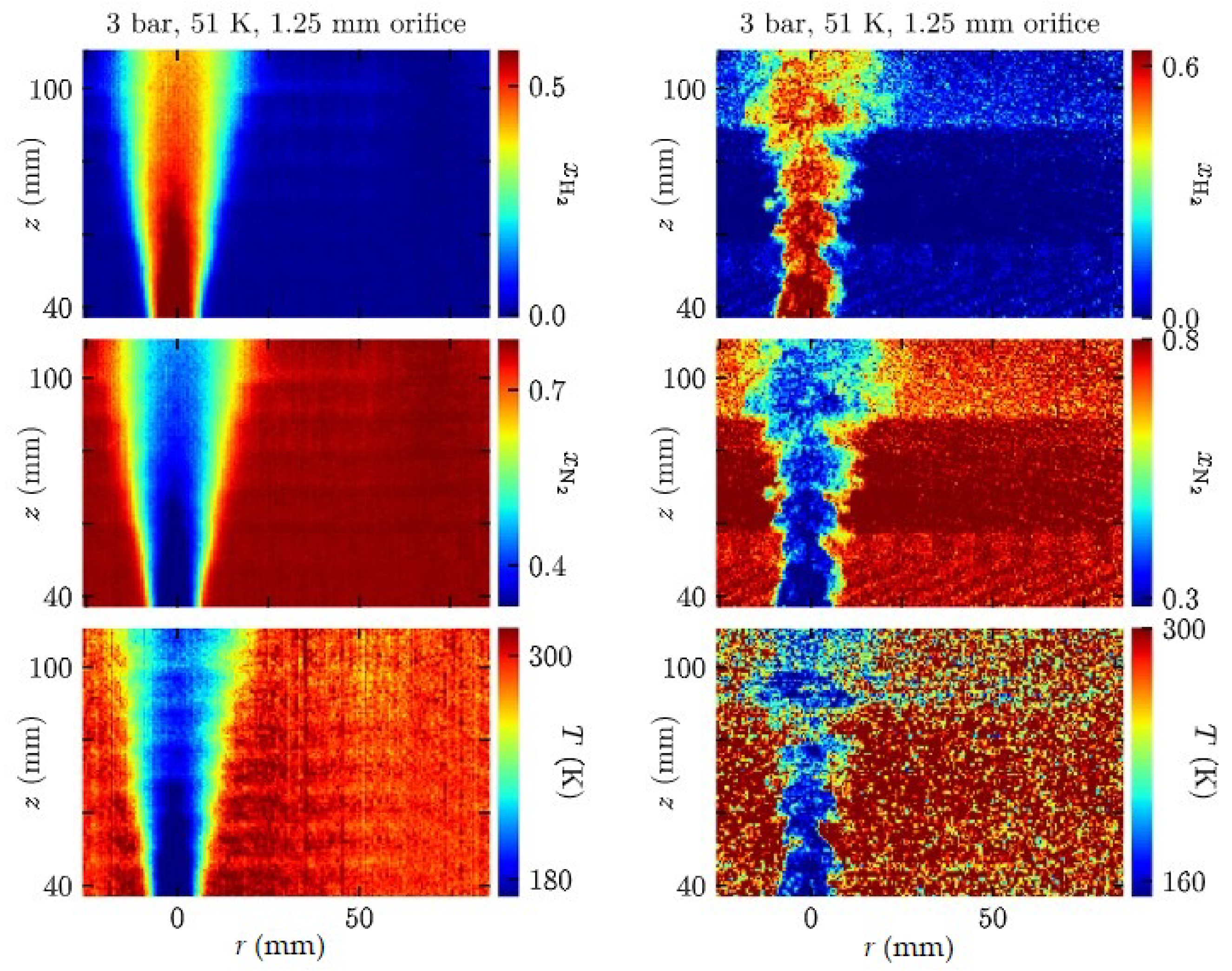
Another series of experiments undertaken at SNL was later released in 2019, by Hecht et al. [54,55,56], on unignited and ignited releases of cryogenic hydrogen. In [54], the results for ignited hydrogen jets were once again presented, as in [53], along with additional Raman imaging results for the characterisation of unignited cryogenic hydrogen jets. In this experiment, two cameras were used to obtain Raman-scattered light from hydrogen and nitrogen, as shown in Figure 15.
These data were then converted to yield the hydrogen and nitrogen mole fractions and temperatures for the unignited hydrogen jet, through the use of background normalisation, as described in detail in [55]. The resulting hydrogen mole fraction, nitrogen mole fraction and temperature distributions for the median values from the set of images are visualised in Figure 16 [54].
A similar investigation was undertaken using the Raman scattering imaging technique in [56], which looked at the dispersion of cryogenic hydrogen jets through high-aspect-ratio nozzles. The use of high-aspect-ratio nozzles provides similar characteristics to unintended leaks, which would occur through cracks, rather than the more conventional round nozzles.
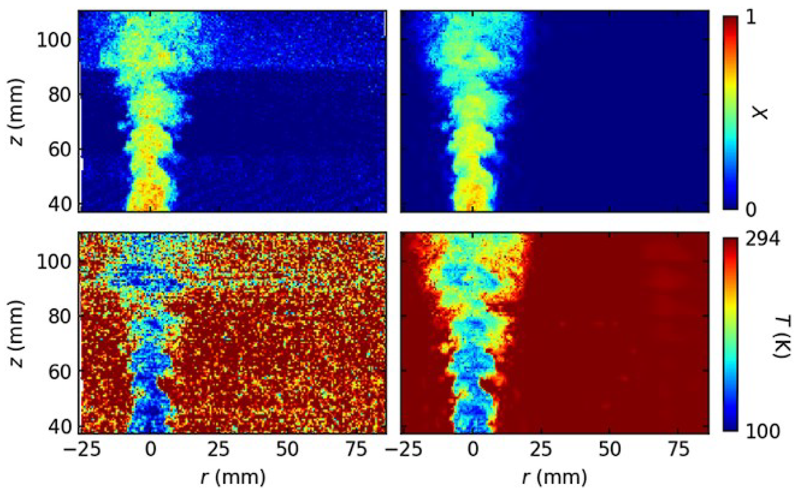
To improve the quality of the results from the Raman scattering signals in [55,56] and allow for an enhanced statistical study on the concentration fluctuation of cryogenic hydrogen jets, a ‘denoising’ algorithm was recently developed by Hecht et al. in [57]. A comparison of the instantaneous mole fractions and temperatures is displayed in Figure 17, for results with and without the application of the denoising algorithm.

3.2. Karlsruhe Institute for Technology (KIT)

The Karlsruhe Institute for Technology (KIT) is a national research center of the Helmholtz Association in Germany and a public research university of excellence. KIT was established in 2009 and was the amalgamation of the University of Karlsruhe and the Karlsruhe Research Center. It is known to produce the best engineering research in Germany.
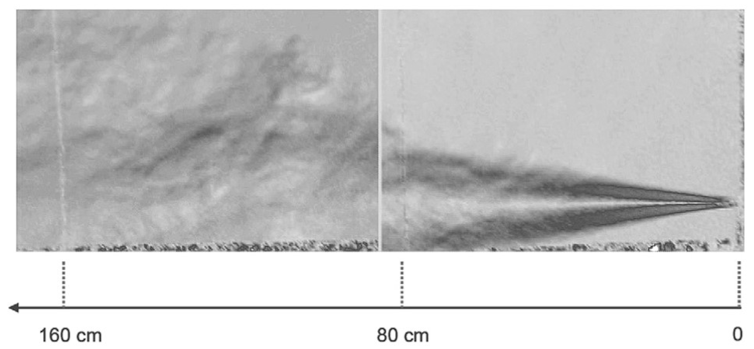
Some experiments were undertaken at KIT to study the flame characteristics of ignited hydrogen jets at both normal and cryogenic temperatures. Veser et al. published an experimental study on the structure and flame propagation of turbulent hydrogen jets in 2010 [58]. In this experiment, a hydrogen injection system was developed at the HYKA facility at the KIT Institute for Nuclear and Energy Technologies. The initial pressure of the released hydrogen was varied between 5 and 60 bar; different initial temperatures of 35 K, 80 K and 290–298 K were used, along with variations in the nozzle exit diameter. Two different sets of experiments were undertaken; the first was to measure the hydrogen concentration and flow distributions for the unignited jet. The second was the ignition experiment, in which an established steady-state hydrogen jet was ignited; this is known as ‘late’ ignition. To visualise the hydrogen jet flow and determine the two-dimensional velocity distribution, the test facility was equipped with Background-Oriented Schlieren (BOS) and Particle Image Velocimetry (PIV) systems, as described in [59,60], respectively. An image of an unignited hydrogen jet can be seen in Figure 18, as produced in [58] using the BOS system.
In addition to these visualisations, resulting radial hydrogen distributions, radial velocity profiles at different distances from the nozzle were presented, along with the measured axial velocity as a function of distance from the nozzle for the first set of unignited experiments. Then, an investigation on the flame propagation regimes for different ignition locations was undertaken in the second set of experiments. The ignition distance was varied between 50 and 275 cm from the nozzle exit. From the BOS image results for the different ignition locations, two different flame propagation regimes were identified. The first was referred to as a ‘fast’ combustion, in which the flame was able to propagate upstream to the point of ignition (flashback), resulting in a fully ignited hydrogen jet. In the second, named the ‘slow’ combustion regime, the flame was unable to propagate upstream and moved downstream only, before quenching. It was indicated from these results that a hydrogen jet was unable to become fully ignited (fast combustion regime) if the ignition location lay outside the iso-concentration line with 11% hydrogen. Example images for each of these regimes are visualised in [58].
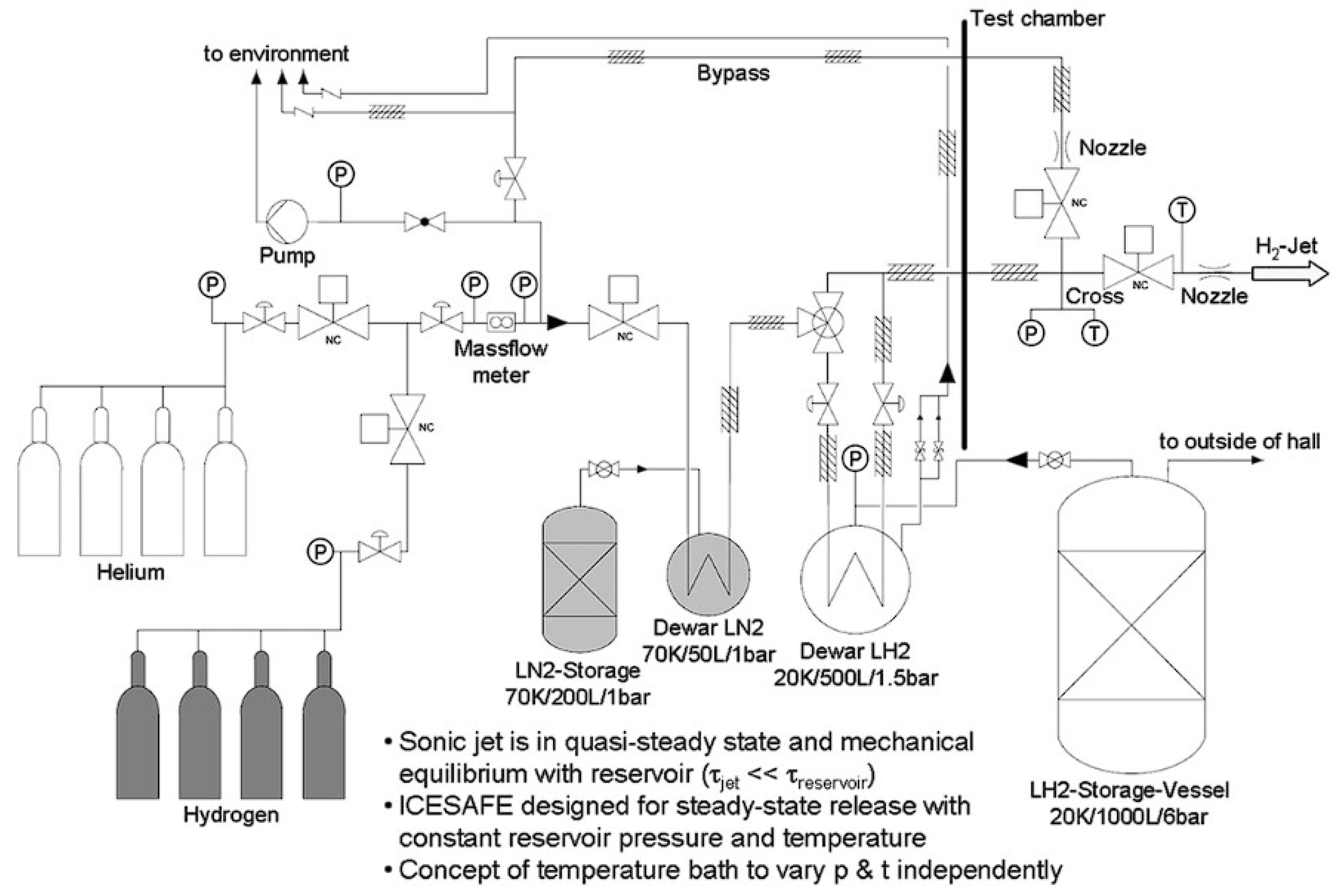
Later, in 2012, Friedrich et al. published an additional experimental paper on the ignition and heat radiation of cryogenic hydrogen jets [61]. In this work, undertaken at the Integrated Cable Energy Safety Analysis Facility and Equipment (ICESAFE) facility at KIT, cryogenic hydrogen jet dispersion and ignition experiments were studied at temperatures between 35 and 65 K and pressures between 0.7 and 3.5 MPa, along with different circular nozzle diameters. The flame stability and propagation characteristics were studied as a function of the ignition distance, as in the previous study by Veser et al. However, additional measurements of combustion pressures, heat radiation, safety distances and sound levels were also reported in this work. A total of 37 different experiments were carried out under various conditions, with the results of each provided in [61]. It was concluded that the hydrogen jets measured in this study showed no hazards to exposed persons, with respect to both the flame safety distances and maximum transient and stationary sound levels. An additional combustion regime was identified in this study that was not mentioned in [58]. This third combustion regime was the stable burning of the hydrogen flame close to the ignition point, without flashback or quenching phenomena occurring. Measured scaled distances and equations for flame flashback were developed to predict the absolute distance of flashblack for other leak diameters and reservoir densities. To aid in the prediction and calculation of this flame flashback distance, a plot was generated, as seen in Figure 19. A schematic diagram of the layout of the experimental setup used at the ICESAFE facility is presented in Figure 20, from [61].

3.3. New Energy and Industrial Technology Development Organization (NEDO)

More recently, the New Energy and Industrial Technology Development Organization (NEDO) in Japan carried out experiments on the release of unignited and ignited cryo-compressed hydrogen. NEDO is Japan’s largest public management organisation and promotes the research, development and deployment of energy, industrial and environmental technology. It was established in 1980 with the aim to respond to the climate and energy crisis by developing alternative energy sources to fossil fuels.
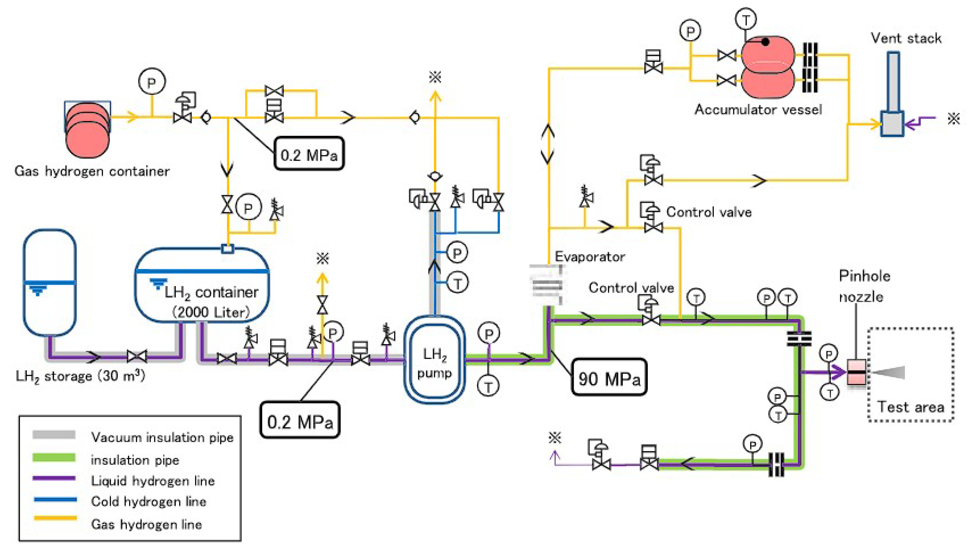
An experimental study on the leakage diffusion of unignited cryo-compressed hydrogen jets was undertaken by Kobayashi et al., as released in 2018 [62]. In these experiments, hydrogen was stored at the high pressure of 90 MPa, with the exit temperature being varied between 50 and 300 K, with a maximum mass flow rate of 100 kg/h through various nozzle diameters between 0.2 and 1 mm. The experimental setup is displayed in Figure 21 below, which was presented in [62].
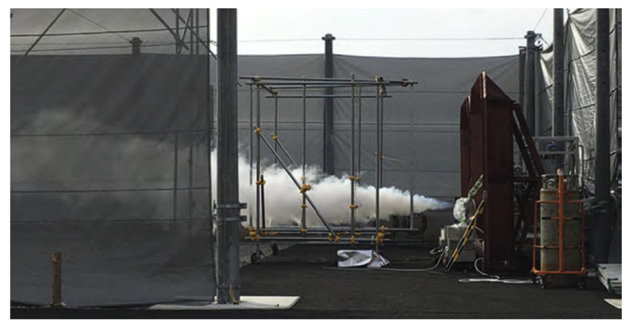
A high-pressure hydrogen jet generated through the pinhole injection nozzle and into the 50 × 16 m test area can be seen in Figure 22 [62]. In these tests, the leakage mass flow rate and hydrogen concentration distributions were measured. It was found that the measured mass flow rate and hydrogen concentration increased as the hydrogen supply temperature decreased. An empirical formula was also proposed in this study to predict the 1% concentration distance of 82 MPa for cryogenic hydrogen leaks through a 2 mm diameter pinhole nozzle.
An additional set of experiments was later published by Kobayashi et al. in 2020, on the flame resulting from the ignition of cryo-compressed hydrogen jets [63]. The same experimental setup was used as in Figure 21, except for the addition of an igniter, which was used once a steady hydrogen jet was established. The blast pressure at the location of ignition and the flame length were measured once the hydrogen jet was fully ignited. Blast piezo pressure sensors and visible light imaging with CCD cameras and image processing were used to achieve these measurements. To be able to observe a transparent, colourless flame, saltwater was sprayed through a sprinkler system onto the hydrogen jet. The observation of the ignition process of the cryogenic hydrogen jet from the CCD cameras can be seen in Figure 23. Additional images were presented in [63], highlighting the blast waves resulting due to the jet ignition. Other major findings of these ignition experiments were that the maximum overpressure was proportional to the leakage flow rate, the flame length increased with lowered temperatures and the hazard associated with the hydrogen flame worsened as the hydrogen temperature was lowered.

3.4. Health and Safety Executive (HSE) Science and Research Centre

The United Kingdom’s HSE Science and Research Centre, formerly known as the Health and Safety Laboratory (HSL), is located in Buxton and carries out research into new methods for safety in industry. Experimental studies were undertaken at HSE to enhance the understanding of the safety risks associated with the unignited and ignited release of liquid hydrogen.
In 2011, Hooker et al. undertook large-scale two-phase hydrogen jet experiments at the HSE laboratory, as published in [64]. In these sets of experiments, different release directions were studied at the constant volume flow rate of 60 L/min and nozzle exit diameter of 2.63 cm. Horizontal releases, only 3.4 mm aboveground and 86 cm aboveground, were completed, along with a downward vertical release from a height of 10 cm aboveground. The concentration of hydrogen in the air, the formation of liquid pools, the temperatures within these pools and the flame velocity, thermal radiation, sound pressure and flammability range were investigated in this study. Visible spectrum and IR recordings were also taken to visualise the jet and flame characteristics.
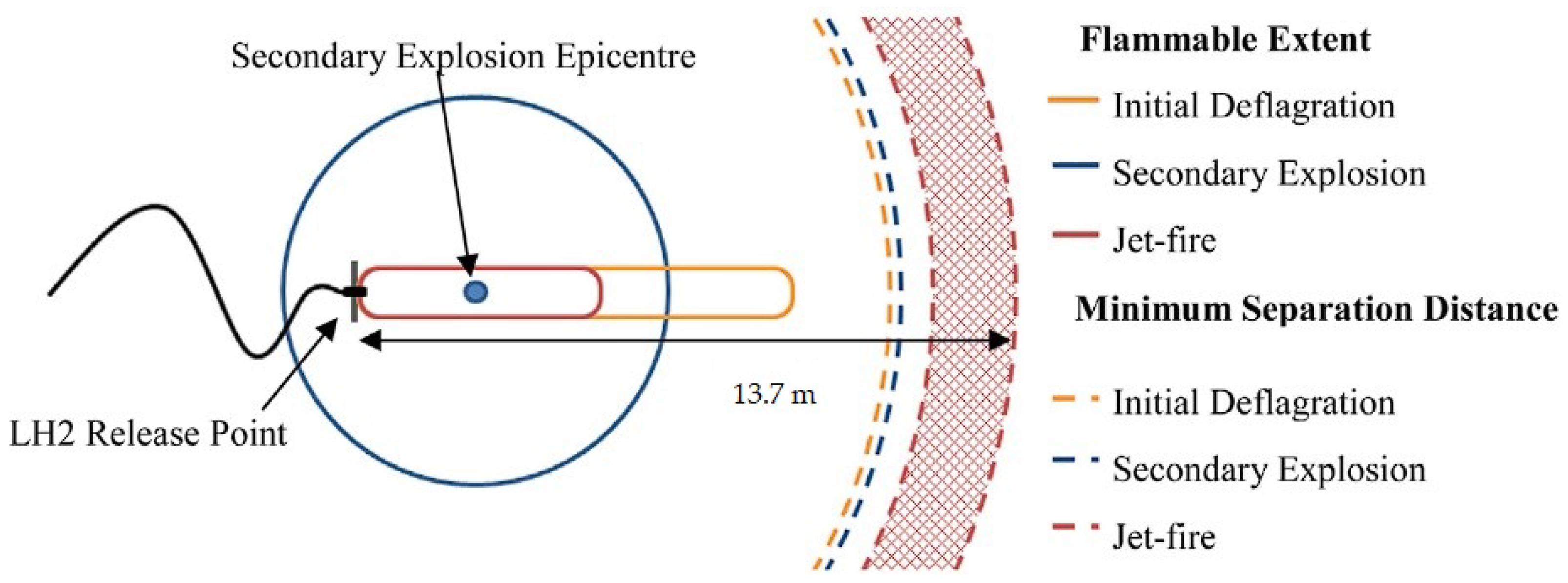
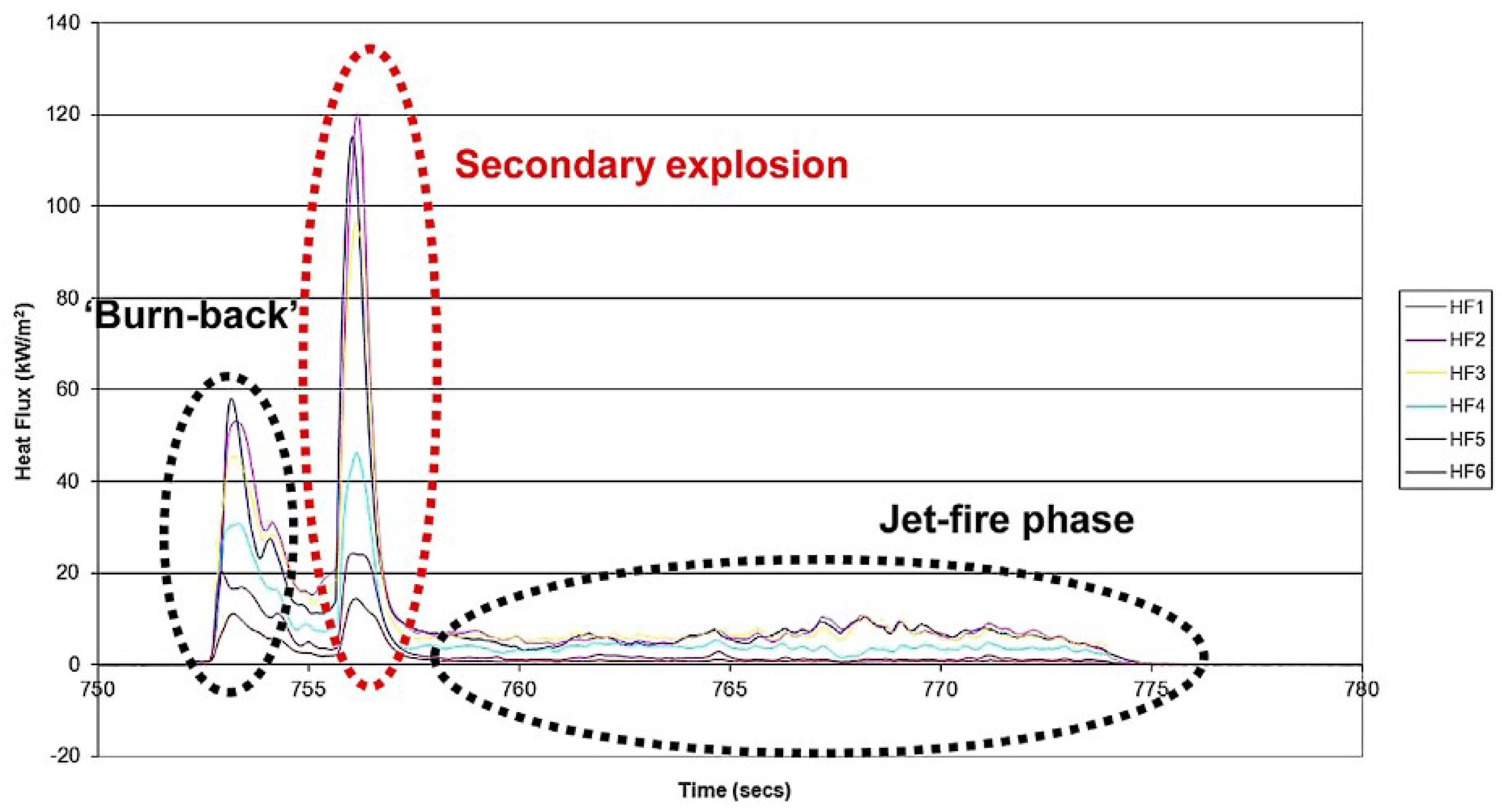
Later, another set of experimental results was released by Hooker et al. in [65]. These experiments focused more on the phenomena associated with ignited releases of liquid hydrogen, such as ‘burn-back’ and resulting secondary explosions. Along with measurements of flammability limits, flame speeds and radiative heat levels, as in [64], the magnitude of a secondary explosion was estimated. A secondary explosion occurs due to the solid deposit generated during the initial deflagration when the initial cloud becomes oxygen-enriched. It was estimated that these secondary explosions would have energy equivalent to roughly 4 kg of TNT.
A scale drawing of the flammability ranges and formation of a secondary explosion is depicted in Figure 24, as seen in [65]. Measurements of heat radiation from the radiometers during the ignited releases with secondary explosions are presented in Figure 25 below, from [65].
The data from both of these studies at HSE have been used to aid the development of safety standards and codes for the offloading of LH2 at storage and refuelling facilities.

3.5. National Aeronautics and Space Administration (NASA)

The National Aeronautics and Space Administration (NASA), an agency of the Unites States federal government, was established in 1958 and is responsible for the US Space Program. NASA is also responsible for a large volume of cutting-edge space and aeronautical-oriented research.
NASA was one of the first to experiment and study the hazards associated with the release of liquid hydrogen, with publications dating back to the 1960s [66]. This research was undertaken to develop safety criteria before the large-scale production of liquid hydrogen was realised. Later, in 1984, another series of large-scale liquid hydrogen spill dispersion experiments was completed at NASA’s White Sands Test Facility in New Mexico [67]. The basic phenomena resulting from the formation of flammable hydrogen clouds due to large-volume horizontal leaks of liquid hydrogen were investigated. Numerous experiments were carried out with hydrogen spill volumes of up to 5.7 m3 and a spill duration of roughly 35 s. Along with measurements of the temperature, hydrogen concentration and turbulence levels, motion and still cameras were used to visualise the flow phenomena.

3.6. Additional Experimental Studies

Numerous other experimental papers on cryogenic hydrogen jets and flames have also been presented by various researchers across the world. The evaporation speed of liquid hydrogen was observed by Nakamichi et al., using high-speed CCD cameras and a PIV system [68]. Unignited low-temperature hydrogen release tests were performed by Gong et al. with a storage pressure of 0.5 MPa, for various temperatures (200, 250, 300 K) and nozzle diameters (1, 1.5, 2 mm) [69]. The flame characteristics, including the flame length, width, thermal radiation fluxes and flame temperatures, of the downstream region of a cryogenic hydrogen jet fire were measured by Yu et al. in [70]. The supersonic structure of a hydrogen jet, the self-ignition and the associated explosion from a release opening of 15 mm were studied experimentally by Mironov et al. in [71]. Kitabayashi et al. performed experiments in which the high-pressure hydrogen was released through tubes of varying length between 0.1 and 4.2 m [72]. The shock wave and spontaneous ignition phenomena resulting from the release of hydrogen from a high-pressure tube were also studied experimentally by Duan et al. in [73], similar to the experiments undertaken by Kessler et al. [74].

4. Overview of Numerical Simulation Studies

Performing experiments is a necessity when studying new phenomena; however, the use of cryogenic hydrogen proves very expensive with respect to time and money. There are also many associated safety risks to human life. For these reasons, many numerical simulation studies on cryogenic hydrogen jets and flames have been carried out by researchers. To numerically simulate the release of unignited and ignited cryogenic hydrogen jets, computational fluid dynamics (CFD) is implemented, coupled with various sub-models and equations of state (EoS). CFD is the process of numerically solving complex theoretical mathematical models that govern fluid flow and physical phenomena, through the use of computational power. High-performance computing (HPC) and supercomputer clusters are often required to achieve more accurate approximate solutions to complex fluid flow problems. This section of the review paper focuses on the CFD and numerical studies that have been previously undertaken by researchers from different institutions across the world. Many of the results and codes produced in these studies have been validated through comparison to experimental measurements, as described in Section 3.

4.1. Equations of State

To obtain and model the thermo-physical properties of hydrogen, an equation of state (EoS) is utilised. The most commonly known EoS is the ideal gas equation [75], which provides a very simple relation between pressure, volume and temperature. However, due to the numerous assumptions and idealisations made in the ideal gas equation, it is not suitable for application to cryogenic hydrogen jets. There are numerous alternatives to the ideal gas equation, which are often referred to as ‘real’ gas EoSs. The following is an overview of the many alternative EoSs used in related research. A popular example is the stiffened gas (SG) EoS, which has been applied in numerous studies [76,77,78,79,80]. The SG EoS is a simple first-order equation that is often used when considering a fluid under very high pressures with small variations in density. Another well-known EoS is the Nobel-Abel (NA) EoS, as defined in [81,82]. This first-order EoS is known for being very simple yet reasonably accurate and can be used when the gas temperature is significantly high in comparison to the intermolecular attraction energy. For this reason, it is often found that the NA EoS is applied in ballistic, rocket propulsion and missile applications. Recently, in 2016, Saurel and Métayer combined the NA and SG EoSs and proposed the Noble–Able stiffened gas (NASG) EoS [83]. The NASG EoS was developed for application to hyperbolic two-phase compressible flow models and as an improvement to the previous SG EoS, through the inclusion of the repulsive effects. The NASG EoS has also proven popular in the field of cryogenic hydrogen, as demonstrated in later sections of this review paper. Saurel and Chiapolino later extended the NASG EoS for application to sub- and supercritical liquid–gas flows far from a critical point, in 2018 [84]. This was done by including variable attractive and repulsive effects, which enhanced the accuracy of liquid phases when considering large pressure and temperature variation ranges. There are numerous other EoSs that vary in complexity and suitability for certain applications. Some of these include the Redlich–Kwong (RK) [85], Redlich–Kwong–Soave (RKS) [86], Peng–Robinson (PR) [87], Patel–Teja (PT) [88], Beattie–Bridgeman (BB) [89] and Mie–Gruneisen (MG) [90,91] equations of atate. Many of these are commonly used in computational fluid dynamics (CFD). However, what is considered to be the current standard EoS for hydrogen can be found in [92], which is often referred to as the ‘NIST EoS’, as used by the National Institute of Standards and Technology (NIST) online database and software package (REFPROP). This EoS is complex but highly accurate, as it takes into account the quantum physics that come into effect with hydrogen at very low cryogenic temperatures. The equation uses explicit Helmholtz free energy and has been validated for a temperature range from 14 to 1000 K and pressures up to 2000 MPa.

4.2. Multiphase Flow Models

During the release of cryogenic hydrogen, multiple physical states may be present in the flow, including liquid, gas and potentially even solid. This is due to the significant temperature gradient between the cryogenic hydrogen and atmospheric air. As a result of this, multiphase reactive flow models are required to more accurately predict the characteristics of hydrogen jet releases. Multiphase reactive flow refers to the modelling of chemical reactions within the fluid phase and at the interphases between different fluids or solids. These types of fluid flows are very difficult to model entirely accurately, and the correct mass transfer model must be selected for each type of situation. There are many different approaches that can be taken to model multiphase, reactive flow, but a few are discussed in the following. In 2008, a multiphase model was proposed by Saurel, Petitpas and Abgrall, capable of modelling phase transitions in cavitating and flashing flows [93]. In fluid mechanics, cavitation is a phenomenon that occurs when the local static pressure quickly drops below the vapour pressure, causing small gas cavities to be created within the liquid. Flashing refers to the state transition from liquid to gas, due to a sudden drop in pressure. It is similar to evaporation, which is caused due to an increase in temperature. This two-phase compressible flow model involves a set of five partial differential equations (PDE), allowing for the tracking of liquid–gas interfaces and phase transitions in metastable fluids. These five PDEs must be closed using two thermodynamic equations of state (EoSs), which are further discussed in the following section. The model was validated through a comparison of the numerical results to previous experimental data for a number of test problems. A seven-equation set of PDEs was later applied to this same set of metastable liquid test problems and compared to the original results of Saurel et al. by Zein, in his 2010 doctoral thesis [94]. It was observed that Zein’s results were similar to Saurel’s, with only a few differences, but with greater computational costs associated with the use of the seven-equation model. Another relevant multiphase model was later proposed by Boivin, Chiapolino and Saurel in 2016, which aimed at creating a faster phase transition solver for liquid–vapour flows [76]. This paper focused on the four-equation homogeneous relaxation model (HRM) [95] as the starting point. A series of papers and developments on this model were published over the following years, as seen in [96,97,98]. In [98], Boivin applied the latest model to sub-critical cryogenic jet flows, including an investigation involving hydrogen.

4.3. Unignited Hydrogen Jet

Direct numerical simulations (DNS) were undertaken by Ren and Wen with a focus on characterising the near-field multicomponent compressible flow physics of underexpanded cryogenic hydrogen gas jets [99].
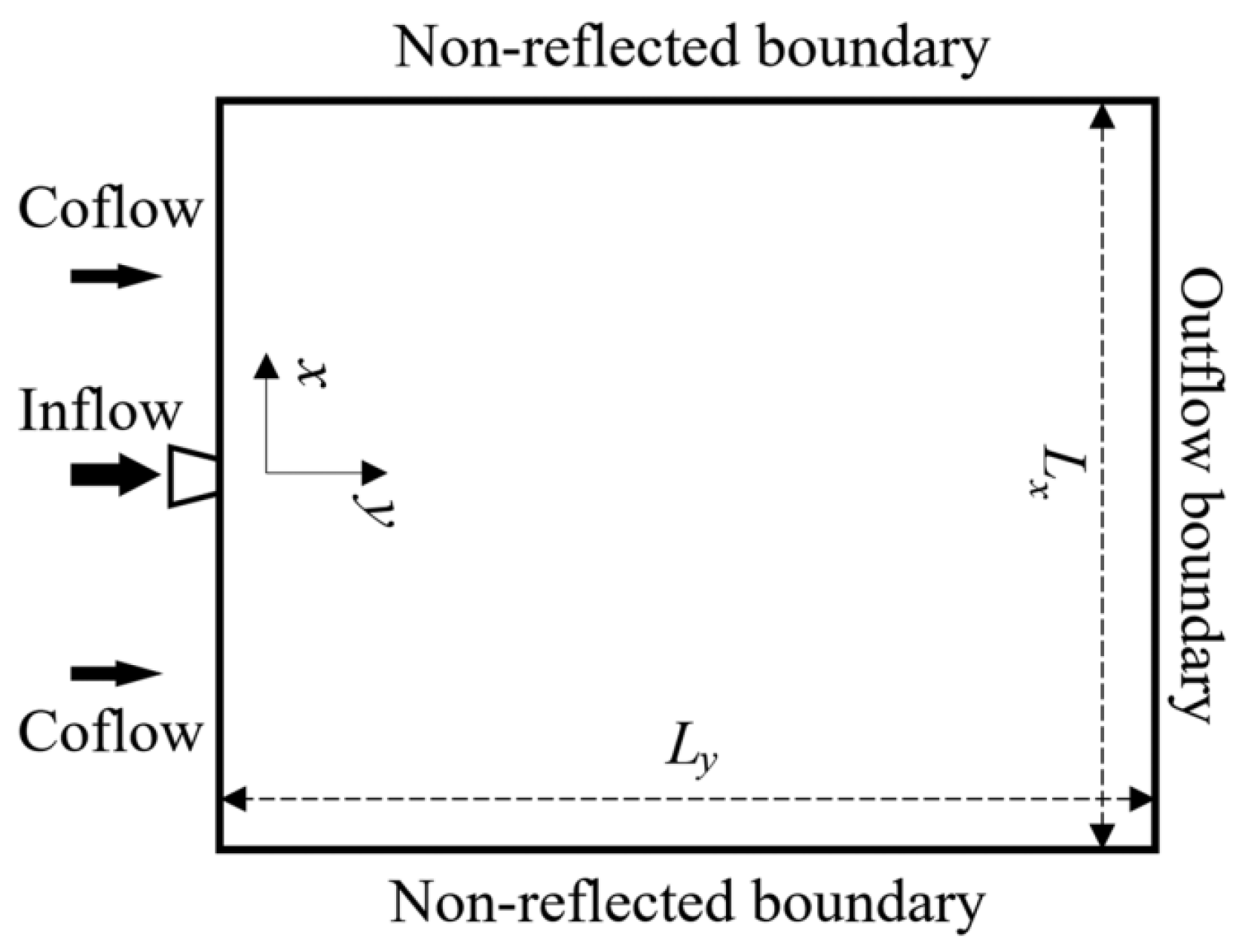
The boundary conditions and domain setup for the simulations can be seen in Figure 26 [99]. The effect of varying the nozzle pressure ratio (NPR) for values of 3, 4 and 5 was investigated, along with variations in the nozzle exit diameter between values of 0.75 and 1.5 mm at the constant NPR of 5. The governing equations directly solved in this analysis were the two-dimensional multiphase multicomponent compressible Navier–Stokes equations, coupled with the ideal gas equation and assuming Fourier heat conduction and Fickian mass diffusion, as detailed in the paper. The simulations were validated and based on the experiments carried out by Hecht and Panda at SNL, as detailed in Section 3.1 of this review. Through visualisation of the results, it was seen that the near-field formation of the underexpanded jet could be divided into four distinct regions. These were named the initial penetration (t = 0–10 μs),the near-nozzle expansion (t = 10–20 μs), the downstream compression (t = 20–30 μs) and the wave propagation stages (t = 30–40 μs). The evolution of the underexpanded hydrogen jet through each of these stages is visualised in Figure 27, Figure 28 and Figure 29 [99], for the case with NPR equal to 5 and a 1 mm nozzle diameter.
These figures display the transient development of the flow in time steps of 10 μs, starting at time equal to 10 μs in the far left. Figure 27 shows the density distribution, the hydrogen mass fraction is shown in Figure 28 and the dimensionless pressure is shown in Figure 29. Through analysis of the results for the varied pressure ratios and nozzle diameters, it was observed that an increased pressure ratio was correlated with accelerated hydrogen dispersion and the increased size of the liquefaction potential regions. It was also found that increasing the nozzle diameter also increased the liquefaction potential regions, but resulted in the slower evolution of the flow structure. The penetration of the jet was roughly linear with respect to time and the shape of the jet head varied for each of the nozzle pressure ratios.
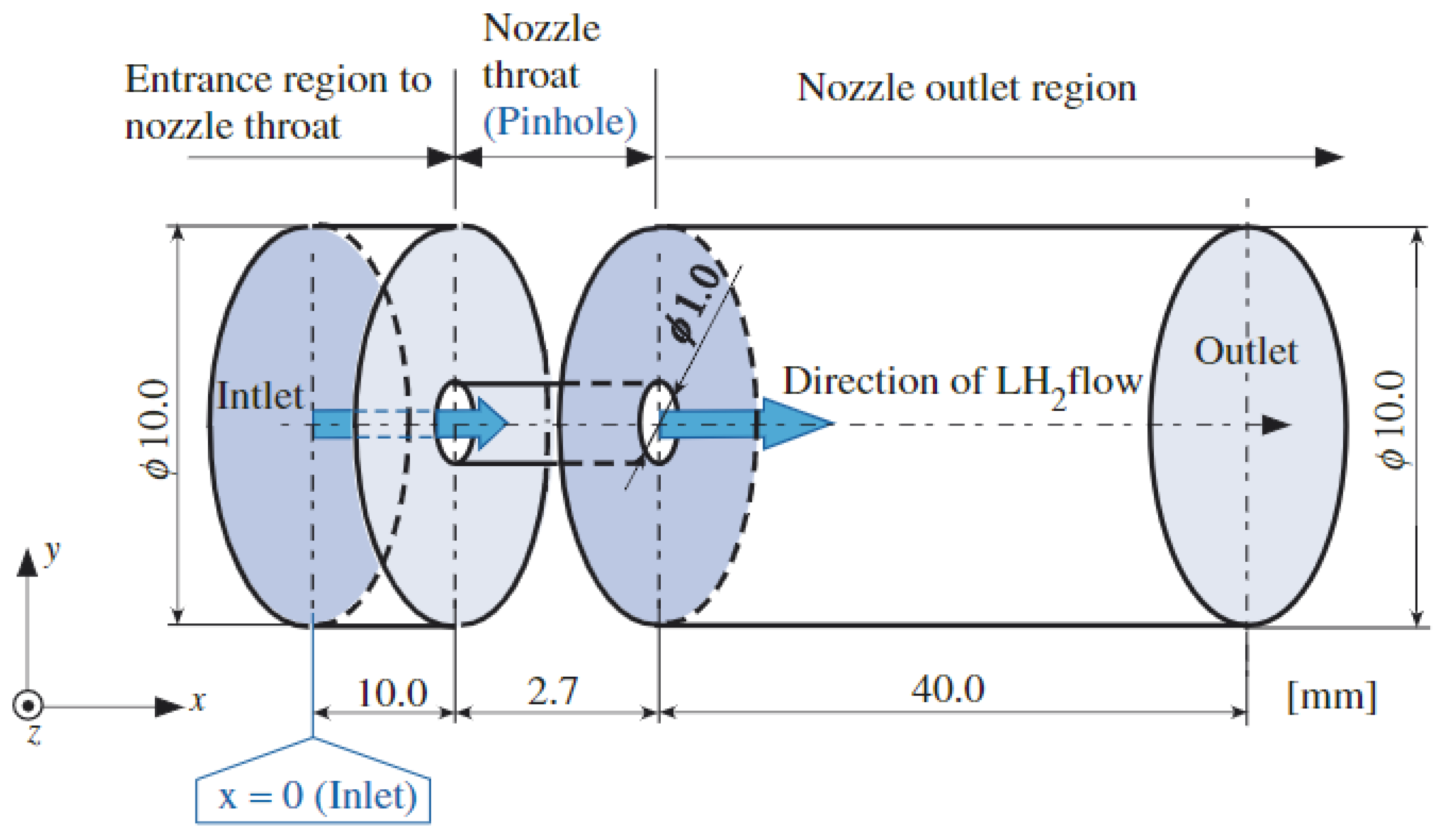
Ishimoto et al. investigated the atomisation process involved during the formation of a liquid hydrogen jet in 2008 [100], which was supported by NEDO. A drawing of the computational domain used in the study can be seen in Figure 30 [100].
The thermodynamic behaviour and associated phenomena with the release of liquid hydrogen through a pinhole nozzle were investigated in this paper. The CFD model was used to visualise the atomisation of the liquid hydrogen jet. The liquid-phase volume fraction distribution was plotted for this visualisation, along with a comparison to experimental images obtained by NEDO in [101]. This comparison is displayed in Figure 31 [100].
To achieve this, the proposed multiphase CFD model implemented incompressible turbulent Navier–Stokes equations, along with the large-eddy simulation–volume of fluid (LES-VOF) and continuum surface force (CSF) models. The VOF method is commonly used for the tracking of interfaces between two immiscible fluids, as it has the advantage of having no topological constraints. This CFD model was also employed to obtain data such as droplet velocity profiles, surrounding thermal fields, spray angles, liquid core shapes, atomisation lengths and droplet size distributions.
An additional CFD model named FLACS was further developed by Ichard et al. in 2012, extending the code capability to simulate two-phase liquid hydrogen releases [102]. This CFD code was compared and based on the experiments using liquid hydrogen undertaken at the HSE laboratories in the UK. The code was used to simulate two of the experiments performed at the HSE laboratory, one horizontal release and one vertically downward release of liquid hydrogen, as detailed in Section 3.4 of this review paper. FLACS achieves this by solving the three-dimensional Reynolds-averaged Navier–Stokes (RANS) governing equations, coupled with the k- ϵ turbulence model, the ideal gas equation of state and the homogeneous equilibrium model (HEM) for two-phase flows. Further information on these sub-models and their implementation into FLACS can be found in [102]. This study looked at the condensation and solidification of nitrogen and oxygen in air, with the continuous phases assumed to be in thermodynamic and hydrodynamic equilibrium. In the horizontal release test, it was found that this condensation and solidification of the air close to the ground resulted in a more buoyant jet. However, this buoyancy effect did not influence the flow in the vertical release test.
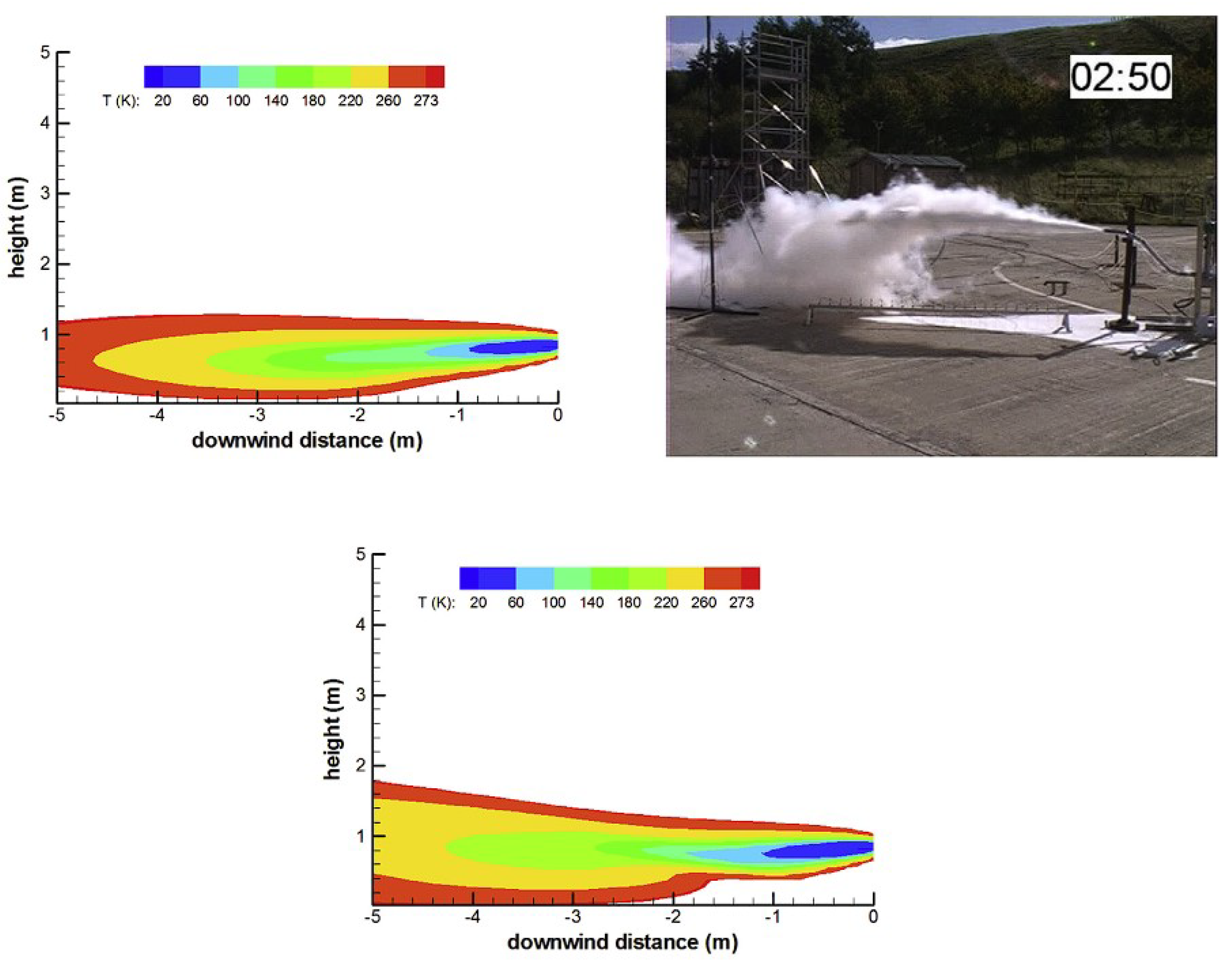
Later, in 2014, Giannissi et al. also carried out work to simulate the HSE liquid hydrogen experiments [103]. However, they used a different CFD code, called ADREA-HF, in their analysis. Unlike the previous work by Ichard et al., the effect of using a non-hydrodynamic equilibrium model was studied, through the use of a modified slip velocity model. This allowed different velocities to occur in the hydrogen vapour and non-vapour phases. The ADREA-HF code solves the Navier–Stokes governing equations, implementing the previously mentioned HEM model. ADREA-HF has different integrated turbulence models, such as the RANS equations, the k- ϵ model and the large-eddy simulation (LES) model. The k- ϵ model was the turbulence model selected in this work, coupled with additional buoyancy source terms.
A qualitative comparison of the numerical and experimental hydrogen cloud dispersion was performed, using Figure 32 [103], in which the CFD temperature distributions are presented. Overall, this study found that there was improved similarity between the simulation and experimental results when implementing the additional velocity slip model, when compared to [102].
The ADREA-HF code was used again to simulate cryogenic hydrogen jets by Giannissi et al. in a publication presented in the following year [104]. However, in this study, two of the unignited cryogenic hydrogen jet experiments performed at the KIT HYKA test site were simulated. In the first test, a mass flow rate of 0.00455 kg/s was used, with a reservoir pressure and temperature of 19 bars and 37 K. A mass flow rate of 0.00802 kg/s, pressure of 29 bars and temperature of 36 K were used in the second test. Both of these experiments used a 1 mm diameter release nozzle. Both the Ewan and Moodie approach and a modified Ewan and Moodie approach were used and compared to model the underexpanded jet and find the velocity at the notional nozzle. The notional nozzle approach was implemented to enhance the computational efficiency by bypassing the complex flow structures at the near-field flow region to the real nozzle. The Peng–Robinson EoS was used in this numerical analysis due to the high reservoir pressure and low temperature, providing similar reservoir hydrogen properties to the NIST real gas equation. The CFD predictions were similar to the experimental measurements, with a good correlation. The CFD results obtained using the Ewan and Moodie approach conditions allowed for slightly more accurate performance. A very similar analysis was later released by Giannissi and Venetsanos in 2016, in which the ADREA-HF code was further validated through simulations of additional KIT and NASA experiments [105]. The ADREA-HF code was again implemented by Giannissi and Venetsanos in an additional study that compared the performance of the non-homogeneous equilibrium model (NHEM) to the previously used HEM model [106], through comparison to HSE experiments. A comparison of the dispersion of liquid hydrogen, cryo-compressed hydrogen, liquid natural gas dispersion and liquid methane in an open environment was also carried out by Giannissi and Venetsanos, again using the ADREA-HF CFD code, in [107]. It was emphasised in this study that when evaluating the release of liquid hydrogen, the effect of humidity is significant and must be taken into account during simulations. This is due to the condensation and freezing of the air components, which leads to a more buoyant flammable vapour cloud, resulting in a reduced lower flammability limit. Recently, in 2021, Giannissi, Venetsanos and Hecht again employed the ADREA-HF CFD code and notional nozzle to simulate the previously described vertical release experiments performed at SNL [108]. There was good agreement found between the numerical and experimental results in this study, besides a slight deviation in spreading in the horizontal direction.
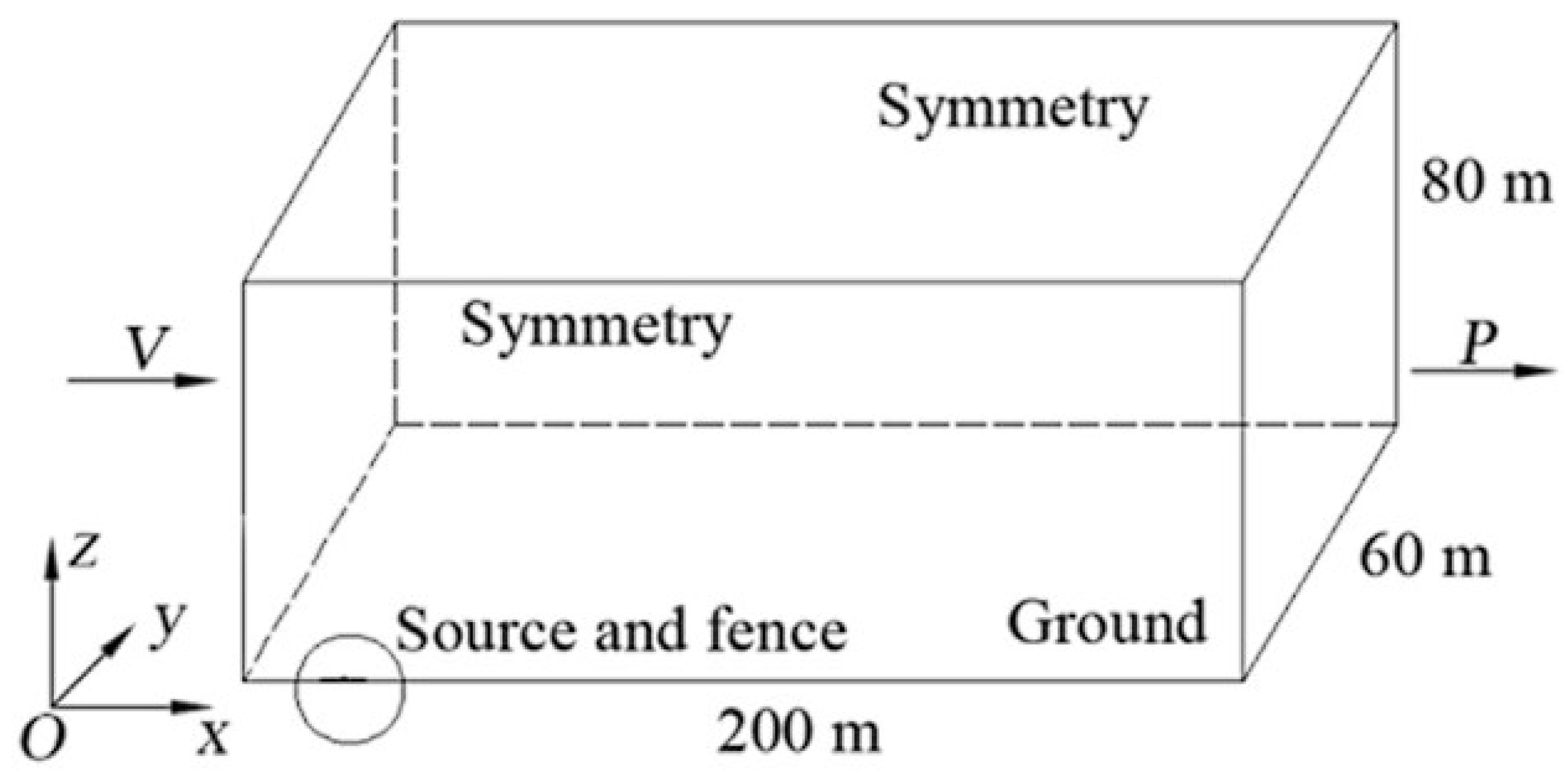
Jin et al. applied the commercial CFD software ANSYS Fluent (version 14.5) to study the flammable vapour cloud formed during the spillage of liquid hydrogen [109]. A depiction of the physical model geometry and domain can be seen below in Figure 33 [109].
In this numerical analysis, a three-dimensional model was employed, using a two-phase mixture model that assumed thermal equilibrium between states but different velocities, the k- ϵ turbulence model and the gas transport equation. The CFD results were validated through a comparison to experiments carried out by NASA, as previously detailed. The source/nozzle exit temperature, density, mass flow rate and pressure were set to 20.35 K, 70.8 kg/m3, 9.52 kg/s and 690 kPa.
A hydrogen concentration of 4% in the gas mixture was considered as the limit of flammability. The hydrogen concentration was plotted for the CFD results on the x–z plane and compared against experimental measurements from NASA, which can be seen in Figure 34 [109]. A similar formation pattern is evident in each of these sets of results. Additional plots of temperature contours, the hydrogen concentration against temperature and turbulent kinetic energy were presented in the paper.
A new CFD multicomponent–multiphase model was proposed by Jäkel et al., with the capability of simulating both liquid and gaseous hydrogen accidental release [110]. A NASA experiment and four HSE experiments were used for validation in this paper, with a mixture of horizontal and vertical release conditions. This CFD code uses the governing conservation equations for multiphase flows as defined by Brennan [111], along with a HEM vaporisation model with the real gas properties taken from NIST. Through comparison to these experimental results, it was seen that the CFD results showed a good qualitative correlation, with some quantitative deviations. The authors stated that this was due to experimental uncertainties. Nevertheless, this model requires further validation through comparison to additional experiments in the future.
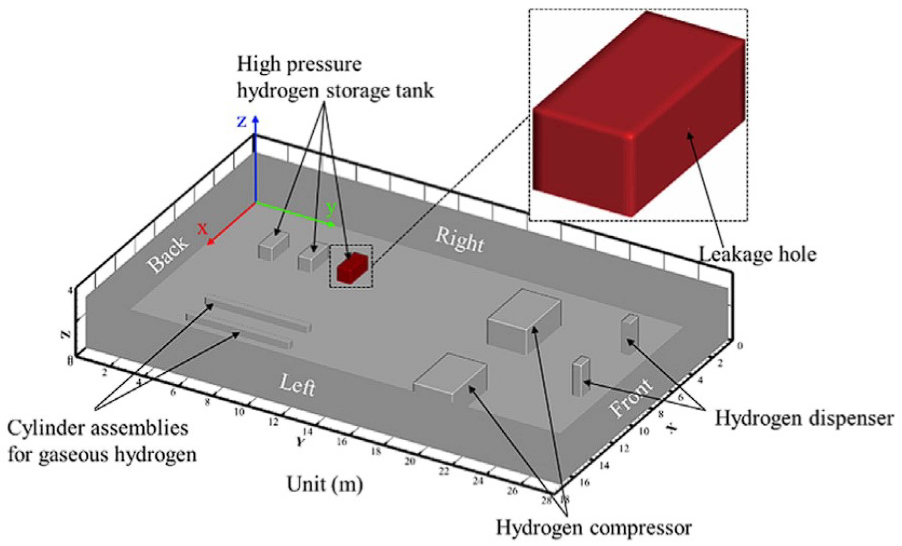
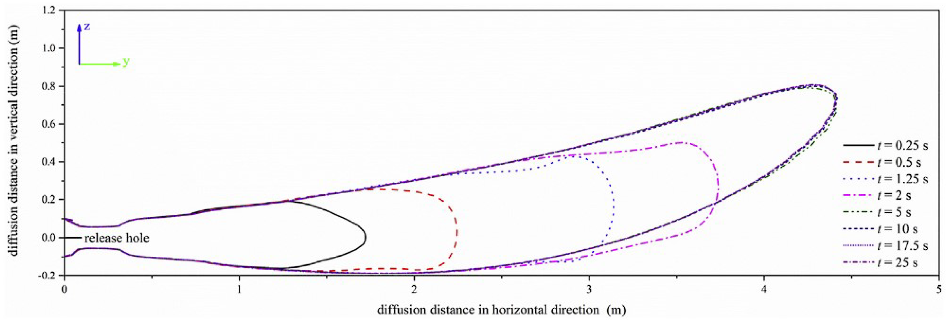
A numerical study on the dispersion of gaseous hydrogen during accidental releases at a hydrogen refuelling station was investigated using ANSYS Fluent by Qian, Li and Jin in 2020 [112]. The realisable k- ϵ turbulence model, species transport equation and Noble–Able EoS were implemented to simulate the resulting high-pressure underexpanded jet dispersion. Both momentum–buoyancy- and momentum-dominated jets were studied, with a comparison of the two sets of results. The release nozzle exit diameter was set to 10 mm, with various exit pressures and velocities studied. The densimetric Froude number (Fr) was employed to characterise whether the resulting release was momentum–buoyancy- (10 < Fr < 1000) or momentum-dominated (Fr > 1000), as proposed by Schefer et al. [113]. The domain and layout of the simulated release area are depicted in Figure 35 below [112]. The ambient temperature was set to 298 K, with atmospheric pressure assumed near to the leakage hole. The CFD results were validated against experiments undertaken by Swain and Grilliot in 1998 [114], using the same setup and boundary conditions, and displayed similar trends in the results, with a maximum error of 33%, which seems relatively large. For the momentum–buoyancy-dominated jet, the hydrogen gas cloud profile at various times is presented in Figure 36. The equivalent diagram for the momentum-dominated jet can be seen in Figure 37, with both presented in [113]. It was observed that it was more likely for the hydrogen gas cloud to form closer to the ground for momentum-dominated jets.
The FLACS CFD software was again applied by Hansen to numerically study liquid hydrogen releases, with a focus on safety considerations in the maritime industry [115]. A development version of the FLACS HEM model was applied to simulate one of the HSE experiments. This was the same HSE experiment as modelled by Giannissi et al. in 2014, using the ADREA-HF code as in [103]. The predicted hydrogen gas volume fraction of the resulting release jet can be seen in Figure 38, which shows a similar pattern to the results in Figure 32 obtained by Giannissi et al.
Additional simulations were undertaken for various maritime applications, including vent mast releases, with a comparison of results for both LH2 and LNG spills. From this, it was concluded that the design of LH2 storage vessels may require a higher standard of safety compared to the current LNG vessels.

4.4. Ignited Hydrogen Jet and Flame

Ren et al. recently released a numerical study on the evolution and structure of high-pressure ignited cryogenic hydrogen jets in [116]. The transient development and fine details of the flame structures resulting from cryogenic releases were simulated, based on experiments undertaken in PRESHLY [117]. A compressible reacting flow solver called rhoReactingFOAM, as described in [118], from the OpenFOAM open-source CFD framework, was implemented to carry out the numerical simulations. Within this solver, the Favre-filtered governing conservation equations are used, along with the one-eddy turbulence equation model by Yoshizawa [119], the modified EDC for combustion by Parente et al. [120] and additional detailed chemistry models. The release conditions used in the simulations were an exit nozzle diameter of 4 mm, pressure of 200 bar and a temperature of 80 K. The computational domain is presented in Figure 39.
Four different ignition locations were tested, resulting in different flame propagation attributes, as detailed by the authors. For the ignition location at a distance of 0.5 m from the nozzle exit, the development of the resultant flame over time is depicted in Figure 40, using iso-surface temperature plots. The corresponding OH radical distribution on the y–z middle plane was used to characterise the spatial distribution of the flame front, as presented in Figure 41. A flame kernel (FK) can be seen to form at the ignition location in (a), with flame extinguishment (FE) occurring in (f). Similar figures were presented in this paper for three different ignition locations, along with observations of delayed ignition deflagration waves, which implied the potential for explosions.
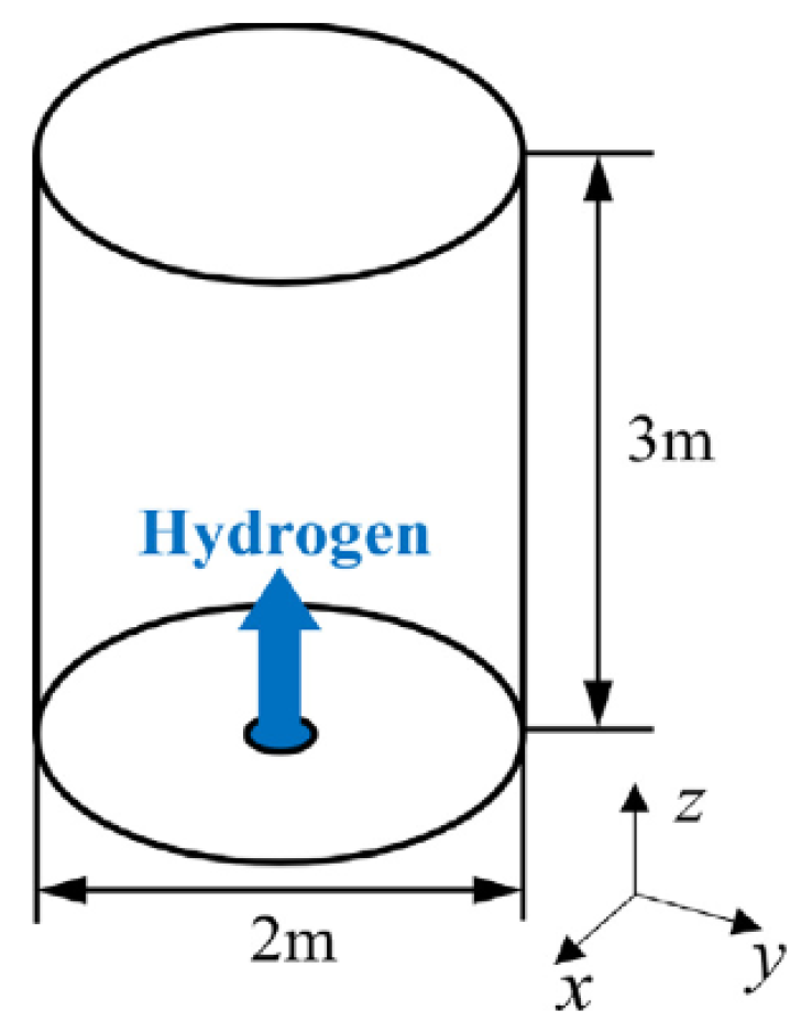
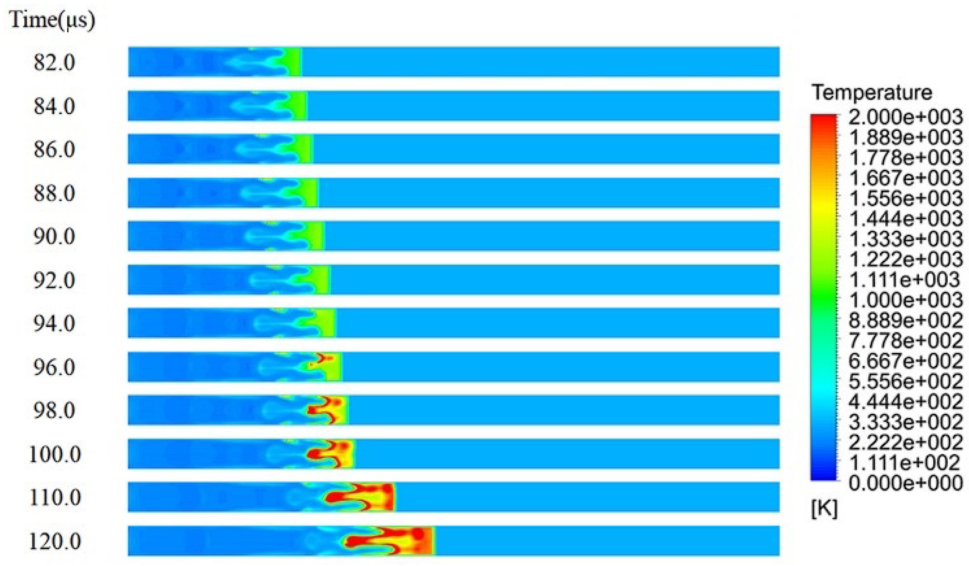
The spontaneous ignition of hydrogen during high-pressure release in a tube was numerically modelled by Gong et al. in 2020 [121]. The resulting spontaneous ignition mechanisms and resulting shock wave phenomena were characterised in great detail, based on CFD results. Spontaneous ignition is a phenomenon that occurs when the air–hydrogen mixture exceeds the critical spontaneous ignition temperature. This can occur when an underexpanded hydrogen jet is formed as a result of the heating of the air ahead of the leading shock wave, by the shock wave. Three different burst pressures were investigated and the results were validated against experimental measurements. ANSYS Fluent, along with the LES model, EDC combustion model and the Renormalisation Group (RNG) turbulence model, formed the basis of the CFD method in this work.
The computational domain employed by the authors can be seen in Figure 42 [121]. The resulting CFD transient progression of the temperature distribution for the case of a blast pressure of 8.45 MPa is depicted in Figure 43 and Figure 44 [121]. Figure 43 displays the initial stage of the hydrogen release into the tube and the location of the shock-affected region, with the later stages being presented in Figure 44.
From these results, five mechanisms for spontaneous ignition were identified, as visualised below in Figure 45. There is initial generation of a hemispheric shock as the air and hydrogen begin to mix. Then, normal and barrel shocks form, along with a mach disk, before spontaneous ignition at the tube wall. Finally, spontaneous ignition occurs inside the tube and the two combustion regions merge. An additional study on the spontaneous ignition of cryo-compressed hydrogen in a T-shaped channel was carried out by Cirrone, Makarov and Molkov [122].
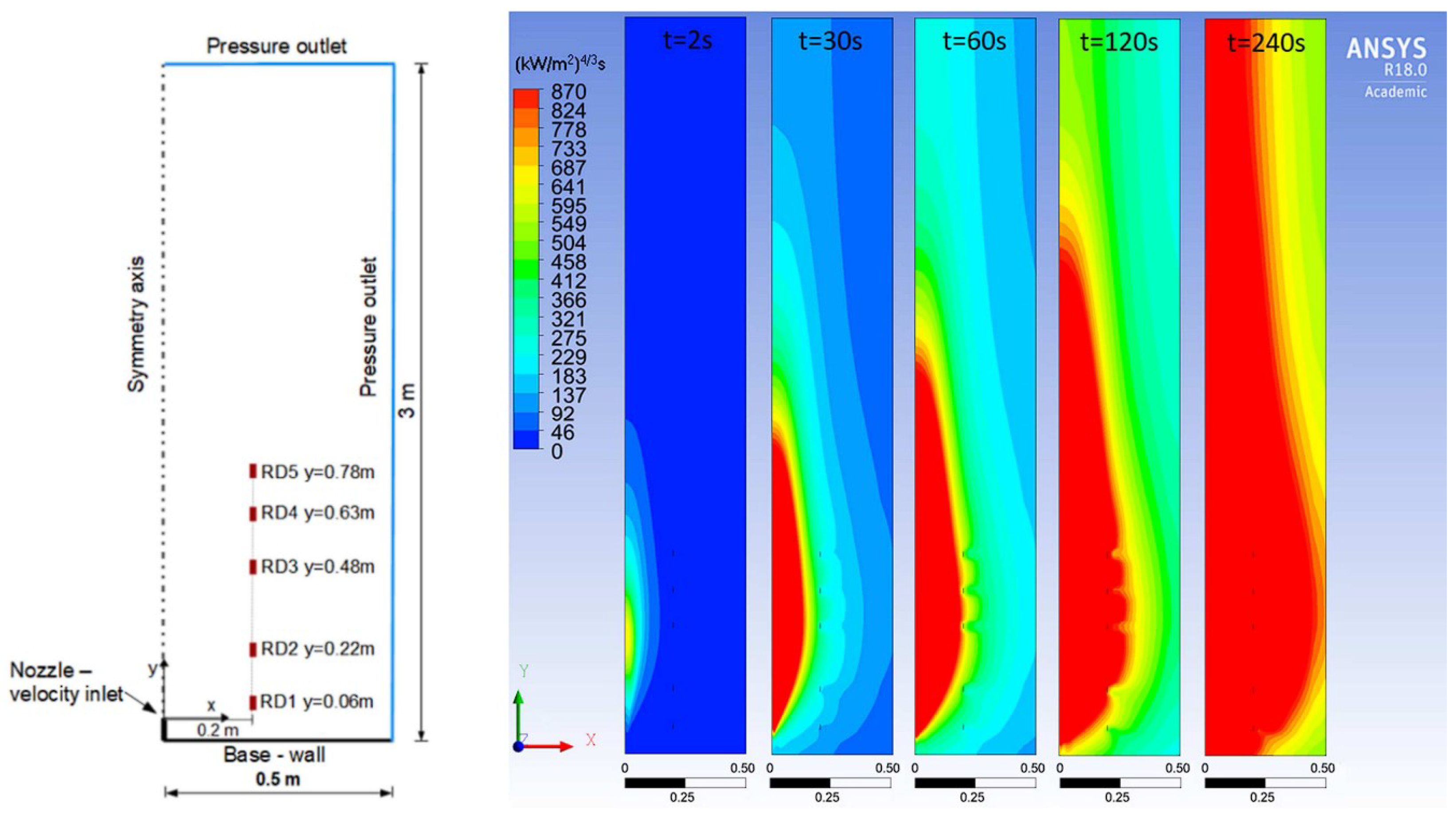
Cirrone, Makarov and Molkov released a numerical CFD study on the near-field thermal dose resulting from cryogenic hydrogen jet fires in 2019, based on three experiments performed at SNL [123]. Vertical releases from cryo-compressed vessels at pressures of up to 4 bar and various temperatures between 48 and 78 K were simulated, through an orifice that was 1.25 mm in diameter. The CFD method employed the RANS governing equations, the transport equations for turbulent kinetic energy coupled with the realisable k- ϵ turbulence model, the eddy dissipation concept for hydrogen combustion and the discrete ordinates model. The ANSYS Fluent software was utilised to solve this model, along with the notional nozzle theory.
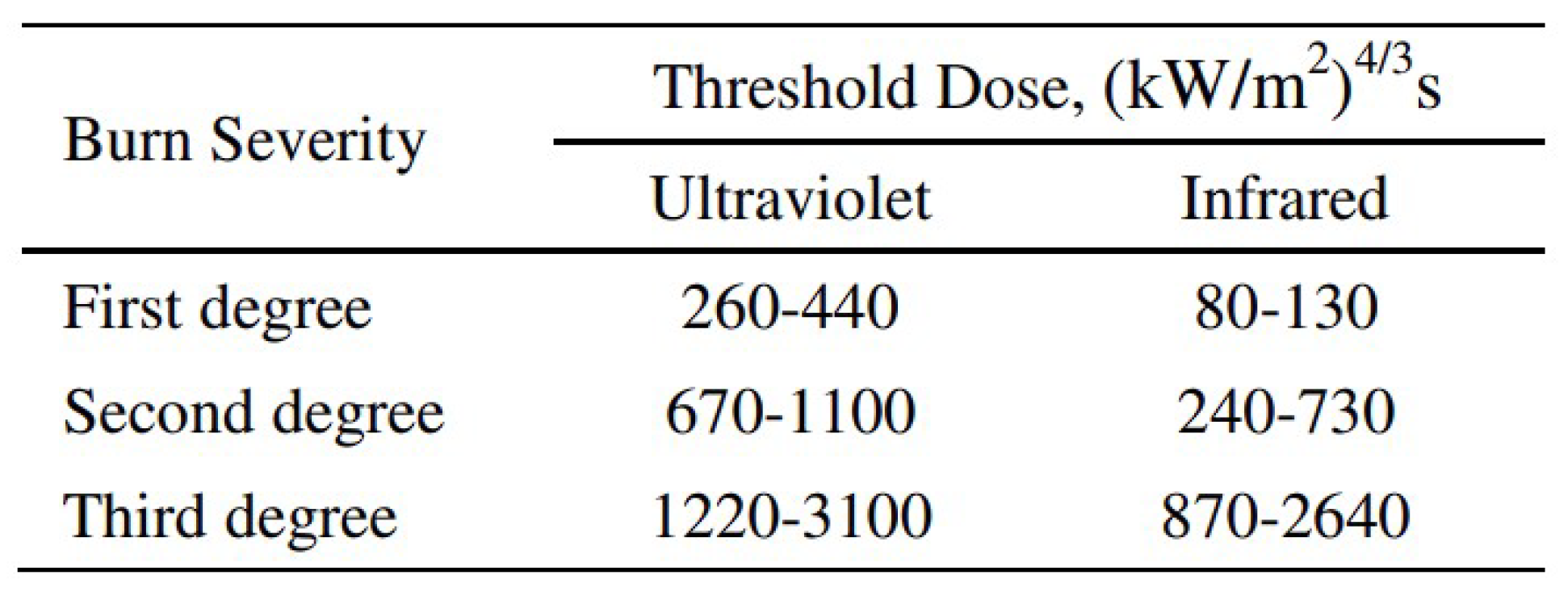
The release domain and setup used for the computations in this work are displayed in Figure 46 [123], along with the resulting thermal dose distributions at different times for one of the test cases. The release temperature for this test was 78 K and the pressure was 4 bar, with a mass flow rate of 0.56 g/s. The threshold thermal dose range for each burn degree for people not wearing protective clothing is displayed in Figure 47 [123].
Using these threshold levels and the resulting CFD thermal dose distributions, the distances for each harm level from the release point were calculated for the flame length. These distances were presented in figures and tables, as found in [123]. The validation of this CFD tool through comparison to SNL experiments was undertaken in a previously released paper by Cirrone, Makarov and Molkov in [124].
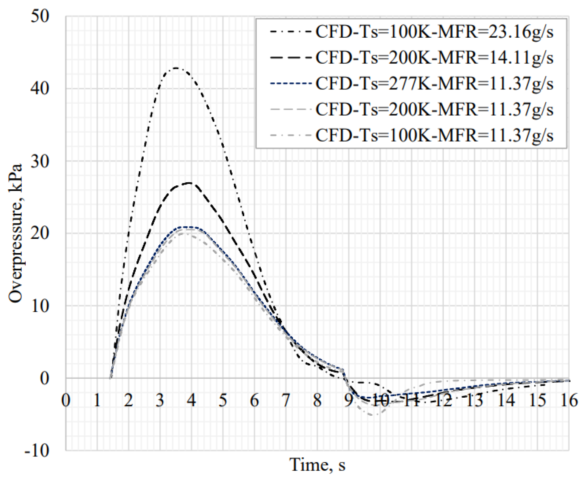
Cirrone et al. also carried out an investigation into the pressure peaking phenomena (PPP) for ignited hydrogen jets [125]. Ignited hydrogen releases into a storage enclosure with limited vent size such as a marine vessel or rail carriage were studied in this work. During these releases, a distinctive peak in pressure was observed that exceeded the steady-state pressure. This phenomenon was first identified by researchers at Ulster University during unignited releases of hydrogen in [126]. It was highlighted in this study that the these peaks in pressure in an enclosure could result in the destruction of civil structures, with peaks in the magnitude range of 10–20 kPa. However, the PPP would be more significant for ignited releases of hydrogen. A validated CFD model was used to simulate ignited cryogenic hydrogen releases from storage pressures of up to 12.4 MPa into a larger-scale enclosure of 15 m3, using the RANS governing equations and EDC model for combustion. The notional nozzle and volumetric source models were both tested and compared. It was found that the volumetric source model resulted in a three-fold reduction in computational cost with respect to the notional nozzle theory. The PPP can be observed in Figure 48, which displays the effect of varying cryogenic storage temperatures on the overpressure during ignited releases into an enclosure with three vents.
From these results, it was found that a decrease in storage temperature at a constant storage pressure and discharge coefficient resulted in an increased exit mass flow rate, causing a greater peak in overpressure. This validated CFD code can be used as a time-efficient safety tool in the future.
An investigation into the effect of accounting for heat transfer through the release pipe walls on the numerical simulations of cryogenic hydrogen jet fires was performed by Cirrone et al. [127]. By including heat transfer through the release pipe in a separate CFD simulation, the temperature at the real nozzle exit was increased from 67 K to a range of 98–127 K, dependent on the storage conditions. This CFD study used an LES explicit density-based solver, with the computational domain as shown in Figure 49.
Using the resulting adjusted real nozzle exit conditions from Figure 50, the notional nozzle exit conditions were calculated using the Abel–Noble EoS and implemented into the CFD model for ignited hydrogen jet fires. This CFD model was validated in [124] against vertical release experiments by SNL, as described earlier in this section. However, the model was further validated against horizontal release experiments performed at KIT in the current study. The resulting ignited cryogenic jet flame can be seen in [127], which accounts for heat transfer in the pipe as in Figure 50. The temperature, OH mole fraction and H20 mole fraction distribution were presented. As a result of the combustion products, buoyancy was seen to influence the flame, reducing the associated temperature hazard distances.

5. Conclusions

5.1. Summary and Current Progress

This paper provides a comprehensive overview of the progress of current research into cryogenic hydrogen jet and flame applications. The background and motivation for the use of green hydrogen as an alternative fuel for the future was first emphasised. Then, an overview of theoretical concepts, physics and integral models was presented. The numerous experimental releases performed by different institutions across the world, including SNL, KIT, HSE, NASA and NEDO and others, were described in detail. Following this, the numerical studies that aimed to simulate these unignited and ignited hydrogen release experiments were reviewed. The CFD codes developed through these simulations were validated through comparison to the described experiments. Multiple CFD codes implemented different governing equations, sub-models and equations of state, dependent on their application. The computational codes discussed have been employed to investigate a wide range of phenomena that are crucial to the safe storage and distribution of hydrogen. Examples of these phenomena include the occurrence of pressure peaks within confined enclosures, spontaneous ignition, the development of shock wave structures, buoyancy, atomisation and liquefaction/solidification. A thorough understanding of these phenomena is essential to mitigate the risks associated with hydrogen storage and distribution. Notably, many of the numerical and experimental studies conducted in this field have gathered data on the concentration of hydrogen, a key parameter in ensuring storage safety, as it provides insight into the flammable region that may arise in the event of accidental leaks.

5.2. Challenges for Future Research

With respect to challenges and potential for future research, there generally seems to be a lack of study on the near-field flow physics of cryogenic hydrogen jets, and flames in particular. The majority of current work focuses on the far-field jet and flame properties, characterisation and the associated safety considerations.

5.2.1. Experiments

Performing experiments to investigate cryogenic and liquid hydrogen jets and flames under both unignited and ignited conditions presents several challenges. The handling and storage of cryogenic and liquid hydrogen requires specialised equipment and strict safety protocols to prevent ignition and ensure worker safety. Generating and stabilising a cryogenic or liquid hydrogen jet is difficult due to the low viscosity and low density of hydrogen, which can cause jet break-up and instability. Furthermore, igniting a cryogenic or liquid hydrogen jet requires precise control over the fuel and oxidiser mixtures, which can be challenging. Measuring the properties of the jet, such as its temperature and velocity, presents additional difficulties due to the low density and low viscosity of hydrogen. In addition, the use of cryogenic or liquid hydrogen can be expensive due to the cost of producing and handling the fuel, as well as the infrastructure required to support its use. Finally, while cryogenic and liquid hydrogen themselves are not greenhouse gases, their production and use can contribute to greenhouse gas emissions if proper measures are not taken to ensure that they are produced and used in an environmentally sustainable manner. Despite these challenges, the use of cryogenic and liquid hydrogen for jet and flame experiments is critical in advancing our understanding of combustion processes and has the potential to lead to the development of more efficient and cleaner-energy technologies.

5.2.2. Numerical Simulations

Computational fluid dynamics (CFD) simulations of cryogenic hydrogen jets and flames also pose several challenges for future research. Cryogenic hydrogen’s unique properties, such as its low density, viscosity and phase change behaviour, make its accurate representation in numerical simulations difficult. Moreover, the high computational cost of simulating cryogenic hydrogen flows can also be a limiting factor, especially for three-dimensional simulations and direct numerical simulations. Another challenge in numerical simulations is validating the results against experimental data, as obtaining experimental data for cryogenic hydrogen flows can be difficult and expensive, as previously described above. It was pointed out in [115] that predicting the near-field flow of liquid hydrogen releases using a CFD tool is a challenge. This was stated due to the associated phenomena being highly complex and there being a lack of proper related experiments, making it difficult to verify the precision of such a tool. Furthermore, the phase changes of liquid and cryogenic hydrogen jets can have a significant impact on the behaviour of the flow, and accurately modelling this phenomenon is a key challenge in CFD simulations. As a result, care must be taken when selecting suitable sub-models and equations. Furthermore, correctly modelling turbulence is still a major challenge in modern CFD. Direct numerical simulation (DNS) is the most accurate method in predicting turbulence and is capable of capturing the entire scale of turbulence, through the use of exceptionally fine computational meshes. As a result of this, it is limited to low Reynolds number simulations with very small design domains. Perhaps, as the computational resources and technology continue to improve, DNS will become applicable to larger domains. However, at this stage, there are alternative methods used to approximate turbulence. These include models such as large-eddy simulation (LES) and Reynolds-averaged Navier–Stokes (RANS) turbulence models. Similarly to modelling turbulence, the required mesh resolution to capture deflagration to detonation transition (DDT) and spontaneous ignition is extremely small. As a result, it is currently unfeasible to model these phenomena when simulating larger-scale industrial applications. Additional general challenges and disadvantages of using CFD include the need for expensive computational resources, the complexity of models and equations and the potential for errors and uncertainties in the results. Despite these challenges, CFD simulations can be more time-efficient, cost-efficient and safer when compared to experiments. They also allow for a deeper understanding of the problem through detailed insights and visualisation of the results, which can be difficult to obtain from experimentation alone. The following are some suggested gaps to be addressed in future research on cryogenic hydrogen jet and flame simulations, based on the completion of this review paper:
  • There is a lack of a database containing all hydrogen release experiments for numerical model validation;
  • There are few simulations carried out on real, industrial-scale problems with complex geometry and variable weather conditions;
  • There are few studies on highly underexpanded hydrogen jets;
  • There are few studies on multiphase hydrogen jets;
  • There are few studies that account for the non-ideal behaviour of liquid and gaseous hydrogen at very low temperatures;
  • There are few studies that investigate indoor confined hydrogen flames and fires;
  • There does not exist a CFD model evaluation and validation protocol for hydrogen safety that is similar to that for liquefied natural gas (LNG) [128].

Funding

This research received no external funding.

Conflicts of Interest

The authors declare no conflict of interest.

Abbreviations

The following abbreviations are frequently used in this manuscript:
LH2Liquid Hydrogen
EoSEquation of State
SNLSandia National Laboratories
KITKarlsruhe Institute of Technology
NASANational Aeronautics and Space Administration
CFDComputational Fluid Dynamics
RANSReynolds-Averaged Navier–Stokes
LESLarge-Eddy Simulation

References

  1. Callendar, G.S. The artificial production of carbon dioxide and its influence on temperature. J. R. Meteorol. Soc. 1938, 64, 223–240. [Google Scholar] [CrossRef]
  2. UK Government. Net Zero Strategy: Build Back Greener; UK Government: London, UK, 2021.
  3. Department for Transport. Jet Zero Consultation: Summary of Responses and Government Response; UK Government: London, UK, 2022.
  4. Department for Transport. Decarbonising Transport: A Better, Greener Britain; UK Government: London, UK, 2021.
  5. UK Government. UK Hydrogen Strategy; UK Government: London, UK, 2021.
  6. Crowl, D.; Jo, Y.-D. The hazards and risks of hydrogen. J. Loss Prev. Process. Ind. 2007, 20, 158–164. [Google Scholar] [CrossRef]
  7. Acar, C.; Dincer, I. Review and evaluation of hydrogen production options for better environment. J. Clean. Prod. 2019, 218, 835–849. [Google Scholar] [CrossRef]
  8. Acar, C.; Dincer, I. Review and evaluation of hydrogen production methods for better sustainability. Int. J. Hydrogen Energy 2015, 40, 11094–11111. [Google Scholar]
  9. Holladay, J.; Hu, J.; King, D.; Wang, Y. An overview of hydrogen production technologies. Catal. Today 2009, 139, 244–260. [Google Scholar] [CrossRef]
  10. Nikolaidis, P.; Poulikkas, A. A comparative overview of hydrogen production processes. Renew. Sustain. Energy Rev. 2017, 67, 597–611. [Google Scholar] [CrossRef]
  11. Abdalla, A.M.; Hossain, S.; Nisfindy, O.B.; Azad, A.T.; Dawood, M.; Azad, A.K. Hydrogen production, storage, transportation and key challenges with applications: A review. Energy Conserv. Manag. 2018, 165, 602–627. [Google Scholar] [CrossRef]
  12. Watson, E. The First Hydrogen Balloon. Eng. Sci. 1946, 9, 12–16. [Google Scholar]
  13. Eckener, H. Count Zeppelin: The Man and His Work; Massie Publishing Company Limited: Auckland, New Zealand, 1938. [Google Scholar]
  14. DiLisi, G. The Hindenburg Disaster: Combining Physics and History in the Laboratory. Phys. Teach. 2017, 55, 268–273. [Google Scholar] [CrossRef]
  15. Mattingly, J. Elements of Gas Turbine Propulsion; McGraw-Hill: New York, NY, USA, 2017; Volume 1. [Google Scholar]
  16. Sloop, J. Liquid Hydrogen as a Propulsion Fuel, 1945–1959; Scientific and Technical Information Office, NASA: Hampton, VI, USA, 1978; Volume 4404.
  17. Heald, D. 50 Years of Atlas Propulsion Systems. In Proceedings of the 44th AIAA/ASME/SAE/ASEE Joint Propulsion Conference & Exhibit, Hartford, CT, USA, 21–23 July 2008; Volume 44, p. 5223. [Google Scholar]
  18. Khandelwal, B. Hydrogen powered aircraft: The future of air transport. Prog. Aerosp. Sci. 2013, 60, 45–59. [Google Scholar] [CrossRef]
  19. Heinz, G.; Faass, K. CRYOPLANE: Hydrogen fuelled aircraft—Status and challenges. Air Space Eur. 2001, 3, 252–254. [Google Scholar]
  20. Boyce, R.; Gerard, S.; Paull, A. The HyShot Scramjet Flight Experiment—Flight Data and CFD Calculations Compared. AIAA Int. Space Planes Hypersonic Syst. Technol. 2003, 12, 7029. [Google Scholar]
  21. McClinton, C. Preliminary X-43 flight test results. Acta Astronaut. 2005, 57, 266–276. [Google Scholar] [CrossRef]
  22. Mills, G.; Buchholtz, B.; Olsen, A. Design, fabrication and testing of a liquid hydrogen fuel tank for a long duration aircraft. AIP Conf. Proc. 2012, 1434, 773–780. [Google Scholar]
  23. Yilmaz, I. Investigation of hydrogen usage in aviation industry. Energy Conserv. Manag. 2012, 63, 63–69. [Google Scholar] [CrossRef]
  24. Bruce, S.; Temminghoff, M.; Hayward, J.; Palfreyman, D.; Munnings, C.; Burke, N.; Creasey, S. Opportunities for Hydrogen in Aviation; CSIRO: Canberra, NSW, Australia, 2020.
  25. Bicer, Y.; Dincer, I. Life cycle evaluation of hydrogen and other potential fuels for aircrafts. Int. J. Hydrogen Energy 2017, 42, 10722–10738. [Google Scholar] [CrossRef]
  26. Contreras, A. Hydrogen as aviation fuel: A comparison with hydrocarbon fuels. Int. J. Hydrogen Energy 1997, 22, 1053–1060. [Google Scholar] [CrossRef]
  27. Baroutaji, A.; Wilberforce, T.; Ramadan, M.; Olabi, A.G. Comprehensive investigation on hydrogen and fuel cell technology in the aviation and aerospace sectors. Renew. Sustain. Energy Rev. 2019, 106, 31–40. [Google Scholar] [CrossRef]
  28. Petrescu, R.; Machin, A.; Fontanez, K.; Arango, J.C.; Marquez, F.M.; Petrescu, F.I.T. Hydrogen for aircraft power and propulsion. Int. J. Hydrogen Energy 2020, 45, 20740–20764. [Google Scholar] [CrossRef]
  29. Rondinelli, S.; Gardi, A.; Kapoor, R.; Sabatini, R. Benefits and challenges of liquid hydrogen fuels in commercial aviation. Int. J. Sustain. Aviat. 2017, 3, 200–211. [Google Scholar] [CrossRef]
  30. Hua, T.; Ahluwalia, R.K.; Peng, J.K.; Kromer, M.; Lasher, S.; McKenney, K.; Law, K.; Sinha, J. Technical assessment of compressed hydrogen storage tank systems for automotive applications. Int. J. Hydrogen Energy 2011, 36, 3037–3049. [Google Scholar] [CrossRef]
  31. Yanxing, Z.; Maoqiong, G.; Yuan, Z.; Xueqiang, D.; Jun, S. Thermodynamics analysis of hydrogen storage based on compressed gaseous hydrogen, liquid hydrogen and cryo-compressed hydrogen. Int. J. Hydrogen Energy 2019, 44, 16833–16840. [Google Scholar] [CrossRef]
  32. Aceves, S.; Petitpas, G.; Espinosa-Loza, F.; Matthews, M.J.; Ledesma-Orozco, E. Safe, long range, inexpensive and rapidly refuelable hydrogen vehicles with cryogenic pressure vessels. Int. J. Hydrogen Energy 2013, 38, 2480–2489. [Google Scholar] [CrossRef]
  33. Ahluwalia, R.; Hua, T.Q.; Peng, J.K.; Lasher, S.; McKenney, K.; Sinha, J.; Gardiner, M. Technical assessment of cryo-compressed hydrogen storage tank systems for automotive applications. Int. J. Hydrogen Energy 2010, 35, 4171–4184. [Google Scholar] [CrossRef]
  34. Petitpas, G.; Aceves, S. Modeling of sudden hydrogen expansion from cryogenic pressure vessel failure. Int. J. Hydrogen Energy 2013, 38, 8190–8198. [Google Scholar] [CrossRef]
  35. Winnefeld, C.; Kadyk, T.; Bensmann, B.; Krewer, U.; Hanke-Rauschenbach, R. Modelling and Designing Cryogenic Hydrogen Tanks for Future Aircraft Applications. Energies 2018, 11, 105. [Google Scholar] [CrossRef]
  36. Sorensen, B. Hydrogen and Fuel Cells: Emerging Technologies and Applications; Academic Press: Cambridge, MA, USA, 2018; Volume 3. [Google Scholar]
  37. Abohamzeh, E. Review of hydrogen safety during storage, transmission, and applications processes. J. Loss Prev. Process. Ind. 2021, 72, 104569. [Google Scholar] [CrossRef]
  38. Groth, K.; Hecht, E. HyRAM: A methodology and toolkit for quantitative risk assessment of hydrogen systems. Int. J. Hydrogen Energy 2017, 42, 7485–7493. [Google Scholar] [CrossRef]
  39. Franquet, E.; Perrier, V.; Gibout, S.; Bruel, P. Free underexpanded jets in a quiescent medium: A review. Prog. Aerosp. Sci. 2015, 77, 25–53. [Google Scholar] [CrossRef]
  40. Cumber, P.; Fairweather, M.; Falle, S.A.E.G.; Giddings, J.R. Predictions of the structure of turbulent, moderately underexpanded jets. J. Fluids Eng. 1994, 116, 707–713. [Google Scholar] [CrossRef]
  41. Cumber, P.; Fairweather, M.; Falle, S.A.E.G.; Giddings, J.R. Predictions of the structure of turbulent, highly underexpanded jets. J. Fluids Eng. 1995, 117, 599–604. [Google Scholar] [CrossRef]
  42. Ewan, B.; Moodie, K. Structure and velocity measurements in underexpanded jets. Combust. Sci. Technol. 1986, 45, 275–288. [Google Scholar] [CrossRef]
  43. Winters, W. Modeling Leaks from Liquid Hydrogen Storage Systems; Sandia National Laboratories: Albuquerque, NM, USA, 2009.
  44. Winters, W.; Houf, W. Simulation of small-scale releases from liquid hydrogen storage systems. Int. J. Hydrogen Energy 2011, 36, 3913–3921. [Google Scholar] [CrossRef]
  45. Schefer, R.; Houf, W. Analytical and experimental investigation of small-scale unintended releases of hydrogen. Int. J. Hydrogen Energy 2008, 33, 1435–1444. [Google Scholar]
  46. Winters, W.; Evans, G. Final Report for the ASC Gas-Powder Two-Phase Flow Modeling Project AD2006-09; Sandia National Laboratories: Albuquerque, NM, USA, 2007.
  47. Winters, W.; Houf, W. Simulation of High-Pressure Liquid Hydrogen Releases; Sandia National Laboratories: Albuquerque, NM, USA, 2013.
  48. Xiao, J.; Travis, J.; Breitung, W. Hydrogen release from a high pressure gaseous hydrogen reservoir in case of a small leak. Int. J. Hydrogen Energy 2011, 36, 2545–2554. [Google Scholar] [CrossRef]
  49. Venetsanos, A.; Cirrone, D.; Coldrick, S.; Giannissi, S.; Jordan, T.; Mauri, L.; Molkov, V.; Xiao, J. Theory and Analysis of Cryogenic Hydrogen Release and Dispersion. Preshly Deliv. D 2019, 3, 1. [Google Scholar]
  50. Lyons, K. Theory and analysis of ignition with specific conditions related to cryogenic hydrogen. Preshly 2020. [Google Scholar]
  51. Correa-Jullian, C.; Groth, K. Data requirements for improving the Quantitative Risk Assessment of liquid hydrogen storage systems. Int. J. Hydrogen Energy 2022, 47, 4222–4235. [Google Scholar] [CrossRef]
  52. Cirrone, D.; Makarov, D.; Friedrich, A.; Grune, J.; Takeno, K.; Molkov, V. Blast Wave Generated by Delayed Ignition of Under-Expanded Hydrogen Free Jet at Ambient and Cryogenic Temperatures. Hydrogen 2022, 3, 433–449. [Google Scholar] [CrossRef]
  53. Hecht, E.; Panda, P. Ignition and flame characteristics of cryogenic hydrogen releases. Int. J. Hydrogen Energy 2017, 42, 775–785. [Google Scholar]
  54. Hecht, E.; Panda, P.; Chowdhury, B.; Ye, D. Characteristics of Cryogenic Hydrogen Releases Under Unignited and Ignited Conditions; Sandia National Laboratories: Albuquerque, NM, USA, 2019.
  55. Hecht, E.; Panda, P. Mixing and warming of cryogenic hydrogen releases. Int. J. Hydrogen Energy 2019, 44, 8960–8970. [Google Scholar] [CrossRef]
  56. Hecht, E.; Chowdhury, B. Dispersion of Cryogenic Hydrogen Through High-Aspect Ratio Nozzles; Sandia National Laboratories: Albuquerque, NM, USA, 2019.
  57. Li, X.; Yao, C.; Egbert, S.C.; He, Q.; Zhao, Z.; Christopher, D.M.; Hecht, E.S. Self-similar characteristics of underexpanded, cryogenic hydrogen and methane jets. Int. J. Hydrogen Energy 2023, 48, 4104–4117. [Google Scholar] [CrossRef]
  58. Veser, A.; Kuznetsov, M.; Fast, G.; Friedrich, A.; Kotchourko, N.; Stern, G.; Schwall, M.; Breitung, W. The structure and flame propagation regimes in turbulent hydrogen jets. Int. J. Hydrogen Energy 2010, 36, 2351–2359. [Google Scholar] [CrossRef]
  59. Klinge, F.; Kirmse, T.; Kompenhans, J. Application of quantitative background oriented schlieren (BOS). In Proceedings of the PSFVIP-4, Chamonix, France, 3–5 June 2003; Volume 4097, pp. 3–5. [Google Scholar]
  60. Grant, I. Particle image velocimetry: A review. Proc. Inst. Mech. Eng. Part J. Mech. Eng. Sci. 2016, 211, 55–76. [Google Scholar] [CrossRef]
  61. Friedrich, A. Ignition and heat radiation of cryogenic hydrogen jets. Int. J. Hydrogen Energy 2012, 37, 17589–17598. [Google Scholar] [CrossRef]
  62. Kobayashi, H. Experiment of cryo-compressed (90-MPa) hydrogen leakage diffusion. Int. J. Hydrogen Energy 2018, 43, 17928–17937. [Google Scholar] [CrossRef]
  63. Kobayashi, H. Experimental study on cryo-compressed hydrogen ignition and flame. Int. J. Hydrogen Energy 2020, 45, 5098–5109. [Google Scholar] [CrossRef]
  64. Hooker, P.; Willoughby, D.; Royle, M. Experimental Releases of Liquid Hydrogen. In Proceedings of the International Conference on Hydrogen Safety, San Francisco, CA, USA, 12–14 September 2011. [Google Scholar]
  65. Hooker, P.; Willoughby, D.; Hall, J. Ignited releases of liquid hydrogen: Safety considerations of thermal and overpressure effects. Int. J. Hydrogen Energy 2014, 39, 20547–20553. [Google Scholar]
  66. Cassutt, L.; Maddocks, F.; Sawyer, W. A study of the hazards in the storage and handling of liquid hydrogen. Adv. Cryog. Eng. 1960, 55–61. [Google Scholar]
  67. Witcofski, R.; Chirivella, J. Experimental and analytical analyses of the mechanisms governing the dispersion of flammable clouds formed by liquid hydrogen spills. Int. J. Hydrogen Energy 1984, 9, 425–435. [Google Scholar] [CrossRef]
  68. Nakamichi, K.; Kihara, Y.; Okamura, T. Observation of liquid hydrogen jet on flashing and evaporation characteristics. Cryogenics 2007, 48, 26–30. [Google Scholar] [CrossRef]
  69. Gong, L.; Yang, S.; Han, Y.; Jin, K.; Lu, L.; Gao, Y.; Zhang, Y. Experimental investigation on the dispersion characteristics and concentration distribution of unignited low-temperature hydrogen release. Process. Saf. Environ. Prot. 2022, 160, 676–682. [Google Scholar] [CrossRef]
  70. Yu, X.; Wu, Y.; Zhao, Y.; Wang, C. Flame characteristics of under-expanded, cryogenic hydrogen jet fire. Combust. Flame 2022, 244, 112294. [Google Scholar] [CrossRef]
  71. Mironov, V.; Penyazkov, O.; Ignatenko, D. Self-ignition and explosion of a 13-MPa pressurized unsteady hydrogen jet under atmospheric conditions. Int. J. Hydrogen Energy 2015, 40, 5749–5762. [Google Scholar] [CrossRef]
  72. Kitabayashi, N.; Wada, Y.; Mogi, T.; Saburi, T.; Hayashi, A.K. Experimental study on high pressure hydrogen jets coming out of tubes of 0.1–4.2 m in length. Int. J. Hydrogen Energy 2013, 38, 8100–8107. [Google Scholar] [CrossRef]
  73. Duan, Q.; Xiao, H.; Gao, W.; Wang, Q.; Shen, X.; Jiang, L.; Sun, J. An experimental study on shock waves and spontaneous ignition produced by pressurized hydrogen release through a tube into atmosphere. Int. J. Hydrogen Energy 2015, 40, 8281–8289. [Google Scholar] [CrossRef]
  74. Kessler, A.; Schreiber, A.; Wassmer, C.; Deimling, L.; Knapp, S.; Weiser, V.; Sachsenheimer, K.; Langer, G.; Eisenreich, N. Ignition of hydrogen jet fires from high pressure storage. Int. J. Hydrogen Energy 2014, 39, 20554–20559. [Google Scholar] [CrossRef]
  75. Fortov, V. Thermodynamics and Equations of State for Matter: From Ideal Gas to Quark-Gluon Plasma; World Scientific: Singapore, 2016. [Google Scholar]
  76. Chiapolino, A.; Boivin, P.; Saurel, R. A simple phase transition relaxation solver for liquid–vapor flows. Int. J. Numer. Methods Fluids 2016, 83, 583–605. [Google Scholar] [CrossRef]
  77. Wangxia, W.; Bing, W.; Gaoming, X. Impingement of high-speed cylindrical droplets embedded with an air/vapour cavity on a rigid wall: Numerical analysis. J. Fluid Mech. 2019, 864, 1058–1087. [Google Scholar]
  78. Menikoff, R.; Plohr, B. The Riemann problem for fluid flow of real materials. Rev. Mod. Phys. 1989, 61, 75. [Google Scholar] [CrossRef]
  79. Aslani, M.; Regele, J. A localized artificial diffusivity method to simulate compressible multiphase flows using the stiffened gas equation of state. Int. J. Numer. Methods Fluids 2018, 88, 413–433. [Google Scholar] [CrossRef]
  80. Haller, K.; Ventikos, Y.; Poulikakos, D. Wave structure in the contact line region during high speed droplet impact on a surface: Solution of the Riemann problem for the stiffened gas equation of state. J. Appl. Phys. 2003, 93, 3090–3097. [Google Scholar] [CrossRef]
  81. Neron, L.; Saurel, R. Noble-Abel/First-order virial equations of state for gas mixtures resulting of multiple condensed reactive materials combustion. Phys. Fluids 2021, 34, 016107. [Google Scholar] [CrossRef]
  82. Johnston, I. The Noble-Abel Equation of State: Thermodynamic Derivations for Ballistics Modelling; Defence Science and Technology Organisation Edinburgh Weapons Systems Division: Edinburgh, SA, Australia, 2005.
  83. Métayer, O.; Saurel, R. The Noble-Abel Stiffened-Gas equation of state. Phys. Fluids 2016, 28, 046102. [Google Scholar] [CrossRef]
  84. Métayer, O.; Saurel, R. Extended Noble—Abel Stiffened-Gas Equation of State for Sub-and-Supercritical Liquid-Gas Systems Far from the Critical Point. Fluids 2018, 3, 48. [Google Scholar]
  85. Redlich, O.; Kwong, J. On the thermodynamics of solutions. An equation of state: Fugacity of gaseous solutions. Chem. Rev. 1949, 44, 233–244. [Google Scholar] [CrossRef]
  86. Soave, G. Equilibrium constants from a modified Redlich-Kwong equation of state. Chem. Eng. Sci. 1972, 27, 1197–1203. [Google Scholar] [CrossRef]
  87. Peng, D.; Robinson, D. A new two-constant equation of state. Ind. Eng. Chem. Fundam. 1976, 15, 59–64. [Google Scholar] [CrossRef]
  88. Patel, N.; Teja, A. A new cubic equation of state for fluids and fluid mixtures. Chem. Eng. Sci. 1982, 37, 463–473. [Google Scholar] [CrossRef]
  89. Beattie, J.; Ikehara, S. An Equation of State for Gas Mixtures. II. A Study of the Methods of Combination of the Constants of the Beattie-Bridgeman Equation of State. Proc. Am. Acad. Arts Sci. 1930, 64, 127–176. [Google Scholar] [CrossRef]
  90. Mie, G. Zur kinetischen theorie der einatomigen körper. Ann. Phys. 1903, 316, 657–697. [Google Scholar] [CrossRef]
  91. Gruneisen, E. Theorie des festen zustandes einatomiger elemente. Ann. Phys. 1912, 344, 257–306. [Google Scholar] [CrossRef]
  92. Leachman, J.W.; Jacobsen, R.T.; Penoncello, S.; Lemmon, E.W. Fundamental Equations of State for Parahydrogen, Normal Hydrogen, and Orthohydrogen. J. Phys. Chem. Ref. Data 2009, 38, 721–748. [Google Scholar] [CrossRef]
  93. Saurel, R.; Petitpas, F.; Abgrall, R. Modelling phase transition in metastable liquids: Application to cavitating and flashing flows. J. Fluid Mech. 2008, 607, 313–350. [Google Scholar] [CrossRef]
  94. Zein, A. Numerical Methods for Multiphase Mixture Conservation Laws with Phase Transition. Doctoral Dissertation, Magdeburg University, Magdeburg, Germany, 2010. [Google Scholar]
  95. Downar-Zapolski, P.; Bilicki, Z.; Bolle, L.; Franco, J. The non-equilibrium relaxation model for one-dimensional flashing liquid flow. Int. J. Multiph. Flow 1996, 22, 473–483. [Google Scholar] [CrossRef]
  96. Chiapolino, A.; Boivin, P.; Saurel, R. A simple and fast phase transition relaxation solver for compressible multicomponent two-phase flows. Comput. Fluids 2017, 150, 31–45. [Google Scholar] [CrossRef]
  97. Boivin, P.; Cannac, M.; le Metayer, O. A thermodynamic closure for the simulation of multiphase reactive flows. Int. J. Therm. Sci. 2019, 137, 640–649. [Google Scholar] [CrossRef]
  98. Boivin, P.; Deng, X. Diffuse interface modelling of reactive multi-phase flows applied to a sub-critical cryogenic jet. Appl. Math. Model. 2020, 84, 405–424. [Google Scholar]
  99. Ren, Z.; Wen, J. Numerical characterization of underexpanded cryogenic hydrogen gas jets. AIP Adv. 2020, 10, 095303. [Google Scholar] [CrossRef]
  100. Ishimoto, J.; Ohira, K.; Okabayashi, K.; Chitose, K. Integrated numerical prediction of atomization process of liquid hydrogen jet. Cryogenics 2008, 48, 238–247. [Google Scholar] [CrossRef]
  101. Dou, Y.; Sun, L.; Ren, J.; Dong, L. Opportunities and future challenges in hydrogen economy for sustainable development. Hydrogen Econ. 2023, 1, 537–569. [Google Scholar]
  102. Ichard, M.; Hansen, O.R.; Middha, P.; Willoughby, D. CFD computations of liquid hydrogen releases. Int. J. Hydrogen Energy 2006, 37, 17380–17389. [Google Scholar] [CrossRef]
  103. Giannissi, S.G.; Venetsanos, A.G.; Markatos, N.; Bartzis, J.G. CFD modeling of hydrogen dispersion under cryogenic release conditions. Int. J. Hydrogen Energy 2014, 39, 15851–15863. [Google Scholar] [CrossRef]
  104. Giannissi, S.G.; Venetsanos, A.G.; Markatos, N. Modeling of cryogenic hydrogen jets. In Proceedings of the International Conference on Hydrogen Safety, Yokohama, Japan, 14–17 October 2015. [Google Scholar]
  105. Giannissi, S.G.; Venetsanos, A.G. Release and dispersion modeling of cryogenic under-expanded hydrogen jets. Int. J. Hydrogen Energy 2017, 42, 7672–7682. [Google Scholar]
  106. Giannissi, S.G.; Venetsanos, A.G. Study of key parameters in modeling liquid hydrogen release and dispersion in open environment. Int. J. Hydrogen Energy 2018, 43, 455–467. [Google Scholar] [CrossRef]
  107. Giannissi, S.G.; Venetsanos, A.G. A comparative CFD assessment study of cryogenic hydrogen and LNG dispersion. Int. J. Hydrogen Energy 2019, 44, 9018–9030. [Google Scholar] [CrossRef]
  108. Giannissi, S.G.; Venetsanos, A.G.; Hecht, E.S. Numerical predictions of cryogenic hydrogen vertical jets. Int. J. Hydrogen Energy 2021, 46, 12566–12576. [Google Scholar] [CrossRef]
  109. Jin, T.; Liu, Y.; Wei, J.; Wu, M.; Lei, G.; Chen, H.; Lan, Y. Modeling and analysis of the flammable vapor cloud formed by liquid hydrogen spills. Int. J. Hydrogen Energy 2017, 42, 26762–26770. [Google Scholar] [CrossRef]
  110. Jäkel, C.; Kelm, S.; Verfondern, K.; Allelein, H.-J. Validation of a 3D multiphase-multicomponent CFD model for accidental liquid and gaseous hydrogen releases. Int. J. Hydrogen Energy 2019, 44, 8807–8818. [Google Scholar] [CrossRef]
  111. Brennan, C. Fundamentals of Multiphase Flows; Cambridge University Press: Cambridge, UK, 2005. [Google Scholar]
  112. Qian, J.; Li, X.; Jin, Z. A numerical study of unintended hydrogen release in a hydrogen refueling station. Int. J. Hydrogen Energy 2020, 45, 20142–20152. [Google Scholar] [CrossRef]
  113. Schefer, R.; Houf, W.; Williams, T. Investigation of small-scale unintended releases of hydrogen: Momentum-dominated regime. Int. J. Hydrogen Energy 2008, 33, 6373–6384. [Google Scholar] [CrossRef]
  114. Swain, M.R.; Swain, M.N.; Grilliot, E.S. Risks Incurred by Hydrogen Escaping from Containers and Conduits; National Renewable Energy Lab: Golden, CO, USA, 1998.
  115. Hansen, O. Liquid hydrogen releases show dense gas behavior. Int. J. Hydrogen Energy 2020, 45, 1343–1358. [Google Scholar] [CrossRef]
  116. Ren, Z.; Giannissi, S.; Venetsanos, A.G.; Friedrich, A.; Kuznetsov, M.; Jordan, T.; Wen, J.X. The evolution and structure of ignited high-pressure cryogenic hydrogen jets. Int. J. Hydrogen Energy 2022, 47, 29184–29194. [Google Scholar] [CrossRef]
  117. Jordan, T.; Bernard, L.; Cirrone, D.; Coldrick, S.; Friedrich, A.; Jallais, S.; Kuznetsov, M.; Proust, C.; Venetsanos, A.G.; Wen, J.X. Results of the pre-normative research project PRESLHY for the safety use of liquid hydrogen. Preshly 2021. [Google Scholar]
  118. Keenan, J.; Makarov, D.; Molkov, V. Modelling and simulation of high-pressure hydrogen jets using notional nozzle theory and open source code OpenFOAM. Int. J. Hydrogen Energy 2017, 42, 7447–7456. [Google Scholar] [CrossRef]
  119. Yoshizawa, A. Bridging between eddy-viscosity-type and second-order turbulence models through a two-scale turbulence theory. Phys. Rev. 1993, 48, 273. [Google Scholar] [CrossRef]
  120. Parente, A.; Malik, M.R.; Contino, F.; Cuoci, A.; Dally, B.B. Extension of the Eddy Dissipation Concept for turbulence/chemistry interactions to MILD combustion. Fuel 2016, 163, 98–111. [Google Scholar] [CrossRef]
  121. Gong, L.; Li, Z.; Jin, K.; Gao, Y.; Duan, Q.; Zhang, Y.; Sun, J. Numerical study on the mechanism of spontaneous ignition of high-pressure hydrogen during its sudden release into a tube. Saf. Sci. 2020, 129, 104807. [Google Scholar] [CrossRef]
  122. Cirrone, D.; Makarov, D.; Molkov, V. Spontaneous ignition of cryo-compressed hydrogen in a T-shaped channel system. Hydrogen 2022, 3, 348–360. [Google Scholar] [CrossRef]
  123. Cirrone, D.; Makarov, D.; Molkov, V. Near field thermal dose of cryogenic hydrogen jet fires. Int. Semin. Fire Explos. Hazards 2019, 9, 1361–1367. [Google Scholar]
  124. Cirrone, D.; Makarov, D.; Molkov, V. Thermal radiation from cryogenic hydrogen jet fires. Int. J. Hydrogen Energy 2019, 44, 8874–8885. [Google Scholar] [CrossRef]
  125. Cirrone, D.; Makarov, D.; Lach, A.; Gaathaug, A.; Molkov, V. The Pressure Peaking Phenomenon for Ignited Under-Expanded Hydrogen Jets in the Storage Enclosure: Experiments and Simulations for Release Rates of up to 11.5 g/s. Energies 2022, 15, 271. [Google Scholar] [CrossRef]
  126. Brennan, S.; Molkov, V.; Makarov, D. The Pressure Peaking Phenomenon for ignited dynamics of flammable hydrogen-air mixture formation in an enclosure with a single vent. Proc. Int. Semin. Fire Explos. 2011, 6, 493–503. [Google Scholar]
  127. Cirrone, D.; Makarov, D.; Kuznetsov, M.; Friedrich, A.; Molkov, V. Effect of heat transfer through the release pipe on simulations of cryogenic hydrogen jet fires and hazard distances. Int. J. Hydrogen Energy 2022, 47, 21596–21611. [Google Scholar] [CrossRef]
  128. Ivings, M.J.; Jagger, S.F.; Lea, C.J.; Webber, D.M. Evaluating vapor dispersion models for safety analysis of LNG facilities. Fire Prot. Res. Found. 2016. [Google Scholar]
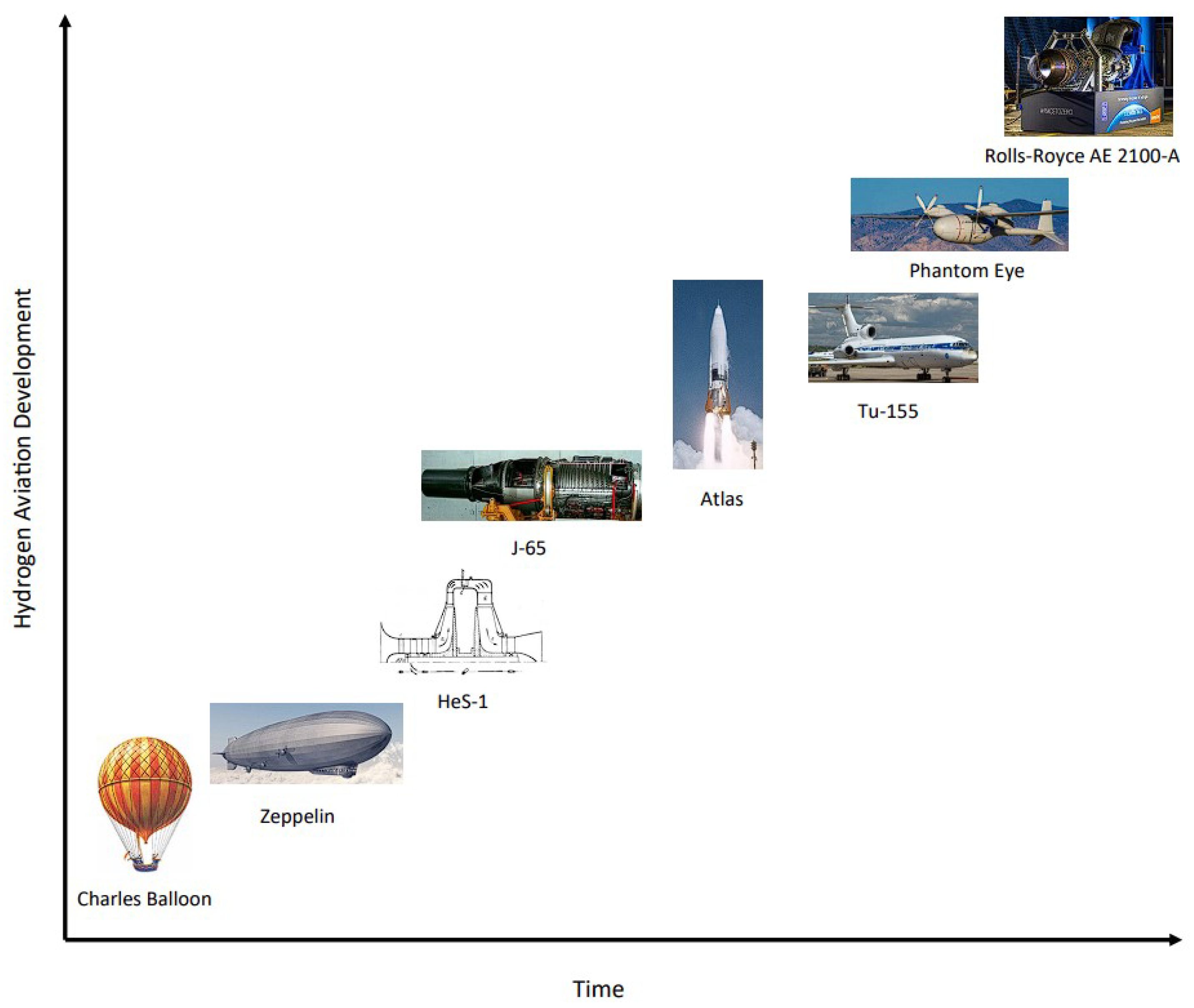
Figure 1. The development of hydrogen aviation technology over time.
Energies 16 04411 g001
Figure 2. Cryogenic pressure vessel configuration schematic [34].
Energies 16 04411 g002
Figure 3. Illustration of the underexpanded jet flow zones: near-field, transition and far-field [39].
Energies 16 04411 g003
Figure 4. Moderately underexpanded jet near-field shock structure [39].
Energies 16 04411 g004
Figure 5. Highly underexpanded jet near-field shock structure [41].
Energies 16 04411 g005
Figure 6. Very highly underexpanded jet near-field shock structure [42].
Energies 16 04411 g006
Figure 7. Slow leak system from liquid hydrogen tank [43].
Energies 16 04411 g007
Figure 8. The three zones for the slow leak turbulent entrainment models [43].
Energies 16 04411 g008
Figure 9. Zone 3 jet influenced by buoyancy coordinate system [43].
Energies 16 04411 g009
Figure 10. Fast leak system from liquid hydrogen tank [43].
Energies 16 04411 g010
Figure 11. Flow regime breakdown for Xiao, Travis and Breitung’s small leak model [48].
Energies 16 04411 g011
Figure 12. Cryogenic storage vessel model schematic [34].
Energies 16 04411 g012
Figure 13. Experimental system setup at the SNL Turbulent Combustion Laboratory [53].
Energies 16 04411 g013
Figure 14. Comparison of cryogenic hydrogen jet, using visible image (a) and IR image (b) [53].
Energies 16 04411 g014
Figure 15. Diagnostic experimental setup for the Raman spectroscopy [55].
Energies 16 04411 g015
Figure 16. Median values from 400 images (left), single image (right), hydrogen mole fraction (top), nitrogen mole fraction (middle), temperature (bottom) [54].
Energies 16 04411 g016
Figure 17. Comparison of original (left) and denoised (right) results for hydrogen jet mole fraction (top) and temperature (bottom) distributions [57].
Energies 16 04411 g017
Figure 18. BOS image of an unignited hydrogen jet from a 4 mm diameter nozzle at 10 bar [58].
Energies 16 04411 g018
Figure 19. Maximum distance for flame flashback prediction plot [61].
Energies 16 04411 g019
Figure 20. Experimental system setup at the KIT ICESAFE facility [61].
Energies 16 04411 g020
Figure 21. Experimental system setup at the NEDO facility [62].
Energies 16 04411 g021
Figure 22. Side view of cryogenic hydrogen jet at the NEDO test facility [62].
Energies 16 04411 g022
Figure 23. Ignition process of established cryogenic hydrogen jet [63].
Energies 16 04411 g023
Figure 24. Scale drawing of the flammability ranges and resulting secondary explosion due to ignited LH2 release [65].
Energies 16 04411 g024
Figure 25. Heat radiation measurements for ignited releases with secondary explosions present [65].
Energies 16 04411 g025
Figure 26. Image displaying the simulation boundary conditions and domain [99].
Energies 16 04411 g026
Figure 27. Density distribution transient development [99].
Energies 16 04411 g027
Figure 28. Hydrogen mass fraction transient development [99].
Energies 16 04411 g028
Figure 29. Non-dimensionalised pressure distribution transient development [99].
Energies 16 04411 g029
Figure 30. Schematic of the computational domain geometry used by Ishimoto et al. [100].
Energies 16 04411 g030
Figure 31. Comparison of CFD and experimental atomisation region results [100,101].
Energies 16 04411 g031
Figure 32. Qualitative comparison of CFD and experimental hydrogen cloud dispersion [103].
Energies 16 04411 g032
Figure 33. Schematic of the physical model geometry and domain [109].
Energies 16 04411 g033
Figure 34. Comparison of hydrogen concentration in CFD (right) and NASA (left) results [109].
Energies 16 04411 g034
Figure 35. Image of release area domain and layout [112].
Energies 16 04411 g035
Figure 36. Momentum–buoyancy-dominated hydrogen gas jet profile development [113].
Energies 16 04411 g036
Figure 37. Momentum-dominated hydrogen gas jet profile development [113].
Energies 16 04411 g037
Figure 38. Predicted hydrogen gas volume fraction distribution using FLACS [115].
Energies 16 04411 g038
Figure 39. Image of computational domain for hydrogen release simulation [116].
Energies 16 04411 g039
Figure 40. Transient development of temperature distribution, for ignition distance of 0.5 m from release location [116].
Energies 16 04411 g040
Figure 41. Transient development of OH radical distribution, for ignition distance of 0.5 m from release location [116].
Energies 16 04411 g041
Figure 42. Computational domain for the spontaneous hydrogen ignition study [121].
Energies 16 04411 g042
Figure 43. CFD temperature distributions in the tube for the initial stages after release [121].
Energies 16 04411 g043
Figure 44. CFD temperature distributions in the tube for the later stages [121].
Energies 16 04411 g044
Figure 45. Depiction of the spontaneous ignition mechanisms [121].
Energies 16 04411 g045
Figure 46. Computational domain thermal dose profiles for vertical release jet fire simulations [123].
Energies 16 04411 g046
Figure 47. Threshold thermal dose to categorise burn severity [123].
Energies 16 04411 g047
Figure 48. Effect of varying cryogenic storage temperature on the PPP [125].
Energies 16 04411 g048
Figure 49. Release pipe simulation computational domain (a) and mesh (b) [127].
Energies 16 04411 g049
Figure 50. Resulting adjusted nozzle exit temperature distributions from CFD [127].
Energies 16 04411 g050
Disclaimer/Publisher’s Note: The statements, opinions and data contained in all publications are solely those of the individual author(s) and contributor(s) and not of MDPI and/or the editor(s). MDPI and/or the editor(s) disclaim responsibility for any injury to people or property resulting from any ideas, methods, instructions or products referred to in the content.