2.1. Build FOC to PMSM
Through building a dq rotating rectangular coordinate system, which is on a rotor magnet, PMSM’s voltage vector is found in Equation [
10]:
where
Vq,
Vd are the PMSM d
q axis voltage component;
id,
iq is the d
q axis current component;
Ld,
Lq are the PMSM d
q axis inductance;
R1 is the phase resistance of the stator winding;
is the permanent magnet flux linkage; and
is the angle speed of the rotor.
Magnet torque produced by the PMSM:
where
is the motor poles pair. As we are going to use a surface-mounted magnet motor [
11], there is no salient effect, so we can control the exciting current on the above equation = 0, and the magnet torque can be simplified to be:
As one of the normal control methods for PMSM, the basic thought of field-oriented control (FOC) control is building a resolution of the motor’s three-phase alternating current (AC) voltage to
Vd and
Vq, and building a resolution of AC current to direct current (DC) components
id and
iq. The
iq corresponds to the motor’s torque current, and
id corresponds to the excitation current. So, the motor’s magnet torque can be controlled through the independent control of the torque current, which is simple and quick. The FOC control theory enhances AC motor control technology [
12] by leaps and bounds. In the constant airflow control system, FOC control is the bottom control unit; it is an indispensable part of the whole framework.
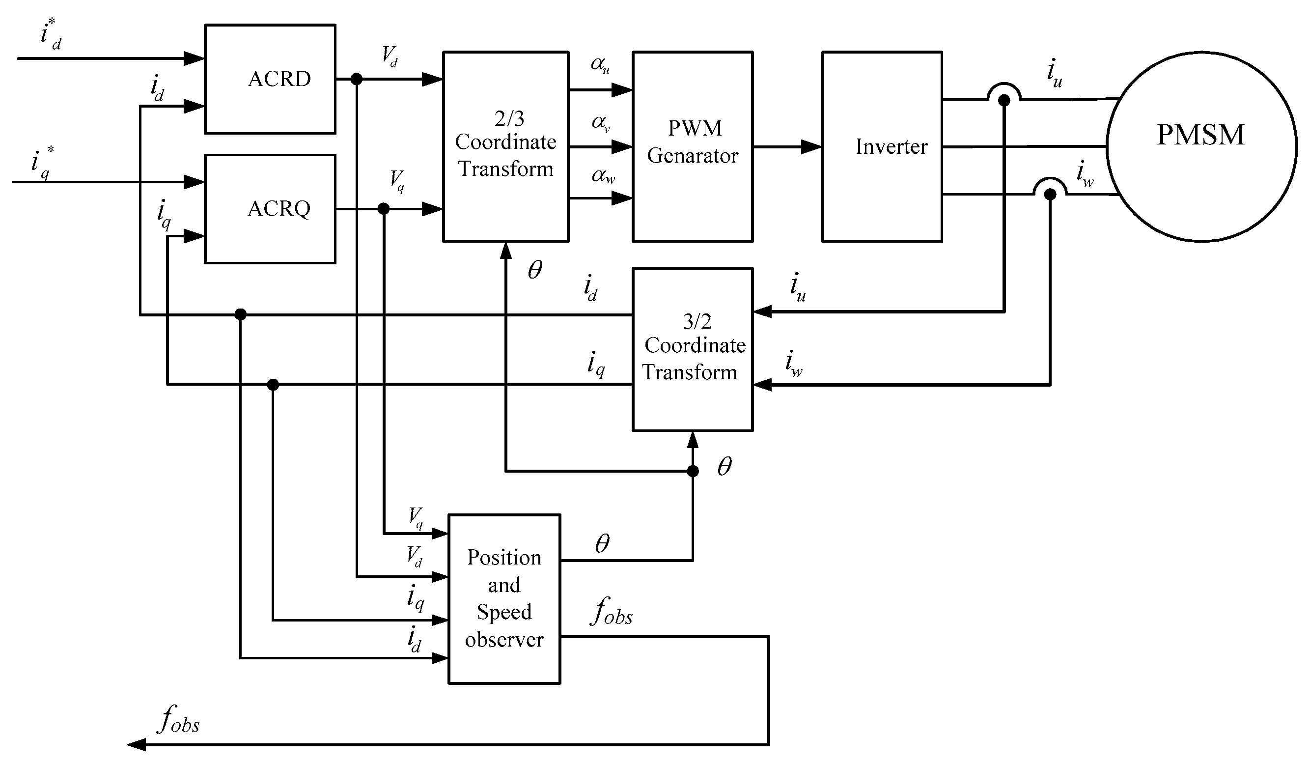
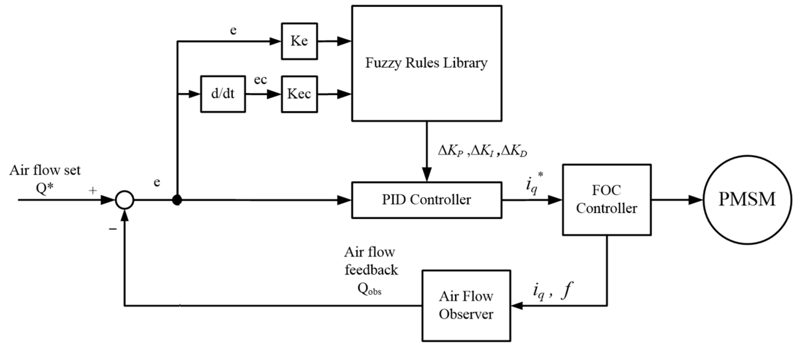
The sensorless FOC control schematics for PMSM are explained above in
Figure 2. First, obtain the motor rotor position through a speed and position observer, then obtain the phase angle of the motor, then the CPU samples the actual three-phase currents from the current sensor, then calculate the torque current
iq and the excitation current id through Clark and Park transformation of coordinates. Compare the set data and calculated data of the torque current
iq and the excitation current id separately, and obtain the voltages vector sum through input differences of the current comparisons with the current regulator. The voltage–duty ratio, which are outputs of the current regulator through inverse-Park and inverse-Clark coordinates transformed, are the inputs of the PWM waver generator. The generator produces six channels of PWM waves to control the insulated gate bipolar translator (IGBT) on/off and timing and control the motor effectively [
13].
From Equation (3), we can see the output electromagnet torques of the PMSM can be controlled by setting torque currents. If the torque current is constant, the output electromagnet torque of the PMSM motor is constant, too; this is called constant torque control [
14]. Obviously, the output of the airflow volume of the fan is not constant when the fan is controlled by constant torque controlling, so we need to research the torque currents controlling strategy when the fan is outputting constant airflow.
2.2. Design of the Airflow Observer
When the motor speed is constant, the output airflow
Q and air pressure
P’s relationship of the fan is as
Figure 3 explains. In
Figure 3, motor speed n
3 > n
2 > n
1, when the motor speed is at a certain fixed speed, airflow
Q changes when air pressure
P changes; this change makes a fixed QP curve, the curve changes when the motor speed changes, it makes one series of PQ curves. The line
Qc in
Figure 3 represents constant airflow that can be controlled by controlling the motor speed when the air pressure
P changes.
Equipping applications with airflow sensors makes the air supply system complex upon installation and increases the cost. In order to control the airflow constant, the air supply system needs to detect some other physical quantities which can be easily detected, such as motor current and motor rotation frequency, instead of airflow
Q detecting.
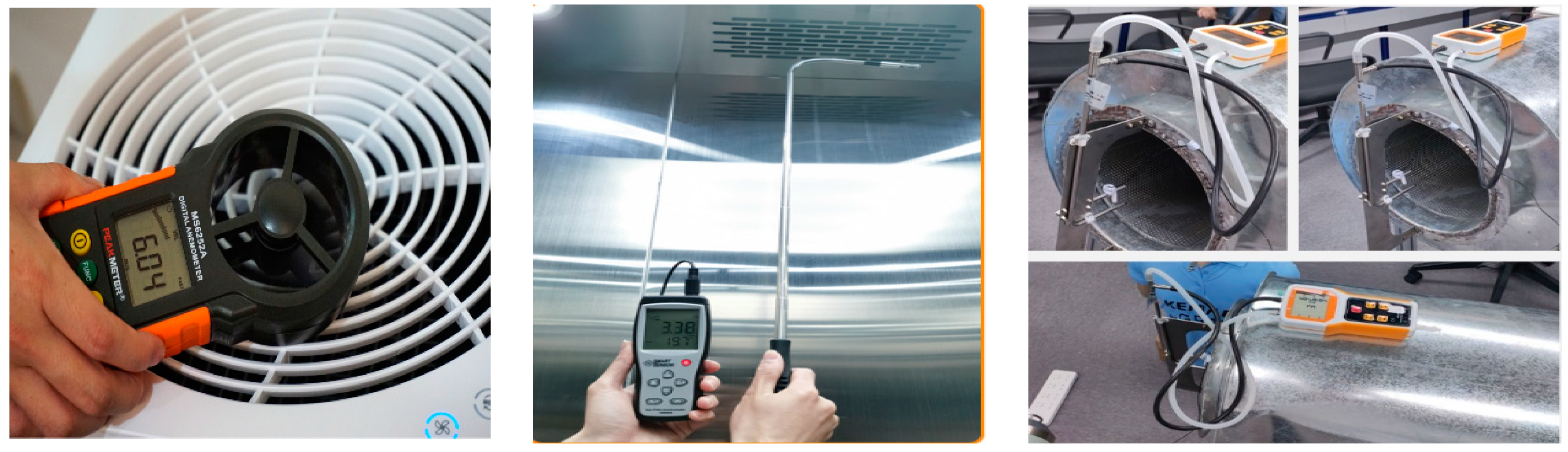
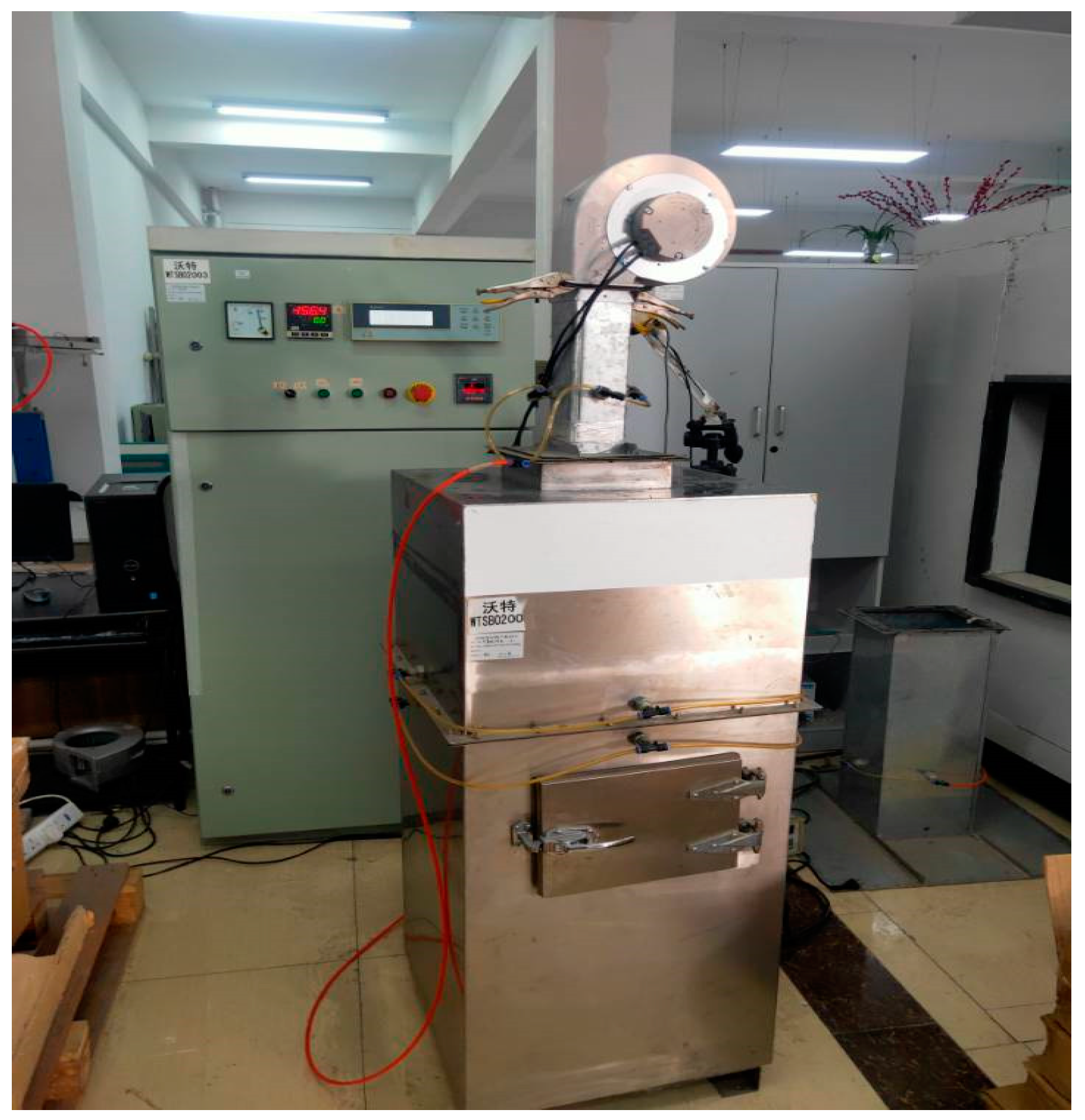
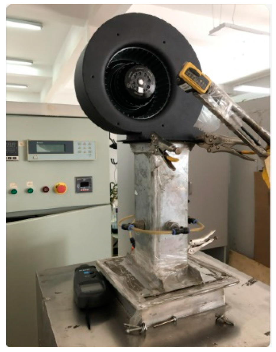
Figure 4 is an airflow testing chamber. In this airflow testing chamber, the air pressure
P can be adjusted by adjusting the drafting inductance fan inside or the air jet nozzle valves, the airflow of the fan can be measured at different air pressures in this testing chamber, displayed in
Figure 5.
The airflow testing schematic is shown below, where P1-Patm is the static pressure drop, and airflow volume is calculated through the pressure difference: Δ
P on the two sides of the nozzles. According to standards of AMCA210-995 [
15], air jet nozzles mouth size in OD: 10 mm, 30 mm, 40 mm, 50 mm, and 80 mm each one pc inside, one pressure transmitter: Yokogawa model EJA110, one pressure adjuster inside: Shemaden Model S10 inside. Moreover, the airflow volume testing theory formula is as follows:
where
Cd means Nozzle’s discharge co-efficiency [
16], An means Nozzle’s area,
β means dt/D,
Y means Expansion factor, calculated as:
where
γ means air-specific heat at constant pressure vs. constant volume heat capacity; normally, it is set at 1.4.
α means the ratio of static pressures on the inlet vs. outlet.
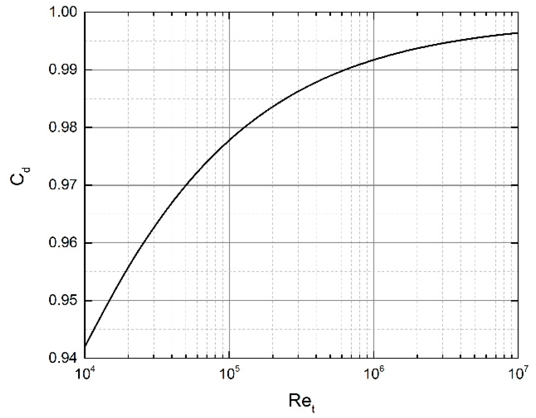
Figure 6 displays the relation of
Cd (discharge co-efficiency) and Reynolds number [
17], the airflow is calculated through the below process. First of all,
in
Figure 6 is computed in the following formula:
Then, we assumed
Cd as 0.9 [
18] and calculated
and
. Finally,
Cd in
Figure 6 is computed as follows:
This airflow volume chamber testing capacity is designed between 9M3/TO and 900 M3 per hour.
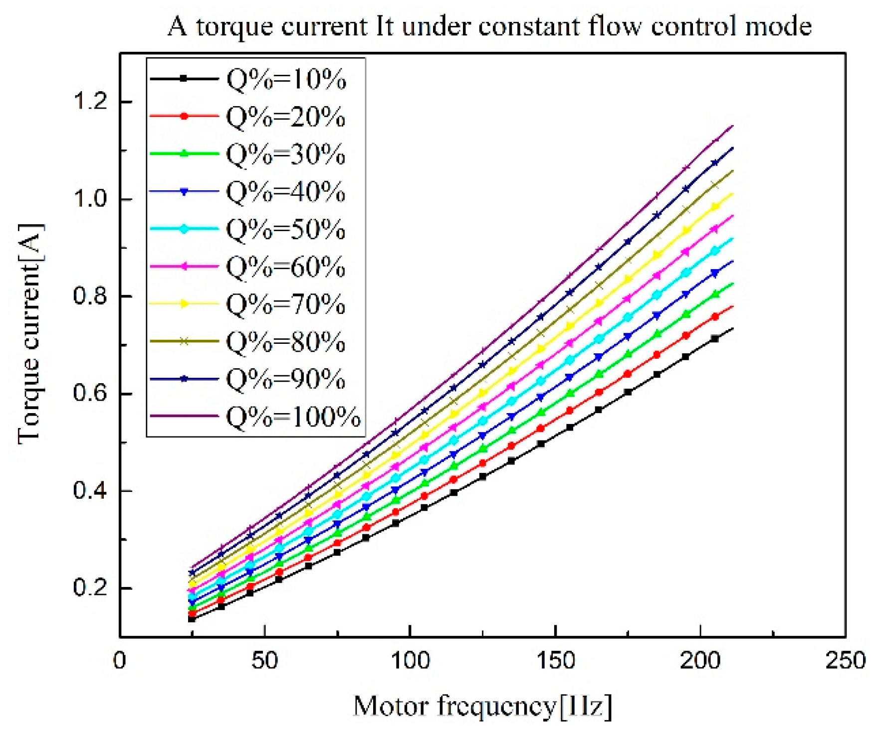
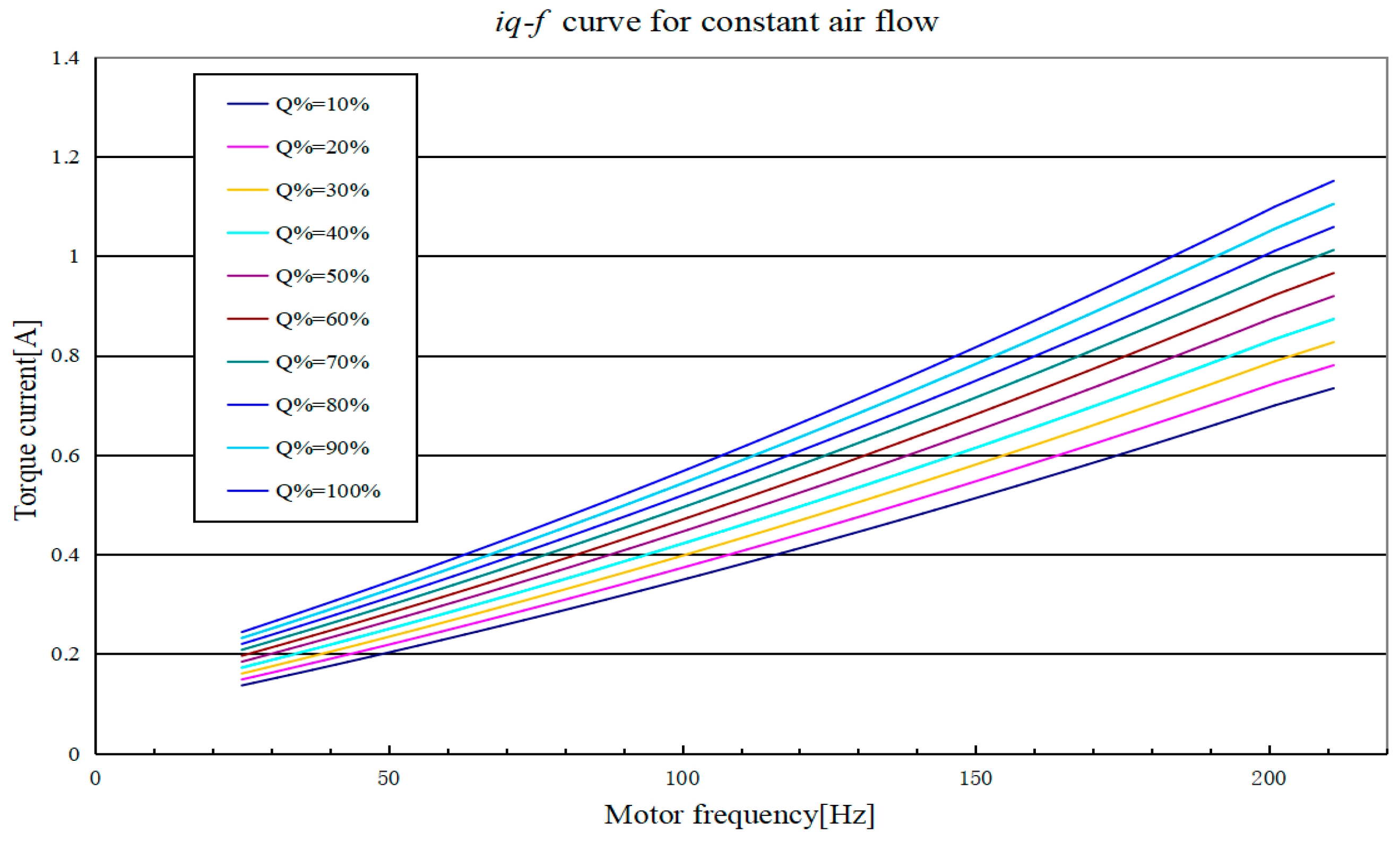
Using the
Figure 4 airflow testing chamber, we performed the below experiments. First, on the basis of
Figure 2 Fan’s PMSM FOC control, adding speed loops on the preceding stage, make a speed-controlled FOC control system, then we adjust the fan’s speed at different air pressures to make airflow always be certain data, then record the related torque current
iq and rotation frequency
f data. Through a large number of experiments, we finally found that when the airflow is constant data, adjust air pressure
P, when
P is higher, the motor’s rotation frequency
f is higher, which is more important, the torque current
iq controller output and rotation frequency
f have a relationship of a quadratic function. This quadratic function changes when the airflow output changes; if the constant airflow needs to be increased, the
iq-
f curve needs to be increased accordingly.
From
Figure 7, we can see that when the fan is working stably, the airflow could be speculated in reverse through the data of
iq,
f, and the table. We name this working mechanism as Fan’s airflow observer.
In the control logic of FOC, the torque current iq and rotation frequency f are known quantities; through airflow, iq and f tablet, airflow could be speculated. For example, when the iq = 0.627 A, f = 145 Hz, the airflow could be speculated through the tablet is 40% × Qn. Here, Qn = 500(m3/h), which is the max-rated airflow when the fan is constantly airflow controlled. It should be noted that iq is the internal detection value of the FOC after the transformation of coordinates; when id = 0, iq is times the motor phase’s current RMS values.
A fan’s airflow is affected by this fan’s house, fan’s impeller angle, fan’s impeller shape, and other mechanical structure factors [
18], so the
Figure 7 function relationship could only relate to the fan and motor, which is this experiment, but we could obtain other fans’ family curves similar as
Figure 7 curve through experiments. Hence, the theory of building an airflow observer is workable on other fans, too.


