Article

Numerical Simulation on Transient Pressure Pulsations and Complex Flow Structures of a Ultra-High-Speed Centrifugal Pump at Stalled Condition

1
School of Power and Energy, Northwestern Polytechnical University, Xi’an 710072, China
2
AECC Guizhou Honglin Aero Engine Control Technology Co., Ltd., Guiyang 550025, China
3
School of Energy and Power Engineering, Jiangsu University, Zhenjiang 212013, China
*
Author to whom correspondence should be addressed.
Energies 2023, 16(11), 4476; https://doi.org/10.3390/en16114476
Submission received: 13 April 2023 / Revised: 16 May 2023 / Accepted: 30 May 2023 / Published: 1 June 2023
(This article belongs to the Special Issue Complex Flow in Fluid Machinery)

Abstract

:
A high-speed centrifugal pump is the key facility to deliver oil in an aero-engine. The stable operation is quite important to the safety of the engine. High-speed pump stability is essentially caused by the transient pressure pulsations excited by the complex flow within the pump, which needs to be clarified, especially for the pump under a rotating stall condition. In the current research, unsteady pressure pulsation and the corresponding flow distribution of the high-speed centrifugal pump are analyzed using the delayed detached-eddy simulation (DDES) method. Pressure signals within the pump are extracted by monitoring points. Results show that the dominant components in the pressure spectrum exhibit a significant difference at various flow rates, which locates at the blade passing frequency fBPF under the rated working condition and deviates to five times the shaft frequency (5fn) at the stalled condition. Such phenomenon is not observed in the normal centrifugal pump with low speed when using numerical and experiment methods, and usually the amplitude at fBPF reaches the maximum. Under the stalled condition, the component at 0.2fn is generated and considered as the rotating stall frequency, which is the same at different stalled flow rates. From velocity distribution, it is found that several blade channels are stalled as characterized by the large-scale separation bubbles, which are induced and triggered by the volute tongue.

1. Introduction

The ultra-high-speed centrifugal pump plays a crucial role in the oil supply system by delivering fuel to the aero-engine. To ensure optimal fuel oil atomization and overcome system resistance, the pump head must achieve a pressure of approximately 20 MPa [1,2]. In order to reduce the weight of the pump, the rotating speed is increased to meet the demands of the aero-engine, necessitating a centrifugal pump with an extremely high head. However, the high speed of operation presents a significant challenge to the stability of the pump and requires careful attention to safety. The complex flow structures and transient pressure pulsations induced by RSI can jeopardize pump safety at such speeds [3,4], making it imperative to ensure proper functioning for the normal operation of the aero-engine.
Caused by the ultra-high-speed impeller passing the tongue, the flow field will pulsate obviously within the pump, which has been previously investigated by scholars. Yuan et al. [5] studied the influence of the splitter blade on pump performance, indicating that pump efficiency and significant reduction of pressure pulsations can be obtained by the splitter blade. Therefore, the splitter blade can be applied during the low-specific speed pump design. Zhang et al. [6] investigated transient pressure fluctuations of a high-speed centrifugal pump. Numerical simulation results validated that the remarkable blade passing frequency can be identified in the spectrum. As for the high-speed centrifugal pump, due to the high rotating speed, the cavitation performance is often focused. Guo et al. [7] discussed the effect of the inducer blade tip on cavitation performance of a high-speed centrifugal pump, and cavitation distributions at different conditions are clarified by the numerical method. Similar research has been conducted by Chao et al. [8].
From the previous works, investigations on high-speed pump by numerical and experimental method are extremely rare compared with the normal-speed pump due to the difficulty during pump design and manufacturing. Results of the normal-speed centrifugal pump can provide some useful references for the ultra-high-speed centrifugal pump. Zhang et al. [9,10,11] proves that for the commonly centrifugal pump, the discrete component at fBPF is the main peak for the pump at different flow rates both from numerical and experimental approaches. Ni et al. [12] validates that the rotor-stator match characteristic affects the pressure spectrum. Due to the typical match mode, an evident peak at the harmonic of blade passing frequency reaches the maximum. Barrio et al. [13] proves that pressure pulsation energy will achieve the minimum at the rated working condition, and it will deteriorate under off-design flow rates. Keller et al. [14] investigates the complex wake flow pattern and reveals the unsteady flow evolution process of a mixed flow pump with a diffuser.
For the high-speed pump in the oil supply system, it often works at low-flow rates, which is determined by the requirement of the aero-engine. At low-flow rates, because many blades are used, the generated hump phenomenon leads to flow instability, usually known as the rotating stall phenomenon [15]. As for the rotating stall, Ullum et al. [16] proves that the rotating stall frequency is lower than the shaft rotating frequency for the common centrifugal pump. Zhang et al. obtained the rotating stall frequency based on coherence analysis, finding that it is smaller than the shaft rotating frequency [17]. By the numerical simulation method, Zhao et al. [18] revealed the evolution process of stall cell in different blade channels.
For the ultra-high-speed centrifugal pump, investigations on pressure pulsations and unsteady flow patterns within the pump are not comprehensive, especially under the rotating stall flow rate. Thus, in the current paper, the ultra-high-speed centrifugal pump with n = 28,000 r/min is studied using a numerical approach, and the advanced delayed detached-eddy simulation (DDES) approach is applied. Pressure pulsations are obtained by placing monitoring points within the pump, and the relative flow patterns at various working conditions are compared. Finally, complex flow patterns and transient pressure pulsations of the ultra-high-speed centrifugal pump will be elucidated.

2. Numerical Setup

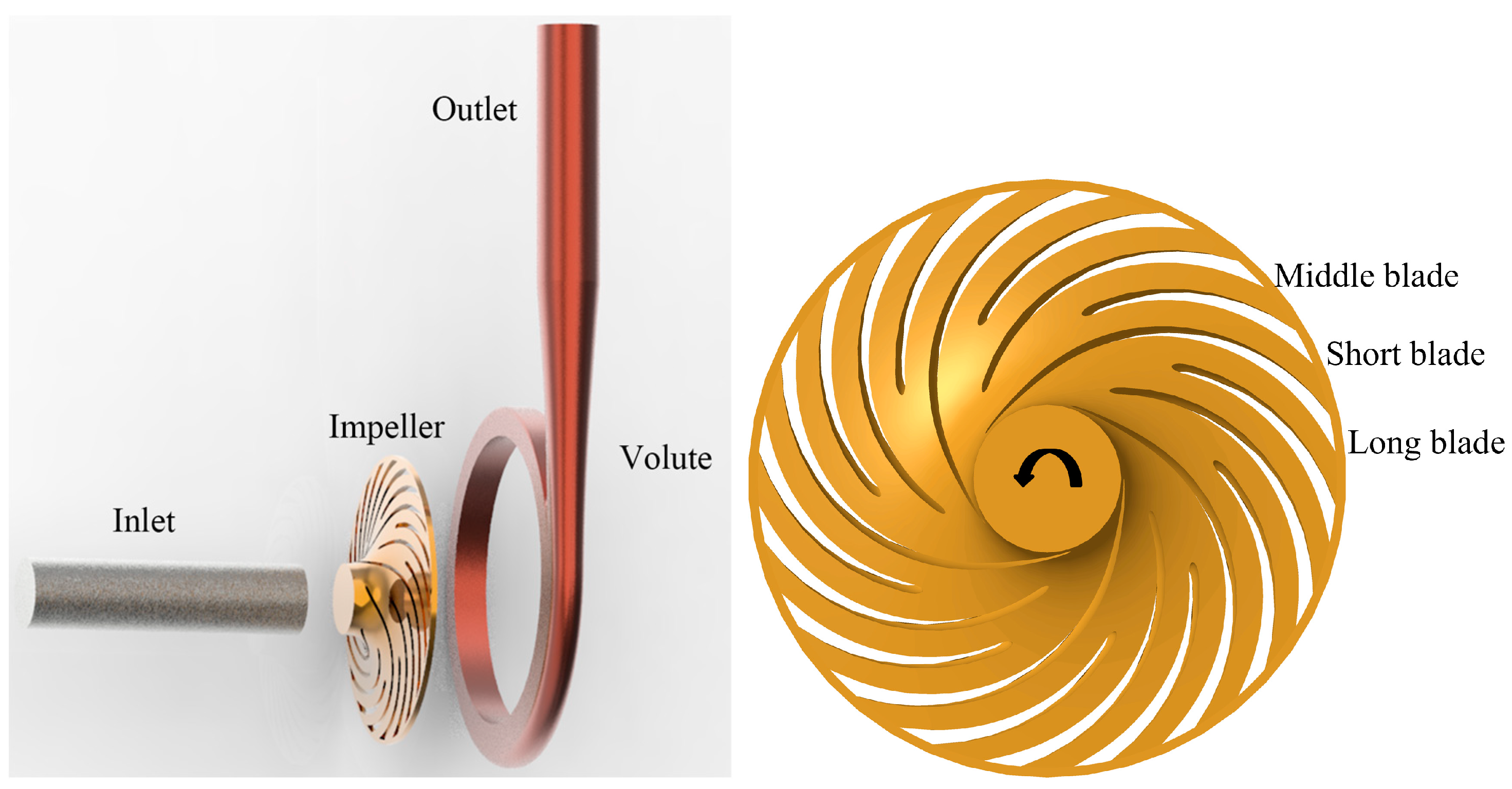
2.1. The Ultra-High-Speed Centrifugal Pump for Investigation

In this paper, to reveal the complex pressure pulsation and flow field of an ultra-high-speed centrifugal pump, we designed a model pump with 20 blades. Some design parameters of the ultra-high-speed pump are listed in Table 1. As for the model pump, to obtain its high performance, the common splitter blade was used to design the impeller, which is often applied in the pump with a low-specific speed. For the current impeller, three-layer blades were adopted, as follows: the long blade, the middle blade, and the short blade. The proposed blade structure is beneficial for improving the pump performance at low-flow rates. Usually, separation bubbles within the blade channel leads to significant losses, and by using the splitter blade, the flow separation can be suppressed to improve pump performance [5]. Finally, 20 blades were generated for the impeller, as shown in Figure 1. However, due to so many blades, the hump phenomenon (usually indicating the rotating stall phenomenon) was generated easily for the model pump, which will be discussed from pressure-pulsation and flow-distribution aspects. To predict flow structures and the resulted pressure fluctuations, the computational domain including the pump inlet, impeller, volute, and outlet is established, as presented in Figure 1.

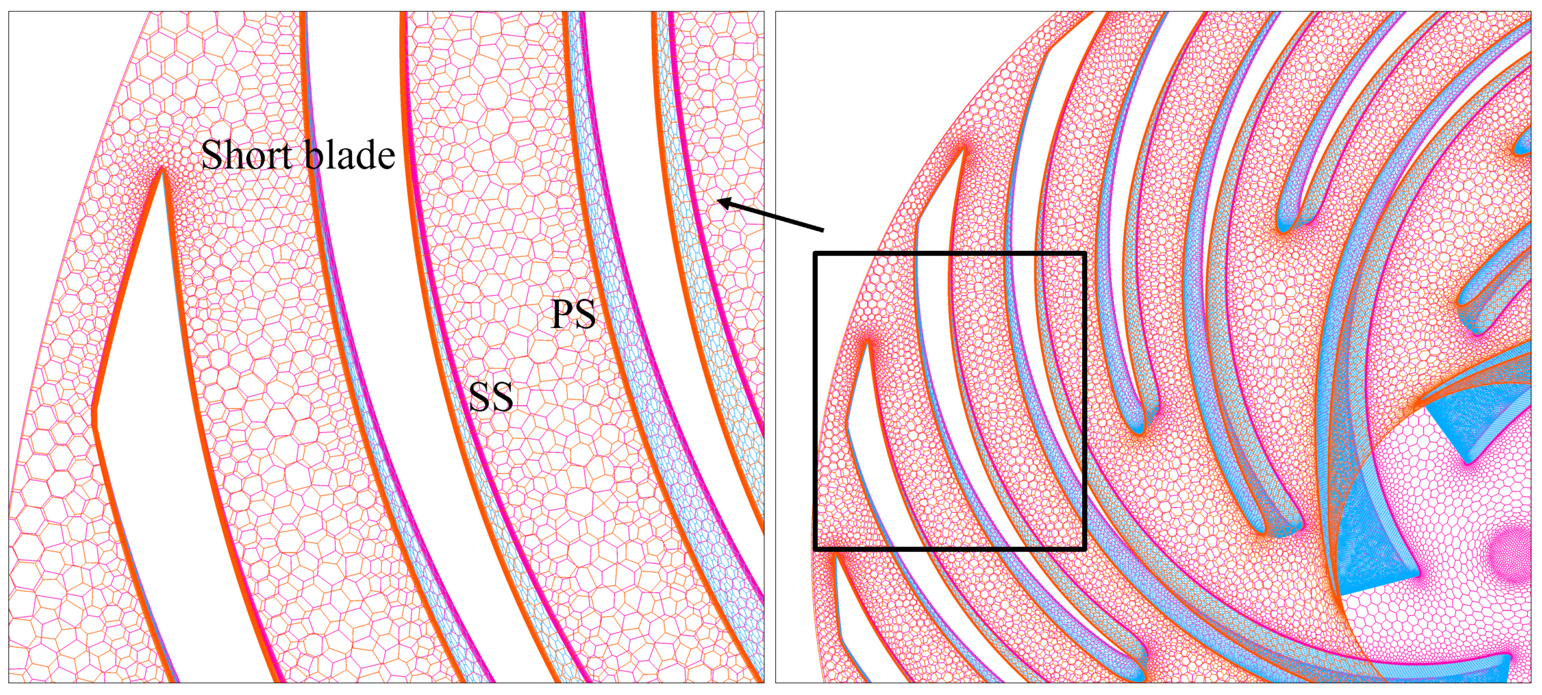
2.2. Numerical Scheme

The DDES approach is used to predict the turbulent flow within the ultra-high-speed centrifugal pump. The governing equations of DDES are listed as follows.
( ρ k ) t + ( ρ k u i ) x i = x j [ ( μ + σ k μ t ) k x j ] + P k ρ k 3 / l D D E S
( ρ ω ) t + ( ρ ω u i ) x i = x j [ ( μ + σ ω μ t ) ω x j ] + 2 ( 1 F 1 ) ρ σ ω 2 ω k x j ω x j ρ ω 2 β + ρ α μ t P k
μ t = ρ k α 1 max ( ω α 1 , S F 2 )
F1 and F2 represent SST blending functions.
The lDDES length is calculated by the following equations.
l D D E S = l R A N S f d max ( 0 , l R A N S l L E S )
l L E S = C D E S H max
l R A N S = k C μ ω
C D E S = F 1 C D E S 1 + ( 1 F 1 ) C D E S 2
Hmax represents the maximum edge length of the used grid.
Equation (8) is used to calculate the empiric blending function fd.
f d = 1 tanh [ ( C d 1 r d ) C d 2 ]
r d = ν t + v k 2 d w 2 0.5 ( S 2 + Ω 2 )
S means strain rate tensor and Ω represents the vorticity tensor.
Some constants in the formulas are given in the work [19]. In this paper, the ANSYS-Fluent code was used to conduct the simulation.
The DDES method was used to simulate complex flows in the ultra-high-speed pump, and a strict requirement of the used mesh grids was expected to be met, especially at the near wall region. During the mesh generation, the Fluent Meshing code was adopted to create the mesh grids using the Poly-Hexcore technique. Based on the blade curvature, the scoped sizing functionality was adopted to generate the surface zone scales [20]. Moreover, to precisely capture the flow at the near wall area, the surface mesh of the blade was encrypted to satisfy the meet of wall treatment method. For the mesh number between about 6.2 million and 6.7 million, the corresponding pump head changed to lower than 0.5%. This means that the pump performance was only slightly affected by further increasing the mesh number. Finally, a total mesh cell number of about 6.2 million was used for the current model pump after the mesh independent check. Figure 2 presents the Poly-Hexcore grids of the investigated impeller.
As for the DDES method, the wall treatment method was combined to resolve the complex flows at the near-wall region in order to reduce the mesh number during simulation. Figure 3 shows the y+ value on the impeller blade, and it was found that the mean value reached y+ = 5. As for the DDES approach, to simulate the turbulent flow around the near area, the y+ = 1 was better to be satisfied. However, if y+ = 1 was guaranteed, the boundary layer was expected to be further refined, which would then lead to the larger number mesh grid and more calculation resources. It is not easy to reach convergence due to the unaccepted large aspect ratio with the further refined grids on the surface. From the published works, it has been proven that by using the Poly-Hexcore grids, the main flow patterns and transient pressure signals can be obtained [20].
Generally, the DDES method can precisely predict the complex flow within the ultra-high-speed centrifugal pump due its fewer calculation resources, especially when compared to the LES method. Recently, this has attracted research attention and has been used in the published work [10]. For steady calculation via the commonly used SST k-ω model, the relative motion between the high-speed impeller and the volute was solved using the moving reference frame method. During simulation, the inlet duct was extended to generate the steady inlet flow distribution, and the velocity magnitude was selected as the inlet boundary. Meanwhile, by changing the velocity magnitude, the internal flow structures at different flow rates were predicted. For the extended outlet duct, the constant pressure was disposed as the outlet boundary. During numerical simulation, the solid surface was considered as the non-slip wall, which is widely used in the fluid machinery. Additionally, the coupling between the high-speed impeller and other domain was solved using the interface approach. The second order upwind and least square cell methods were applied for discretization. The classical SIMPLE approach was applied to couple the velocity and pressure.
When the steady calculation was finished, the results were set as the initial flow field for the unsteady simulation using the DDES method. The time-step value is vital to the resolution of pressure pulsations and flow structures; usually, the smaller the time step, the more precise flow structures can be obtained. Generally, the time step corresponds to the selected rotating degree of the impeller, which is commonly used in many published papers [12]. In the current paper, the time step Δt = 2.976 × 10⁻⁶ s was used, and the flow field was calculated when the impeller rotated by a half degree. It is believed that the precise pressure pulsations and flow structures can be resolved by the small-time step. Different from the steady simulation, the general mesh motion method was applied to treat the relative moving among different domains generated by the ultra-high-speed impeller. This means that the entire computational impeller domain rotated with a constant speed while remaining stationary at the steady calculation. For the transient simulation, 30 impeller rotations are calculated to achieve the periodic state.
During calculation, to capture pressure pulsations at different flow rates, 20 monitoring points at the front wall of the stationary volute domain were selected to obtain pressure pulsation signals. For the monitoring point D1 around the volute tongue, the angle was defined as θ = 0°. Along the clockwise direction, the angle increased 18° for every monitoring point, as shown in Figure 4. To capture pressure signals within the blade channel, one-point F1 locating between the middle and short blade channel was used to extract pressure signals under various flow rates.

3. Results and Discussions

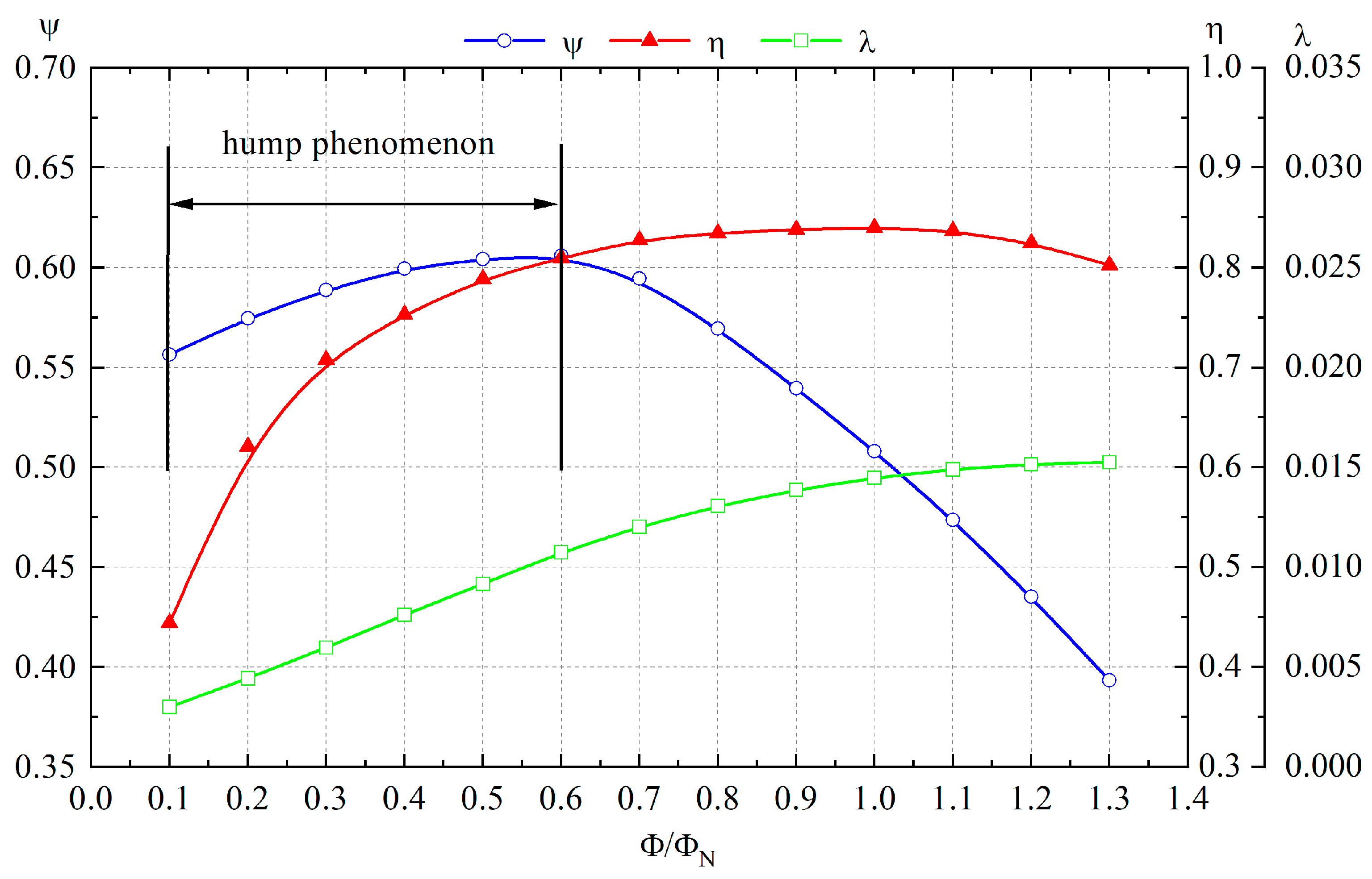
3.1. Global Performance of the Ultra-High-Speed Centrifugal Pump

The dimensionless performance parameters were obtained by the listed equations [21].
Φ N = Q d u 2 R 2 2
Ψ N = g H d u 2 2
λ N = P d ρ u 2 3 R 2 2
In Equation (10), ρ represents the water density; the value is 1000 kg/m3.
By using the steady calculation, Figure 5 presents the global performance of the ultra-high-speed centrifugal pump. From the figure, it can be seen that the pump efficiency curve maintained the highest value just at the design flow rate. This proves that the impeller and volute match very well. The highest hydraulic efficiency reached up to 83.5%. Moreover, it was found that the performance curve had a wide high-efficiency range, and from 0.6ΦN to 1.3ΦN, the efficiency curve was very flat, with an efficiency drop lower than 3%. Such changing characteristics were associated with the 20 blades applied for the typical ultra-high-speed impeller, which was also validated in other research for the centrifugal pump with a low-specific speed [7]. From the shaft power curve, it was clear that the shaft power increased at high working conditions. As for the general centrifugal pump with a low-specific speed, due to the large blade number adopted during impeller design, the hump phenomenon was easily generated, which was also observed in the ultra-high-speed centrifugal pump [6]. From the pump head curve, we found that the pump head increased within shut-off to 0.6ΦN working condition. After the point, the pump head exhibited a decreasing trend. Usually, this indicates that the unsteady rotating stall phenomenon will be generated within the impeller, which may threaten the normal operation of the pump. In this research, to reveal the influence of the rotating stall phenomenon on transient pressure pulsations and the complex flow patterns, three working conditions were investigated in detail, including 0.1ΦN, 0.2ΦN, and 1.0ΦN. For comparison, the corresponding effect will be revealed.

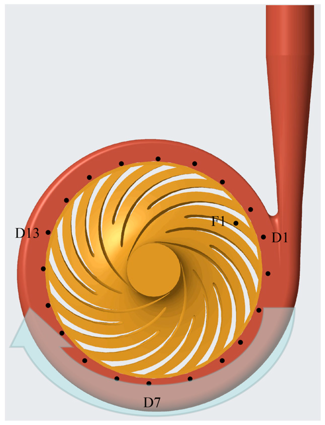
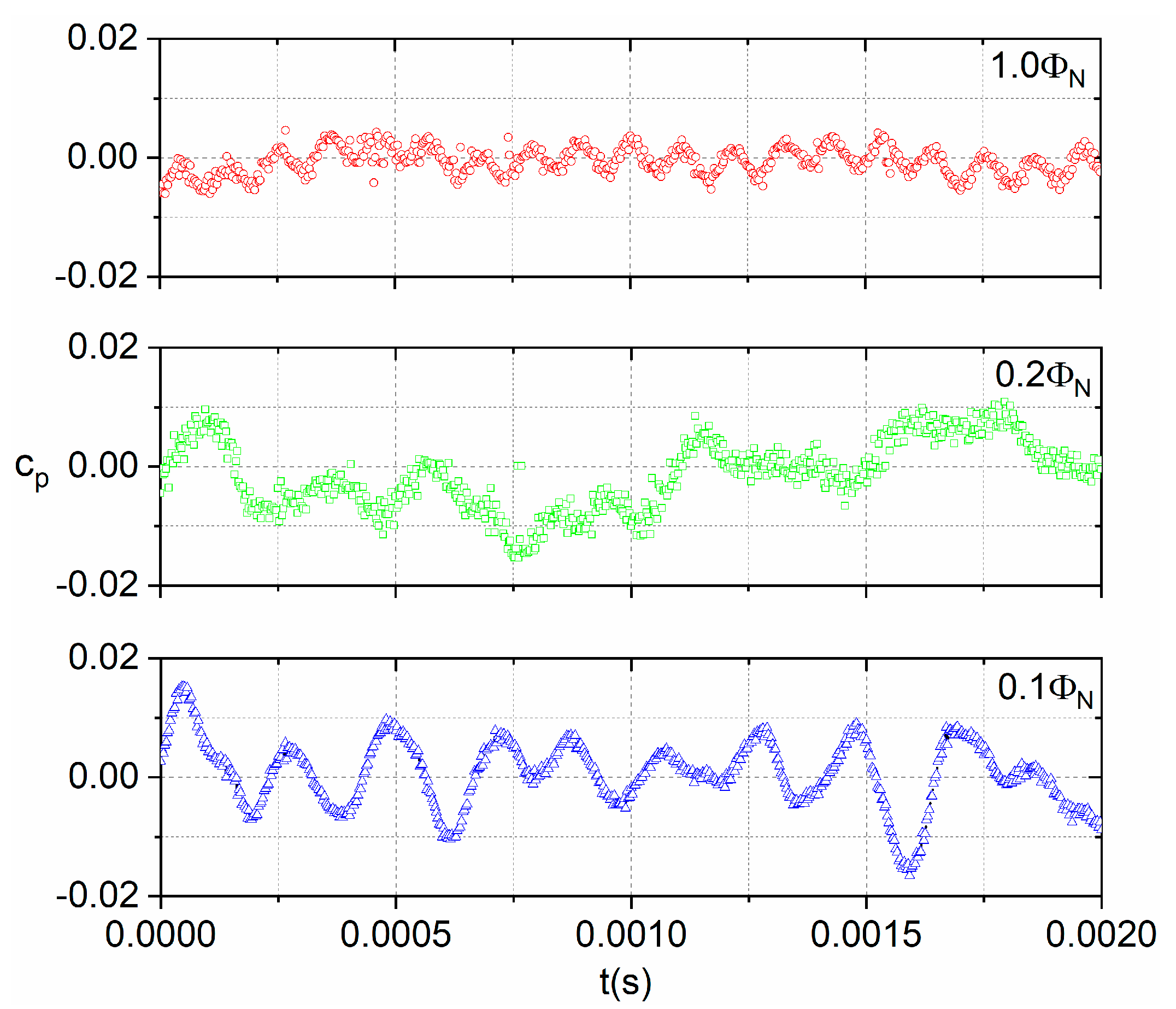
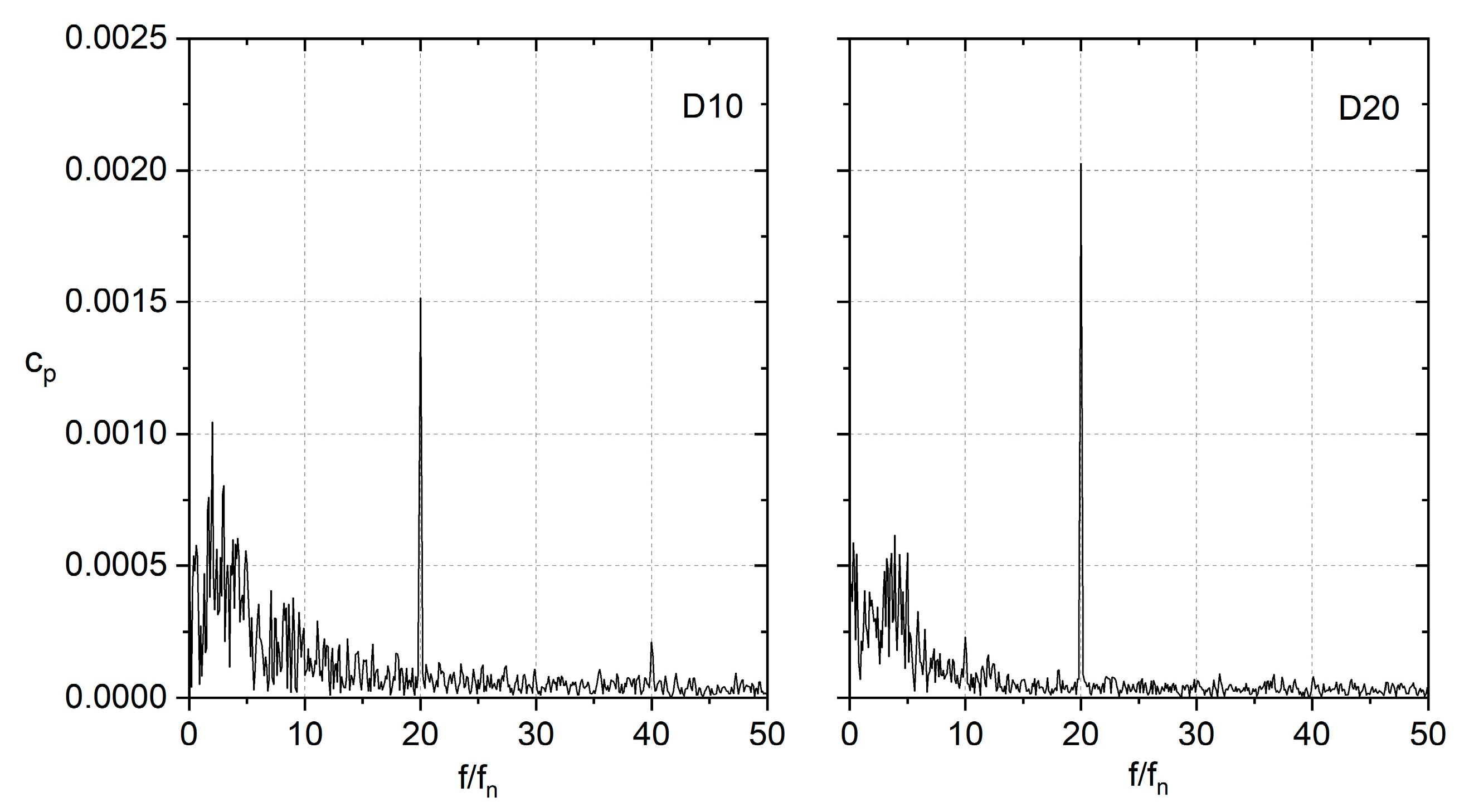
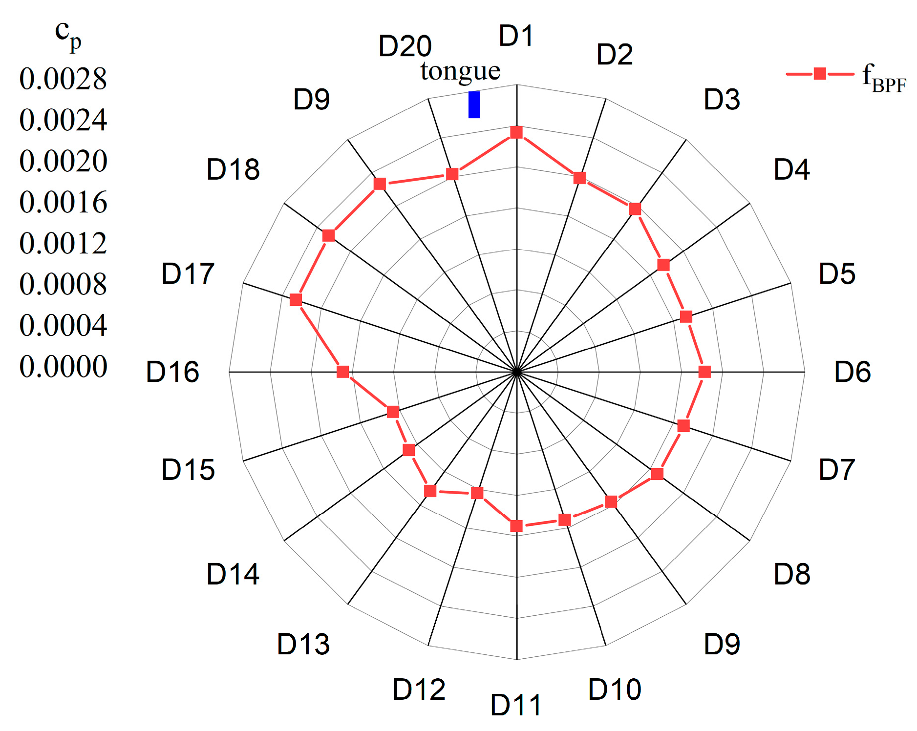
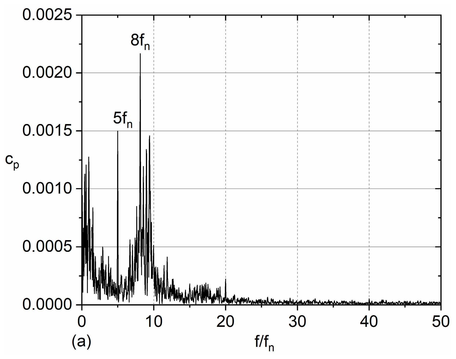
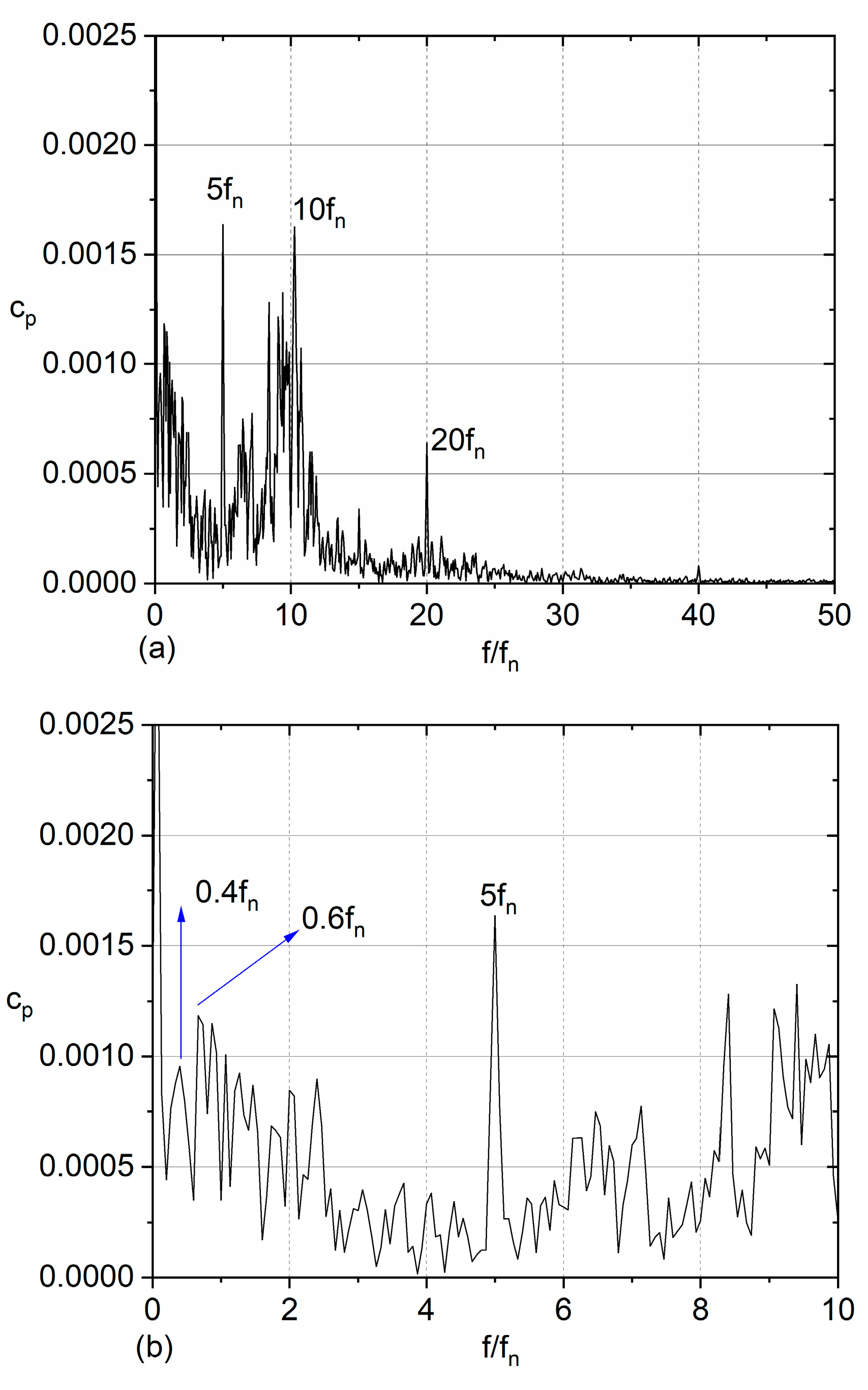
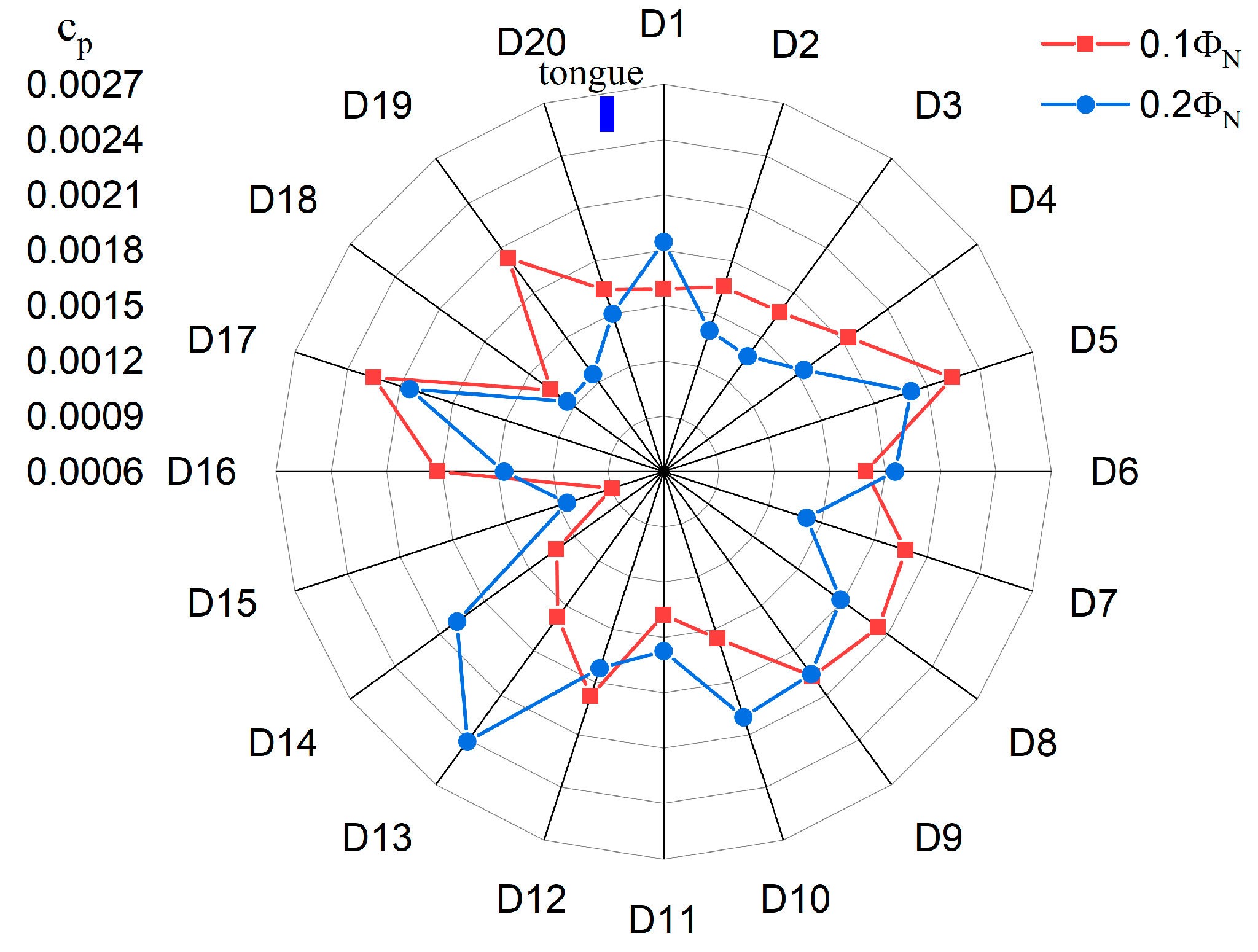
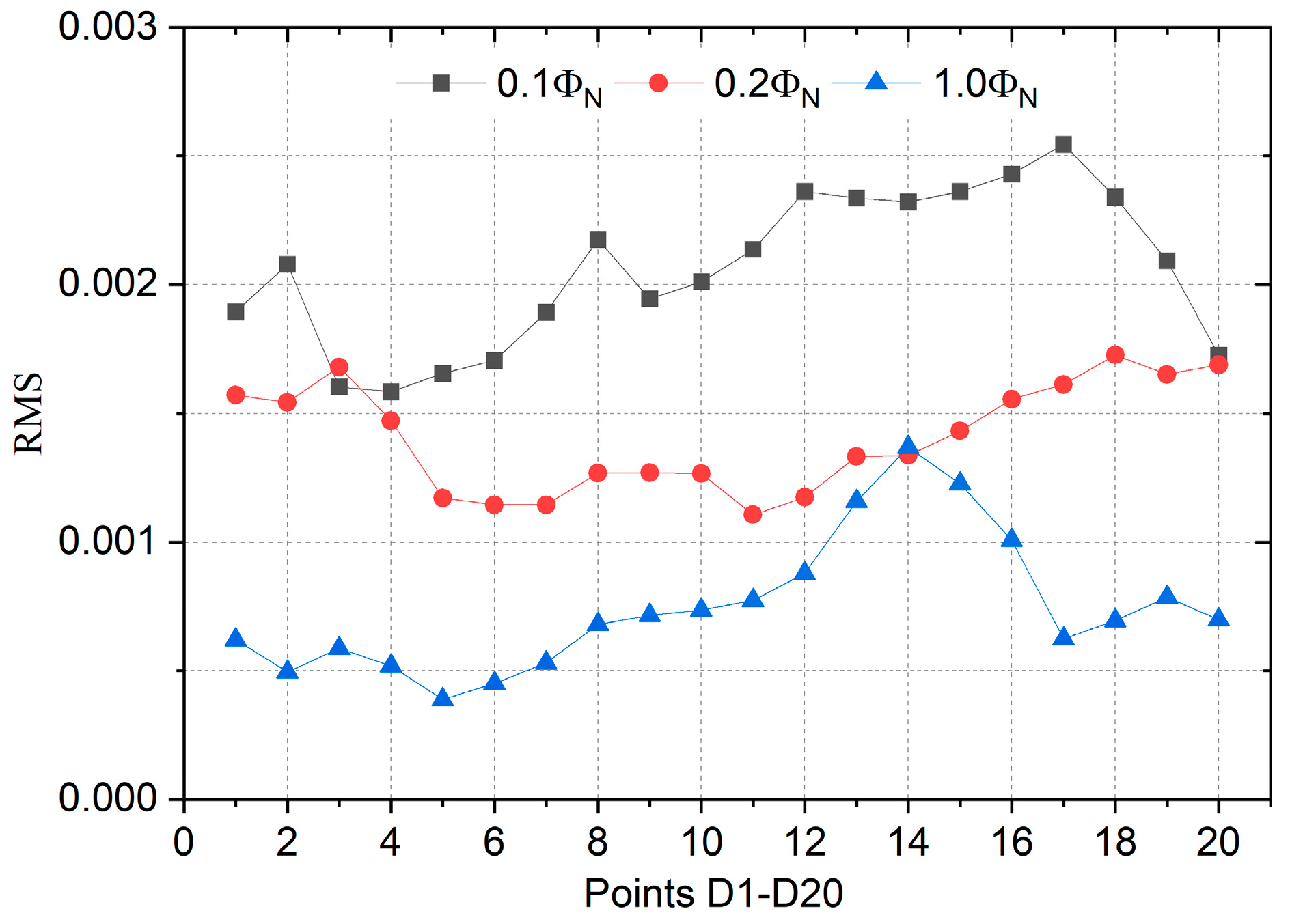
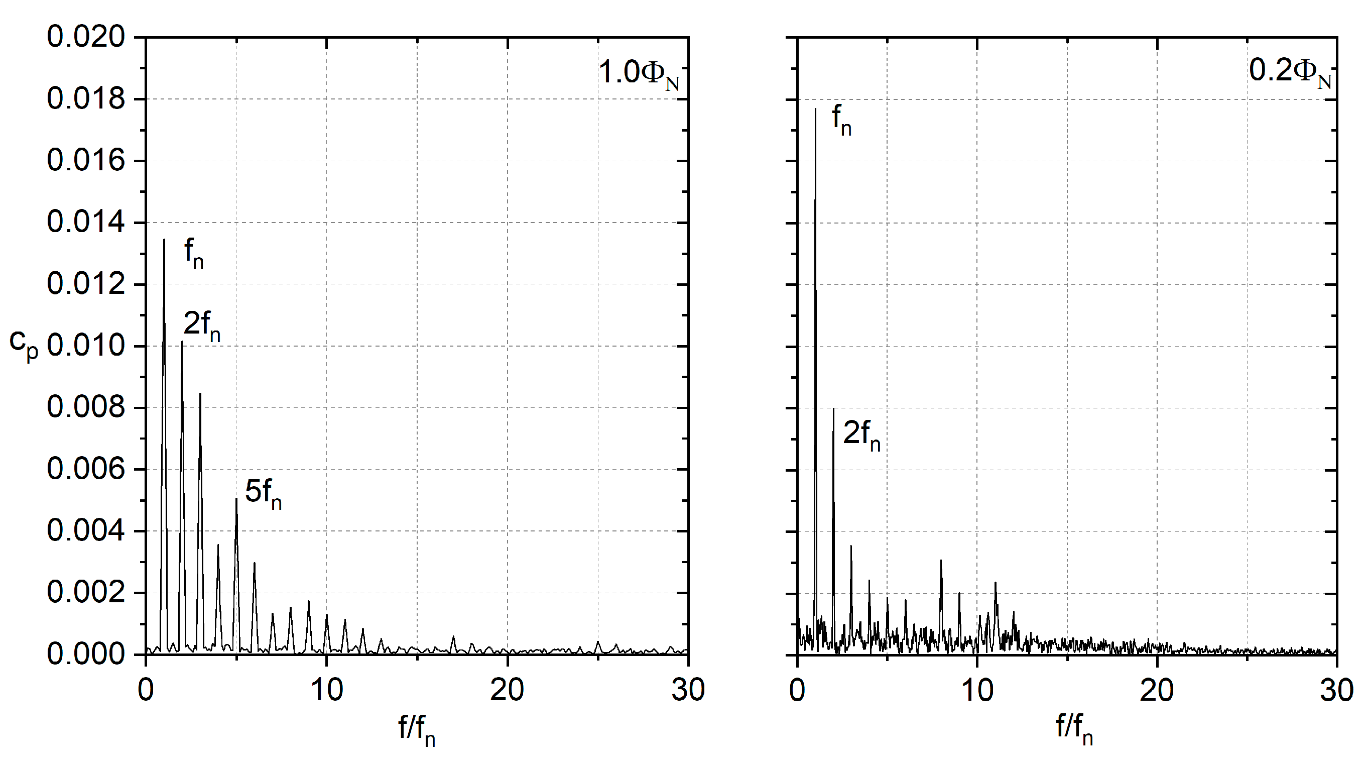
3.2. Unsteady Pressure Pulsations at Various Flow Rates

Equation (13) is used to obtain the pressure coefficient. Parameter A indicates the pressure amplitude at each monitoring point.
c p = A 0.5 ρ u 2 2
For the centrifugal pump with ultra-high speed, the rotating cycle of the impeller is T = 2.14 × 10⁻³ s. To study transient pressure pulsation characteristics, Figure 6 presents pressure pulsation signals within about one impeller rotating cycle when the model pump operates at the concerned three working conditions. It was very evident that pressure pulsation signals at different flow rates showed significant discrepancy, especially for the pump under rotating stall conditions. From pressure signals at 1.0ΦN, we found that pressure signals exhibited a pseudo-periodicity characteristic, and typical valleys and peaks with high amplitude were induced with the impeller rotating. Such a phenomenon was dominated and induced by the RSI effect, which is discussed in the published research [22]. Moreover, due to the RSI effect, within one impeller rotating cycle, 20 peaks were generated in pressure signals, and it was generated by the impeller blade number Zr = 20. From the results at 0.2ΦN and 0.1ΦN, along with the flow rate decreasing, the pressure pulsation was deeply affected at complex rotating stall conditions. At 0.1ΦN, the pressure amplitude reached about cp = 0.01. The increment was about 100% compared with the 1.0ΦN and the cp = 0.0045. This means that at low working conditions, higher pressure pulsations were induced when compared to the rated flow rate. At 0.1ΦN, within about one rotating cycle, only nine peaks were generated, which was about half of the rated flow rate. The occurrence of stall was especially revealed by the onset of lower frequencies that modulate the signals of pressure at flow rates lower than the design value. This was a very interesting phenomenon, and in the previous published works, due to the RSI effect, even at low-flow rates, the peak number also corresponded to the blade number [23]. However, from Figure 6, it is shown that for the impeller with three-layer blades, not all the blades kept the identical role for the RSI induced pressure pulsations when the ultra-high-speed pump worked at the extremely rotating stall condition. Therefore, further investigation from the spectrum and flow field aspects should be conducted to clarify the phenomenon.
To illustrate the pressure spectrum of the ultra-high-speed model pump, the FFT (fast Fourier transform) approach was adopted to obtain the spectrum characteristics. Figure 7 shows pressure spectra at points D10 and D20 when the pump operated at the rated working condition. It is generally accepted that the blade passing frequency fBPF is the main discrete component in the pressure spectrum and the corresponding amplitude can reach the maximum due to the RSI effect [23]. From Figure 7, it is shown that the complex pressure spectrum was characterized by significant peak locating at f = 20fn, which is also known as the fBPF caused by the 20 blades. As for frequencies lower than f = 10fn in the pressure spectrum, some broadband signals could also be captured, which is usually caused by the unsteady flow within the pump due to RSI phenomenon. The resulting amplitude was lower than the blade passing frequency, especially for point D20. For comparison between point D10 and D20, amplitudes at fBPF were not identical and showed evident differences. At point D20, the corresponding amplitude was about 137% of that at point D10. This indicates that pressure pulsations at the points around the blade exit were not the same, which was similar with the centrifugal pump with a commonly low speed [23].
For the unsteady simulation, 20 monitoring points were applied to capture pressure pulsation signals around the blade exit. Usually, it is accepted that flow field is not uniform around the impeller outlet, which leads to the difference of pressure pulsations at different points. To reveal pressure pulsation amplitudes at fBPF of all the calculated 20 points, Figure 8 presents the distribution of the pressure amplitude when the high-speed pump operates under the rated working condition. As observed from Figure 8, the distribution of pressure amplitude at fBPF has an evident difference from comparison with the normal-speed centrifugal pump, e.g., rotating speed n = 1450 r/min [13]. Usually, for the normal-speed centrifugal pump, peaks and valleys can also be generated for the pressure-amplitude distribution around the blade exit due to the RSI effect as validated by numerical and experimental results [23,24]. However, for the current high-speed centrifugal pump, no significant peaks and valleys were observed (Figure 8). This means that by using 20 blades, flow uniformity around the blade exit was improved, and the RSI effect between different points was not very significant. Finally, pressure amplitudes of some points were approximately equivalent, as seen at points D2–D8, and the amplitudes were between cp = 0.0016–0.002, which was quite different from the normal-speed centrifugal pump. For comparison, it was also found that for points D17–D20 at the left region of the tongue (the blue rectangle), pressure pulsation amplitudes were much larger than points D2–D16. This proves that due to the impeller sweeping, the volute and intense pressure pulsations were generated at the volute tongue downstream, which was consistent with the normal low-speed centrifugal pump [24,25].
To reveal the influence of the rotating stall phenomenon on transient pressure pulsations, the pressure spectrum at 0.2ΦN was investigated. Figure 9a shows the pressure spectrum of point D20. Usually, the rotating stall excites the low-frequency component, so to obtain the stalled frequency, Figure 9b also shows the corresponding pressure spectrum characteristic in the frequency band f = 0–10 fn. In Figure 9a, within the hump phenomenon region, it is shown that the pressure spectrum was obviously affected at 0.2ΦN. We found that the component at fBPF almost could not be captured, and the amplitude was remarkably reduced when compared with the rated flow rate. Meanwhile, the peak at fBPF no longer dominated the pressure spectrum. At f = 8fn, the highest-pressure amplitude was generated, and it was the leading frequency at 0.2ΦN. We could still capture the component at 5fn, and the amplitude was about 70% of 8 fn. From Figure 9a, it is shown that a pressure spectrum at a low working condition of the current ultra-high-speed pump was different from the centrifugal pump with normal speed. Usually, for the normal-speed pump, even at a low-flow rate, the fBPF is still the leading frequency in the pressure spectrum, as proven in past works [13,17]. However, such a principle changed for the current pump. We inferred that such phenomenon was caused by the typical flow structure in the blade channels at the stalled working condition. Generally, at a rotating stall status, an evident separation bubble with large scales is generated in some blade channels of the impeller. Partial channels may even be blocked by the separation bubble. Then, the flow rate will decrease nearly to zero. In that case, no fluid or little fluid will discharge from the blade channel, and the RSI effect between the blade channel where the stall occurs, and the tongue will be dramatically modified. This was the reason that, in this study, the component at fBPF was not the leading frequency in the pressure spectrum, and the dominant component deviated to 8 fn. As for the peak at 5 fn, a similar reason can be given. If we focus on the flow filed between the two long blades, not every blade channel between short and middle blades stalled; some fluid still discharged between the two adjacent long blades, leading to the interaction with tongue. Five long blades were used for the impeller, so f = 5 fn was excited. Flow field distribution will be discussed in the following contents to support the deduction.
In Figure 9b, by focusing on the frequency lower than fn, it is shown that several discrete components were generated in the pressure spectrum as a result of the rotating stall phenomenon. Generally, the rotating stall induces the component with a frequency f < fn. In Figure 9b, it is shown that components at 0.2 fn, 0.4 fn, and 0.6 fn were captured, and 0.2 fn was considered as the fundamental frequency. Components at 0.4 fn and 0.6 fn were the higher harmonic of 0.2 fn. Finally, we found that for the current investigated ultra-high-speed centrifugal pump, the resulted rotating stall frequency at 0.2ΦN appeared at 0.2 fn.
To further analyze the pressure pulsation at an extremely low working condition (0.1ΦN), Figure 10 shows the pressure spectrum at point D20. The pressure spectrum was similar with that at 0.2ΦN. From Figure 10a, it is observed that the component at 5 fn reached the maximum, and its amplitude was much larger than the peak at 20 fn. Around 10 fn, the significant peak was also generated in the pressure spectrum. From Figure 10b, when looking at the low frequency, it can be seen that the components at 0.4 fn and 0.6 fn were captured in the pressure spectrum. Combined with the result in Figure 9b, we can infer that the component at 0.2fn was the rotating stall frequency, and 0.4 fn and 0.6 fn were the high harmonics. Finally, the rotating stall frequencies at various conditions went unchanged for the ultra-high speed centrifugal pump, which was identical with the published work for a centrifugal pump with normal rotating speed [17].
From Figure 9 and Figure 10, it can be seen that the components at 5fn were both captured in the pressure spectrum, and the corresponding amplitude almost reached its maximum. To investigate amplitudes at 5fn for all 20 points, Figure 11 shows the distribution of the pressure amplitude at 5fn along the blade exit when the pump operated at 0.1ΦN and 0.2ΦN. For comparison, it was proved that the effect of the working condition on the pressure pulsation amplitude was not consistent for the point along the impeller exit. At 0.1ΦN, the pressure pulsation amplitudes at some points were larger when compared with 0.2ΦN, while the opposite rule was found at point D13. At 0.1ΦN and 0.2ΦN, the average pressure amplitudes for all 20 points were cp = 0.00172 and cp = 0.00168, and the difference was about 2.5%. This means that the pressure pulsation energy at 5fn was only slightly affected by the working condition when focused on the average pressure amplitude.
From Figure 9 and Figure 10, it is evident that at the rotating stall condition components in the low frequency band f < fn were obviously affected. To quantitatively evaluate the influence of the working condition on the low frequency components, the RMS approach was adopted to calculate the total pressure pulsation energy of all frequencies, which is defined in Equation (14) [17].
R M S = 1.63 ρ u 2 2 1 2 ( 1 2 A 0 2 + i = 2 n A i 1 2 + 1 2 A n 2 )
where Ai is the pressure pulsation amplitude at every frequency.
Figure 12 shows RMS values of the 20 monitoring points under three flow rates: 0.1ΦN, 0.2ΦN, and 1.0ΦN. When comparing different flow rates at the rotating stall condition, the low frequency band signals were significantly affected, and the RMS value was rapidly increased. As seen at 0.2ΦN, except for point D14, the RMS values at the other points were obviously larger than the rated working condition. The average increment reached about 90% from 1.0ΦN to 0.2ΦN. For the ultra-high-speed pump under 0.1ΦN, the RMS value increased significantly, and the average increment was about 45% from 0.2ΦN to 0.1ΦN. For RMS comparison, due to the occurrence of the rotating stall phenomenon, some discrete peaks with low frequency were generated in the pressure spectrum with high amplitude at low-flow rates.
During the calculation, a monitoring point F1 was also placed in the blade channel to capture pressure pulsation signals under various flow rates. Figure 13 presents pressure spectra at point F1 under 0.2ΦN and 1.0ΦN. At the rated working condition, it was observed that the component at the shaft rotating frequency dominated the pressure spectrum. its high harmonics—2fn, 3fn, 4fn, 5fn, etc.—could also be captured. For a frequency larger than 10fn, the pressure amplitude was dramatically reduced. The pressure spectrum at F1 was different from the point at the impeller exit, and the component at fBPF was the dominant frequency. At the complex rotating stall condition 0.2ΦN, the pressure spectrum showed a similarity with the rated flow rate, and the pressure amplitude at the shaft rotating frequency fn also reached the maximum. The corresponding high harmonics could also be identified. However, the amplitude was rapidly reduced when compared with the rated working condition. This means that the pressure pulsation energy further concentrated at fn at the rotating stall condition, and the increment was about 30% from comparison with 1.0ΦN.

3.3. Complex Flow Structures within the Impeller

Generally, at low-flow rates, the internal flow structures are affected, leading to typical pressure spectrum characteristics for pumps operating at low-flow rates. To reveal complex flow distributions in the impeller at rotating stall conditions, Figure 14 presents the relative velocity distributions within the impeller channels at three flow rates. The blue rectangle represents the volute tongue position. At the rated operating condition, the uniform and perfect flow field was developed inside the blade channels, and the flow separation did not occur. The fluid discharged from the blade channels smoothly, and the relative velocity increased towards the impeller outlet. At the reduced flow rate 0.2ΦN, the flow distribution exhibited an evident difference with the rated operating condition. The relative velocity magnitude was obviously reduced. In some blade channels, large-scale flow separation was generated, especially for the blade channels around the volute tongue position. It was found that at this typical region, the fluid velocity nearly reached zero, which indicates that the blade channel was almost blocked by the large-scale separation bubble, losing the flow capacity. In some blade channels, the flow structure was only a little affected when the blade channels were at a lower region of the impeller. No separation bubble was generated, and the flow passed the blade channel smoothly. Such a typical flow distribution characteristic has often been observed when the centrifugal pump operates under the stalled condition [18]. Caused by the evolution and transfer of the stall cell in different blade channels, partial blade channels were blocked in such instances, while others were not. For the pump under 0.1ΦN, the flow distribution was found to be similar with 0.2ΦN. The blade channels around the tongue were totally occupied by the large-scale flow separation bubble, indicating that the blade channels were stalled.
To obtain the evolution characteristic of the flow structure, Figure 15 presents relative velocity distributions at six moments with the impeller rotating at 0.1ΦN. At an initial moment, t = t0, the blade B1 faced the volute tongue, and the corresponding blade channels were characterized and blocked by the separation bubble. This indicates that the corresponding blade channels were in a stalled condition and losing flow capacity. At moment t0 + 1/6T, the blade B1 moved to the downstream region of the tongue, and the large-scale separation bubble disappeared. The two blade channels close to the blade B1 recovered from the stalled status, and the blade channels reattained the flow capacity, as characterized by the large relative velocity magnitude. At this moment, the blade B5 moved towards the volute tongue, and it was observed that for the blade channels close to blade B5, a significant flow separation was generated. For the impeller at moments t0 + 3/6T and t0 + 4/6T, the blade channels close to blade B1 were not blocked. At t0 + 5/6T, with the blade B1 moving close to the tongue again, evident flow separation bubbles were developed, which proved that the flow status deteriorated again. Using unsteady flow evolution analysis, it was concluded that for the blade channels approaching close to the tongue, flow distribution deteriorated, leading to separation bubbles, which block the blade channels and thus result in a stalled condition. Meanwhile, for the blade moving far from the tongue region, the stalled impeller channels relieved and recovered flow capacity. The volute tongue acted as the trigger to generate the separation bubble, leading to the stalled status. Such an effect was also validated in the published research of the centrifugal pump with a normal rotating speed [17].

4. Conclusions

In this paper, complex pressure pulsations excited by the unsteady flow of an ultra-high-speed centrifugal pump was investigated via the numerical method, and the DDES scheme was adopted to calculate the unsteady flow. Three working conditions were mainly focused to clarify pressure pulsation and velocity distribution characteristics. The following conclusion were obtained.
At the rated flow rate, the component at fBPF was captured at every monitoring point with the highest amplitude caused by the RSI effect. The component at 5fn reached the maximum in pressure spectrum under the rotating stall status, which was different from the published results for the low-speed centrifugal pump. Meanwhile, the pressure amplitude distribution at fBPF around the impeller exit was not characterized by the evident peak and valley, which meant that due to the three-layer blades, the flow uniformity around the blade exit improved significantly.
At the rotating stall status, evident components in the low frequency band were captured, and the peaks at 0.2 fn were the rotating stall-induced frequency at 0.1ΦN and 0.2ΦN. The rotating stall frequency went unchanged at the concerned flow rates. At the stalled condition, pressure pulsation energy in the low frequency band increased rapidly.
For the concerned monitoring point within the blade channel, the shaft rotating frequency was the dominant component at the rated and rotating stall conditions. At a low-flow rate, the pressure pulsation amplitude at the shaft rotating frequency increased compared with the rated working condition.
For comparison with the rated working, some blade channels were almost blocked by large separation bubbles, leading to the blade channels losing their flow capacity at the stalled condition, especially blade channels around the tongue region. When the blade passed the tongue, the blade channels were periodically characterized by the flow separation. This means that the tongue induced and triggered the stalled status for the blade sweeping the tongue.

Author Contributions

Investigation, D.L. and J.C.; writing—original draft, Z.Z.; writing—review and editing, N.Z.; supervision, H.L. All authors have read and agreed to the published version of the manuscript.

Funding

This work is funded by the National Science and Technology Major Project (Project No. J2019-V-0016-0111) and the Research Foundation of Excellent Young Teachers of Jiangsu University.

Data Availability Statement

Not available.

Conflicts of Interest

The authors declare no conflict of interest.

Nomenclature

QdFlow capacity, m3/h
HdPump head, m
PdRated shaft power, W
ndShaft speed, r/min
nsPump-specific speed
ΦNFlow capacity coefficient
ΨNHead coefficient
λNPower coefficient
ZrTotal blade number of the impeller
ηEfficiency
D1Suction diameter, mm
D2Impeller outlet diameter, mm
D4Volute outlet diameter, mm
ϕWrap angle, °
u2Tangential speed at the impeller outlet, m/s
β2Blade outlet angle, °
ρWater density, m3/h
fnShaft rotating frequency, Hz
fBPFBlade passing frequency, Hz
RSIRotor-stator interaction
tTime, s
ΔtTime step, s
APressure pulsation amplitude, Pa
y+Value of y plus
cpPressure coefficient
RMSRoot mean square

References

  1. Weijun, W.; Tailong, L.I. Optimum design of centrifugal aviation fuel pump based on splitter blades technology. Eng. J. Wuhan Univ. 2021, 54, 557–562. [Google Scholar]
  2. Li, D.; Ren, Z.; Li, Y.; Miao, B.; Gong, R.; Wang, H. Thermodynamic Effects on Pressure Fluctuations of a Liquid Oxygen Turbopump. J. Fluids Eng. Trans. ASME 2021, 143, 111401. [Google Scholar] [CrossRef]
  3. Posa, A.; Lippolis, A. A LES investigation of off-design performance of a centrifugal pump with variable-geometry diffuser. Int. J. Heat Fluid Flow 2018, 70, 299–314. [Google Scholar] [CrossRef]
  4. Posa, A. LES investigation on the dependence of the flow through a centrifugal pump on the diffuser geometry. Int. J. Heat Fluid Flow 2021, 87, 108750. [Google Scholar] [CrossRef]
  5. Yuan, Y.; Yuan, S. Analyzing the effects of splitter blade on the performance characteristics for a high-speed centrifugal pump. Adv. Mech. Eng. 2017, 9, 1–11. [Google Scholar] [CrossRef]
  6. Zhang, J.; Yang, H.; Liu, H.; Xu, L.; Lv, Y. Pressure Fluctuation Characteristics of High-Speed Centrifugal. Processes 2021, 9, 2261. [Google Scholar] [CrossRef]
  7. Guo, X.; Jiang, C.; Qian, H.; Zhu, Z. The Influence of Tip Clearance on the Performance of a High-Speed Inducer Centrifugal Pump under Different Flow Rates Conditions. Processes 2023, 11, 239. [Google Scholar] [CrossRef]
  8. Chao, W.X.; Shi, B.L.; Ruan, H.; Dong, W. The Cavitation Characteristics of High Speed Centrifugal Pumps with Different Impeller Types. Front. Energy Res. 2022, 10, 811690. [Google Scholar] [CrossRef]
  9. Zhang, N.; Li, D.; Jiang, J.; Gao, B.; Ni, D.; Alubokin, A.A. Experimental Investigation on Velocity Fluctuation in a Vaned Diffuser Centrifugal Pump Measured by Laser Doppler Anemometry. Phys. Fluids 2023, 32, 125108. [Google Scholar] [CrossRef]
  10. Zhang, N.; Jiang, J.; Gao, B.; Liu, X. DDES analysis of unsteady flow evolution and pressure pulsation at off-design condition of a centrifugal pump. Renew. Energy 2020, 153, 193–204. [Google Scholar] [CrossRef]
  11. Zhang, N.; Liu, X.; Gao, B.; Wang, X.; Xia, B. Effects of modifying the blade trailing edge profile on unsteady pressure pulsations and flow structures in a centrifugal pump. Int. J. Heat Fluid Flow 2019, 75, 227–238. [Google Scholar] [CrossRef]
  12. Ni, D.; Zhang, N.; Gao, B.; Li, Z.; Yang, M. Dynamic measurements on unsteady pressure pulsations and flow distributions in a nuclear reactor coolant pump. Energy 2020, 198, 117305. [Google Scholar] [CrossRef]
  13. Barrio, R.; Parrondo, J.; Blanco, E. Numerical analysis of the unsteady flow in the near-tongue region in a volute-type centrifugal pump for different operating points. Comput. Fluids 2010, 39, 859–870. [Google Scholar] [CrossRef]
  14. Keller, J.; Blanco, E.; Barrio, R.; Parrondo, J. PIV measurements of the unsteady flow structures in a volute centrifugal pump at a high flow rate. Exp. Fluids 2014, 55, 1820. [Google Scholar] [CrossRef]
  15. Feng, J.; Ge, Z.; Yang, H.; Zhu, G.; Li, C.; Luo, X. Rotating stall characteristics in the vaned diffuser of a centrifugal pump. Ocean Eng. 2021, 229, 108955. [Google Scholar] [CrossRef]
  16. Ullum, U.; Wright, J.; Dayi, O.; Ecder, A.; Soulaimani, A.; Piché, R.; Kamath, H. Prediction of rotating stall within an impeller of a centrifugal pump based on spectral analysis of pressure and velocity data. J. Phys. Conf. Ser. 2006, 52, 36–45. [Google Scholar] [CrossRef]
  17. Zhang, N.; Gao, B.; Ni, D.; Liu, X. Coherence analysis to detect unsteady rotating stall phenomenon based on pressure pulsation signals of a centrifugal pump. Mech. Syst. Signal Process. 2021, 148, 107161. [Google Scholar] [CrossRef]
  18. Zhao, X.; Xiao, Y.; Wang, Z.; Luo, Y.; Cao, L. Unsteady flow and pressure pulsation characteristics analysis of rotating stall in centrifugal pumps under off-design conditions. J. Fluids Eng. Trans. ASME 2018, 140, 021105. [Google Scholar] [CrossRef]
  19. Zhang, N.; Liu, X.; Gao, B.; Xia, B. DDES analysis of the unsteady wake flow and its evolution of a centrifugal pump. Renew. Energy 2019, 141, 570–582. [Google Scholar] [CrossRef]
  20. Zore, K.; Sasanapuri, B.; Parkhi, G.; Varghese, A. Ansys mosaic poly-hexcore mesh for high-lift aircraft configuration. In Proceedings of the 21th Annual CFD Symposium, Bengaluru, India, 8–9 August 2019; pp. 1–11. [Google Scholar]
  21. Gao, B.; Zhang, N.; Li, Z.; Ni, D.; Yang, M.G. Influence of the Blade Trailing Edge Profile on the Performance and Unsteady Pressure Pulsations in a Low Specific Speed Centrifugal Pump. J. Fluids Eng. Trans. ASME 2016, 138, 051106. [Google Scholar] [CrossRef]
  22. Posa, A. LES study on the influence of the diffuser inlet angle of a centrifugal pump on pressure fluctuations. Int. J. Heat Fluid Flow 2021, 89, 108804. [Google Scholar] [CrossRef]
  23. Posa, A.; Lippolis, A. Effect of working conditions and diffuser setting angle on pressure fluctuations within a centrifugal pump. Int. J. Heat Fluid Flow 2019, 75, 44–60. [Google Scholar] [CrossRef]
  24. Zhang, N.; Li, D.; Gao, B.; Ni, D.; Li, Z. Unsteady Pressure Pulsations in Pumps—A Review. Energies 2023, 16, 150. [Google Scholar] [CrossRef]
  25. Li, D.L.; Zhang, N.; Jiang, J.X.; Gao, B.; Alubokin, A.A.; Zhou, W.J.; Shi, J.L. Numerical investigation on the unsteady vortical structure and pressure pulsations of a centrifugal pump with the vaned diffuser. Int. J. Heat Fluid Flow 2022, 98, 109050. [Google Scholar] [CrossRef]
Figure 1. Computational domain of the investigated ultra-high-speed pump.
Energies 16 04476 g001
Figure 2. Poly-Hexcore mesh of the impeller.
Energies 16 04476 g002
Figure 3. Contour of y+ distribution on the 20 blades.
Energies 16 04476 g003
Figure 4. Monitoring points to extract pressure pulsation signals.
Energies 16 04476 g004
Figure 5. Global performance of the high-speed centrifugal pump.
Energies 16 04476 g005
Figure 6. Pressure signals at point D20 at three flow rates.
Energies 16 04476 g006
Figure 7. Pressure spectra at points D10 and D20 for the model pump working at 1.0ΦN.
Energies 16 04476 g007
Figure 8. Pressure amplitudes at component fBPF of the 20 monitoring points at the impeller exit.
Energies 16 04476 g008
Figure 9. (a) Pressure spectra at monitoring point D20 for the model pump working at 0.2ΦN; (b) the corresponding spectrum within 0–10 fn.
Energies 16 04476 g009aEnergies 16 04476 g009b
Figure 10. (a) Pressure spectra at monitoring point D20 for the model pump working at 0.1ΦN; (b) the corresponding spectrum within 0–10 fn.
Energies 16 04476 g010
Figure 11. Amplitudes at 5fn of the 20 points under 0.1ΦN and 0.2ΦN.
Energies 16 04476 g011
Figure 12. RMS values within frequency band lower than fn at 0.1ΦN, 0.2ΦN, and 1.0ΦN.
Energies 16 04476 g012
Figure 13. Pressure spectra at monitoring point F1 under 1.0ΦN and 0.2ΦN.
Energies 16 04476 g013
Figure 14. Relative velocity distributions within the blade channels.
Energies 16 04476 g014
Figure 15. Transient relative velocity patterns at various moments at 0.1ΦN.
Energies 16 04476 g015
Table 1. Parameters of the investigated ultra-high-speed pump.
ParametersValue
Flow rate Qd50 m3/h
Head Hd1500 m
Rotating speed nd28,000 r/min
Specific speed n s = 3.65 n d Q d / H d 0.75 50
Total blade number Zr20
Long-blade number Zr-long5
Middle-blade number Zr-mid5
Short-blade number Zr-short10
Suction diameter D130 mm
Outlet diameter D2116 mm
Volute exit diameter D430 mm
Blade outlet angle β225°
Wrap angle ϕ130°
Tangential speed at the impeller outlet u2170 m/s
Shaft frequency fn466 Hz
Blade passing frequency fBPF9333 Hz
Disclaimer/Publisher’s Note: The statements, opinions and data contained in all publications are solely those of the individual author(s) and contributor(s) and not of MDPI and/or the editor(s). MDPI and/or the editor(s) disclaim responsibility for any injury to people or property resulting from any ideas, methods, instructions or products referred to in the content.

