Abstract
The paper presents analytical formulas for computation in the time domain of electromagnetic (EM) fields generated by tortuous cloud-to-cloud (CC) lightning channels over a perfectly conducting ground. For the first time, the study was not limited to a horizontal lightning path but was extended to take into account the natural, tortuous geometry of the lightning channel. After the calculation of the step response, a convolution integration was applied for the computation of the fields generated by an arbitrary current source. The produced electric and magnetic fields were then compared with the fields generated by a horizontal channel. The method can be of primary importance to evaluating the hazards for electric and electronic systems of flying aircraft, estimating the voltages induced on overhead transmission lines by CC lightning, and, in general, evaluating the induced effects on sensitive electric and electronic components. Moreover, it may represent a simple, robust, and time-saving tool for estimating important physical parameters that characterize lightning phenomena.
1. Introduction
Lightning is a natural, complex, and dramatic phenomenon that has long had an influence on human psychology and behaviour. The electrical nature of both thunderclouds and lightning was proven by Franklin in 1751 [1]. However, major breakthroughs in lightning research mainly came with the pioneering work of Wilson in regards to the charge structure in clouds [2] and with the invention of the strike camera by Boys in 1926 [3], which produced evidence of the leader channel propagation in cloud-to-ground (CG) lightning [4]. The interest in studies on lightning discharge then grew exponentially: in particular, the discharges occurring between clouds and ground (the so-called cloud-to-ground lightning discharges) were (and are) extensively studied due to their implications on human injuries [5,6], ignition of forest fires, and damage and heavy disturbance to energy and communication transmission lines [7,8,9] and to electric and electronic devices [10,11,12,13], among other reasons. Conversely, although the most frequent lightning phenomena (about 75 percent of the total number of events) occur inside clouds, between clouds, or between clouds and air [14,15] little data are available on cloud discharges due to the inherent difficulty in collecting them and due to the limited hazard on humans, ground objects, and systems. However, in the last two decades, greater attention to cloud discharges has resulted in increased interest due to their potential direct or indirect effects on aircraft and spacecraft [16,17], especially when, for weight reduction and fuel savings, the metallic structure of aeroplanes and avionic systems is replaced by carbon fibre-reinforced composites [18] which provide lower electromagnetic shielding [19,20]. Furthermore, recent studies have provided evidence for the indirect effects of cloud-to-cloud (CC) lightning on overhead medium voltage lines which causes line faults due to inadequate creepage distance of line insulators during wet conditions [21]. Moreover, it should be noted that information concerning the evolution of lightning phenomena, such as the indirect derivation of lightning physical parameters (i.e., the amplitude, shape, and speed of the propagating current or the charge deposition along the channel, etc.) can be obtained from the analysis of EM field waveforms [22]; thus far, the estimation of such parameters has been generally obtained by analysing vertical cloud-to-ground channels [23], and, its is only recently that channel base current parameters have been deduced from EM field waveforms produced by inclined channels [24].
For these reasons, a tool for the computation of the electromagnetic (EM) fields generated by cloud-to-cloud discharges can be of primary importance. It could help to evaluate the hazards of electric and electronic systems on earth and on aircraft or to predict the EM-induced transients in transmission lines. Typical examples of the application of such tools can be found in [25], in which the authors present the Lightning Induced Over-Voltage (LIOV) code, a computer program that uses the EM fields derived by Uman et al. [26] for the calculation of induced overvoltages when a vertical lightning strike hits the ground in proximity to an overhead transmission line. Another example can be found in [27], in which the authors use the Circuit for Lightning Induced Voltage (CiLIV) software for the calculation of voltages induced in complex network configurations by tortuous cloud-to-ground lightning. However, the analytical expression of the fields can also be implemented in specific software in order to support the design of effective lightning protection systems or the sizing of electrical components and electrical devices such as cables, transformers, and PV panels [28,29,30,31,32,33,34]. Last, but not least, the knowledge of the fields could help to acquire new insights into the physical mechanism of lightning by including in the analysis not only the data related to cloud-to-ground phenomena but also those obtained from a much wider class of events that include cloud discharges.
In this context, it is important to also mention the rapid development of machine learning (ML) algorithms able to predict data from lightning phenomena. These algorithms [35], which have been successfully adopted for solving real world problems in several fields, such as medicine, finance, and industry, have also been introduced in the field of lightning for their ability in modelling nonlinear systems and making predictions from a set of training data. For instance, in [36], the authors, by using the results of laboratory measurements, describe an artificial neural network (ANN) able to predict the fields radiated by electrostatic discharges. In [37], ANN is used for the evaluation of the maximum voltage induced by lightning in cable sheaths as a function of different parameters, such as the cable length and the strike location. Recently, a machine learning approach was used to classify lightning discharges and to distinguish between cloud-to-ground and intracloud lightning [38]. The main drawback of such methods, however, is the processing of input data and the resulting computational effort.
The present paper aims to contribute to the topic with the following original contributions: (a) provide analytical expressions of the EM fields produced by a tortuous cloud-to-cloud channel and (b) compare the generated EM fields with those obtained by taking into a account a much simpler horizontal path. In particular, starting from a previously developed model for EM fields calculations, which until now has been used only for cloud-to-ground (CG) lightning [39], the authors extend it in order to take into account the tortuous nature of CC lightning paths, composed of a number of channels with variable slope and height above the ground [14]. In fact, to the best of the authors’ knowledge, such a topic has not yet been studied in full detail: in a pioneering work by Price et al. [40], the computation of fields was limited to a horizontal CC lightning discharge, while in later articles, tortuous [41,42] or inclined channels [43] were considered only in the case of CG discharges. Moreover, it should be taken into account that, with respect to recent approaches [44,45] that are limited to CG lightning, the proposed method has the great advantage of being characterized by a much simpler formulation.
In the first step of this research, as will be clearer in what follows, the model assumes the presence of a perfectly conducting (PEC) ground. This assumption has the great advantage of obtaining simple analytical formulas in the time domain, which require a very short computational time, as will be shown in the following section. Nevertheless, it is well known that the horizontal component of the electric field is affected by the finite conductivity of the terrain. However, it is also known that the calculation requires either a high computational effort [46,47] or the use of approximated formulas [48,49,50]. Moreover, the fact that all proposed approaches are limited to the fields produced by a vertical cloud-to-ground lightning channel and that no formulations are available for cloud-to-cloud discharges should be considered. The results derived in the present study will therefore be useful for a acquiring a deeper understanding of cloud-to-cloud lightning phenomena and of their related effects and will form the basis of future activity that will additionally include the presence of a lossy ground. The major advantages of this kind of approach are summarized as follows: robustness, simplicity of implementation, and time-saving.
The remainder of the paper is organized as follows: Section 2 describes the mathematical model for calculating the fields; Section 3 is dedicated to the validation of the model; in Section 4, the electric and magnetic fields produced by an pulse current flowing along a tortuous lightning path are calculated and compared with the fields produced by a horizontal channel; and Section 5 concludes the article.
2. Electromagnetic Fields Generated by Cloud-to-Cloud Lightning
The lightning channel adopted for the simulation is represented by a number N of arbitrarily oriented segments of negligible cross-section above a perfectly conducting ground. The channel starts with segment from cloud at a generic position and ends up with segment at cloud (Figure 1a); it is traversed by a unit step current that propagates at a constant speed v without attenuation or distortion. Each segment composing the channel can be treated separately: if the EM fields radiated by the generic segment are calculated, then the resulting fields can be computed by summing up the contributions of all the segments. It is worth noting that since the hypothesis of a perfectly conducting ground is adopted, the total fields must also include the contribution of the “image” channel. The electric E(t) and magnetic H(t) fields, radiated by a single segment, can be easily determined if instead of the original Cartesian coordinate system (Figure 1a), a proper cylindrical coordinate system is adopted in which the origin is situated at the starting point of the channel and the z-axis is coincident with the direction of the channel (Figure 1b).
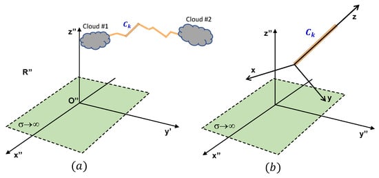
Figure 1.
Coordinate system for single channel segment. Original coordinate system (a); final coordinate system (b).
In the case of a cylindrical coordinate system, the generic channel segment becomes a single vertical line radiator of height h, and the EM fields at observation point P() can be easily derived (see Figure 2). For detailed calculation, in order to derive the analytical expressions in the time domain of both the electric and magnetic field, the reader can refer to [39,51]). In order to clarify the solution method, a step-by-step procedure is described in the Appendix A.
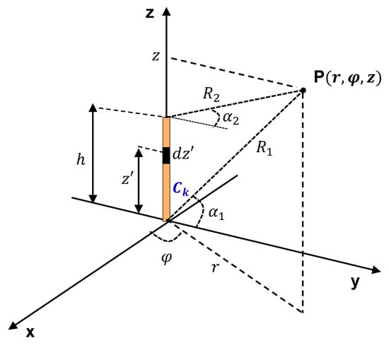
Figure 2.
Generic channel segment and main geometrical parameters in the cylindrical coordinate system .
In particular, E(t) only has the components and , while . If is the time when the step current arrives at the generic channel segment; the expressions of the fields are as follows:
where is the Heaviside step function, c is the speed of light, and v is the velocity of propagation of the step current; all the geometrical parameters are reported in Figure 2. The terms and depend on the quantity
and have the following values:
where
The terms and in Equation (1) represent the contributions to the electric field produced by the charge variation at the bottom and at the upper end of the channel, respectively. Their values are as follows:
Moreover, as already explicitly remarked, the contributions of the “image” channel and of “image” charges also have to be introduced.
As concerns as the magnetic field H(t), due to the symmetry of the considered geometry, the only component different from zero is . The expressions of the fields are as follows:
in which, again, the quantity depends on in Equation (2):
Moreover, in this case, the contribution of the “image” channel has to be summed.
3. Model Validation
For the validation of the model described in the previous section and used for the calculation of EM fields generated in CC lightning, the results were compared to those reported by Rubinstein et al. in [52]. For this reason, a vertical cloud-to-ground channel was considered, and the electric and magnetic fields at ground were determined at two distances from the channel base, namely = 5 km and = 200 km. The vertical channel is travelled by a step current of amplitude at a velocity . The current propagates along the channel according to the transmission line (TL) model [53]; that is, without either distortion or attenuation. The vertical channel was adopted as a benchmark since there is abundance of results about radiated EM fields; however, we remark that it can be used for validation purposes because in our model, it is treated as a special case of a tortuous channel, composed on N vertical segments of equal length h and placed at different heights above the ground plane. In Figure 3, in the left column, we show, respectively, the time evolution of the electric and magnetic field at = 5 km calculated with the equations described above. The waveforms can be compared with those shown in Figure 3b in [52]: they markedly highlight the accuracy of the proposed model. As concerns as the amplitude of the electric field, we observe that here and in the following, only the variation of the field produced by the lightning current is calculated: the static field produced by the charge distribution on the clouds prior to the lightning event is not taken into account. This is a common method for presenting data in the literature. Additionally, in Figure 3, on the right column, we have also plotted the time evolution of both the electric and magnetic fields computed at = 200 km. Again, the comparison with the waveshapes shown in Figure 3c in the paper by Rubinstein et al. [52] demonstrates the accuracy of the adopted model.
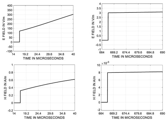
Figure 3.
Electric and magnetic fields computed at = 5 km (left column). Electric and magnetic fields computed at at = 200 km (right column). The waveforms can be compared to those shown in Figure 3 in [52].
4. Numerical Results and Discussion
After the verification of the accuracy of the proposed method, we assessed the capabilities of the proposed model to compute EM fields generated by cloud-to-cloud lightning. In the following, we present the results of numerical simulations obtained by considering an horizontal channel originating from point of Cartesian coordinates [0,0,4000] m travelled by the impulsive current at a velocity m/s. The analytical expression of the current is as follows:
The waveshape of the current is the same as the pulse current adopted in [40]; it is shown in Figure 4. It has a peak amplitude of 20 kA. Please note that as reported in the correction in [40], this is the exact expression of the current, while the analytical formula shown in [40] contains a mistake due to a typographical error. The channel is 2 km long and is located in the plane. The selected characteristics of the channel, the waveform of the travelling current, and its velocity were thee the same as those used by Price et al. in their pioneering paper [40]. The horizontal channel is composed of horizontal segments of equal length = 100 m. The number of horizontal segments has no effect on the accuracy of the numerical results but influences the computational time since the calculation of the total field is obtained by summing up the fields produced by each segment composing the channel. In this case, the number has been chosen only as a reference value for the evaluation of the required CPU time.
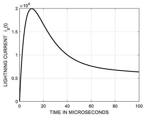
Figure 4.
Waveform of the impulsive current traversing the lightning channel (same as in [40]).
The electric fields were computed at different points above the ground plane at position and in order to take into account the effects of lightning both on objects at ground and on flying objects. Moreover, we also considered the EM fields radiated at the same observation points by a tortuous CC channel in order to highlight the main differences among the fields.
The tortuous path was obtained by randomly defining the number and position of the segments composing it since no 3D data are available in the literature regarding cloud-to-cloud lightning channels. Its average height above the ground is 4000 m, the minimum height is 3950 m, and the maximum height is 4050 m. The tortuous CC channel is composed of segments whose mean length is = 35 m. In order to clarify the considered geometry, the channels and the observation points are shown in Figure 5. In the authors’ opinion, the presence of an “artificial” channel cannot be considered as a limitation because the proposed paper is not focused on presenting a new theoretical model for cloud-to-cloud lightning but rather on proposing a model for EM field calculation.
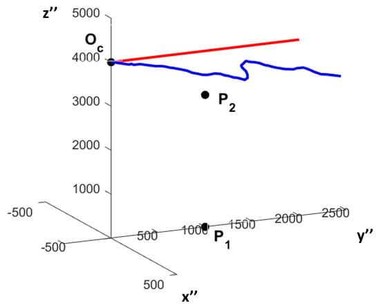
Figure 5.
Observation points and . Tortuous (blue) and horizontal (red) channels.
The fields were computed in a time window of 100 s with a time step = 2 ns, resulting in a total number of 50,000 samples for each component of both the electric and magnetic fields. The required computational time for the calculation of the step response, obtained by implementing all calculations in a ®MATLAB environment and by using a Microsoft Window 11 personal computer equipped with 16 GB of RAM and an Intel I7-8700 3.2 GHz processor, was about = 2.6 s for the calculation of the fields produced by the horizontal channel and about = 7.5 s in the case of the tortuous path. The convolution integration was performed in about = 0.3 s for both the horizontal channel and for the tortuous one. As concerns as the observation point , due to the hypothesis of a perfectly conductive ground, the horizontal component of the electric field in the reference system is always zero. Figure 6 shows the vertical component created by the horizontal (red) and tortuous (blue) lightning channels. The effect of tortuosity is clearly visible in the jagged shape of the electric field waveform, which presents “humps” following the initial peak. Every kink in the lightning channel has, as a consequence, a variation in the direction of propagation of the current and, accordingly, a rapid change in the electric field: as a result, the fine structure of the electric field waveform reflects the tortuosity of the channel.
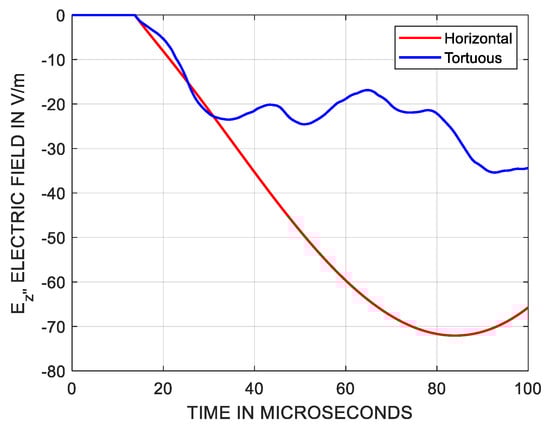
Figure 6.
Vertical component of the electric field at due to an horizontal (red) and a tortuous (blue) CC channel.
Similar conclusions can be drawn from the analysis of the time evolution of the horizontal components and of the magnetic field shown in Figure 7. In particular, the lightning current flowing along a tortuous channel gives rise to a component which has the same order of magnitude of the component. Conversely, due to the geometrical symmetry, the component of the magnetic field produced by an horizontal path is always zero. Furthermore, we can observe that the fine structure in the magnetic field waveforms is more pronounced than in those in the electric field, probably due to the absence of the “masking” effect on the fields produced by the static charge variation on the clouds. The component also presents a zero-crossing and a polarity reversal, which is due to the geometry of the channel. The vertical component of the magnetic field is not shown for both channels because it is always negligible due to the relative position of the observation point (situated in the plane) with respect to the lightning path (which mainly evolves in the same plane).
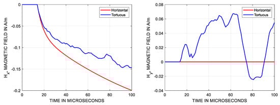
Figure 7.
Horizontal components of the magnetic field ( on the left and on the right) computed at observation point and produced by a horizontal (red) and a tortuous (blue) CC channel.
When considering the second observation point , we can notice that both channels produce a vertical () and a horizontal () component of the electric field Figure 8. Moreover, in the case of a tortuous path, the component also arises. However, the fine structure of the field is not evident probably because, at a closer distance from the channel, the effect of kinks is masked by the variation of static charge on the cloud. As concerns as the magnetic field, differently from the case of an horizontal channel, all the Cartesian components of the field are present, and their amplitude is in the same order magnitude. This is an important effect to consider because it proves that the EM shielding performance of devices located above the ground can be discernibly affected by the geometrical structure of the channel. In this case, it is also important to highlight that the fine structure of the field waveforms computed at close distance from the channel is less influenced by the channel tortuosity with respect to further observation points. Further investigations could be carried out by taking into account the effects of other important physical parameters, such as the velocity of the travelling current, its waveform, the propagation mechanism along the channel, the position of the observation point, and the geometry of the lightning path. Nevertheless, this sort of survey is beyond the scope of the present paper and will be the objective of upcoming studies. Moreover, it should be noted that considerable effort is needed to the complete the experimental verification of the model and the tuning of its parameters: given a channel current, the model should be able to reproduce the radiated EM fields. In the case of cloud-to-ground lightning, such a validation is usually performed using the triggered lightning technique [54], according to which lightning is initiated by the launching towards the cloud of a small rocket pulling a metal wire from the ground. Although the technique produces “semiartificial” lightning, it has provided interesting results concerning the lightning electromagnetic environment, return-stroke speed, electric fields in the immediate vicinity of the channel, interaction with ground and grounding objects, etc. [55]. Unfortunately, such a technique has inherent difficulties of application in the case of cloud-to-cloud events. Alternatively, the validation of the theoretical model could be performed by using suitable reduced-scale models able to model systems characterised by structural and topological complexity. A procedure for the evaluation of the scale factor for power distribution systems involved in an indirect-lightning event can be found in [56].
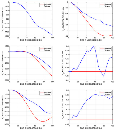
Figure 8.
Electric (left) and magnetic (right) field components computed at observation point and produced by a horizontal (red) and a tortuous (blue) CC channel.
5. Conclusions
The analytical formulas for the computation in the time domain of electromagnetic (EM) fields generated by tortuous cloud-to-cloud (CC) lightning channels over a perfectly conducting ground have been presented, together with a detailed, step-by-step procedure of the calculation for each segment composing a lightning channel. The waveforms of the electric and magnetic field components sensibly differ from those produced by a horizontal path and reflect the tortuosity of the channel. In particular, the fine structure of the fields is evidenced in the time evolution of the magnetic field components, while it is mitigated in the electric field waveforms in proximity to the channel due to the masking effect of the field produced by the static charge variation in the clouds. The presence of the three components of the fields support the notion that the proposed tool is essential for the evaluation of the hazards to electric and electronic devices or for the estimation of the induced voltages produced by CC lightning Work is in progress to derive EM fields signatures as a function of the observation point at different distances, elevations, and azimuth angles. Moreover, a further extension of the research activity will be the introduction to the model of a finitely conducting ground.
Author Contributions
Conceptualization, C.P., A.A., and L.V.; methodology, C.P. and L.V.; software, C.P. and M.B.; validation, all authors; formal analysis, all authors; writing—original draft preparation, all authors; writing—review and editing, all authors. All authors have read and agreed to the published version of the manuscript.
Funding
This research was funded by the NEST project in the framework of PNRR funding.
Data Availability Statement
The data presented in this study are available on request from the corresponding author.
Conflicts of Interest
The authors declare no conflict of interest.
Appendix A
In this Appendix, a typical example of field calculation is reported, together with the description of the main steps needed. For the sake of brevity, we only refer to the computation of the magnetic field at observation point and produced by the tortuous channel described in Section 4. Similar steps can be carried out for the electric field and for any other observation point.
According to the proposed procedure, the magnetic field must be calculated by summing up the contributions of each segment composing the lightning channel and of each segment composing its image. The following steps are thus involved:
- Selection of the channel segment. As an example, in the following the procedure, channel segment involving is illustrated. Figure A1a shows the selected segment . The origin of the segment and the opposite endpoint have, respectively, the following coordinates (in metres) ([263.4, 1012.5, 4010.8]) and ([248.1, 1051.5, 4092.0]) with respect to the original Cartesian coordinate system .
- Adoption of a cylindrical coordinate system. A new coordinate system is obtained by translating the origin in (Figure A1a); the elevation and azimuth angles are then calculated. Afterwards, the coordinate system is first rotated counterclockwise around the -axis by an angle . The rotation is described by the rotation matrix :Soon after, the obtained coordinate system is further rotated clockwise around the -axis by the angle . The corresponding rotation matrix is computed:With these two consecutive rotations, characterized by the rotation matrix , a new Cartesian coordinate system is obtained (Figure A1b). The final cylindrical coordinate system is easily deduced; it has the the z-axis coincident with the direction of the selected segment . The coordinates of the observation point in the cylindrical system become ([r = 902.2 m, , z = 665.3 m]).
- Calculation of the field. The step response of the magnetic field is then calculated in the cylindrical coordinate system by using the expressions in Equations (2), (5), (8) and (9). In such a system, the only component different from zero is . Its waveform is shown in Figure A2a. Note that in the above equations is the time instant in which the step current arrives at channel segment . For a correct expression of the field, the propagation time of the step current along the channel must be taken into account. The current starts from the cloud, moves at velocity m/s, and travels the distance d = 1384.9 m before arriving at segment after a propagation time = 69.2 s. For this reason, the time evolution of the magnetic field is the one depicted in Figure A2b: it is the same as that in Figure A2a, but it is shifted in time.
- Computation of the field in the original Cartesian coordinate system . First, the components , , and of the magnetic field in the reference system are evaluated, and then the computation of the Cartesian components in is easily carried out if the inverse of the rotation matrix A is known:The time evolution of the step response , , and for each component of the magnetic field is shown in Figure A3a.
- Calculation of the field produced by the image channel. Since the model is based upon the hypothesis of a perfectly conducting ground, the method of images is adopted. Steps 1, 2, 3, and 4 are repeated for each segment composing the image channel. In the case of the image segment , the coordinates of the observation point in the relative cylindrical system become ([r = 5883.5 m, , z = 3968.1 m]). The step response in the original Cartesian coordinate system produced by the image channel is depicted in Figure A3b.
- Computation of the step response.The step response, due to the superposition principle, is the sum of the response of the lightning channel and of its image. Figure A4 shows the three components of the magnetic field. By using convolution integration, it is possible to obtain the field shown in Figure 8.

Figure A1.
(a) Cartesian coordinate systems and . (b) Cartesian coordinate system R. The channel segment (in orange colour).
Figure A1.
(a) Cartesian coordinate systems and . (b) Cartesian coordinate system R. The channel segment (in orange colour).


Figure A2.
(a) Step response of magnetic field produced by the channel segment . (b) Step response when the propagation time of the current along the lightning channel is taken into account.
Figure A2.
(a) Step response of magnetic field produced by the channel segment . (b) Step response when the propagation time of the current along the lightning channel is taken into account.


Figure A3.
Cartesian components of the step response produced by the lightning channel (a). Cartesian components of the step response produced by the image channel (b).
Figure A3.
Cartesian components of the step response produced by the lightning channel (a). Cartesian components of the step response produced by the image channel (b).


Figure A4.
Step response of the magnetic field produced by the tortuous channel.
Figure A4.
Step response of the magnetic field produced by the tortuous channel.

References
- Franklin, B. Experiments and Observations on Electricity, Made at Philadelphia in America; E. Cave: London, UK, 1751. [Google Scholar]
- Wilson, C. On some determinations of the sign and magnitude of electric discharges in lightning flashes. Proc. R. Soc. A 1916, 92, 555–574. [Google Scholar]
- Boys, C. Progressive Lightning. Nature 1926, 118, 749–750. [Google Scholar] [CrossRef]
- Schonland, B.; Collens, H. Development of the Lightning Discharge. Nature 1933, 132, 407–408. [Google Scholar] [CrossRef]
- Cooper, M. Emergent Care of Lightning and Electrical Injuries. Semin. Neurol. 1995, 15, 268–278. [Google Scholar] [CrossRef]
- Cooray, V.; Cooray, C.; Andrews, C. Lightning caused injuries in humans. J. Electrost. 2007, 65, 386–394. [Google Scholar] [CrossRef]
- Nucci, C.; Rachidi, F.; Ianoz, M.; Mazzetti, C. Lightning-induced voltages on overhead lines. IEEE Trans. Electromagn. Compat. 1993, 35, 75–86. [Google Scholar] [CrossRef]
- Andreotti, A.; Assante, D.; Mottola, F.; Verolino, L. An Exact Closed-Form Solution for Lightning-Induced Overvoltages Calculations. IEEE Trans. Power Deliv. 2009, 24, 1328–1343. [Google Scholar] [CrossRef]
- Andreotti, A.; Petrarca, C.; Rakov, V.A.; Verolino, L. Calculation of Voltages Induced on Overhead Conductors by Nonvertical Lightning Channels. IEEE Trans. Electromagn. Compat. 2012, 54, 860–870. [Google Scholar] [CrossRef]
- Formisano, A.; Hernández, J.C.; Petrarca, C.; Sanchez-Sutil, F. Modeling of PV Module and DC/DC Converter Assembly for the Analysis of Induced Transient Response Due to Nearby Lightning Strike. Electronics 2021, 10, 120. [Google Scholar] [CrossRef]
- Mohammed, Z.; Hizam, H.; Gomes, C. Lightning-induced transient effects in a hybrid PV–wind system and mitigation strategies. Electr. Power Syst. Res. 2019, 174, 105882. [Google Scholar] [CrossRef]
- Paolone, M.; Petrache, E.; Rachidi, F.; Nucci, C.; Rakov, V.; Uman, M.; Jordan, D.; Rambo, K.; Jerauld, J.; Nyffeler, M.; et al. Lightning induced disturbances in buried cables—Part II: Experiment and model validation. IEEE Trans. Electromagn. Compat. 2005, 47, 509–520. [Google Scholar] [CrossRef]
- Formisano, A.; Hernández, J.C.; Petrarca, C.; Sanchez-Sutil, F. Assessment of induced voltages in common and differential-mode for a PV module due to nearby lightning strikes. IET Renew. Power Gener. 2019, 13, 1369–1378. [Google Scholar] [CrossRef]
- Rakov, V.; Uman, M. Lightning. Physics and Effects; Cambridge University Press: Cambridge, UK, 2003. [Google Scholar]
- Bazelyan, E.; Raizer, Y. Lightning Physics and Lightning Protection; IOP Publishing: Bristol, UK; Philadelphia, PA, USA, 2000. [Google Scholar]
- Uman, M.; Rakov, V. The interaction of lightning with airborne vehicles. Prog. Aerosp. Sci. 2003, 39, 61–81. [Google Scholar] [CrossRef]
- Larsson, A. The interaction between a lightning flash and an aircraft in flight. Comptes Rendus Phys. 2002, 3, 1423–1444. [Google Scholar] [CrossRef]
- Gagné, M.; Therriault, D. Lightning strike protection of composites. Prog. Aerosp. Sci. 2014, 64, 1–16. [Google Scholar] [CrossRef]
- Zhao, Z.; Zhang, B.; Du, Y.; Hei, Y.; Yi, X.; Shi, F.; Xian, G. MWCNT modified structure-conductive composite and its electromagnetic shielding behavior. Compos. Part B Eng. 2017, 130, 21–27. [Google Scholar] [CrossRef]
- Perala, R.A.; Rudolph, T.; Erolsen, F. Electromagnetic Interaction of Lightning with Aircraft. IEEE Trans. Electromagn. Compat. 1982, EMC-24, 173–203. [Google Scholar] [CrossRef]
- Van Schalkwyk, V.; Gomes, C.; van Coller, C. The Effect of Cloud-to-Cloud Lightning on Medium Voltage Lines. In Proceedings of the 2022 36th International Conference on Lightning Protection (ICLP), Cape Town, South Africa, 2–7 October 2022; pp. 14–19. [Google Scholar] [CrossRef]
- Willett, J.; Levine, D.; Idone, V. Lightning return stroke current waveforms aloft from measured field change, current, and channel geometry. J. Geophys. Res. Atmos. 2008, 113, 7. [Google Scholar] [CrossRef]
- Kodali, V.; Rakov, V.; Uman, M.; Rambo, K.; Schnetzer, G.; Schoene, J.; Jerauld, J. Triggered-lightning properties inferred from measured currents and very close electric fields. Atmos. Res. 2005, 76, 355–376. [Google Scholar] [CrossRef]
- Kutsuna, K.; Nagaoka, N.; Baba, Y.; Tsuboi, T.; Rakov, V. Estimation of lightning channel-base current from far electromagnetic field in the case of inclined channel. Electr. Power Syst. Res. 2023, 214, 108854. [Google Scholar] [CrossRef]
- Nucci, C. The Lightning Induced Over-Voltage (LIOV) code. In Proceedings of the 2000 IEEE Power Engineering Society Winter Meeting, Conference Proceedings (Cat. No.00CH37077), Columbus, OH, USA, 28 January–1 February 2000; Volume 4, pp. 2417–2418. [Google Scholar] [CrossRef]
- Uman, M.; McLain, D.; Krider, E. The electromagnetic radiation from a finite antenna. Am. J. Phys. 1975, 43, 33–38. [Google Scholar] [CrossRef]
- Andreotti, A.; Piantini, A.; Pierno, A.; Rizzo, R. Lightning-Induced Voltages on Complex Power Systems by Using CiLIV: The Effects of Channel Tortuosity. IEEE Trans. Power Deliv. 2018, 33, 680–688. [Google Scholar] [CrossRef]
- Petrache, E.; Rachidi, F.; Paolone, M.; Nucci, C.; Rakov, V.; Uman, M. Lightning induced disturbances in buried Cables-part I: Theory. IEEE Trans. Electromagn. Compat. 2005, 47, 498–508. [Google Scholar] [CrossRef]
- De Magistris, M.; di Bernardo, M.; Manfredi, S.; Petrarca, C.; Yaghouti, S. Modular experimental setup for real-time analysis of emergent behavior in networks of Chua’s circuits. Int. J. Circuit Theory Appl. 2016, 44, 1551–1571. [Google Scholar] [CrossRef]
- Lauria, D.; Pagano, M.; Petrarca, C. Transient Thermal Modelling of HV XLPE Power Cables: Matrix approach and experimental validation. In Proceedings of the 2018 IEEE Power and Energy Society General Meeting (PESGM), Portland, OR, USA, 5–10 August 2018; pp. 1–6. [Google Scholar] [CrossRef]
- Borghetti, A.; Morched, A.; Napolitano, F.; Nucci, C.A.; Paolone, M. Lightning-Induced Overvoltages Transferred Through Distribution Power Transformers. IEEE Trans. Power Deliv. 2009, 24, 360–372. [Google Scholar] [CrossRef]
- Hernandez, J.C.; Vidal, P.G.; Jurado, F. Lightning and Surge Protection in Photovoltaic Installations. IEEE Trans. Power Deliv. 2008, 23, 1961–1971. [Google Scholar] [CrossRef]
- Perrin, E.; Guiffaut, C.; Reineix, A.; Tristant, F. Using a Design-of-Experiment Technique to Consider the Wire Harness Load Impedances in the FDTD Model of an Aircraft Struck by Lightning. IEEE Trans. Electromagn. Compat. 2013, 55, 747–753. [Google Scholar] [CrossRef]
- De Vivo, B.; Lamberti, P.; Tucci, V.; Petrarca, C. Simulation of the Bearing Voltage in an Inverter-Fed Induction Motor by a Full Three Phase Multi Conductor Transmission Line Model. Prog. Electromagn. Res. B 2013, 46, 233–250. [Google Scholar] [CrossRef]
- Yang, G.; Yao, J.; Dong, Z. Neuroadaptive learning algorithm for constrained nonlinear systems with disturbance rejection. Int. J. Robust Nonlinear Control. 2022, 32, 6127–6147. [Google Scholar] [CrossRef]
- Fotis, G.; Ekonomou, L.; Maris, T.; Liatsis, P. Development of an artificial neural network software tool for the assessment of the electromagnetic field radiating by electrostatic discharges. IET Sci. Meas. Technol. 2007, 1, 261–269. [Google Scholar] [CrossRef]
- Ledari, S.; Mirzaie, M. Sheath induced voltage prediction of high voltage cable based on artificial neural network. Comput. Electr. Eng. 2020, 87, 106788. [Google Scholar] [CrossRef]
- Zhu, Y.; Bitzer, P.; Rakov, V.; Ding, Z. A Machine-Learning Approach to Classify Cloud-to-Ground and Intracloud Lightning. Geophys. Res. Lett. 2021, 48, 1148. [Google Scholar] [CrossRef]
- Lupo, G.; Petrarca, C.; Tucci, V.; Vitelli, M. EM fields generated by lightning channels with arbitrary location and slope. IEEE Trans. Electromagn. Compat. 2000, 42, 39–53. [Google Scholar] [CrossRef]
- Price, H.; Agrawal, A. The Response of a Transmission Line Illuminated by Lightning-Induced Electromagnetic Fields. IEEE Trans. Electromagn. Compat. 1980, EMC-22, 150–156, Correction to IEEE Trans. Electromagn. Compat. 1981, EMC-23, 160. [Google Scholar] [CrossRef]
- Petrarca, C.; Minucci, S.; Andreotti, A. On the Influence of Channel Tortuosity on Electric Fields Generated by Lightning Return Strokes at Close Distance. Prog. Electromagn. Res. B 2017, 74, 61–75. [Google Scholar] [CrossRef]
- Andreotti, A.; De Martinis, U.; Petrarca, C.; Rakov, V.A.; Verolino, L. Lightning electromagnetic fields and induced voltages: Influence of channel tortuosity. In Proceedings of the 2011 XXXth URSI General Assembly and Scientific Symposium, Istanbul, Turkey, 13–20 August 2011; pp. 1–4. [Google Scholar] [CrossRef]
- Izadi, M.; Kadir, M.Z.A.A.; Gomes, C. Evaluation of Electromagnetic Fields Associated with Inclined Lightning Channel Using Second Order FDTD-Hybrid Methods. Prog. Electromagn. Res. 2011, 117, 209–236. [Google Scholar] [CrossRef]
- Brignone, M.; Procopio, R.; Mestriner, D.; Rossi, M.; Delfino, F.; Rachidi, F.; Rubinstein, M. Analytical Expressions for Lightning Electromagnetic Fields With Arbitrary Channel-Base Current—Part I: Theory. IEEE Trans. Electromagn. Compat. 2021, 63, 525–533. [Google Scholar] [CrossRef]
- Brignone, M.; Nicora, M.; Mestriner, D.; Procopio, R.; Petrarca, C.; Formisano, A.; Barmada, S.; Delfino, F. An Efficient Method for the Computation of Electromagnetic Fields Associated With Tortuous Lightning Channels. IEEE Trans. Electromagn. Compat. 2022, 64, 1431–1441. [Google Scholar] [CrossRef]
- Sommerfeld, A. Uber die ausbreitung der Wellen in der drahtlosen Telegraphie. Ann. Phys. 1909, 28, 665. [Google Scholar] [CrossRef]
- Delfino, F.; Procopio, R.; Rossi, M. Lightning return stroke current radiation in presence of a conducting ground: 1. Theory and numerical evaluation of the electromagnetic fields. J. Geophys. Res. Atmos. 2008, 113, D5. [Google Scholar] [CrossRef]
- Thomson, E.; Medelius, P.; Rubinstein, M.; Uman, M.; Johnson, J.; Stone, J. Horizontal electric fields from lightning return strokes. J. Geophys. Res. Atmos. 1988, 93, 2429–2441. [Google Scholar] [CrossRef]
- Cooray, V. Horizontal fields generated by return strokes. Radio Sci. 1992, 27, 529–537. [Google Scholar] [CrossRef]
- Rubinstein, M. An approximate formula for the calculation of the horizontal electric field from lightning at close, intermediate, and long range. IEEE Trans. Electromagn. Compat. 1996, 38, 531–535. [Google Scholar] [CrossRef]
- Lupo, G.; Petrarca, C.; Tucci, V.; Vitelli, M. EM fields associated with lightning channels: On the effect of tortuosity and branching. IEEE Trans. Electromagn. Compat. 2000, 42, 394–404. [Google Scholar] [CrossRef]
- Rubinstein, M.; Uman, M. Methods for calculating the electromagnetic fields from a known source distribution: Application to lightning. IEEE Trans. Electromagn. Compat. 1989, 31, 183–189. [Google Scholar] [CrossRef]
- Rakov, V.; Uman, M. Review and evaluation of lightning return stroke models including some aspects of their application. IEEE Trans. Electromagn. Compat. 1998, 40, 403–426. [Google Scholar] [CrossRef]
- Fieux, R.P.; Gary, C.H.; Hutzler, B.P.; Eybert-Berard, A.R.; Hubert, P.L.; Meesters, A.C.; Perroud, P.H.; Hamelin, J.H.; Person, J.M. Research on Artificiallyu Triggered Lightning in France. IEEE Trans. Power Appar. Syst. 1978, PAS-97, 725–733. [Google Scholar] [CrossRef]
- Rakov, V.; Uman, M.; Rambo, K. A review of ten years of triggered-lightning experiments at Camp Blanding, Florida. Atmos. Res. 2005, 76, 503–517. [Google Scholar] [CrossRef]
- Piantini, A.; Janiszewski, J.; Borghetti, A.; Nucci, C.; Paolone, M. A Scale Model for the Study of the LEMP Response of Complex Power Distribution Networks. IEEE Trans. Power Deliv. 2007, 22, 710–720. [Google Scholar] [CrossRef]


Disclaimer/Publisher’s Note: The statements, opinions and data contained in all publications are solely those of the individual author(s) and contributor(s) and not of MDPI and/or the editor(s). MDPI and/or the editor(s) disclaim responsibility for any injury to people or property resulting from any ideas, methods, instructions or products referred to in the content. |
© 2023 by the authors. Licensee MDPI, Basel, Switzerland. This article is an open access article distributed under the terms and conditions of the Creative Commons Attribution (CC BY) license (https://creativecommons.org/licenses/by/4.0/).