
A Linear Quadratic Integral Controller for PV-Module Voltage Regulation for the Purpose of Enhancing the Classical Incremental Conductance Algorithm
 , , ,
, , ,
Abstract
:1. Introduction
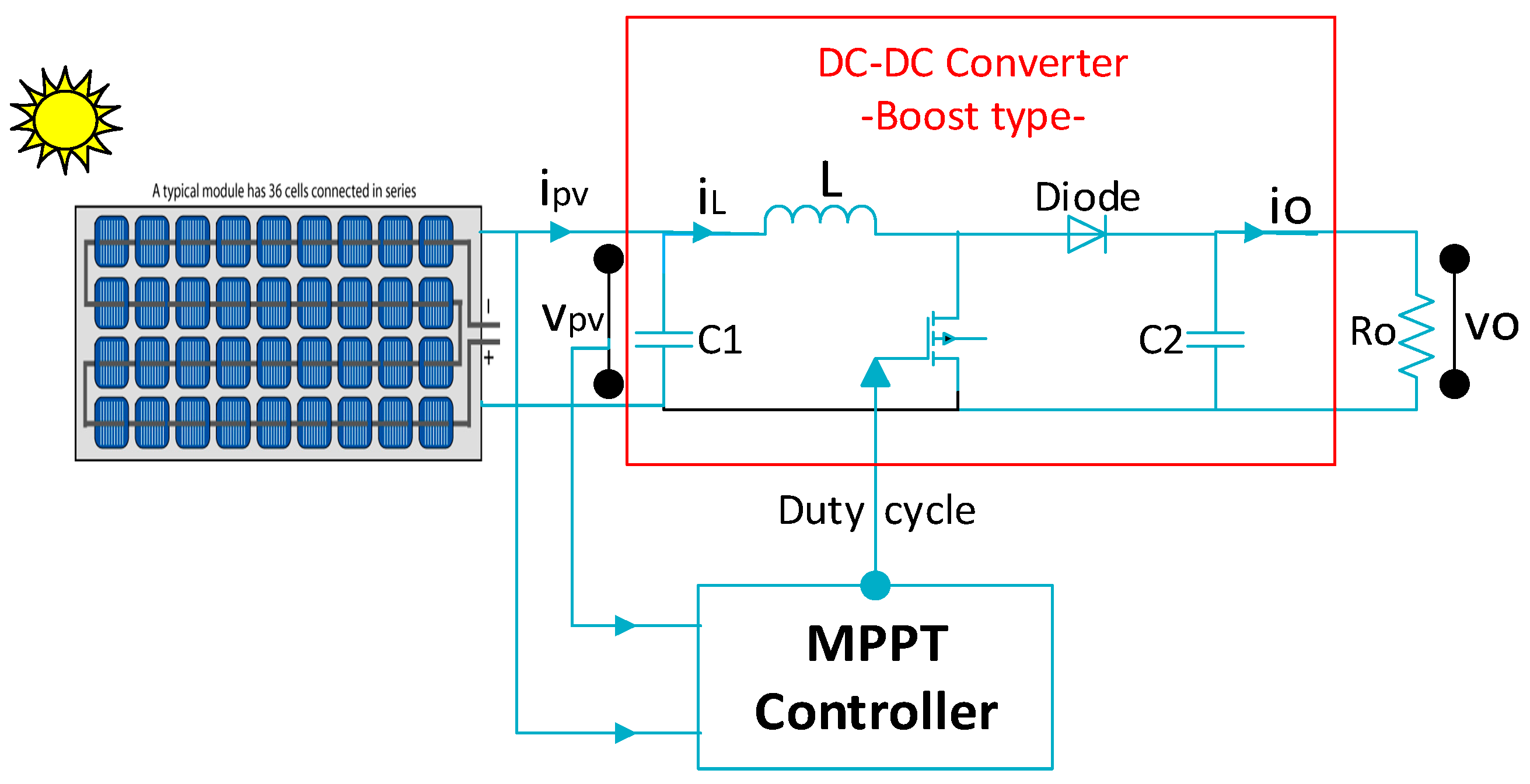
2. Stand-Alone Photovoltaic System Description and Modeling
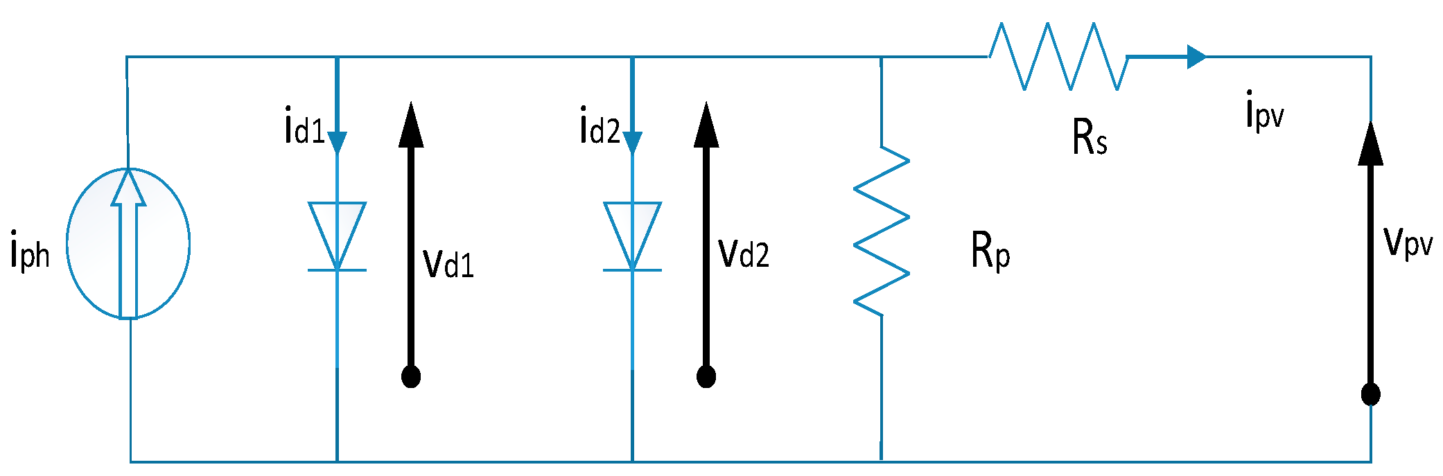
2.1. PV-Module Modeling and Electrical Properties
- iph = S·isc: photo-generated current (A). S is the irradiance.
- isat1, isat2: diode saturation currents (A). Their mathematical formulas and parameters are detailed in [17].
- n1, n2: ideality factors of the diodes
- Ns: number of PV-cells connected in series
- Np: number of PV-cells connected in parallel
- k: constant of Boltzmann (1.3806503 × 10⁻²³ J/K)
- T: temperature (K)
- q: charge of electron (1.60217646 × 10⁻¹⁹ Coulombs)
2.2. Modeling of DC-DC Boost Converter
3. Implementation of MPPT Algorithms
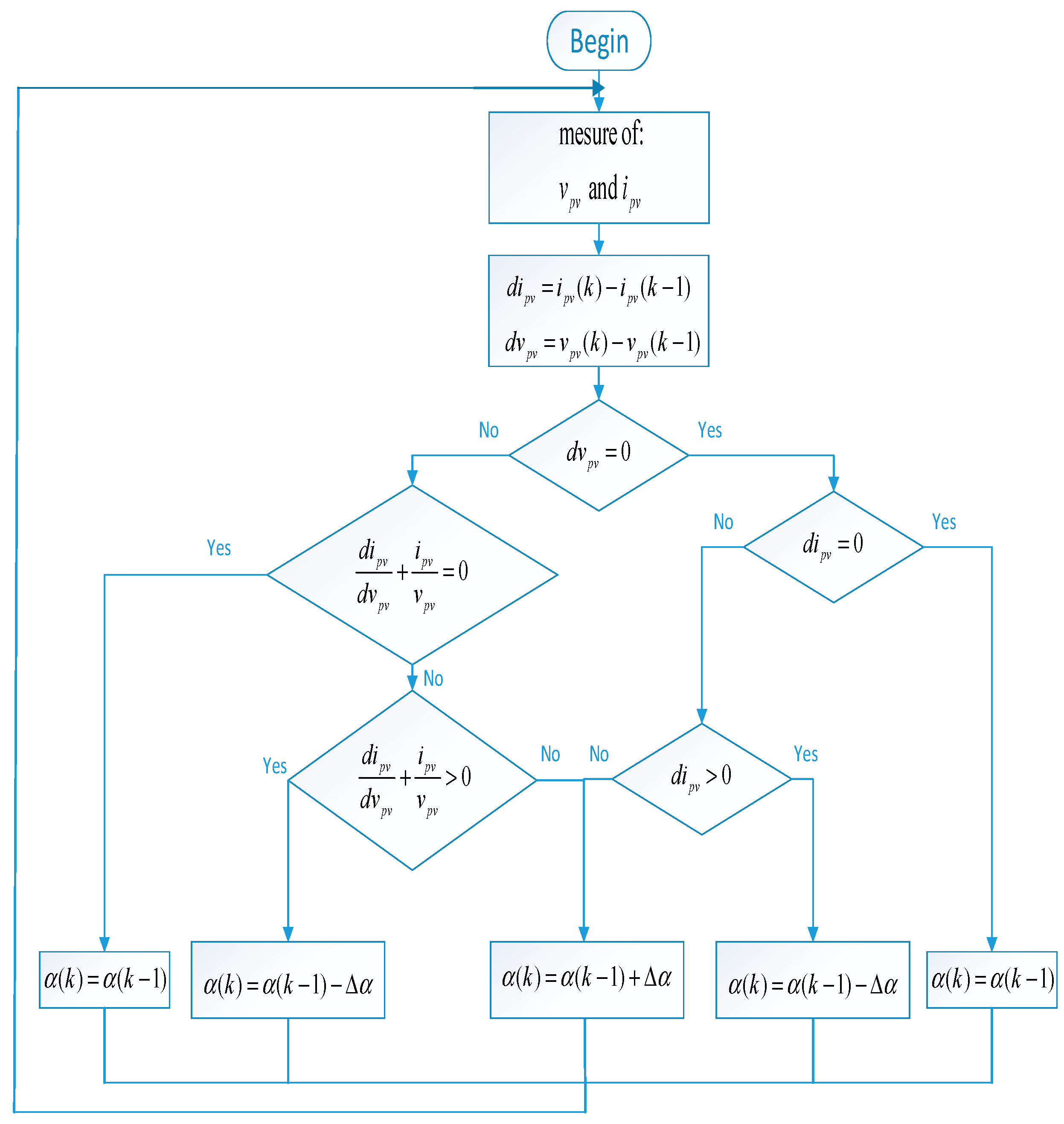
3.1. One Stage Classical IC Algorithm
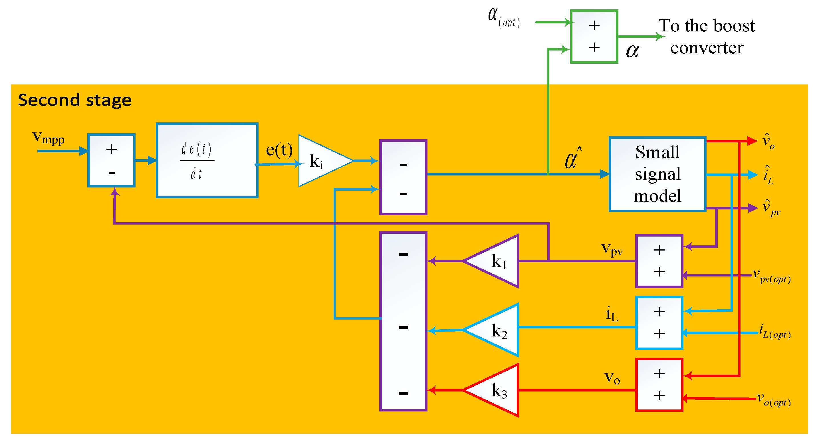
3.2. Hybrid MPPT Algorithm
- (a)
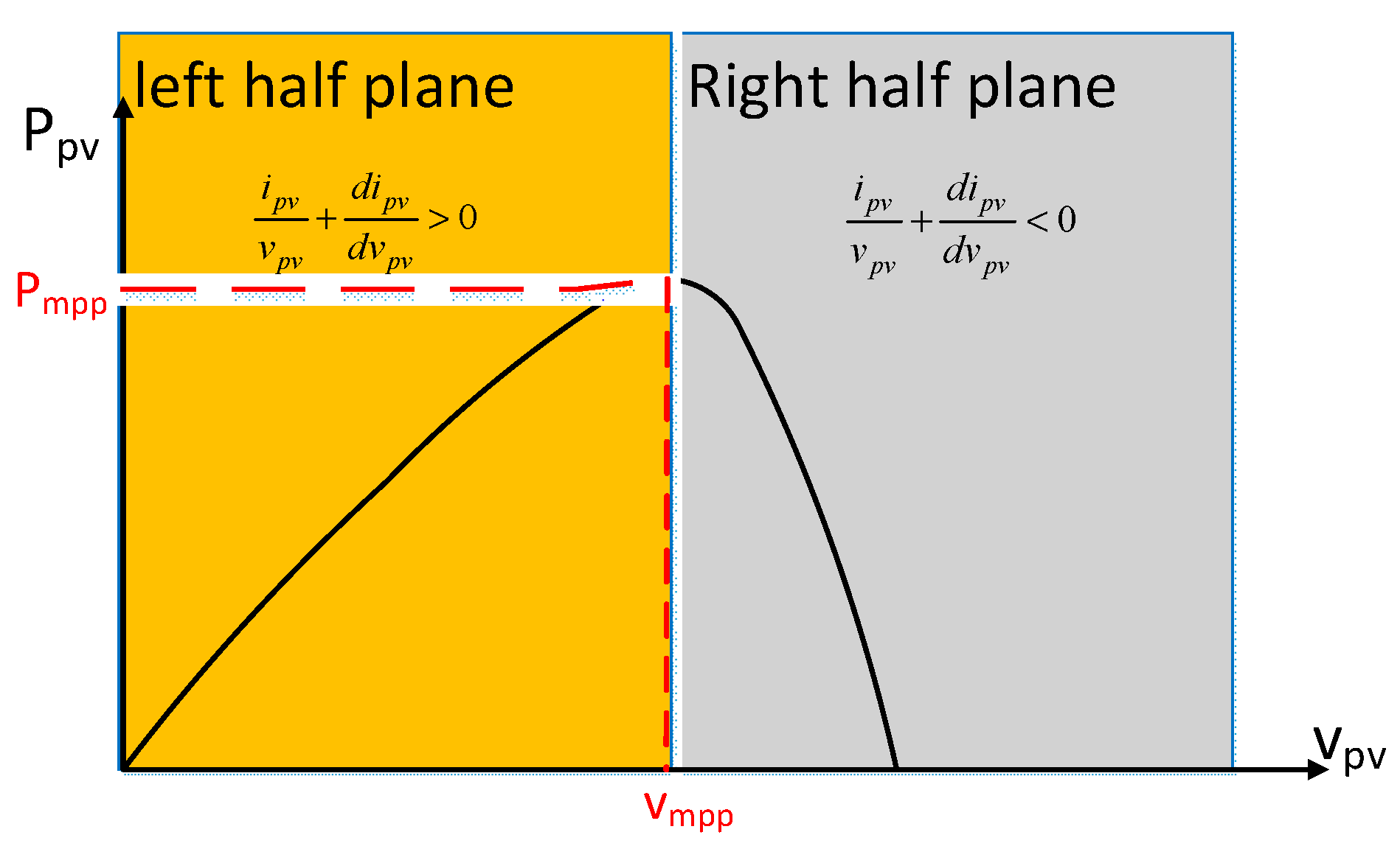
- when , the vmpp(k) must be equal to . This implies that the operating point of the PV-module is in the left half plane (see Figure 6). In order to reach the MPP, the voltage must be increased.
- (b)
- when , the vmpp(k) must be equal to . This implies that the operating point of the PV-module is in the right half plane (see Figure 6). In order to reach the MPP, the voltage must be reduced.
Hybrid IC-LQI Algorithm
- a-
- State-space representation of error dynamics
- b-
- LQI controller design
4. Simulation Results and Discussion
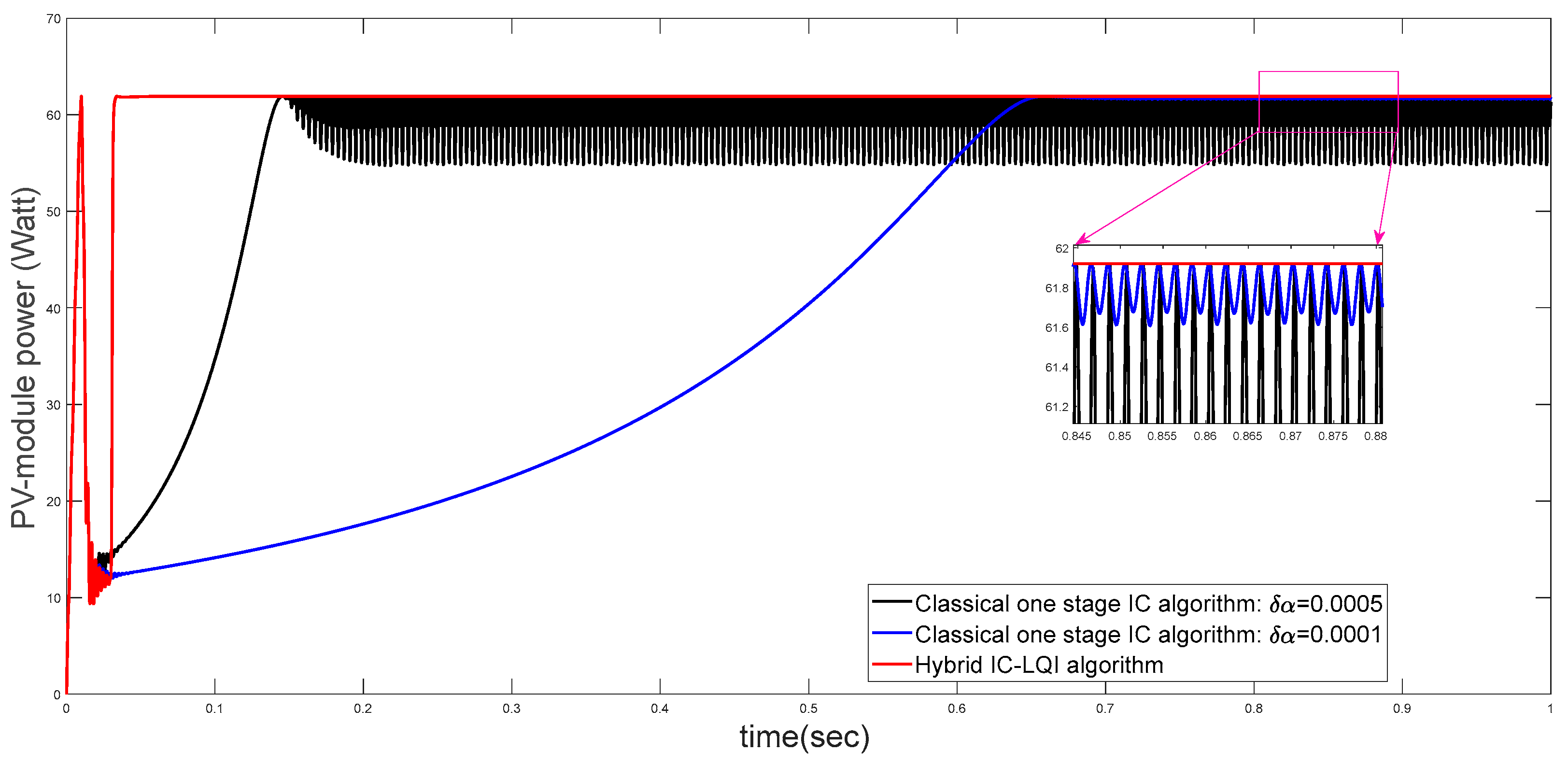
4.1. First Test Scenario: Simulation under Standard Test Condition (STC)
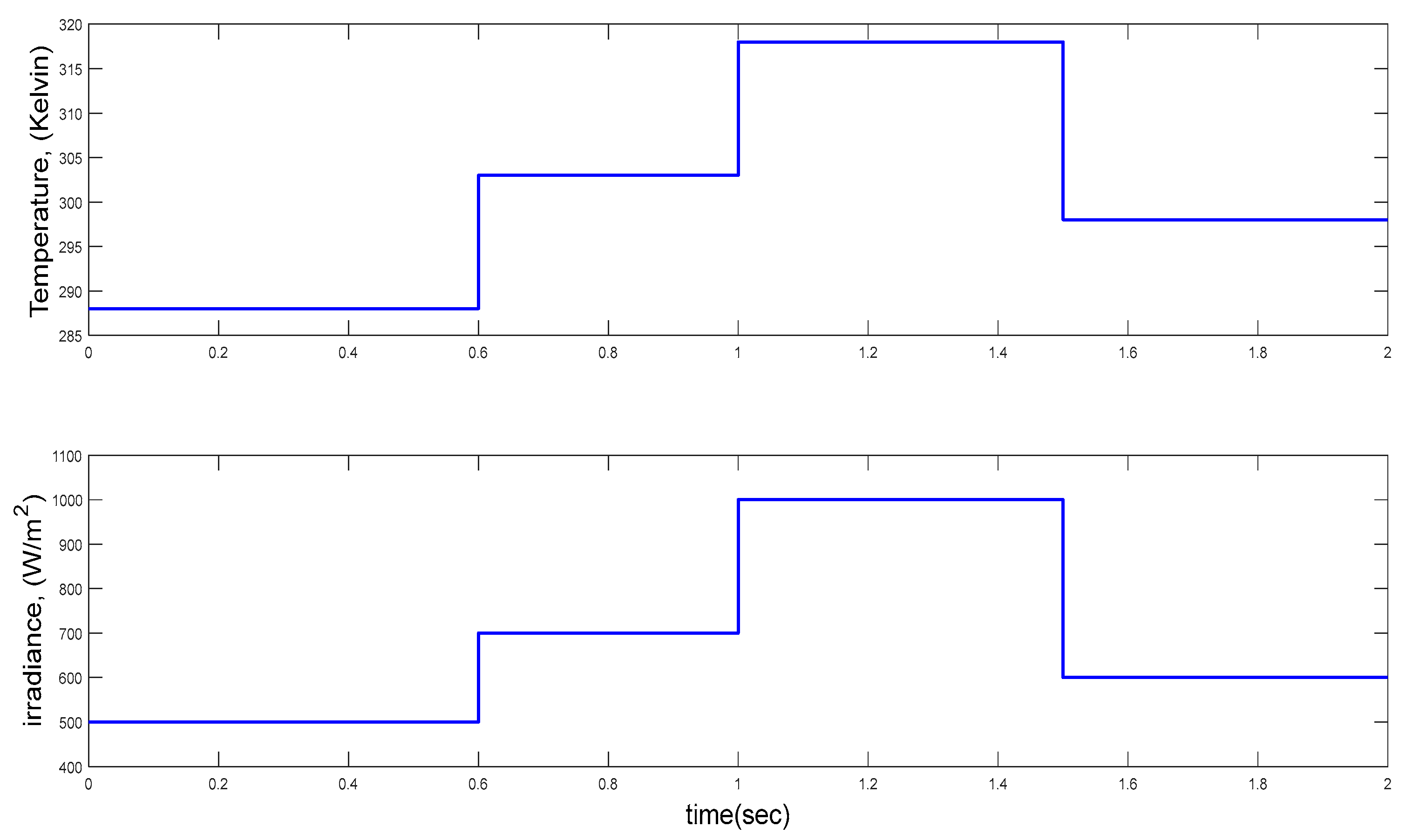
4.2. Second Test Scenario: Simulation under Step Changes of Both Temperature and Irradiance
4.3. Third Test Scenario: Simulation with Step Changes in Both Weather and Load
4.4. Quantitative Comparison Based on Efficiency Criteria
5. Conclusions
Author Contributions
Funding
Data Availability Statement
Conflicts of Interest
References
- Zahedi, A. Solar photovoltaic (PV) energy; latest developments in the building integrated and hybrid PV systems. Renew. Energy 2006, 31, 711–718. [Google Scholar] [CrossRef]
- Salam, Z.; Ahmed, J.; Merugu, B.S. The application of soft computing methods for MPPT of PV system: A technological and status review. Appl. Energy 2013, 107, 135–148. [Google Scholar] [CrossRef]
- Li, G.; Jin, Y.; Akram, M.; Chen, X.; Ji, J. Application of bio-inspired algorithms in maximum power point tracking for PV systems under partial shading conditions—A review. Renew. Sustain. Energy Rev. 2018, 81, 840–873. [Google Scholar] [CrossRef]
- Ilyas, A.; Ayyub, M.; Khan, M.R.; Husain, M.A.; Jain, A. Hardware implementation of perturb and observe maximum power point tracking algorithm for solar photovoltaic system. Trans. Electr. Electron. Mater. 2018, 19, 222–229. [Google Scholar] [CrossRef]
- Safari, A.; Mekhilef, S. Simulation and hardware implementation of incremental conductance MPPT with direct Control method using cuk converter. IEEE Trans. Ind. Electron. 2010, 58, 1154–1161. [Google Scholar] [CrossRef]
- Kivimaki, J.; Kolesnik, S.; Sitbon, M.; Suntio, T.; Kuperman, A. Revisited perturbation frequency design guideline for direct fixed-step maximum power point tracking algorithms. IEEE Trans. Ind. Electron. 2017, 64, 4601–4609. [Google Scholar] [CrossRef]
- Farhat, M.; Barambones, O.; Sbita, L. A real-time implementation of novel and stable variable step size MPPT. Energies 2020, 13, 4668. [Google Scholar] [CrossRef]
- Owusu-Nyarko, I.; Elgenedy, M.A.; Abdelsalam, I.; Ahmed, K.H. Modified variable step-size incremental conductance MPPT technique for photovoltaic systems. Electronics 2021, 10, 2331. [Google Scholar] [CrossRef]
- Singh, P.; Shukla, N.; Gaur, P. Modified variable step incremental-conductance MPPT technique for photovoltaic system. Int. J. Inf. Technol. 2020, 13, 2483–2490. [Google Scholar] [CrossRef]
- Zhang, X.; Li, S.; He, T.; Yang, B.; Yu, T.; Li, H.; Jiang, L.; Sun, L. Memetic reinforcement learning based maximum power point tracking design for PV systems under partial shading condition. Energy 2019, 174, 1079–1090. [Google Scholar] [CrossRef]
- Atia, M.; Ahriche, A.; Bouarroudj, N. Incremental Conductance Algorithm Based On Indirect Control Mode Using An Integrator Controller Tuned by Routh Criterion. In Proceedings of the 2020 6th International Symposium on New and Renewable Energy (SIENR), Ghardaia, Algeria, 13–14 October 2021; pp. 1–5. [Google Scholar] [CrossRef]
- Bouarroudj, N.; Benlahbib, B.; Houam, Y.; Sedraoui, M.; Batlle, V.F.; Abdelkrim, T.; Boukhetala, D.; Boudjema, F. Fuzzy based incremental conductance algorithm stabilized by an optimal integrator for a photovoltaic system under varying operating conditions. Energy Sources Part A Recover. Util. Environ. Eff. 2021, 1–26. [Google Scholar] [CrossRef]
- Bouarroudj, N.; Benlahbib, B.; Sedraoui, M.; Feliu-Batlle, V.; Bechouat, M.; Boukhetala, D.; Boudjema, F. A new tuning rule for stabilized integrator controller to enhance the indirect control of incremental conductance MPPT algorithm: Simulation and practical implementation. Optik 2022, 268, 169728. [Google Scholar] [CrossRef]
- Chiu, C.-S.; Ouyang, Y.-L.; Ku, C.-Y. Terminal sliding mode control for maximum power point tracking of photovoltaic power generation systems. Sol. Energy 2012, 86, 2986–2995. [Google Scholar] [CrossRef]
- Kihal, A.; Krim, F.; Laib, A.; Talbi, B.; Afghoul, H. An improved MPPT scheme employing adaptive integral derivative sliding mode control for photovoltaic systems under fast irradiation changes. ISA Trans. 2018, 87, 297–306. [Google Scholar] [CrossRef] [PubMed]
- Oubbati, B.K.; Boutoubat, M.; Rabhi, A.; Belkheiri, M. Experiential integral backstepping sliding mode controller to achieve the maximum power point of a PV system. Control Eng. Pract. 2020, 102, 104570. [Google Scholar] [CrossRef]
- Bouarroudj, N.; Boukhetala, D.; Feliu-Batlle, V.; Boudjema, F.; Benlahbib, B.; Batoun, B. Maximum power point tracker based on fuzzy adaptive radial basis function neural network for PV-system. Energies 2019, 12, 2827. [Google Scholar] [CrossRef] [Green Version]
- Ishaque, K.; Salam, Z.; Lauss, G. The performance of perturb and observe and incremental conductance maximum power point tracking method under dynamic weather conditions. Appl. Energy 2014, 119, 228–236. [Google Scholar] [CrossRef]
- Karamov, D.N.; Suslov, K.V. Structural optimization of autonomous photovoltaic systems with storage battery replacements. Energy Rep. 2021, 7, 349–358. [Google Scholar] [CrossRef]
- Yousri, D.; Thanikanti, S.B.; Allam, D.; Ramachandaramurthy, V.K.; Eteiba, M. Fractional chaotic ensemble particle swarm optimizer for identifying the single, double, and three diode photovoltaic models’ parameters. Energy 2020, 195, 116979. [Google Scholar] [CrossRef]
- Bouarroudj, N.; Abdelkrim, T.; Farhat, M.; Feliu-Batlle, V.; Benlahbib, B.; Boukhetala, D.; Boudjema, F. Fuzzy logic controller based maximum power point tracking and its optimal tuning in photovoltaic systems. Serbian J. Electr. Eng. 2021, 18, 351–384. [Google Scholar] [CrossRef]
- Nousiainen, L.; Puukko, J.; Mäki, A.; Messo, T.; Huusari, J.; Jokipii, J.; Viinamäki, J.; Lobera, D.T.; Valkealahti, S.; Suntio, T. Photovoltaic generator as an input source for power electronic converters. IEEE Trans. Power Electron. 2012, 28, 3028–3038. [Google Scholar] [CrossRef]
- Shang, L.; Guo, H.; Zhu, W. An improved MPPT control strategy based on incremental conductance algorithm. Prot. Control Mod. Power Syst. 2020, 5, 14. [Google Scholar] [CrossRef]
- Saidi, K.; Maamoun, M.; Bounekhla, M. Simulation and implementation of incremental conductance MPPT algorithm with indirect control method using buck converter. In Proceedings of the 2017 6th International Conference on Systems and Control (ICSC), Batna, Algeria, 7–9 May 2017; pp. 199–204. [Google Scholar] [CrossRef]
- Gurung, N.; Bhattarai, R.; Kamalasadan, S. Optimal linear-quadratic-integral controller design for doubly-fed induction generator. In Proceedings of the 2017 IEEE Power & Energy Society General Meeting, Chicago, IL, USA, 16–20 July 2017; pp. 1–5. [Google Scholar] [CrossRef]
- Okyere, E.; Bousbaine, A.; Poyi, G.T.; Joseph, A.K.; Andrade, J.M. LQR controller design for quad-rotor helicopters. J. Eng. 2019, 2019, 4003–4007. [Google Scholar] [CrossRef]


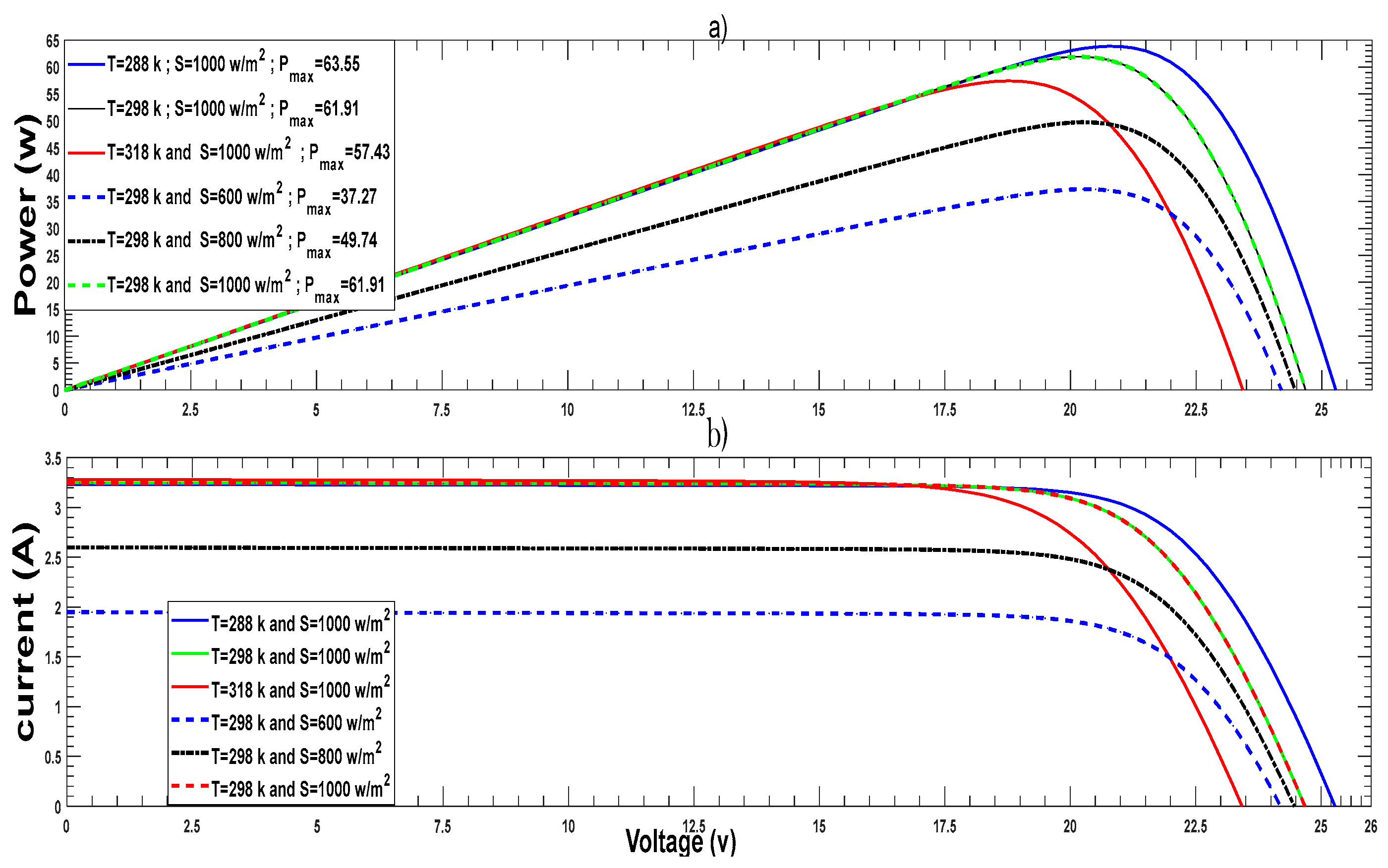
| Maximum PV-module power (Pmax) | ≈61.92 W |
| Open circuit PV-module voltage (voc) | 25.25 V |
| PV-module short circuit current (isc) | 3.25 A |
| PV-module voltage at maximum power (vmpp) | 20 V |
| PV-module current at maximum power (impp) | ≈3.1 A |
| factor of ideality n1 | 1 |
| factor of ideality n2 | 2 |
| Number of PV-cells connected in series (Ns) | 36 |
| Number of PV-cells connected in parallel (Np) | 1 |
| Classical One Stage IC Algorithm with δα = 5 × 10⁻⁴ | Classical One Stage IC Algorithm with δα = 1 × 10⁻⁴ | Hybrid IC-LQI Algorithm | |
|---|---|---|---|
| Scenario 1 | 89.4% | 65.57% | 98.05% |
| Scenario 2 | 95.82% | 91.3% | 98.24% |
| Scenario 3 | 96.10% | 87.75% | 98.92% |
Disclaimer/Publisher’s Note: The statements, opinions and data contained in all publications are solely those of the individual author(s) and contributor(s) and not of MDPI and/or the editor(s). MDPI and/or the editor(s) disclaim responsibility for any injury to people or property resulting from any ideas, methods, instructions or products referred to in the content. |
© 2023 by the authors. Licensee MDPI, Basel, Switzerland. This article is an open access article distributed under the terms and conditions of the Creative Commons Attribution (CC BY) license (https://creativecommons.org/licenses/by/4.0/).
Share and Cite
Bouarroudj, N.; Houam, Y.; Djari, A.; Feliu-Batlle, V.; Lakhdari, A.; Benlahbib, B. A Linear Quadratic Integral Controller for PV-Module Voltage Regulation for the Purpose of Enhancing the Classical Incremental Conductance Algorithm. Energies 2023, 16, 4532. https://doi.org/10.3390/en16114532
Bouarroudj N, Houam Y, Djari A, Feliu-Batlle V, Lakhdari A, Benlahbib B. A Linear Quadratic Integral Controller for PV-Module Voltage Regulation for the Purpose of Enhancing the Classical Incremental Conductance Algorithm. Energies. 2023; 16(11):4532. https://doi.org/10.3390/en16114532
Chicago/Turabian StyleBouarroudj, Noureddine, Yehya Houam, Abdelhamid Djari, Vicente Feliu-Batlle, Abdelkader Lakhdari, and Boualam Benlahbib. 2023. "A Linear Quadratic Integral Controller for PV-Module Voltage Regulation for the Purpose of Enhancing the Classical Incremental Conductance Algorithm" Energies 16, no. 11: 4532. https://doi.org/10.3390/en16114532