Review

Flexible Solid-State Lithium-Ion Batteries: Materials and Structures

College of Mechanical and Electrical Engineering, Qingdao University, Qingdao 266071, China
*
Author to whom correspondence should be addressed.
Energies 2023, 16(12), 4549; https://doi.org/10.3390/en16124549
Submission received: 21 March 2023 / Revised: 8 May 2023 / Accepted: 29 May 2023 / Published: 6 June 2023
(This article belongs to the Section D2: Electrochem: Batteries, Fuel Cells, Capacitors)

Abstract

:
With the rapid development of research into flexible electronics and wearable electronics in recent years, there has been an increasing demand for flexible power supplies, which in turn has led to a boom in research into flexible solid-state lithium-ion batteries. The ideal flexible solid-state lithium-ion battery needs to have not only a high energy density, but also good mechanical properties. We have taken a systematic and comprehensive overview of our work in two main areas: flexible materials and flexible structures. Specifically, we first discuss materials for electrodes (carbon nanotubes, graphite, carbon fibers, carbon cloth, and conducting polymers) and flexible solid materials for electrolytes. A discussion of the structural design of flexible solid-state lithium-ion batteries, including one-dimensional fibrous, two-dimensional thin-film and three-dimensional flexible lithium-ion batteries, follows this. In addition, the advantages and disadvantages of different materials and structures are summarized, and the main challenges for the future design of flexible solid-state lithium-ion batteries are pointed out, hopefully providing some reference for the research of flexible solid-state lithium-ion batteries.

1. Introduction

In recent years, flexible/wearable electronics have received enthusiastic attention from academia and industry for their increasingly widespread applications. Flexible electronic devices currently include flexible electronic displays [1], electronic skin [2], electronic paper [3], flexible conductive fabrics [4], smart clothing [5], wearable monitoring devices [6], flexible phones [7], flexible circuits [8], etc. However, traditional batteries cannot meet the needs of current flexible electronic devices due to the limitations of their materials, structure, size and shape. Therefore, the design and development of power supplies with excellent flexibility, variable length, and excellent and stable electrochemical properties to meet the needs of a wide range of flexible and wearable electronic devices have become one of the most critical issues governing flexible electronics. Therefore, developing and researching flexible energy storage devices will become essential for developing flexible electronics.
Lithium-ion batteries account for the vast majority of power supplies for electronic products. Compared to other energy storage systems, the development of lithium-ion batteries is more mature. Therefore, flexible lithium-ion batteries are the most likely flexible energy system to be used first. At present, the industry has put forward higher challenges for the bendability of flexible lithium batteries: the target bending radius of flexible lithium batteries for wristbands adapted to smart watches is at least 20 mm; the radius of bending of flexible lithium batteries for flexible mobile phones is at least 30 mm; foldable mobile phones even require the radius of bending of flexible lithium batteries to 3 mm [9]. However, current processes such as coating and assembly of lithium-ion batteries and the materials were chosen to determine the non-bendability and non-variable size and shape of conventional lithium-ion batteries, as the bending process can cause the electrode active material to detach from the collector fluid and affect the battery performance and may even puncture the diaphragm and leak the electrolyte leading to short circuits. Solid-state batteries have received much attention for next-generation energy storage devices due to their potential to achieve higher energy density and superior safety performance compared to current lithium-ion batteries [10]. Therefore, the development of thin, light, and flexible solid-state Li-ion batteries has become a hot research topic in the field of Li-ion batteries [11]. At the same time, if flexible lithium batteries are industrialized on a large scale as energy supply devices, their energy density cannot be lower than that of conventional lithium batteries (200 Wh/kg) [12]. As with traditional rigid Li-ion batteries, electrodes play a crucial role in the battery’s capacity, energy density, and power density. Choosing electrode materials and cell structure is the key to achieving a high-performance flexible battery. Among numerous studies, flexible lithium-ion batteries have demonstrated excellent mechanical properties compared to traditional lithium-ion batteries (Table 1).
This paper reviews the materials used for the various components of flexible solid-state lithium-ion batteries (electrodes and electrolytes) and the structural design of the batteries. The advantages and disadvantages of the prepared flexible electrodes and electrolytes in terms of electrical performance (energy density and multiplicative performance) and mechanical performance (failure under cyclic deformation conditions) are discussed and summarized, respectively. Hopefully, this review will provide a reference for developing flexible solid-state lithium-ion batteries.
We will then describe the materials used in flexible solid-state lithium-ion batteries in Section 2. In Section 3, we describe the structure of flexible solid-state lithium-ion batteries. Section 4 concludes the text and presents the following challenges for flexible solid-state lithium-ion batteries.

2. Materials for Flexible Solid-State Lithium-Ion Batteries

To meet the demands of flexible electronics, flexible lithium-ion batteries require all critical components (collector, active layer, diaphragm, and packaging) to be bendable and even foldable. To meet the needs of flexible electronics, flexible lithium-ion batteries require all critical components (collector, active layer, diaphragm, and packaging) to be bendable and even foldable.

2.1. Flexible Electrode Materials

Research on flexible electrode materials that can be applied to wearable devices has focused on stretchable fabrics with bending radii less than 30 mm and tensile strains more significant than 5% to meet the requirements of the PC−2292 standard [13]. Electrode materials should also have a low resistance to improve charge transfer efficiency [14]. Materials that meet both requirements include carbon nanotubes, graphene, and carbon fibers (cloth). Therefore, we classify the following discussion according to the different electrode materials.

2.1.1. Carbon Nanotube

Carbon nanotubes (CNTs) have unique mechanical and electrical properties as one-dimensional nanomaterials due to their nanoscale dimensions and quantum effects [15,16,17]. However, pure carbon nanotubes have a low coulombic efficiency [12] and cannot be used as electrodes independently. Introducing an active substance into the carbon material can increase the active reaction sites, and the electrode capacity or multiplicative performance can be improved [18,19,20].
Carbon is the traditional anode for lithium-ion batteries, but previous anodes made of carbon have been detrimental to battery capacity and challenging to achieve flexibility [21]. Exciting work has been published in the search for new materials for battery anodes. Yan et al. [22] investigated cobaltous sulfide, a novel material for lithium-ion batteries. Many different molybdenum disulphide (MoS 2 ) nanostructures have also been reported as anode materials for lithium-ion batteries (LIBs) [23,24,25]. Although such materials have a greater discharge capacity than pure carbon materials, the compound MoS 2 , which has a chalcogenide structure, has poor cycling properties. Doping CNT can improve the cycling performance of MoS 2 . For example, Ding et al. [26] reported a simple glucose-assisted hydrothermal way to grow MoS 2 nanosheets (NSs) directly on carbon nanotube backbones. The MoS 2 content in the hybrid structure is significantly increased due to the shell layer consisting of lamellar substituents. At the same time, the large surface area provided by this unique layered structure may help to store more lithium, while the void space between these lamellar subunits can buffer the volume change during charging and discharging, thus improving the retention of cyclic capacity. In addition, the glucose-derived carbon ensures good contact between the carbon nanotube backbone and the shell layer of MoS 2 NSs and forms an excellent conductive network. Compared to pure MoS 2 flakes, these CNT@MoS 2 NSs nanocomposites exhibit enhanced lithium storage performance with better cyclic capacity retention and higher reversibility.
In addition to MoS 2 , Fe 3 O 4 can also be used as an active substance in the electrode to coordinate with CNT use. Ban et al. [27] used the unique properties of highly crystalline and long single-walled carbon nanotubes (SWCNTs) [28] to synthesize Fe 3 O 4 nanoparticles uniformly embedded in an interconnected SWCNT network in a simple two-step process. In addition, no polymer binder is required to maintain electrical conductivity. The energy density of the electrode can be increased by increasing the amount of active material in the CNT composite electrode. The electrodes contain 95 wt% active material and only five wt% SWCNT as a conductive additive (a typical electrode contains 80 wt% active material and 20 wt% conductive additive and binder additive). The result is a high reversible capacity of 1000 mAh/g and a high multiplier capacity and stable capacity of 800 mAh/g at 5 C (over 100 charge/discharge cycles). The power of the electrodes was effectively increased by reducing the use of binders.
The above provides an overview of the applications and evolution of CNTs in anodes. In the cathode of a rigid Li-ion battery, CNT is often used to enhance electron transfer and increase the contact surface area of the active material. In the cathode of a flexible Li-ion battery, the electrode is usually made more flexible by using a polymer substrate [29]. The combination of CNT and active materials also requires the use of adhesives. Zhang et al. [30] studied a flexible lithium-ion battery based on LFP/CNT/EVA and LTO/CNT/EVA on the basis of a LiFePO 4 (LFP) polymer battery. This work used an ethylene vinyl acetate copolymer (EVA) as an electrode binder, adjustable support, and ion channel. Typical commercial electrode materials LiFePO 4 (LFP) and Li 4 Ti 5 O 12 (LTO) were chosen as the active materials for the electrodes, and CNT was chosen as the conductive material in the electrodes. The EVA chains and CNT wrapped around the active material to form a homogeneous ternary structure with a mass content of 80 wt% of active material. A capacity of 120 mAh/g can be achieved. After reaching full charge, the LFP//LTO battery exhibits an ultra-stable operating voltage of 1.86 V in a flat bending state for an extended period (Figure 1a), which means that the LFP//LTO battery can provide a stable operating voltage for other electronic devices. The red LED can be illuminated by the LFP//LTO battery and remains bright in various bending states (Figure 1b,c). In addition, three flexible full cells can be connected in series to charge smartphones. The flexible full cells work correctly even when bent to a large angle (Figure 1d).
The above studies found that adding binders to enhance the electrodes’ mechanical properties and deformability reduced active substance content and poor cycling performance. To solve these problems, Kamran Amin et al. [31] synthesized a sulfur-linked carbonyl-based poly (2,5-dihydroxyl-1,4-benzoquinonyl sulfide) (PDHBQS) compound and used it as a cathode material for LIBs. Flexible binder-free composite cathodes with single-walled carbon nanotubes (PDHBQS-SWCNTs) were fabricated by vacuum filtration. Electrochemical measurements showed that the PDHBQS-SWCNTs anode could provide a discharge capacity of 182 mAh/g (0.9 mAh/cm 2 ) at a current rate of 50 mA/g, and its potential window is 1.5–3.5 V. The positive electrode provides a capacity of 75 mAh/g (0.47 mAh/cm 2 ) at 5000 mA/g, which confirms its good multiplicative performance at high current densities. The PDHBQS-SWCNTs flexible cathode retains 89% of its initial capacity after 500 charge/discharge cycles at 250 mA/g. In addition, large area (28 cm 2 ) flexible cells based on PDHBQS-SWCNT cathodes and lithium foil cathodes were also assembled. The flexible cells showed good electrochemical activity during continuous bending, retaining 88% of their initial discharge capacity after 2000 bending cycles. The bending radius is 2.1 mm.
It should be emphasized that carbon nanotubes have applications in rigid batteries. In flexible batteries, in addition to enhancing electron transfer and increasing surface area, the inherent flexibility of carbon nanotubes also plays a role [32,33]. In addition, doping carbon nanotubes with active materials is another standard method to improve the performance of flexible electrodes [26,27,28,29,30,31,32,33,34]. However, there are some challenges in using carbon nanotubes in flexible electrodes: (1) Although individual CNTs exhibit good mechanical strength and conductivity, the overall performance of electrodes composed of CNTs is usually unsatisfactory due to the contact resistance between particles. Introducing metal nanoparticles to form cross-linkages is one way to reduce contact resistance and should be added appropriately to avoid hardening of the material and loss of flexibility. (2) The electrode composite materials of carbon nanotubes usually require adhesives to maintain the stability of the carbon nanotube network, which inevitably reduces the energy density of the battery. These issues can be further improved by reducing the proportion of adhesive or not using an adhesive. However, binder-free solutions can also make the electrodes less flexible.

2.1.2. Graphene

Graphene has excellent mechanical properties due to its two-dimensional structure and can maintain high electrochemical performance during bending deformation [35,36]. Although the addition of graphene reduces the extensibility of composite materials [37], graphene is still widely used in various batteries [38,39,40,41], including lithium-ion batteries.
Reduced graphene oxide (RGO) has a large specific surface area due to its internal structure. Wang et al. [42] fabricated a highly flexible, conductive, robust, and self-contained RGO/Co 9 S 8 nanocomposite paper by a simple combination of high-energy ball milling and vacuum filtration (Figure 2a). This composite paper can be used directly as a stand-alone anode for flexible Li-ion batteries without adhesives, conductive agents, and metal collectors. This electrode has a high specific capacity of 1415 mAh/g, and after 500 cycles at a current density of 545 mA/g, the specific capacity can reach 573 mAh/g. The introduction of RGO improves the rate capability of the electrode. The large specific surface area of reduced graphene oxide results in a uniform distribution of Co 9 S 8 , which better accommodates the volume expansion/shrinkage of Co 9 S 8 during repeated charge/discharge cycles. However, the surface integrity of graphene is destroyed during reduction-oxidation, and the mechanical properties are reduced. So, increasing the surface area of graphene in electrodes without reduction-oxidation becomes the main research problem.
The use of graphene in electrodes is beneficial for the advancement of negative electrode materials. Silicon (Si) has a much higher theoretical capacity than Co 9 S 8 . However, the volume change (400%) and low conductivity of Si during cycling adversely affect its cycle life and rate performance. Han et al. [44] grew vertical graphene sheets (VGSs) on Si particles through thermochemical vapor deposition to form a flexible, porous surface layer. The surface area of graphene was increased without reductive oxidation while solving the problem of significant volume expansion of Si. VGSs encapsulated Si particles (VGSs/Si) have low volume distortion (12.9% thickness after 100 cycles) and a high lithium-ion diffusion coefficient (1.5 × 10 12 –4.4 × 10 9 cm 2 /s) due to the good VGSs flexibility, high porosity, and excellent electrical conductivity. As a LIB anode, the VGSs@Si nanocomposite has a high reversible capacity of 2696.1 mAh/g, a long cycle life (500 cycles, 80.1% capacity retention at 2 A/g), and an excellent rate capability (457.9 mAh/g at 20 A/g). It can be seen from this work that the addition of graphene effectively solves the volume expansion problem of silicon negative electrodes, greatly improving the cycling performance and safety of silicon negative electrodes.
The improvement effect of graphene material on current and ion transfer efficiency is also reflected in the cathode material. Gao et al. [45] prepared an active cotton fabric (ACT) with porous tubular fibers embedded in NiS nanobowls and encapsulated with conductive graphene sheets (ACT/NiS-graphene) by a simple two-step heat treatment method. The composite exhibits excellent electrochemical performance, including ultra-high initial discharge capacity (1710 mAh/g at 0.01 C), excellent doubling performance (discharge capacity maintained at 645 mAh/g after 100 cycles at 1 C), and excellent cycling stability (discharge capacity recovered after 400 cycles at 0.1 C to 1016 mAh/g).
Graphene is universal in improving cathode materials. Among them are lithium sulfur batteries with volume expansion and “shuttle effect” [46,47,48]. In various studies on nanostructured carbon materials [49,50,51], it has been found that the large specific surface area of graphite materials can effectively compensate for the shortcomings of lithium sulfur batteries. Graphene can increase the active surface area of the sulfur positive electrode in lithium-sulfur batteries, reduce the volume expansion after lithiation of sulfur, and suppress the “shuttle effect” in lithium-sulfur batteries.
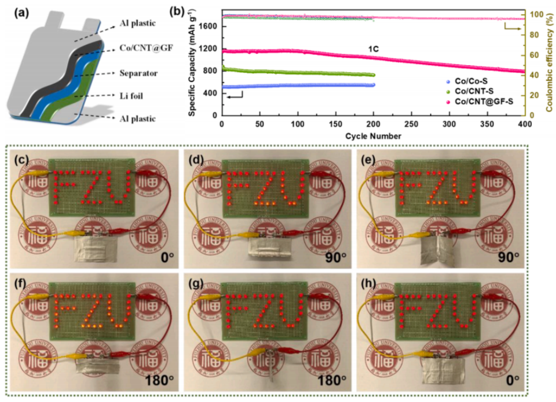
Xie et al. [43] successfully developed an N-doped interconnected carbon nanotube (CNT) and metallic cobalt particles with an inner layer covered with graphene nanoflowers (GF) and an outer layer of carbon cloth (CC) as a solution method combined with chemical vapor deposition (CVD) and plasma-enhanced chemical vapor deposition (PECVD) techniques to obtain a unique bilayer carbon structured self-supported flexible sulfur body (Co/CNT@GF) (Figure 2b). Fill the Li 2 S 6 cathode liquid as an active substance into the above structure to form the cathode together. The external micrometer-thick GF packaging layer can be successfully penetrated by the Li 2 S 6 cathode and enter the “dry loofah” skeleton structure of Co/CNT, and the GF packaging layer will not be damaged during this process, reflecting its own stability. Compared with cathodes without GF components, cathodes with GF components have a greater current response, indicating that micrometer-thick GF packaging layers can effectively inhibit sulfur loss into the electrolyte and maintain high sulfur utilization in redox reactions and the cathode containing GF also has better electrochemical reversibility. The addition of GF also effectively reduces the charge transfer resistance of the cathode, which is more conducive to electron transfer. In the long-term cycling performance test, the initial discharge capacity of the cathode with GF added under 1 C conditions was 1155 mAh/g, and the specific discharge capacity remained at 793 mAh/g after 400 cycles, with an average Coulombic efficiency of 97.6%. In addition, when the current density increases to 2 C, Co/ CNT@GF-S cathode also exhibits a high discharge capacity of 793 mAh/g, indicating that the cathode with GF addition has a higher specific discharge capacity and superior long-term cycling performance even under high magnification conditions (Figure 3b). Assemble the cathode with GF into a bag battery (Figure 3a, and connect the LED lamp to the bag battery for bending testing (Figure 3c–h). With horizontal and vertical bending at 90 , 180 , and finally, back to the initial state, the LED light could operate properly throughout, making the flexible Co/CNT@GF-S promising for wearable and portable electronic device applications.
Graphene is a material with a two-dimensional monolayer structure. Transition metal carbides and nitrides (MXenes) are another class of two-dimensional inorganic compounds with high electrical conductivity, high ion mobility, good mechanical strength, and large surface functional groups [52]. The application of Mxenes in energy conversion and storage systems has been demonstrated experimentally and theoretically [53]. The application of MXenes in flexible batteries has also been shown to be a promising direction [54,55,56]. However, their high manufacturing cost hinders the application of industrialization and impedes the application of automation. Moreover, the problem of poor tensile properties for graphene still needs to be solved. The application of graphene in flexible lithium-ion batteries still faces many challenges.

2.1.3. Carbon Fiber/Carbon Fiber Cloth

Carbon fiber (CF) is a wire-like material composed of carbon atoms with diameters between 5 and 10 μ m [57]. The diameter of carbon fibers is much larger than that of carbon nanotubes, so the surface area, as well as the bending ability of carbon fibers, is less than that of carbon nanotubes. However, carbon fibers have high elastic modulus, lithium-ion embedding capability, and a more straightforward production process. The price advantage makes carbon fiber more favorable for industrializing flexible lithium-ion batteries.
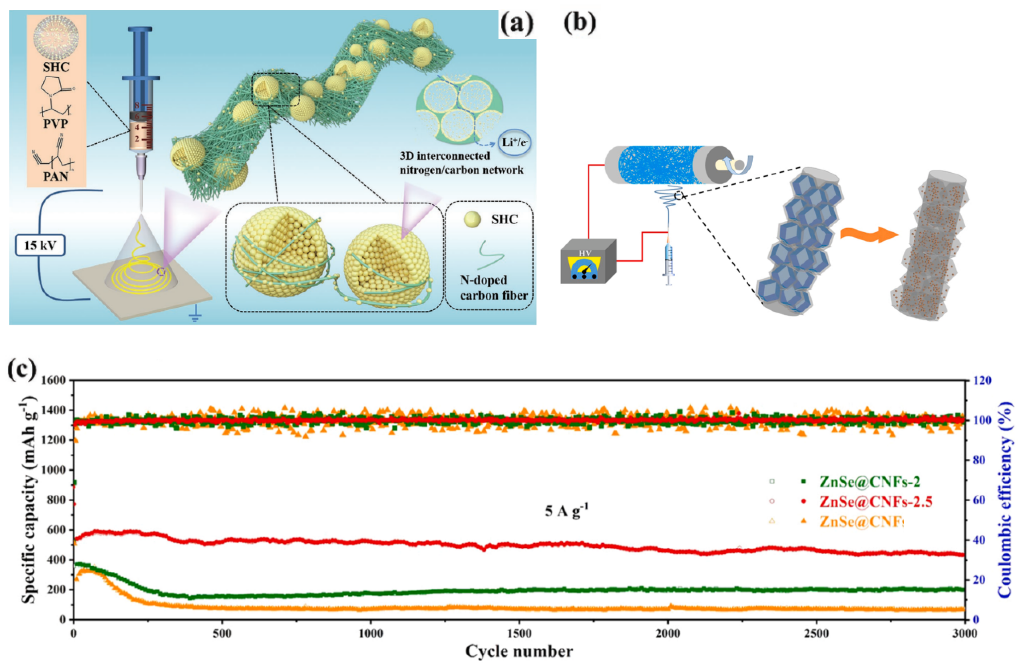
Studies have shown that carbon fibers can reversibly embed lithium ions with a capacity of 350 mAh/g, comparable to graphite (372 mAh/g ) [58]. In addition, the conductivity of carbon fibers can reach about 1000 S/cm, which allows them to be used without a collector. Removing collectors and additives from the overall structure and introducing carbon fibers into the LIBs reduces the inactive mass and provides mechanical stability. Generally, the manufactured carbon fibers are less reactive, so the carbon fibers require a reactive material coating that adheres well to the carbon fibers. Obtaining a uniformly distributed layer of active material particles can affect the mechanical properties of the structural cell. Excessive functional material coating decreases the fiber volume fraction in the structured cell and will reduce its mechanical properties but will increase the energy density.To solve this class of problems, different fabrication methods are needed. The electrostatic spinning method is one of the most widely used in the laboratory. Zhang et al. [59] prepared flexible carbon nanofiber membranes with uniformly distributed molybdenum dioxide (MoO 2 ) nanocrystals using a needle-free electrospinning method combined with a subsequent carbonization process, which exhibited excellent structural stability underwear and deformation conditions. The lithium-ion battery prepared using MoO 2 //C nanofiber membranes as a self-supporting anode had a discharge capacity of up to 450 mAh/g after 500 cycles at 2000 mA/g. In addition, the structure of the nanofibers remained unchanged after 500 cycles, which reflected the excellent stability of the material. Zhu et al. [60] used self-assembled carbon fiber microspheres and interwoven fabrics to prepare a binder-free self-supporting anode electrode paper in which a three-dimensional interconnected nitrogen/carbon network connected hollow carbon nanospheres with uniformly distributed silicon nanodots (Figure 4a). The reversible capacity of the prepared anode is 1442 mAh/g after 800 cycles at 1A/g in lithium half batteries and 450 mAh/g after 200 cycles at 0.5A/g in full lithium batteries, respectively. Additionally, using an electrostatic spinning technique but with ZnSe as the active material, Zhang et al. [61] prepared ZnSe@carbon nanofibers (ZnSe@CNFs) with plasticity and flexibility (Figure 4b). Due to the structural advantage of ZnSe nanoparticles encapsulated in the conductive network of carbon nanofibers, the electrode has excellent electrochemical properties, including excellent multiplicative performance and ultra-long cycle life (426.1 mA/g for 3000 cycles at 5 A/g (Figure 4c) with only 0.01% decay per cycle). More importantly, the self-supporting electrodes can be further applied to pouch cells with an excellent capacity of 448.9 mAh/g in 700 cycles at 0.5A/g. Even after 30 repetitions of folding at different angles (90 , 180 and 0 ), the pouch cell remains in the same original state and lights up the LED (Figure 5a–e). Carbon fibers are also used in lithium-sulfur batteries to address sulfide swelling and shuttle effects. Li et al. [62] used a simple simultaneous activation/pyrolysis process and effectively adjusted the potassium bicarbonate activator to prepare ordinary cosmetic cotton into self-supporting porous carbon fibers (SPCFs) (Figure 5f). The prepared SPCF materials have an interconnected porous backbone with an ultra-high specific surface area of 2124.9 m 2 /g and a large pore volume of 1.01 cm 3 /g while exhibiting muscular flexibility. The SPCF-based sulfur cathode shows a high coulombic efficiency of about 99%. A reversible capacity of 450 mAh/g can be obtained after 300 cycles at a high current multiplicity of 0.5 C.
There is another class of materials called carbon fiber cloth (CFC) or carbon cloth (CC), and they are obtained by the carbonization of textiles [63]. Similar to carbon fiber, CFC and CC are also used to enhance electrodes’ charging and discharging capacity by adding active materials [64,65]. Wang et al. [66] fabricated adhesive-free composite electrodes (LTO@CFC) for flexible Li-ion batteries by growing arrays of active material spinel lithium titanate (LTO) orthorhombic on flexible carbon fiber cloth (CFC) (Figure 6a). LTO@CFC electrodes exhibit very high multiplicative performance, with a capacity of 105.8 mAh/g at 50 C and excellent cycling electrochemical stability (only 2.2% capacity loss after 1000 cycles at 10 C). The LED bulb can still be lit after bending 200 times (Figure 6b–d). Carbon cloth (CC) has also been used in anodes. Dylan Storan et al. [67] grew silicon nanowires on high-density carbon cloth for use as anodes in Li-ion batteries. The nanowires were produced using a modified vapor growth process. The electrodes have a high area charge/discharge capacity and long-term cycling stability.
Carbon fibers and carbon cloth are suitable substrates for electrodes because they are very flexible and self-supporting, reducing the use of metal collectors and adhesives. The flexibility and self-supporting properties of CF and CFC(CC) allow the electrode to try more active substances. On the one hand, introducing active substance nanomaterials into micron-sized carbon fibers results in a multi-layered microporous structure, which will increase the specific surface area of the material. On the other hand, the nanostructure can shorten the ion diffusion channels and accelerate the exchange of electrons and ions in the electrode reaction. With the effect of these two aspects, the energy rate and rate capability of flexible Li-ion batteries gains increased. However, the active nanoparticles are uniform on the surface of carbon fiber and the amount of active material affects the mechanical properties of the carbon substrate. In addition, smaller nanoparticles have larger surface energy, which can lead to agglomeration. This agglomeration weakens the long-term stability of the electrode. Therefore, controlling the stability of nanostructured carbon fibers poses certain challenges.

2.1.4. Conductive Polymers

The main chain of conductive polymer materials has a conjugated main electron system, and the conductivity can reach over 1000S/cm by doping other materials. For example, heteroatom-free polyacetylene (PAC), polyaniline (PANI), N-heteroatom-containing polypyrrole(PPy), poly (3,4-ethylenedioxythiophene) (PEDOT), and poly (3,4-ethylenedioxythiophene) polystyrene sulfonate (PEDOT: PSS) with certain conductivity and flexibility have been proved to be able to be used as flexible electronic materials [68,69,70,71,72].
Polypyrrole is a heterocyclic conjugated conductive polymer widely studied and used, with a conductivity of 100–1000 S/cm, a tensile strength of 50–100 MPa, and good electrochemical oxidation-reduction reversibility. Polypyrrole is usually used in electrodes together with active substances. Replacing the self-weighting conductive carbon and binder in the original electrode with a conductive polymer can improve the capacity of lithium-ion batteries at high charging multipliers. However, integrating polypyrrole and metals (metal oxides) on a single electrode is particularly challenging. This is because the electrodeposition of polypyrrole (PPy) and metal (or metal oxide) typically requires opposite potentials. Li et al. [73] successfully prepared PPy and metal oxide nanocomposites on the cathode by a one-step method. It gives a feasible way for the application of PPy on electrodes. Huang et al. [29] prepared LiFePO 4 /polymer composite cathodes using polypyrrole (PPy) and polyaniline (PANI) as conducting polymers by both chemical deposition and simultaneous chemical polymerization. This shows that polyaniline (PANI) can also be used in electrodes. Liao et al. [74] prepared SiOx-G/PAA-PANI/graphene composites using in situ polymerization, where SiOx-G particles were linked together by a graphene-doped polyacrylic acid-polyaniline conductive flexible hydrogel and SiOx-G was encapsulated in a conductive hydrogel (Figure 7). The results show that the SiOx-G/PAA-PANI/graphene composite has a discharge-specific capacity of 842.3 mAh/g, a current density of 500 mA/g, and an initial coulombic efficiency of 74.77% after 100 cycles. This excellent performance may be attributed to the three-dimensional (3D) structure of the conducting polymer hydrogel that improves lithium-ion transmission and conductivity.
In silicon anode, conducting polymers can also be used to improve the rate performance of the electrode instead of partial binders. Tang et al. [75] designed a ternary polymer consisting of poly (vinyl alcohol), poly(dopamine hydrochloride), and poly(3,4-ethylenedioxythiophene)/poly(styrene sulfonate) and the binder is used in silicon anodes. The composite exhibits elongation up to 243.7% and has excellent bending and twisting ability, which helps to buffer the significant volume change of the silicon anode during cycling. The poly(3,4-ethylenedioxythiophene)/poly(styrene sulfonate) (PEDOT:PSS) in this binder improves the multiplicative performance.
Conductive polymers can be used in flexible electrodes, but applying conductive polymers in flexible lithium-ion batteries is still challenging. On the one hand, conductive polymers have very low conductivity and often must be combined with other conductive media. On the other hand, the different polymer mechanisms and synthesis conditions lead to the transfer of polymer products, making it more difficult to maintain continuous production. Currently, conductive polymers are still more often used to improve the collector as well as the binder part of the electrode.

2.1.5. Challenges and Summary of Flexible Electrodes

In the above, we described the applications of materials such as CNT, graphene, CF, and conductive polymers in flexible electrodes (Table 2). CNTs are considered excellent electrode materials because of their high electrical conductivity and flexibility as one-dimensional materials. However, applying CNTs in electrodes often requires a binder, a feature that reduces the active material mass ratio of the electrode, and the high manufacturing cost of CNTs also restricts the use of CNTs as electrodes. Therefore, CNTs are often used as performance-enhancing materials in electrodes rather than as electrodes. Two-dimensional materials (graphene/Mxene) have high electrical conductivity and good ion mobility. However, they are also costly to produce. The internal structure of CF and CFC makes them excellent electrode substrates, reducing the use of binders and collectors. Adding active substances to them increases the energy density, and adding CNTs or graphene increases the conductivity of the electrode. The required properties of the electrodes can be refined by adjusting the ratio of active substances to conductive nanomaterials. Conductive polymers, such as CF and CFC, can replace the binder and collector in the electrode. However, conductive polymers do not have the internal structure of CF and CFC. This results in the low ionic conductivity of conductive polymers. However, conductive polymers have a more significant potential for deformation.
Faced with different mechanical performance requirements, different electrode materials can be selected to meet them. If the electrode needs to meet more application scenarios (bending, folding, and twisting), carbon nanotubes or conductive polymers need to be selected as the electrode material. If the application scenario of the electrode does not involve stretching, graphene or carbon fiber can be selected as the electrode material. If the electrode has low requirements for the bending radius and no requirements for stretching, carbon cloth can be selected as the electrode material.
The selection of electrode materials cannot be solely based on mechanical properties. While meeting the mechanical performance, we also need to strive to meet the electrochemical performance as much as possible. For example, electrodes containing carbon nanotubes and electrodes containing conductive polymers that can simultaneously meet various deformation scenarios can accommodate more active substances and have better conductivity than the latter. So, the former has better specific capacity and rate performance than the latter, but the latter has better elongation than the former. Carbon nanotubes are often the best choice for electrode materials without the need for extreme stretching.
In summary, CFC and CF are the most economical materials for flexible electrodes. One-dimensional and two-dimensional carbon nanomaterials have stronger electrochemical and mechanical properties compared to the former, but two-dimensional carbon nanomaterials have shortcomings in tensile properties. Conductive polymers can accommodate more deformation among them. Although the conductivity of conductive polymers is low at this stage, as more components are tried, conductive polymers are still considered the most promising materials for composing flexible electrodes.

2.2. Flexible Electrolyte Materials

Most application scenarios for flexible lithium-ion batteries (FLIBs) are in flexible electronics, so FLIBs need to be bent many times in their lifetime. This gives the classical lithium-ion battery with liquid as an electrolyte a significant safety issue. Bending increases the risk of electrolyte leakage and further combustion. So, replacing the liquid electrolyte with a solid (or gel) electrolyte becomes viable. Solid electrolytes can be divided into two broad categories, solid polymer electrolytes (SPEs) and inorganic solid electrolytes (crystals, glass, ceramics, etc.) [76,77,78,79,80,81]. SPEs are more suitable for application in FLIBs due to their soft and flexible properties, low manufacturing cost, tunable chemical structure, and good electrode/electrolyte interface formation [82,83,84,85]. Manjit et al. [86] prepared cross-linked network polymer electrolyte membranes by a single-pot facile in situ thiol-ene polymerization method, which consisted of poly(ethylene glycol)-diacrylate and methacrylate-terminated polydimethylsiloxane (PDMS). This polymer electrolyte membrane has a tensile strength in the range of 2.07 to 2.74 MPa, Young’s modulus in the field of 8.28 to 11.68 MPa, and strain at break in the range of 24.42 to 37.90%. It is capable of arbitrary bending and folding and shows an excellent ionic conductivity of 1.30 × 10 4 S/cm at 60 C.
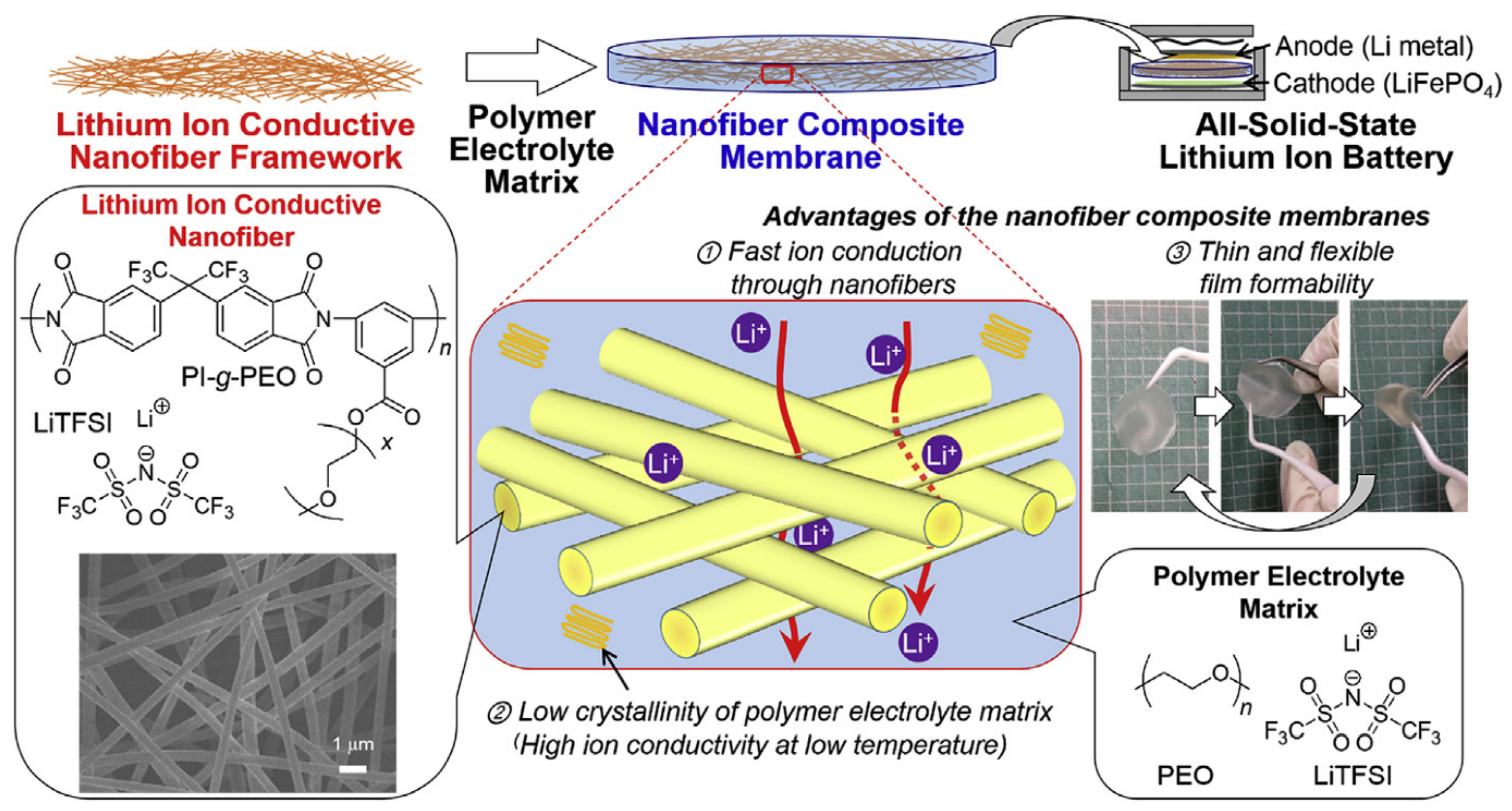
Poly (ethylene oxide) (PEO) is uniquely attractive among the many polymeric materials. This is because of its excellent solubility for Li-ion [87]. However, PEO films are usually too thick to avoid the risk of severe short circuits due to their poor mechanical strength. Tsukasa et al. [88] proposed a new structural design of composite SPE consisting of a lithium-ion conducting nanofiber backbone and a polymer electrolyte matrix PEO containing lithium salts (Figure 8). In this study, the nanofibers were used not only as a backbone to improve the mechanical properties of PEO, but also as a lithium-ion conducting material to improve the ionic conductivity of the polymer electrolyte matrix by reducing the crystallinity of PEO. This composite solid polymer electrolyte has good mechanical stability, good ionic conductivity (10 4 S/cm at room temperature), lithium-ion mobility number (0.5), good charge/discharge cycle behavior, and moderate multiplicity performance of the battery. In the above two research works, we also found that the ionic conductivity of PEO-based electrolytes increases at elevated temperatures. However, the PEO loses its mechanical strength when it becomes molten at too high a temperature.
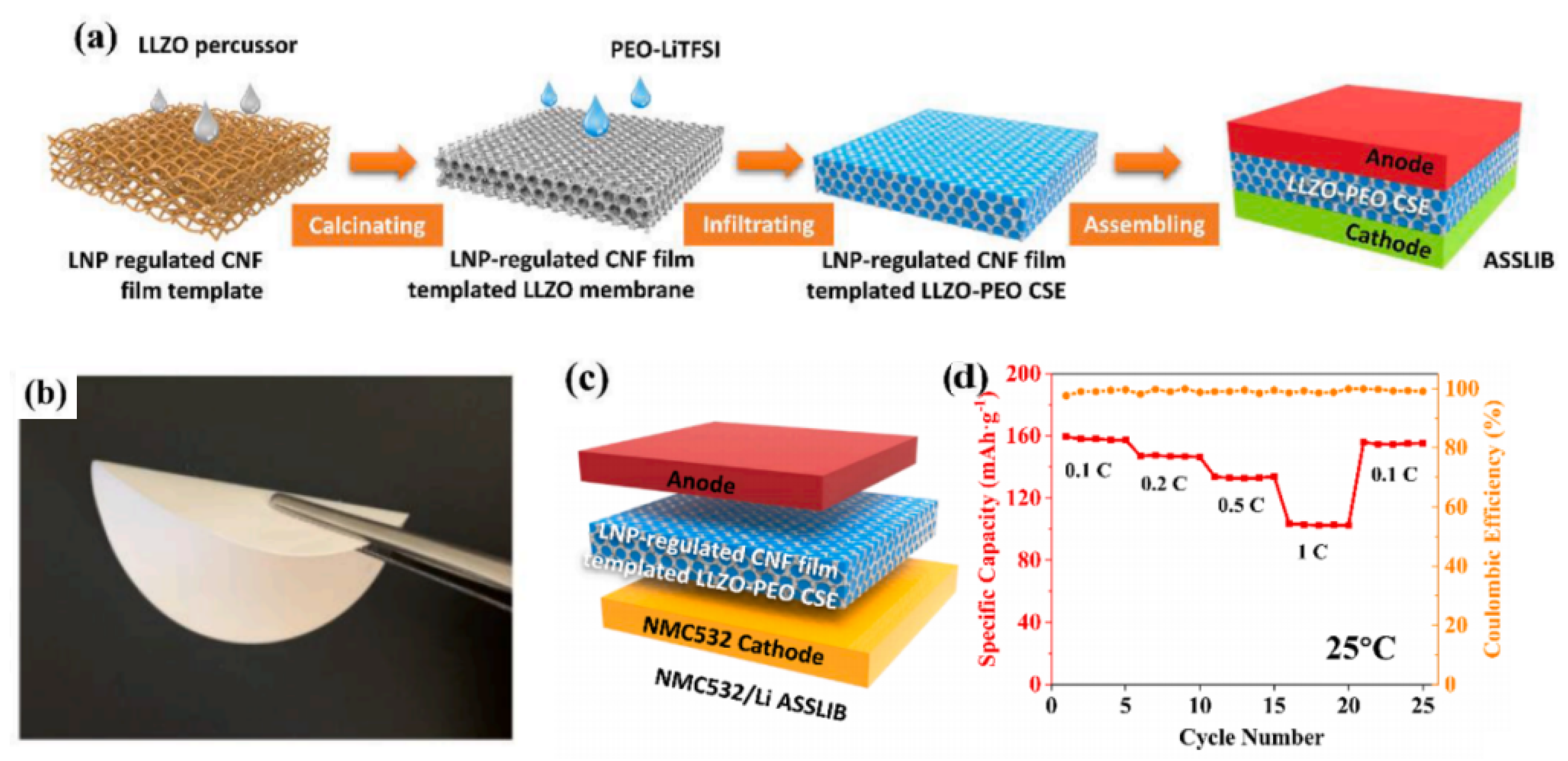
Lithium-ion migration channels are also an issue to be considered when designing SPEs, which often require high ionic conductivity. However, the high concentration of ceramic fillers in some SPEs leads to aggregation, which hinders the ionic conductivity of SPEs [88,89,90]. The pre-design of ordered and controllable templates with regular sizes and shapes used to limit the aggregation of inorganic fillers has proven to be a practical and innovative approach [91,92]. Zhang et al. [93] developed thin, flexible, and conductive SPEs by using lignin nanoparticles (LNPs) to modulate the pore properties of cellulose nanofibril (CNF) film templates. CNF-LNP films were first prepared, and then the LNPs were removed. The CNF films with uniform porosity were formed and used to prepare Li 7 La 3 Zr 2 O 12 (LLZO) films with good morphological structure (pore size, uniformity) (Figure 9a). PEO was then permeated into the films to produce thin, flexible, and conductive SPEs (Figure 9b). The LLZO film has a controlled interconnected structure and is compatible with PEO. The prepared SPE exhibits a high lithium-ion conductivity of 1.83 × 10 4 S/cm at room temperature. The continuous and uniform lithium transfer path and the excellent electrolyte/electrode interface contact contribute to the long-term cycling stability of the symmetric lithium battery. Therefore, the solid-state Li-ion battery assembled from the prepared SPE with LiNi 0.5 Mn 0.3 Co 0.2 O 2 has a high discharge specific capacity (157 mAh/g), good cycling stability and room temperature capacity retention (Figure 9c,d).
It is known that solid electrolytes can inhibit the growth of dendrites and have the advantages of thermal stability, mechanical strength, flexibility, and densification. SPEs are a promising material for next-generation LIBs. Optimal SPEs must meet the following requirements: (1) high ionic conductivity (>10 4 S/cm) at room temperature, (2) appreciable lithium-ion transfer number, (3) thinner polymer electrolyte film thickness, and (4) better contact and compatibility with electrodes.
The disadvantage of SPEs is that the ionic conductivity is not as good as that of liquid electrolytes, so how to improve the ionic conductivity of SPEs has become a new issue. Adding liquid electrolytes to polymers to form gel polymer electrolytes (GPEs) is one of the solutions. Liu et al. [94] reported a pentaerythritol tetraacrylate (PETEA)-based one with ultra-high ionic conductivity (up to 1.1 × 10 4 S/cm) and excellent interfacial compatibility with electrodes by an in situ polymerization method. Based on this step of work, Liang et al. [95] invented a new GPE by replacing the liquid electrolyte with an ionic liquid (Figure 10a). In this double network supported poly(ionic liquid)-based ionogel electrolyte (DN-Ionogel), the dissociation of lithium bis(trifluoromethanesulfonyl)imide (LiTFSI) was facilitated, resulting in excellent ionic conductivity (1.8 × 10 3 S/cm at room temperature), a wide electrochemical window (up to 5.0 V), and high lithium-ion mobility (0.33). However, the elongation at the break of this GPE was only 110%. Wang et al. [96] created a double network GPE with an extension of 900% by exploring the synergistic effect between the rigid and flexible components. This highly stretchable conductive organic–inorganic binary network was constructed by a non-hydrolytic sol-gel reaction of tetrabutyl titanate, and in situ polymerization of butyl acrylate under UV light irradiation was erected. The lithium-ion battery based on this GPE has more than 1000 stable cycles with an average Coulomb efficiency of about 100% and good multiplicative performance. The resulting scalable lithium-ion battery can power LEDs at 50% strain. Wei et al. [97] used poly(vinylidene fluoride-tri-fluoroethylenechlorofluoroethylene) (PTC) as a substrate and then added Li 6.4 La 3 Zr 1.4 Ta 0.6 O 12 (LLZTO) nanoparticles to make a high bending fatigue strength GPE. The lithium-ion batteries composed of it had capacity retention of 93% after 15,000 mechanical bends. Wang et al. [98] successfully prepared GPE films by combining sulfolane (SL) based highly concentrated electrolyte (HCE) and fluorinated polymers, which had good mechanical stability (Figure 10b). The battery assembled by this GPE film can be bent at 90 , folded at 180 , and rolled into a cylindrical shape without changing its charging and discharging performance. The thermal management of lithium-ion batteries has always affected battery safety, which is particularly important in flexible lithium-ion batteries that require frequent bending. Castillo et al. [99] studied a GPE film with good thermal stability. This GPE membrane is mainly composed of polyethylene glycol dimethyl ether (PEGDME) and poly (vinylidenefluoride co hexafluoropropylene) (PVDF HFP), which can maintain its stability even at a temperature of 250 C. This GPE also has excellent electrochemical performance, with an ion conductivity of up to 3.4 × 10 4 S/cm at room temperature. After forming a button type battery with LFP, it can retain 98% of its capacity after 60 cycles. The bag-type battery composed of it has a loss in cycle efficiency, but has good mechanical flexibility. The ionic conductivity of electrolyte thin films plays a decisive role in the electrochemical performance of flexible solid-state batteries. Excellent ion conductivity will greatly improve the rate performance and cycling performance of the battery. Gu et al. [100] prepared a flexible GPE with high ionic conductivity, which can reach 1.57 × 10 4 S/cm at 30 C, with an ion migration number of 0.71. The semi-battery composed of it and LFP has excellent cycling performance and rate performance. After 1000 cycles at a cycle rate of 2 C, the half battery still has a capacity retention rate of 88.4%.
In summary, inorganic solid electrolytes (ISEs), solid polymer electrolytes (SPEs), and gel polymer electrolytes (GPEs) are the three well-known and most researched directions. ISEs have been studied the longest and have the highest ionic conductivity. However, the mechanical properties and interfacial compatibility with electrodes are poor, and it is not easy to cope with frequent deformation. The interfacial compatibility of SPEs is far superior to that of ISEs, but there is still much work to be done to improve their ionic conductivity. GPEs have good mechanical properties, with high elongation and high tensile strength. Currently, GPEs are the ideal choice of electrolyte for flexible Li-ion batteries.

3. Structural Design of Flexible Solid-State Lithium-Ion Batteries

Structural design is crucial for flexible lithium-ion batteries (FLIBs) and is vital in improving battery flexibility and application scenarios [9,101]. Flexible Li-ion batteries can be classified into three categories based on the structure of the full cell, including 1D fiber-shaped FLIBs [102], 2D film-shaped FLIBs [103], and 3D structural FLIBs [104] (Table 3). The three structures provide a rich choice for the design of flexible Li-ion batteries. The following section will review the progress of these three types of structures.

3.1. 1D Fiber-Shaped FLIBs

1D fiber-shaped FLIBs are similar to textile spinning threads, using their one-dimensional characteristics to achieve bending and twisting [115]. Depending on the internal structure of the cell and the device configuration, 1D fiber-shaped FLIBs can be further classified into four categories, including winding electrode FLIBs (WEFLIBs), helical electrode FLIBs (HEFLIBs), parallel electrode FLIBs (PEFLIBs) and coaxial electrode FLIBs (CEFLIBs).

3.1.1. WEFLIBs

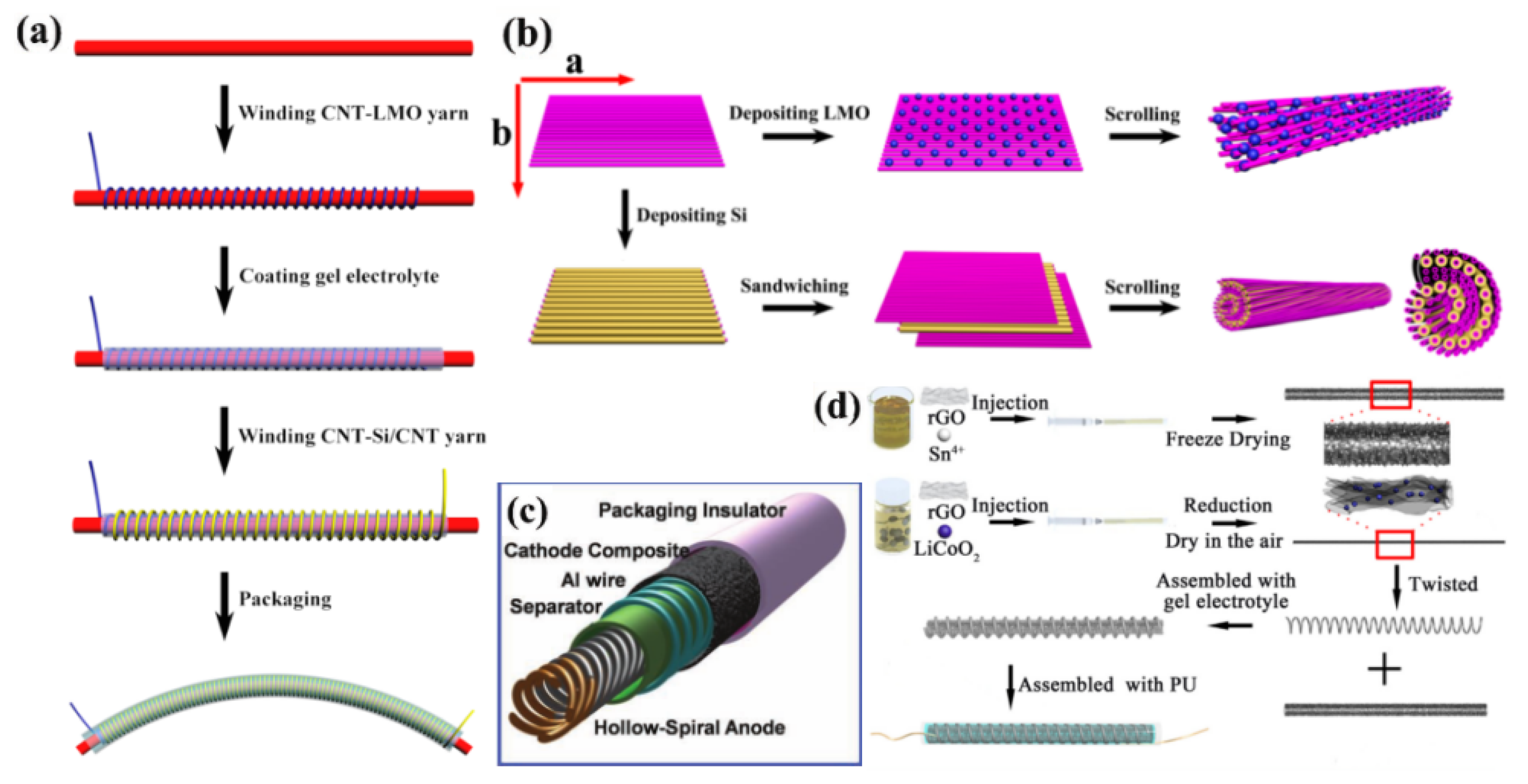
WEFLIBs consist of a central axis as well as wrapping fibers. The main axis can be any component of the cell (cathode, anode, electrolyte, or substrate), and the rest of the cell is wrapped around the central axis in the form of fiber yarns (Figure 11a). Weng et al. [116] first made a composite yarn of lithium manganate (LMO) combined with CNT as the cathode and a composite yarn of Si combined with CNT as the cathode (Figure 11b). The aligned CNT composite yarn cathode and anode were sequentially wound onto the cotton fiber to realize a fiber lithium-ion battery. In particular, it has a linear energy density of 0.75 mWh/cm and is successfully used in textiles. This structure can cope well with the volume expansion of Si during charging and discharging and has good flexibility. In addition, Yo Han Kwon et al. [102] made WEFLIBs by winding the anode and surrounding the anode with a tubular cathode (Figure 11c). Rao et al. [105] fabricated a WEFLIB by using annealed spring-like LiCoO 2 nanopartiles@graphene oxide (rGO) fibers as the cathode material, and SnO 2 quantum@rGO fibers as the anode material. As the anode material, flexible and self-healing WEFLIBs were fabricated (Figure 11d). After five repairs and 50 cycles of charging and discharging, half of the capacity is still retained.
WEFLIBs have good bending performance and can be easily adjusted for battery performance. However, due to the different shapes of positive and negative electrodes, there are some difficulties in matching the energy density of positive and negative electrodes.

3.1.2. HEFLIBs

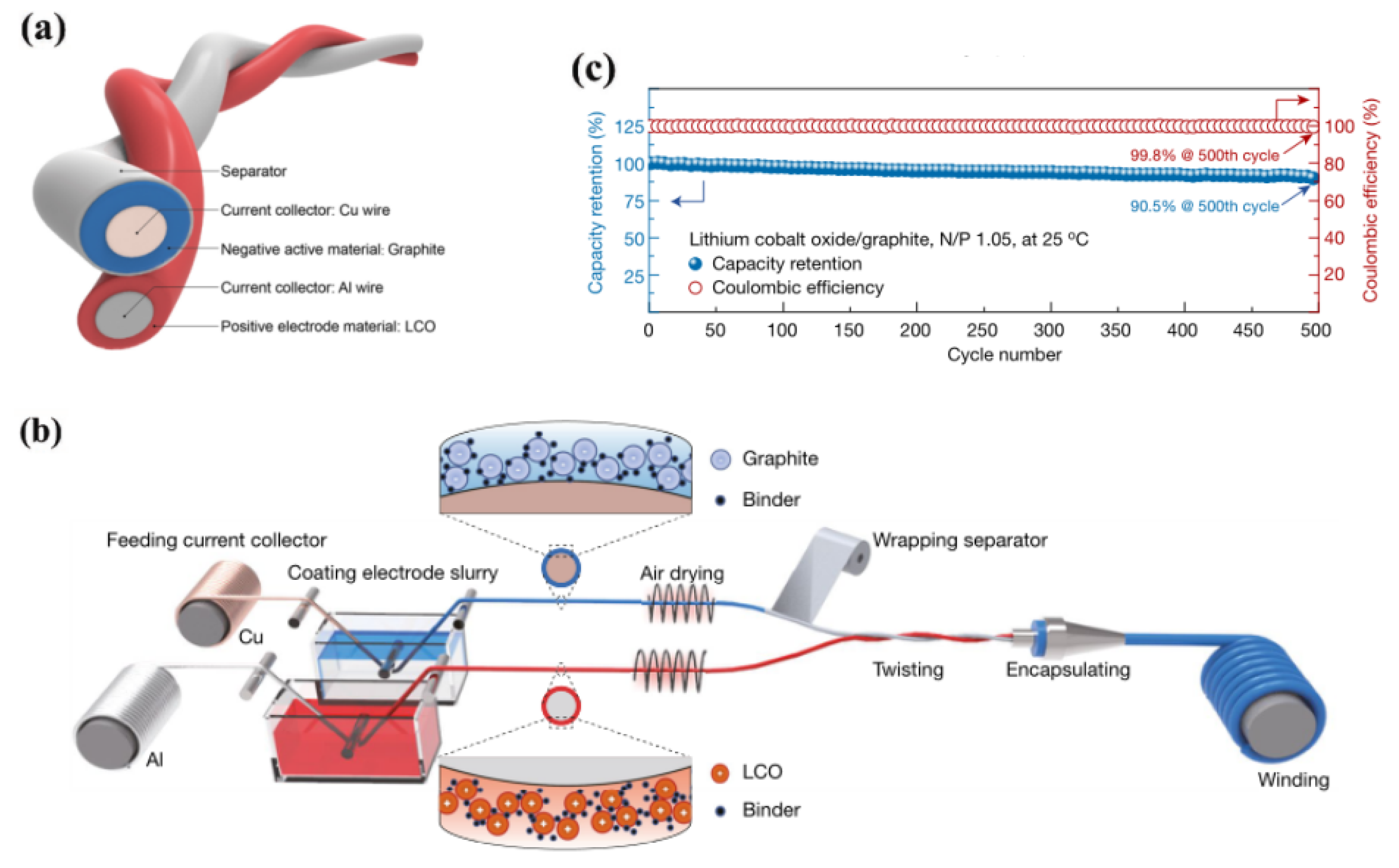
HEFLIBs are structures that require winding, but unlike WELIBs, the poles are wound together similar to the double helix structure of DNA (Figure 12a). He et al. [106] first coated lithium cobaltate (LCO) around a commercial aluminum wire to form the positive electrode and graphite around a copper wire to form the negative electrode, and then screwed the positive electrode and the negative fiber electrode wrapped around the septum. The positive electrode and the negative fiber electrode wrapped around the diaphragm are then screwed together to create the HEFLIB (Figure 12b). The mass-produced battery has an energy density of 85.69 Wh/kg (with a capacity retention of 90.5% after 500 charge/discharge cycles) and a multiplier capacity retention of 93% at 1 C (compared to 0.1 C multiplier capacity), which is comparable to commercial batteries such as soft pack batteries. After bending the fiber 100,000 times, it can retain more than 80% of its capacity (Figure 12c). As can be seen, the helical structure can better cope with the strain that occurs during deformation when stretching and bending. It has better cycling performance than the fiber cell with a central axis structure. The helical structure also allows the positive and negative electrodes to have more contact area with the electrolyte to increase the ion transfer efficiency. The similar shape of the positive and negative fibers also makes it easier to match the energy density of the positive and negative electrodes.

3.1.3. PEFLIBs

PEFLIBs are constructed by co-encapsulating mutually parallel positive and negative electrodes in an outer package (Figure 13a) [107,117]. Zhang et al. [118] used this structure to seal two fiber electrodes in a heat-shrinkable tube using a polyimide (PI)/carbon nanotube (CNT) hybrid fiber as the negative electrode and a LiMn 2 O 4 /carbon nanotube hybrid fiber as the positive electrode. A novel fibrous Li-ion battery was developed (Figure 13b). The cell has an output power density of 10,217.74 W/kg, which exceeds most supercapacitors, and an energy density of 48.93 Wh/kg. Based on the mass of PI and a discharge voltage plateau of 1.4 V, the full cell exhibits a specific discharge capacity of 123 mA h/g at a current rate of 10 C (1 C = 183 mA/g). Notably, the charging and discharging curves hold well at increasing current rates, even at 100C, with a specific capacity of 101 mAh/g (Figure 13c). Moreover, this fibrous cell has good bending properties and can be applied in textiles (Figure 13d).
However, the electrodes of all the above PEFLIBs need to be prepared separately, which is unfavorable for industrialization. Tural Khudiyev et al. [119] fabricated PEFLIBs using thermal stretching. This method simultaneously flows multiple complex electroactive gels, particles, and polymers within a flexible protective cladding. This top-down approach allows the production of fully functional and arbitrary-length lithium-ion fiber cells. A continuous 140 m fiber cell has a discharge capacity of 123 mAh and a discharge energy of 217 mWh. These fibers’ scalability and material tunability allow their use in various non-planar electronic systems, including 1D flexible electronic fibers, 2D woven electronic fabrics, and 3D printed structural electronic systems (Figure 13e).

3.1.4. CEFLIBs

Unlike the parallel design of the PEFLIB, the two electrodes in the CEFLIB are arranged in a coaxial configuration, where the solid fiber electrode, which serves as the core, is wrapped by the outer electrode. This structural design maximizes the contact area between the electrode and the collector and further reduces the internal resistance of the device. In addition, this design allows for close contact between multiple components and minimizes the amount of electrolyte required in the device. This will ensure a better definition of the electrochemical characteristics of the CEFLIB. Using the CEB configuration, Yadav et al. [120] designed and fabricated the first microfiber LIB (Figure 13f). Specifically, a lithium iron phosphate (LFP) positive layer was first deposited onto a carbon fiber (CF) collector by an electrophoretic deposition process. Then, an SPE layer of LiTFSI-PEO was coated on the prepared positive layer electrode. After that, the resulting CF/LFP/SPE fiber (as the core) is covered with the LTO anode layer using an electrophoretic deposition process similar to the cathodes. Then, a carbon layer consisting of CB, PEO, and MWCNT is applied as the anode collector to complete the cell assembly. The final thickness of the resulting fibrous LIB is about 22 μ m and has a cross-sectional structure typical of CEFLIBs. As a result, the cell shows high multiplier performance with a discharge area capacity of 3.1 μ Ah/cm 2 at 26 μ A/cm 2 and 4.2 μ Ah/cm 2 at 13 μ A/cm 2 . In addition, the battery maintained good constant current discharge performance in the bending test, indicating its potential application in flexible and wearable devices.
One-dimensional fiber-shaped batteries have many interesting properties and promising advantages over conventional bulk or flat-structured batteries: (1) Fiber-shaped batteries are highly compatible with the current textile industry. (2) Fabrics are woven/knitted from fiber-shaped batteries that can be breathable and have excellent ergonomic performance [118]. (3) Fiber-shaped batteries can be used in various flexible electronic devices with unparalleled flexibility, compatibility, and miniaturization potential, offering many possibilities [115,121,122].
However, this type of battery also faces many challenges: (1) High internal resistance. The resistance of fibrous cells increases with length, and very long fibrous cells are usually required in smart clothing. However, scholars have made progress in this area [106,119]. (2) Manufacturing difficulties. Care must be taken to avoid short circuits in the manufacturing process using slender electrodes. (3) Thickness is challenging to minimize. A cell is an electrochemical device with an electrolyte, a diaphragm, and two electrodes. Due to the complex structure, current fibrous cells are usually much thicker than ordinary yarn. (4) Yarn texture is difficult to achieve if used in smart clothing. With or without encapsulation, fibrous cells have the texture of plastic yarn rather than soft multi-strand yarn. (5) Insufficient tensile properties. The fibrous structure leads to insufficient tensile properties.

3.2. 2D Film-Shaped FLIBs

Macroscopically, 2D film-shaped FLIBs are cells with a thin film shape. Compared with 1D fiber-shaped FLIBs, they are more suitable for the existing cell production process. Depending on the shape of electrodes and cell structure, they can be classified into unit-film FLIBs (UFFLIBs), grid-pattern FLIBs (GPFLIBs), island-pattern FLIBs (IPFLIBs) and coplanar-electrode FLIBs (CPFLIBs). All these cells have good bending, stretching, and even transparency.

3.2.1. UFFLIBs

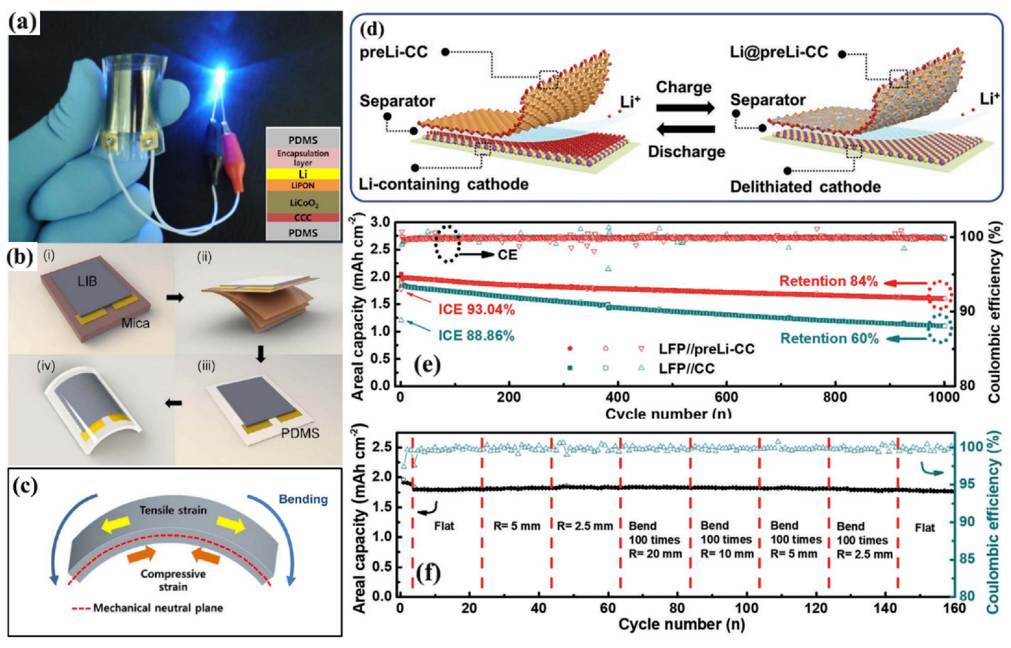
UFLIB is manufactured by stacking all the components of a battery together. This structure is similar to a sandwich and is the most widely used battery structure. This structure has received a lot of research [123,124,125]. Koo et al. [103] developed a UFLIB by using a generic transfer method (Figure 14a). The construction of the UFFLIB starts from a standard fabrication process with a brittle material mica substrate. A cathode current collector (CCC), a lithium cobalt oxide cathode (LiCoO 2 ), a lithium phosphorus oxynitride electrolyte (LiPON), a lithium (Li) metal anode, and a protective material package are deposited on the substrate sequentially (Figure 14b). When the cell is bent, the polydimethylsiloxane (PDMS) tensile strain appears on one side, and the compressive strain appears on the other side, and the balance between the opposite strains forms the force balance plane in which the full cell is placed (Figure 14c). The resulting full cell has an excellent bending ability and can reach a bending radius of 3.1 mm. However, the specific capacity of this UFLIB is too low for practical application. Xie et al. [108] reported a novel flexible hybrid lithium-ion/metal battery (f-LIMB). This battery uses prelithiated carbon cloth (preLi−CC) as the anode and LiFePO 4 as the cathode (Figure 14d). The pre-LIMB process introduces additional Li + into the anode and eases the subsequent Li metal deposition. Compared to the previous study, the f-LIMBs showed higher initial Coulomb efficiency, higher energy density, and higher capacity retention (84% after 1000 cycles) (Figure 14e). The good electrochemical performance of the cells was well maintained even after bending them hundreds of times with a small radius of 2.5 mm (Figure 14f).

3.2.2. GPFLIBs

GPFLIB is constructed by confining electrode materials and metal collectors within grid trenches with specific patterns on a transparent substrate to fabricate electrodes and then sandwiching the electrolyte between two such grid-patterned electrodes. This makes the thin-film cell less internally stressed when bending, and the electrodes are less likely to be damaged by bending, and GPFLIB makes transparent cells possible. Yang et al. [126] fabricated a transparent lithium battery by a microfluidic-assisted method (Figure 15a). The feature size of the electrodes in the cell is below the resolution limit of the human eye, so the electrodes appear transparent. Furthermore, by aligning multiple electrodes, the stored energy can be easily increased without sacrificing transparency. Ultimately, an energy density of 10 Wh/L and 60% transparency can be achieved. The transparent full cell is made by sealing the LiMn 2 O 4 electrode/gel electrolyte/Li 4 Ti 5 O 12 electrode in a transparent plastic bag. The average discharge voltage was 2.4 V. The initial discharge capacity was 100 mAh/g, which remained above 80 mAh/g after 15 cycles (Figure 15b). The transparent full cell can be used to repeatedly light up red light-emitting diodes (LEDs) (Figure 15c), and the cell also has good flexibility. However, the electrode structure of GPFLIB is challenging to meet the dual requirements of flexibility and specific capacity. The gridded electrodes have a smaller area than other thin-film electrodes, and the percentage of active material in the cell becomes very low. Although it is possible to increase the amount of active material in the cell by increasing the number of electrode layers, the flexibility is reduced.

3.2.3. IPFLIBs

IPFIB is to design electrodes into small cells (similar to islands) on a flexible substrate and then connect one small cell to another with an adjustable metal or flexible structure (Figure 16a). Xu et al. [109] used a “self-similar” serpentine structure. In this cell, LiCoO 2 and Li 4 Ti 5 O 12 were used as the active materials for the cathode and anode, respectively, to make small cells (islands) of the same shape. The collectors of copper and aluminum were driven into the same islands as the electrodes. The collectors were connected by two serpentine wires (Figure 16b,c), thus interconnecting the island electrodes. The prepared IPFLIB has good stretching properties and can be biaxially stretched up to 300% (Figure 16d) and can light up the LED under stretching and bending (Figure 16e). Yin et al. [110] used the same structural design to mount a button Li-ion battery pack onto the island region of a screen-printed, flexible, polymer-reinforced interconnected “island bridge” array (Figure 16f). This structural design allows the battery pack to be used directly to light the LED at the elbow (Figure 16g). Luo et al. [127] proposed the design of interlocking compact textile electrodes (ICTEs) (Figure 16h), inspired by the rigid and flexible segment structure of a bamboo mat. A simple and scalable pre-rolling treatment formed uniformly aligned cracks on both sides of the high-stacking density ICTEs. This increased surface capacity (4.5 mAh/cm 2 ) and bending stability (20,000 bending cycles).
Figure 16. (a) Schematic illustration of a completed IPFIB, in a state of stretching and bending. (b) The image of interconnecting self-similarity electrodes on a Si chip with an Al collector. (c) Illustration of ‘self-similar’ serpentine geometries used for the interconnects (black: 1st level serpentine; yellow: 2nd level serpentine). (d) Biaxially stretched to 300%. (e) Mounted on the human elbow [109]. (f) Assembly of the printed array and Li-ion coin cell batteries using anisotropic conductive paste as adhesive. (g) Assembled LED band on body [110] (h) Schematic of bamboo mat-inspired IPFLIB design [127]. (ae) Reproduced with permission [109]. Copyright 2013, Springer Nature. (f,g) Reproduced with permission [110]. Copyright 2018, John Wiley & Sons-Books. (h) Reproduced with permission [127]. Copyright 2023, Elsevier Science & Technology Journals.
Energies 16 04549 g016
In this design, the island cells are fabricated to be stiff enough to prevent them from breaking and are electrically connected by stretchable metal interconnections on a stretchable substrate, allowing the entire system to accommodate mechanical deformation without applying excessive pressure to individual cells on them. Thus, the system so constructed is characterized by excellent stretchability. The island-structured electrodes of the IPFLIB will also have more active material than the GPFLIB, increasing the specific capacity of the cell.

3.2.4. CPFLIBs

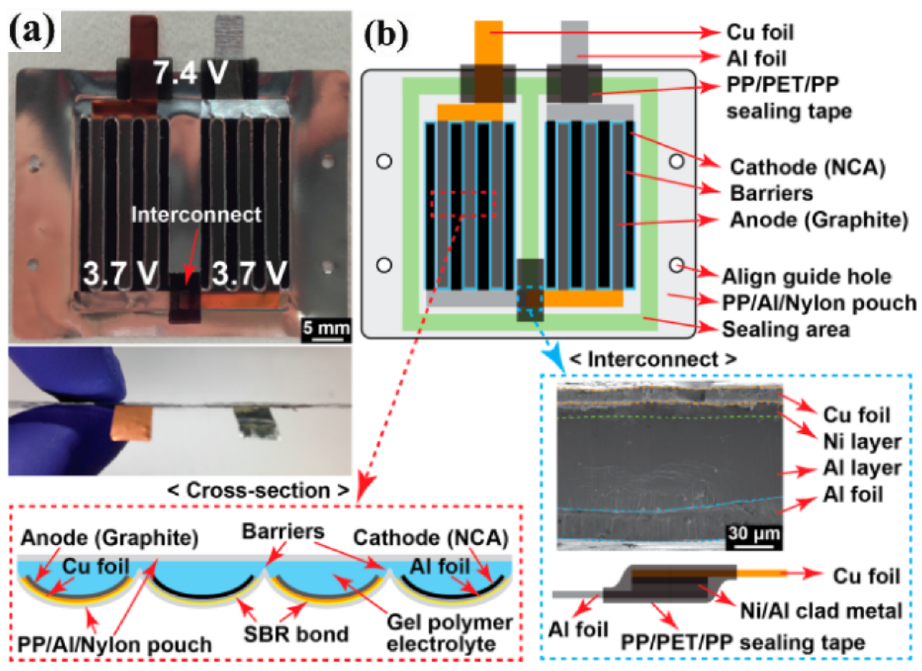
The above three 2D film-shaped FLIBs all follow the laminated structure of conventional cells. In contrast, the positive and negative electrodes of the CPLIB are arranged crosswise in the same plane. This structure can further reduce the thickness of the film-like cell to improve the bending performance of the cell. Kim et al. [111] designed a CPFLIB in which the anode and cathode were cross positioned in the same plane (Figure 17a). In this CPFLIB, fork-finger electrodes were prepared by using graphite and LiNi 0.8 Co 0.15 Al 0.05 O 2 (NCA) as the anode and cathode active materials, respectively, and the curved geometry of each electrode had a pocket barrier between the adjacent anode and cathode (Figure 17b). The specific capacity of this cell is 130 mAh/g, and the overall cell thickness is less than 0.5 mm. More importantly, the barrier between the electrodes effectively releases the stress under bending and prevents the electrode material from breaking, thus ensuring good bendability of the cell. Even after 5000 cycles of bending at end-to-end distances of 45 to 10 mm, the assembled CPFLIB shows stable discharge performance for powering six LEDs.
As mentioned above, several types of 2D thin-film cells have been developed by changing the electrode shape and the cell configuration. One of the most accessible thin-film cells to produce is the UFFLIB, which is the most similar structure to conventional cells. Although the bending performance of this cell has been achieved to a reasonable extent, its electrode structure makes it less ductile. Based on the UFFLIB, researchers invented the GPFLIB, a system with a lattice of electrodes that allows the electrodes to be less stressed during bending, not easily damaged, and allows the battery to achieve more functionality (transparency) [126]. However, the latticed electrodes reduce the percentage of active material, which is not conducive to increasing the specific capacity of the cell and poses practical difficulties. IPFLIB can be considered an upgraded version of GPFLIM, which increases the electrodes’ active material while enhancing the cell’s flexibility and stretchability [109,110,127]. However, this structure still sacrifices some of the energy and power density for UFFLIB. CPFLIB possesses good bending performance and is the smallest thick cell among these four thin film-like cells, which is suitable for card application.

3.3. 3D FLIBs

Three-dimensional FLIBs have many different configurations. Based on the study of thin film-like cells, Liu et al. [128] prepared FLIBs using a wavy structure. Folding the entire soft pack cell into a wavy shape and filling each valley region with polydimethylsiloxane, all components, including the package, can reversible stretching (Figure 18a). The wave-shaped cell has good electrochemical performance and long-term stability in repeatable release-stretch cycles. The wave-shaped cell achieves a high area capacity of 3.6 mAh/cm 2 and an energy density of up to 172 Wh/L. Also, Ahmad et al. [112] achieved cell flexibility based on thin film-like cells by decoupling the electrodes. This study was done by designing CNT microstructures (Figure 18b) to achieve extremely flexible cells, which separate the stresses induced during collector bending from the stresses during bending of the energy storage materials (Fe 2 O 3 anode and lithium nickel cobalt oxide(LNCO) cathode). This cell architecture provides not only excellent flexibility (bending radius ≈ 300 μ m), but also high multiplicity (20 A/g) and cycling stability (more than 500 cycles at 1 C with capacity retention over 70%).
Figure 18. (a) Schematic diagram of a stretchable Wavy battery and its material composition [128]. (b) Schematic diagram of a flexible battery with decoupled electrodes [112]. (c) Two examples of using Miura folded origami LIBs. The image at the bottom left refers to a 45 fold, which can be compressed in one direction. The image in the lower right corner refers to a 90 fold, which can be fully folded in the biaxial direction [129]. (d) The schematic illustration of designing flexible snake-origami batteries. (e) The cycle performance of snake-origami batteries with different states [130]. (a) Reproduced with permission [128]. Copyright 2017, John Wiley & Sons-Books. (b) Reproduced with permission [112]. Open access, Creative Commons Attribution License (CC BY). (c) Reproduced with permission [129]. Copyright 2014, Springer Nature. (d,e) Reproduced with permission [130]. Open access, Creative Commons Attribution License (CC BY).
Energies 16 04549 g018
In addition to the above strategies, origami and kirigami are common strategies for designing 3D FLIBs [104,131]. Origami and kirigami methods are inspired by origami and paper cutting, respectively. The origami method allows rigid electrodes to be bent in a pre-designed manner by pre-folding. Song et al. [129] made an origami cell using Miura pattern folding (Figure 18c). However, a high level of deformability can be achieved where the crease specifies the system-level deformability and the substrate used to make the origami pattern does not experience large strains except at the crease. However, the bending of this battery is limited by the crease and cannot be achieved in any direction. Li et al. [130] designed and fabricated a new bi-directional flexible snake-shaped origami lithium-ion battery with both high energy density and good flexibility (Figure 18d). The rigid part of the cell is the energy cell, and the flexible element is the deformation cell. The bending capability of the cell is increased while reducing the loss of energy cells. The snake origami FLIB produced has an excellent energy density of 357 Wh/L (133 Wh/kg), and even under different mechanical deformations and 5000 cycles of continuous bending, it has strong energy storage performance (Figure 18e). This rigid–flexible coupling approach provides a new way of thinking about the origami battery. A similar structure to the origami structure is the kirigami structure.
The kirigami structure can reduce the stress changes generated inside the cell during deformation by cutting the material into a specially designed pattern using a geometric topology. The structure maintains stable electrochemical properties when large deformations occur. Song et al. [132] produced stretchable lithium-ion batteries using the concept of paper cutting, i.e., a combination of folding and cutting. In this work, the researchers used three structures: a zigzag-cut pattern, a cut-N-twist pattern, and a cut-N-shear pattern. The zigzag-cut pattern (Figure 19a) represents one of the most common paper-cut patterns, which is created by the zigzag-cut pattern. Figure 19a represents one of the most common paper-cutting patterns, which is made by cutting asymmetrically between adjacent folds to create serrated-like cuts in the longitudinal direction. The jagged pattern can be stretched beyond its length in the planar state. However, the stretching process stresses the plane. To change the cell force, the cut-N-twist pattern was used again (Figure 19b), in which the folded foil is cut symmetrically at all creases, then unfolded into the planar state, and then twisted at the ends. The deformation in the non-folded region is limited during stretching, but rotation occurs at the cut to accommodate the stretch. The cut-N-shear pattern was used to improve the energy density further and increase the non-folded regions’ overlap (Figure 19c). This model, where folding is used after symmetric cuts, doubles the stacking density. The battery fabricated using the cut-N-shear pattern can power a smartwatch during stretching (Figure 19d). Bao et al. [133] invented another fishing net structure based on the study of the zigzag-cut pattern (Figure 19e). The cell elongation of this fishing net structure is only three-tenths of the zigzag structure. After 500 stretch-release cycles, the LFP half-cell provides 145 mAh/g of capacity after 50 discharge/charge cycles for the fishnet structure and 130 mAh/g for the zigzag structure. It can be seen that this fishing net structure has a slight increase in capacity but loses the deformation capacity of the battery.
Figure 19. (a) A zigzag-cut pattern, where the out-of-plane deformation occurs to accommodate stretching. (b) A cut-N-twist pattern, where the rotation is involved to accommodate stretching and no out-of-plane deformation. (c) A cut-N-shear pattern, where the packing density doubles compared with that of the cut-N-twist pattern. Rotation is involved to accommodate stretching and no out-of-plane deformation. (d) Powering a smart watch by a kirigami LIB using cut-N-twist pattern [132]. (e) Illustration of customized kirigami deformable electrodes under stretched states [133]. (ad) Reproduced with permission [132]. Open access, Creative Commons Attribution License (CC BY). (e) Reprinted (adapted) with permission from Ref. [133]. Copyright 2020 American Chemical Society.
Energies 16 04549 g019
Besides origami and paper-cutting, many structures in life can inspire designing flexible lithium-ion batteries. Inspired by accordions, Shi et al. [113] designed accordion-like batteries that can reduce collector stress (Figure 20a). Moreover, this battery can achieve 29% stretchability while maintaining 77% of the conventional filler bulk energy density (233 Wh/L). Even after 22% stretching for 10,000 cycles, bending for 20,000 cycles, and 0.5 C cycling for 100 cycles, the battery still shows a high-capacity retention of 95.4%. It can be seen that this structure has high-capacity retention after stretching and bending.
All of the above are artificial structures in life that bring inspiration to flexible lithium-ion batteries. Among nature, plants and animals have developed unique structures through natural evolution for quite a long time, and these structures have high mechanical deformation capacity and stability. Bionic FLIBs are also a direction for structure design. Qian et al. [134] fabricated a spine-like flexible lithium-ion battery. A thick, stiff part that stores energy by winding the electrodes corresponds to an animal vertebra. In contrast, a thin, unwound, flexible part acts as the marrow to hold all the vertebra-like stacks together, providing excellent flexibility to the entire cell (Figure 20b). The maximum strain for this cell design (≈0.08%) is significantly less than that of a conventional stacked cell (≈1.1%). In the human body, the joints, in addition to the spine, also offer excellent flexibility. Chen et al. [135] designed the FLIB to mimic the articular surface-ligament structure of human joints (Figure 20c). At the joints in the cell, it consists of two thick rigid stacks and a soft part. The thick rigid stack has a curved surface corresponding to the joint head of a bone, facilitating the cushioning of stresses and providing the cell’s main energy. The soft part acts as a ligament, interconnecting the thick rigid stack and providing flexibility. It has a better elongation than the spinal structure. The battery performs stable cycling after 100,000 dynamic stretches, 20,000 extreme twists, and 100,000 complex bending+twisting deformations (Figure 20d). It is possible to charge smartphones under various deformation conditions (Figure 20e). The spiral structure is a common FLIB design direction [136]. Meng et al. [137] designed a FLIB with high helical deformability and long-life cycling stability inspired by the double helix structure of DNA (Figure 20f). The cell structure consists of several thick energy stacks for energy storage and some grooves for stress buffering. According to the results, the capacity drop of the cell is less than 3% even after more than 31,000 in situ dynamic mechanical loads.
In addition to bionic structures on the human body, bionic mechanisms inspired by a reptile epidermis have been used for FLIB design in recent years. Kim et al. [138] investigated a FLIB with a snake-scale-like structure (Figure 20g). This structure overlaps similar independent cells and connects the independent cells with a snakeskin-like hinge structure to achieve stable deformation. The deformable nature of this cell structure allows it to be applied in the field of soft robotics (Figure 20h,i). Liu et al. [114] designed a rigid-flexible FLIB inspired by crocodile skin (Figure 20j). The cell has excellent bulk energy density and maintains stable electrochemical performance even after 30,000 bending cycles and 200 charge/discharge cycles, with 92.3% capacity retention per cycle and 0.038% capacity decay (Figure 20k).
The above discussion shows the wide variety of structures that can be used in 3D FLIBs. Structures can be inspired by basic electrode designs, origami and paper cutouts, and even bionic inspiration. Three-dimensional FLIBs can be considered an upgrade of 1D fiber-shaped FLIBs and 2D film-shaped FLIBs. However, the process of 3D cells is relatively complex, and how to have a more straightforward manufacturing method to industrialize them is a challenge.
By comparing the various structures of flexible solid-state lithium-ion batteries introduced above, it can be found that different structures can be selected based on different mechanical properties. The main factor affecting structural selection is the elongation rate. In 1D fiber-shaped FLIBs, the elongation rate is very low, but the tensile strength is high, and the battery can withstand a large tensile force. So, when batteries need to handle tension, 1D fiber-shaped FLIBs are often chosen. The stretching rate has been significantly improved in 2D film-shaped FLIBs. Two-dimensional film-shaped FLIBs are often chosen when the strength requirement is low and various deformations can be achieved. The structure with the best tensile strength is 3D FLIBs, and the diversity of 3D FLIBs can meet various bending needs. When there is a high demand for the mechanical properties of electrodes (both good bending and tensile properties and high strength are required), it is often necessary to choose 3D FLIBs or even customize the structure according to the mechanical performance requirements.
In the various structures of batteries mentioned above, in addition to mechanical properties, electrochemical performance also has important reference value. Among the three structures introduced earlier, 1D fiber-shaped FLIBs have the worst mechanical performance and the worst specific capacity among the three, but their capacity retention rate is the highest. The specific capacity and cycling performance of 2D film-shaped FLIBs with moderate mechanical performance are also at an intermediate level. The mechanical performance and specific capacity of 3D FLIBs are the best, but their capacity retention and magnification performance are the worst among these three structures.
Figure 20. (a) The design of the accordion-like battery [113]. (b) Schematic diagram of the structure and manufacturing process of a spine-like battery [134]. (c) Schematic diagram of battery structure inspired by joints. (d) Cycling performance of the battery under dynamic bending+twisting. (e) Powering the smartphone with a battery under different deformations [135]. (f) DNA helix structure and the helix-inspired battery design [137]. (g) Schematic diagram of flexible battery structure inspired by snake scales. (h) Application of untethered tubular actuator producing crawling movement. (i) A soft robot covered in deformable scale batteries [138]. (j) Structural schematic diagram of FLIB inspired by the arrangement array of bone skins in crocodile skin. (k) The cycling performance in different deformation conditions for 200 cycles at 0.5 C and 1 C [114]. (a) Reproduced with permission [113]. Copyright 2019, Elsevier Science & Technology Journals. (b) Reproduced with permission [134]. Copyright 2019, John Wiley & Sons-Books. (ce) Reproduced with permission [135]. Copyright 2021,Royal Society of Chemistry. (f) Reprinted (adapted) with permission from Ref. [137]. Copyright 2022 American Chemical Society. (gi) Reproduced with permission [138]. Copyright 2022, Mary Ann Liebert Inc. (j,k) Reproduced with permission [114]. Copyright 2022, Elsevier Science & Technology Journals.
Energies 16 04549 g020

4. Conclusions and Outlook

Over the past period, tremendous progress has been made in researching flexible lithium-ion batteries. To make flexible batteries with both high electrochemical performance (including increased energy, high power, high safety, and long cycle life) and excellent mechanical deformability (such as bendability, foldability, stretchability, compressibility, and twistability), both flexible and easily deformable structures of the battery constituent parts should be fully considered. To address this goal, in this review, we review the flexible materials applied in FLIBs and the structural design of FLIBs.
First, in FLIBs, collectors are often combined with electrode materials to reduce the presence of interfaces to achieve higher energy density, rate performance, and flexibility. CNT and graphene have high electrical conductivity, specific surface area, and excellent mechanical strength and are outstanding contributors to increasing electrode energy density and multiplier performance. However, the high price of these nanomaterials makes them difficult to be used in industrial applications. Moreover, combining active materials with CNT or graphene often requires the presence of a binder, which also results in a loss of energy density. Therefore, CF and CC have emerged in the research of flexible electrodes. The same carbon material, CF and CC, have lower prices. The internal structure of CF and CC can eliminate the use of binders and further increase the proportion of active material. It can be seen that carbon materials have a significant role in flexible electrodes. The research on CF and CC has laid the foundation for the industrialization of flexible electrodes. However, how to make more active materials born on or deposited on carbon materials is a challenge that still needs to be faced in the future.
Secondly, conductive polymers are considered the most promising materials for flexible Li-ion electrodes. Conductive polymers have many advantages, such as structural diversity, tunable molecular structure and method, tunable redox potential, and high specific capacity. Still, they face significant challenges in capacity decay, low electronic conductivity, electrode dissolution, and side reactions.
Thirdly, electrolytes have been eliminated in developing flexible batteries because of their hazardous nature. ISEs, SPEs, and GPEs are the most used electrolytes in LIBs, which are solid and can cope with the various deformation needs of batteries. Moreover, solid electrolytes can inhibit the growth of dendrites and have the advantages of thermal stability, mechanical strength, flexibility, and denseness. However, improving the ion mobility and the interface with electrodes in solid electrolytes is still a significant challenge.
Fourthly, the structural design significantly impacts the mechanical and electrochemical properties of FLIBs. Based on the differences in electrode structures, flexible cells can be designed in multiple dimensions ranging from 1D fibrous, 2D thin-film to 3D structures to cope with various deformations. Specifically, with different advantages and disadvantages, 1D cells have been implemented in multiple configurations in WEFLIB, HEFLIB, PEFLIB, and CEFLIB. With their unique fiber-like structure, 1D cells are expected to be a flexible power source for wearable electronics, either woven with existing fabrics/textiles or directly into textiles. However, there are many challenges to be faced in the industrialization process, one of which is that the internal resistance increases to a high level as the length of the fibrous cell increases. The incorporation of highly conductive carbon materials in the electrodes is one solution. The poor tensile properties of fibrous cells are also challenges to be faced. Two-dimensional cells include UFFLIB, HEFLIB, PEFLIB, and CPFLIB. UFFLIB has the advantage of being easy to manufacture, but its stacked manufacturing method makes it poor in bending cycles. The grid-like electrodes of GPFLIM can solve the problem of poor bending performance to a certain extent. However, its less active material content will reduce the specific capacity of the cell. IPFLIB synthesizes the first two 2D cells and performs better in both mechanical and electrochemical properties. The biggest challenge of CPFLIB is how to shorten the physical distance between negative and positive electrodes to enhance the high multiplicity performance of the cell. Based on the 1D and 2D batteries, the application of 3D batteries is a further improvement of the mechanical and electrochemical performance of the battery, making it more suitable for application in flexible devices. However, the structures of 3D batteries are complex, and the industrialization process still faces challenges.
Fifth, the selection of materials and structures has a direct impact on the specific energy of batteries. Different carbon materials have different microstructures, which have different capacities for accommodating active substances. Electrode materials that can accommodate more active substances have higher specific energy. In this regard, CNT and graphene have higher specific surface areas, providing more attachment sites for nano active substances at the micro level. Therefore, electrodes containing CNT or graphene often have higher specific energy. Carbon cloth, due to its complex internal structure, can also provide more attachment sites for active substances, and the electrodes composed of it have a higher specific energy. CNT and graphene materials have better binding ability with nano active substances. However, in the process of industrialization, the high price of CNT and graphene cannot bridge the gap. In the process of industrialization, carbon cloth and carbon fiber will be better choices for electrode materials. Among the three different structures of batteries, the different macroscopic structures do not have a significant impact on the energy of the battery. Different structures have a significant impact on industrialization, among which 1D batteries have been industrialized and production lines have been proven to be capable of production. The industrialization of 2D batteries also draws inspiration from traditional coating methods. However, the industrialization of 3D batteries faces difficulties in mass production. For the industrialization of 3D batteries, 3D printing molding is a good direction.
Sixth, the safety issues of flexible lithium-ion batteries have also received widespread attention in research work. Traditional batteries are prone to problems such as leakage, combustion, and explosion due to the poor thermal stability of the electrolyte. In flexible lithium-ion batteries, the traditional electrolyte and separator systems are replaced with solid-state electrolytes, which have good thermal stability and will not burn even at 230 C. This ensures the safety of flexible solid-state lithium-ion batteries.
Finally, through extraordinary advances made in the past and extensive research on key aspects of cell materials and structures, high-performance flexible solid-state cells with well-defined electrochemical properties and excellent mechanical deformability are expected to be widely used in various flexible electronic devices shortly.

Author Contributions

R.D.: methodology, investigation, writing, editing; T.H.: conceptualization, review, supervision, funding acquisition. All authors have read and agreed to the published version of the manuscript.

Funding

Project supported by the National Defense Science and Technology Innovation Zone Foundation of China.

Data Availability Statement

Not applicable.

Conflicts of Interest

The authors declare no conflict of interest.

References

  1. Yamada, T.; Tsubata, Y. Recent progress and future perspectives of light emitting polymers for full-color display. J. Synth. Org. Chem. Jpn. 2012, 70, 473–479. [Google Scholar] [CrossRef]
  2. Pang, C.; Lee, C.; Suh, K.Y. Recent advances in flexible sensors for wearable and implantable devices. J. Appl. Polym. Sci. 2013, 130, 1429–1441. [Google Scholar] [CrossRef]
  3. Sumboja, A.; Foo, C.Y.; Wang, X.; Lee, P.S. Large areal mass, flexible and free-standing reduced graphene oxide/manganese dioxide paper for asymmetric supercapacitor device. Adv. Mater. 2013, 25, 2809–2815. [Google Scholar] [CrossRef] [PubMed]
  4. Shim, B.S.; Chen, W.; Doty, C.; Xu, C.; Kotov, N.A. Smart electronic yarns and wearable fabrics for human biomonitoring made by carbon nanotube coating with polyelectrolytes. Nano Lett. 2008, 8, 4151–4157. [Google Scholar] [CrossRef] [PubMed]
  5. Zhong, J.; Zhang, Y.; Zhong, Q.; Hu, Q.; Hu, B.; Wang, Z.L.; Zhou, J. Fiber-based generator for wearable electronics and mobile medication. ACS Nano 2014, 8, 6273–6280. [Google Scholar] [CrossRef] [PubMed]
  6. Jeong, G.S.; Baek, D.H.; Jung, H.C.; Song, J.H.; Moon, J.H.; Hong, S.W.; Kim, I.Y.; Lee, S.H. Solderable and electroplatable flexible electronic circuit on a porous stretchable elastomer. Nat. Commun. 2012, 3, 977. [Google Scholar] [CrossRef] [Green Version]
  7. Lee, Y.H.; Kim, J.S.; Noh, J.; Lee, I.; Kim, H.J.; Choi, S.; Seo, J.; Jeon, S.; Kim, T.S.; Lee, J.Y.; et al. Wearable textile battery rechargeable by solar energy. Nano Lett. 2013, 13, 5753–5761. [Google Scholar] [CrossRef]
  8. Sun, D.m.; Timmermans, M.Y.; Tian, Y.; Nasibulin, A.G.; Kauppinen, E.I.; Kishimoto, S.; Mizutani, T.; Ohno, Y. Flexible high-performance carbon nanotube integrated circuits. Nat. Nanotechnol. 2011, 6, 156–161. [Google Scholar] [CrossRef]
  9. Qian, G.; Liao, X.; Zhu, Y.; Pan, F.; Chen, X.; Yang, Y. Designing flexible lithium-ion batteries by structural engineering. ACS Energy Lett. 2019, 4, 690–701. [Google Scholar] [CrossRef]
  10. Chen, R.; Li, Q.; Yu, X.; Chen, L.; Li, H. Approaching practically accessible solid-state batteries: Stability issues related to solid electrolytes and interfaces. Chem. Rev. 2019, 120, 6820–6877. [Google Scholar] [CrossRef]
  11. Lin, D.; Liu, Y.; Cui, Y. Reviving the lithium metal anode for high-energy batteries. Nat. Nanotechnol. 2017, 12, 194–206. [Google Scholar] [CrossRef]
  12. Zeng, L.; Qiu, L.; Cheng, H.M. Towards the practical use of flexible lithium ion batteries. Energy Storage Mater. 2019, 23, 434–438. [Google Scholar] [CrossRef]
  13. Chang, J.; Huang, Q.; Zheng, Z. A figure of merit for flexible batteries. Joule 2020, 4, 1346–1349. [Google Scholar] [CrossRef]
  14. Gu, Z.; Li, W.; Miao, Y.; Chen, Y.; Xia, X.; Chen, G.; Liu, H. Influencing factors and behavior mechanism of the initial coulombic efficiency of silicon/graphite composites in lithium-ion batteries. Electrochim. Acta 2021, 366, 137424. [Google Scholar] [CrossRef]
  15. Yu, M.F.; Lourie, O.; Dyer, M.J.; Moloni, K.; Kelly, T.F.; Ruoff, R.S. Strength and breaking mechanism of multiwalled carbon nanotubes under tensile load. Science 2000, 287, 637–640. [Google Scholar] [CrossRef] [PubMed] [Green Version]
  16. Hong, S.; Myung, S. A flexible approach to mobility. Nat. Nanotechnol. 2007, 2, 207–208. [Google Scholar] [CrossRef]
  17. Zhou, G.; Li, F.; Cheng, H.M. Progress in flexible lithium batteries and future prospects. Energy Environ. Sci. 2014, 7, 1307–1338. [Google Scholar] [CrossRef]
  18. Jin, T.; Han, Q.; Wang, Y.; Jiao, L. 1D nanomaterials: Design, synthesis, and applications in sodium–ion batteries. Small 2018, 14, 1703086. [Google Scholar] [CrossRef]
  19. Wei, Y.; Hu, Q.; Cao, Y.; Fang, D.; Xu, W.; Jiang, M.; Huang, J.; Liu, H.; Fan, X. Polypyrrole nanotube arrays on carbonized cotton textile for aqueous sodium battery. Org. Electron. 2017, 46, 211–217. [Google Scholar] [CrossRef]
  20. Jayasinghe, C.; Salunke, P.; Lee, L.; Head, E.; Mallik, N.; Yun, Y.; Pendyala, C.; Schulz, M.J.; Shanov, V.N. Extremely Long Multiwall Carbon Nanotube Arrays for Spinning Yarn. In Proceedings of the APS March Meeting Abstracts, Louisiana, OR, USA, 10–14 March 2008; p. C1.160. [Google Scholar]
  21. Tian, R.; Alcala, N.; O’Neill, S.J.; Horvath, D.V.; Coelho, J.; Griffin, A.J.; Zhang, Y.; Nicolosi, V.; O’Dwyer, C.; Coleman, J.N. Quantifying the effect of electronic conductivity on the rate performance of nanocomposite battery electrodes. ACS Appl. Energy Mater. 2020, 3, 2966–2974. [Google Scholar] [CrossRef]
  22. Yan, J.; Huang, H.; Zhang, J.; Liu, Z.; Yang, Y. A study of novel anode material CoS2 for lithium ion battery. J. Power Sources 2005, 146, 264–269. [Google Scholar] [CrossRef]
  23. Feng, C.; Ma, J.; Li, H.; Zeng, R.; Guo, Z.; Liu, H. Synthesis of molybdenum disulfide (MoS2) for lithium ion battery applications. Mater. Res. Bull. 2009, 44, 1811–1815. [Google Scholar] [CrossRef]
  24. Tang, S.; Yang, L.; Liu, J.; Fichou, D. Carbon coated hierarchical porous MoO2 nanoflowers as high-performance anodes in lithium-ion batteries. Mater. Res. Bull. 2018, 102, 277–281. [Google Scholar] [CrossRef]
  25. Dominko, R.; Arčon, D.; Mrzel, A.; Zorko, A.; Cevc, P.; Venturini, P.; Gaberscek, M.; Remskar, M.; Mihailovic, D. Dichalcogenide nanotube electrodes for Li-ion batteries. Adv. Mater. 2002, 14, 1531–1534. [Google Scholar] [CrossRef]
  26. Ding, S.; Chen, J.S.; Lou, X.W. Glucose-assisted growth of MoS2 nanosheets on CNT backbone for improved lithium storage properties. Chem. Eur. J. 2011, 17, 13142–13145. [Google Scholar] [CrossRef] [PubMed]
  27. Ban, C.; Wu, Z.; Gillaspie, D.T.; Chen, L.; Yan, Y.; Blackburn, J.L.; Dillon, A.C. Nanostructured Fe3O4/swnt electrode: Binder-free and high-rate li-ion anode. Adv. Mater. 2010, 22, E145–E149. [Google Scholar] [CrossRef]
  28. Baughman, R.H.; Zakhidov, A.A.; De Heer, W.A. Carbon nanotubes–the route toward applications. Science 2002, 297, 787–792. [Google Scholar] [CrossRef] [Green Version]
  29. Huang, Y.H.; Goodenough, J.B. High-rate LiFePO4 lithium rechargeable battery promoted by electrochemically active polymers. Chem. Mater. 2008, 20, 7237–7241. [Google Scholar] [CrossRef]
  30. Zhang, Y.; Li, F.; Yang, K.; Liu, X.; Chen, Y.; Lao, Z.; Mai, K.; Zhang, Z. Polymer Molecular Engineering Enables Rapid Electron/Ion Transport in Ultra-Thick Electrode for High-Energy-Density Flexible Lithium-Ion Battery. Adv. Funct. Mater. 2021, 31, 2100434. [Google Scholar] [CrossRef]
  31. Amin, K.; Meng, Q.; Ahmad, A.; Cheng, M.; Zhang, M.; Mao, L.; Lu, K.; Wei, Z. A carbonyl compound-based flexible cathode with superior rate performance and cyclic stability for flexible lithium-ion batteries. Adv. Mater. 2018, 30, 1703868. [Google Scholar] [CrossRef]
  32. Yu, Y.; Luo, Y.; Wu, H.; Jiang, K.; Li, Q.; Fan, S.; Li, J.; Wang, J. Ultrastretchable carbon nanotube composite electrodes for flexible lithium-ion batteries. Nanoscale 2018, 10, 19972–19978. [Google Scholar] [CrossRef] [PubMed]
  33. Lee, J.S.; Yun, S.D.; Nyamaa, O.; Yang, J.H.; Huh, S.C.; Jeong, H.M.; Nam, T.H.; Ryu, Y.J.; Noh, J.P. Free-Standing Li4Ti5O12/Carbon Nanotube Electrodes for Flexible Lithium-Ion Batteries. Energies 2022, 15, 8585. [Google Scholar] [CrossRef]
  34. Zhang, P.; Qiu, J.; Zheng, Z.; Liu, G.; Ling, M.; Martens, W.; Wang, H.; Zhao, H.; Zhang, S. Free-standing and bendable carbon nanotubes/TiO2 nanofibres composite electrodes for flexible lithium ion batteries. Electrochim. Acta 2013, 104, 41–47. [Google Scholar] [CrossRef] [Green Version]
  35. Geim, A.K.; Novoselov, K.S. The rise of graphene. Nat. Mater. 2007, 6, 183–191. [Google Scholar] [CrossRef] [PubMed]
  36. Cao, K.; Feng, S.; Han, Y.; Gao, L.; Hue Ly, T.; Xu, Z.; Lu, Y. Elastic straining of free-standing monolayer graphene. Nat. Commun. 2020, 11, 284. [Google Scholar] [CrossRef] [Green Version]
  37. Cui, T.; Mukherjee, S.; Sudeep, P.M.; Colas, G.; Najafi, F.; Tam, J.; Ajayan, P.M.; Singh, C.V.; Sun, Y.; Filleter, T. Fatigue of graphene. Nat. Mater. 2020, 19, 405–411. [Google Scholar] [CrossRef]
  38. Qi, X.; Wang, F.; Xie, H.; Mao, L.; Mao, J. Ultra-high capacity dual-ion batteries realized by few-layered reduced graphene oxide and cathode structure design. J. Mater. Sci. 2021, 56, 10555–10564. [Google Scholar] [CrossRef]
  39. Hu, Z.; Zhengquan, Z.; Mao, J. Silicon and reduced graphene oxide employed as additives to enhance the performances of artificial graphite anode for lithium-ion battery. Fullerenes Nanotub. Carbon Nanostructures 2019, 27, 887–894. [Google Scholar] [CrossRef]
  40. Wang, C.; Zeng, Y.; Xiao, X.; Wu, S.; Zhong, G.; Xu, K.; Wei, Z.; Su, W.; Lu, X. γ-MnO2 nanorods/graphene composite as efficient cathode for advanced rechargeable aqueous zinc-ion battery. J. Energy Chem. 2020, 43, 182–187. [Google Scholar] [CrossRef] [Green Version]
  41. Li, C.; Zhu, L.; Qi, S.; Ge, W.; Ma, W.; Zhao, Y.; Huang, R.; Xu, L.; Qian, Y. Ultrahigh-areal-capacity battery anodes enabled by free-standing vanadium nitride@ N-doped carbon/graphene architecture. ACS Appl. Mater. Interfaces 2020, 12, 49607–49616. [Google Scholar] [CrossRef]
  42. Wang, H.; Lu, S.; Chen, Y.; Han, L.; Zhou, J.; Wu, X.; Qin, W. Graphene/Co 9 S 8 nanocomposite paper as a binder-free and free-standing anode for lithium-ion batteries. J. Mater. Chem. A 2015, 3, 23677–23683. [Google Scholar] [CrossRef]
  43. Xie, Y.; Ao, J.; Zhang, L.; Shao, Y.; Zhang, H.; Cheng, S.; Wang, X. Multi-functional bilayer carbon structures with micrometer-level physical encapsulation as a flexible cathode host for high-performance lithium-sulfur batteries. Chem. Eng. J. 2023, 451, 139017. [Google Scholar] [CrossRef]
  44. Han, M.; Lin, Z.; Ji, X.; Mu, Y.; Li, J.; Yu, J. Growth of flexible and porous surface layers of vertical graphene sheets for accommodating huge volume change of silicon in lithium-ion battery anodes. Mater. Today Energy 2020, 17, 100445. [Google Scholar] [CrossRef]
  45. Gao, Z.; Song, N.; Zhang, Y.; Li, X. Cotton-textile-enabled, flexible lithium-ion batteries with enhanced capacity and extended lifespan. Nano Lett. 2015, 15, 8194–8203. [Google Scholar] [CrossRef] [PubMed]
  46. Wang, J.; Zhao, Y.; Li, G.; Luo, D.; Liu, J.; Zhang, Y.; Wang, X.; Shui, L.; Chen, Z. Aligned sulfur-deficient ZnS1- x nanotube arrays as efficient catalyzer for high-performance lithium/sulfur batteries. Nano Energy 2021, 84, 105891. [Google Scholar] [CrossRef]
  47. Yao, W.; Zheng, W.; Xu, J.; Tian, C.; Han, K.; Sun, W.; Xiao, S. ZnS-SnS@ NC heterostructure as robust lithiophilicity and sulfiphilicity mediator toward high-rate and long-life lithium–sulfur batteries. ACS Nano 2021, 15, 7114–7130. [Google Scholar] [CrossRef]
  48. He, J.; Bhargav, A.; Manthiram, A. High-energy-density, long-life lithium–sulfur batteries with practically necessary parameters enabled by low-cost Fe–Ni nanoalloy catalysts. ACS Nano 2021, 15, 8583–8591. [Google Scholar] [CrossRef]
  49. Ma, G.; Wen, Z.; Jin, J.; Lu, Y.; Rui, K.; Wu, X.; Wu, M.; Zhang, J. Enhanced performance of lithium sulfur battery with polypyrrole warped mesoporous carbon/sulfur composite. J. Power Sources 2014, 254, 353–359. [Google Scholar] [CrossRef] [Green Version]
  50. Yu, Y.; Zhan, Z.; Tang, P.; Xu, Q.; Fan, Q.; Wang, W.; Shen, K. Promoting polysulfide redox kinetics by Co9S8 nanoparticle-embedded in N-doped carbon nanotube hollow polyhedron for lithium sulfur batteries. J. Alloys Compd. 2021, 869, 159306. [Google Scholar] [CrossRef]
  51. Liu, T.; Zhang, L.; Cheng, B.; Yu, J. Hollow carbon spheres and their hybrid nanomaterials in electrochemical energy storage. Adv. Energy Mater. 2019, 9, 1803900. [Google Scholar] [CrossRef]
  52. Naguib, M.; Kurtoglu, M.; Presser, V.; Lu, J.; Niu, J.; Heon, M.; Hultman, L.; Gogotsi, Y.; Barsoum, M.W. Two-dimensional nanocrystals produced by exfoliation of Ti3AlC2. Adv. Mater. 2011, 23, 4248–4253. [Google Scholar] [CrossRef] [PubMed] [Green Version]
  53. Naguib, M.; Mochalin, V.N.; Barsoum, M.W.; Gogotsi, Y. 25th anniversary article: MXenes: A new family of two-dimensional materials. Adv. Mater. 2014, 26, 992–1005. [Google Scholar] [CrossRef] [PubMed]
  54. Zhai, J.; Lei, Z.; Sun, K.; Zhu, S. MXene enabled binder-free FeOF cathode with high volumetric and gravimetric capacities for flexible lithium ion batteries. Electrochim. Acta 2022, 423, 140595. [Google Scholar] [CrossRef]
  55. Du, Y.T.; Kan, X.; Yang, F.; Gan, L.Y.; Schwingenschlogl, U. MXene/graphene heterostructures as high-performance electrodes for Li-ion batteries. ACS Appl. Mater. Interfaces 2018, 10, 32867–32873. [Google Scholar] [CrossRef]
  56. Zhong, X.; Wang, D.; Sheng, J.; Han, Z.; Sun, C.; Tan, J.; Gao, R.; Lv, W.; Xu, X.; Wei, G.; et al. Freestanding and sandwich MXene-based cathode with suppressed lithium polysulfides shuttle for flexible lithium–sulfur batteries. Nano Lett. 2022, 22, 1207–1216. [Google Scholar] [CrossRef] [PubMed]
  57. Bhatt, P.; Goe, A. Carbon fibres: Production, properties and potential use. Mater. Sci. Res. India 2017, 14, 52–57. [Google Scholar] [CrossRef]
  58. Hagberg, J. Carbon Fibres for Multifunctional Lithium-Ion Batteries. Ph.D. Thesis, Kungliga Tekniska högskolan, Stockholm, Sverige, 2018. [Google Scholar]
  59. Zhang, X.; Gao, M.; Wang, W.; Liu, B.; Li, X. Encapsulating MoO2 nanocrystals into flexible carbon nanofibers via electrospinning for high-performance lithium storage. Polymers 2020, 13, 22. [Google Scholar] [CrossRef]
  60. Zhu, R.; Wang, Z.; Hu, X.; Liu, X.; Wang, H. Silicon in Hollow Carbon Nanospheres Assembled Microspheres Cross-linked with N-doped Carbon Fibers toward a Binder Free, High Performance, and Flexible Anode for Lithium-Ion Batteries. Adv. Funct. Mater. 2021, 31, 2101487. [Google Scholar] [CrossRef]
  61. Zhang, T.; Qiu, D.; Hou, Y. Free-standing and consecutive ZnSe@ carbon nanofibers architectures as ultra-long lifespan anode for flexible lithium-ion batteries. Nano Energy 2022, 94, 106909. [Google Scholar] [CrossRef]
  62. Li, Y.; Lei, D.; Yang, S.; Chen, J.; Zhao, Z.; Guo, J.; Xiang, M.; Liu, X.; Bai, W. Facile preparation of flexible porous carbon fibers as self-supporting sulfur cathode hosts for high-performance Li–S batteries. Dalton Trans. 2022, 51, 16206–16214. [Google Scholar] [CrossRef]
  63. Lu, H.Y.; Zhang, X.H.; Wan, F.; Liu, D.S.; Fan, C.Y.; Xu, H.M.; Wang, G.; Wu, X.L. Flexible P-doped carbon cloth: Vacuum-sealed preparation and enhanced Na-storage properties as binder-free anode for sodium ion batteries. ACS Appl. Mater. Interfaces 2017, 9, 12518–12527. [Google Scholar] [CrossRef] [PubMed]
  64. Liu, S.; Wang, Z.; Yu, C.; Wu, H.B.; Wang, G.; Dong, Q.; Qiu, J.; Eychmüller, A.; Lou, X.W. A flexible TiO2 (B)-based battery electrode with superior power rate and ultralong cycle life. Adv. Mater. 2013, 25, 3462–3467. [Google Scholar] [CrossRef] [PubMed]
  65. Xia, Q.; Ni, M.; Chen, M.; Xia, H. Low-temperature synthesized self-supported single-crystalline LiCoO2 nanoflake arrays as advanced 3D cathodes for flexible lithium-ion batteries. J. Mater. Chem. A 2019, 7, 6187–6196. [Google Scholar] [CrossRef]
  66. Wang, C.; Wang, X.; Lin, C.; Zhao, X.S. Lithium titanate cuboid arrays grown on carbon fiber cloth for high-rate flexible lithium-ion batteries. Small 2019, 15, 1902183. [Google Scholar] [CrossRef]
  67. Storan, D.; Ahad, S.A.; Forde, R.; Kilian, S.; Adegoke, T.E.; Kennedy, T.; Geaney, H.; Ryan, K.M. Silicon nanowire growth on carbon cloth for flexible Li-ion battery anodes. Mater. Today Energy 2022, 27, 101030. [Google Scholar] [CrossRef]
  68. Mi, H.; Zhang, X.; Yang, S.; Ye, X.; Luo, J. Polyaniline nanofibers as the electrode material for supercapacitors. Mater. Chem. Phys. 2008, 112, 127–131. [Google Scholar] [CrossRef]
  69. Wang, X.; Deng, J.; Duan, X.; Liu, D.; Guo, J.; Liu, P. Crosslinked polyaniline nanorods with improved electrochemical performance as electrode material for supercapacitors. J. Mater. Chem. A 2014, 2, 12323–12329. [Google Scholar] [CrossRef]
  70. Zhu, H.; Peng, S.; Jiang, W. Electrochemical properties of PANI as single electrode of electrochemical capacitors in acid electrolytes. Sci. World J. 2013, 2013. [Google Scholar] [CrossRef]
  71. Huang, Y.; Li, H.; Wang, Z.; Zhu, M.; Pei, Z.; Xue, Q.; Huang, Y.; Zhi, C. Nanostructured polypyrrole as a flexible electrode material of supercapacitor. Nano Energy 2016, 22, 422–438. [Google Scholar] [CrossRef]
  72. Balakrishnan, K.; Kumar, M.; Angaiah, S. Synthesis of polythiophene and its carbonaceous nanofibers as electrode materials for asymmetric supercapacitors. Adv. Mater. Res. 2014, 938, 151–157. [Google Scholar] [CrossRef]
  73. Li, Z.; Li, J.; He, Y.; Zhou, K.; Ji, H.; Shi, W.; Sun, Y.; Wu, T.; Ge, D. Preparation of Nanocomposites of Polypyrrole-metal (or Metal Oxide) on the Surface of V2O5 Coated Cathode through a One-step Method. In Proceedings of the IOP Conference Series: Materials Science and Engineering, Wuhan, China, 10–12 October 2019; Volume 611, p. 012037. [Google Scholar]
  74. Liao, Y.; Liang, K.; Ren, Y.; Huang, X. Fabrication of SiOx-G/PAA-PANi/Graphene composite with special cross-doped conductive hydrogels as anode materials for lithium ion batteries. Front. Chem. 2020, 8, 96. [Google Scholar] [CrossRef] [PubMed] [Green Version]
  75. Tang, R.; Ma, L.; Zhang, Y.; Zheng, X.; Shi, Y.; Zeng, X.; Wang, X.; Wei, L. A flexible and conductive binder with strong adhesion for high performance silicon-based lithium-ion battery anode. ChemElectroChem 2020, 7, 1992–2000. [Google Scholar] [CrossRef]
  76. Kerman, K.; Luntz, A.; Viswanathan, V.; Chiang, Y.M.; Chen, Z. practical challenges hindering the development of solid state Li ion batteries. J. Electrochem. Soc. 2017, 164, A1731. [Google Scholar] [CrossRef]
  77. Agrawal, R.; Pandey, G. Solid polymer electrolytes: Materials designing and all-solid-state battery applications: An overview. J. Phys. D: Appl. Phys. 2008, 41, 223001. [Google Scholar] [CrossRef]
  78. Fergus, J.W. Ceramic and polymeric solid electrolytes for lithium-ion batteries. J. Power Sources 2010, 195, 4554–4569. [Google Scholar] [CrossRef]
  79. Quartarone, E.; Mustarelli, P. Electrolytes for solid-state lithium rechargeable batteries: Recent advances and perspectives. Chem. Soc. Rev. 2011, 40, 2525–2540. [Google Scholar] [CrossRef]
  80. Hallinan, D.T., Jr.; Balsara, N.P. Polymer electrolytes. Annu. Rev. Mater. Res. 2013, 43, 503–525. [Google Scholar] [CrossRef]
  81. Wang, Y.; Fang, T.; Wang, S.; Wang, C.; Li, D.; Xia, Y. Alginate Fiber-Grafted Polyetheramine-Driven High Ion-Conductive and Flame-Retardant Separator and Solid Polymer Electrolyte for Lithium Metal Batteries. ACS Appl. Mater. Interfaces 2022, 14, 56780–56789. [Google Scholar] [CrossRef] [PubMed]
  82. Yang, C.; Chen, J.; Qing, T.; Fan, X.; Sun, W.; von Cresce, A.; Ding, M.S.; Borodin, O.; Vatamanu, J.; Schroeder, M.A.; et al. 4.0 V aqueous Li-ion batteries. Joule 2017, 1, 122–132. [Google Scholar] [CrossRef] [Green Version]
  83. Manthiram, A.; Yu, X.; Wang, S. Lithium battery chemistries enabled by solid-state electrolytes. Nat. Rev. Mater. 2017, 2, 1–16. [Google Scholar] [CrossRef]
  84. Kato, A.; Yamamoto, M.; Utsuno, F.; Higuchi, H.; Takahashi, M. Lithium-ion-conductive sulfide polymer electrolyte with disulfide bond-linked PS4 tetrahedra for all-solid-state batteries. Commun. Mater. 2021, 2, 112. [Google Scholar] [CrossRef]
  85. OV, S.; Elsin Abraham, S.; Ramaswamy, M. Free-Standing and Flexible Garnet-PVDF Ceramic Polymer Electrolyte Membranes for Solid-State Batteries. Energy Fuels 2023, 37, 2401–2409. [Google Scholar]
  86. Grewal, M.S.; Tanaka, M.; Kawakami, H. Fabrication and characterizations of soft and flexible Poly (dimethylsiloxane)-incorporated network polymer electrolyte membranes. Polymer 2020, 186, 122045. [Google Scholar] [CrossRef]
  87. Xue, Z.; He, D.; Xie, X. Poly (ethylene oxide)-based electrolytes for lithium-ion batteries. J. Mater. Chem. A 2015, 3, 19218–19253. [Google Scholar] [CrossRef]
  88. Watanabe, T.; Inafune, Y.; Tanaka, M.; Mochizuki, Y.; Matsumoto, F.; Kawakami, H. Development of all-solid-state battery based on lithium ion conductive polymer nanofiber framework. J. Power Sources 2019, 423, 255–262. [Google Scholar] [CrossRef]
  89. Mauger, A.; Julien, C.M.; Paolella, A.; Armand, M.; Zaghib, K. Building better batteries in the solid state: A review. Materials 2019, 12, 3892. [Google Scholar] [CrossRef] [Green Version]
  90. Li, S.; Zhang, S.Q.; Shen, L.; Liu, Q.; Ma, J.B.; Lv, W.; He, Y.B.; Yang, Q.H. Progress and perspective of ceramic/polymer composite solid electrolytes for lithium batteries. Adv. Sci. 2020, 7, 1903088. [Google Scholar] [CrossRef] [Green Version]
  91. Li, L.; Deng, Y.; Chen, G. Status and prospect of garnet/polymer solid composite electrolytes for all-solid-state lithium batteries. J. Energy Chem. 2020, 50, 154–177. [Google Scholar] [CrossRef]
  92. Yu, X.; Manthiram, A. A review of composite polymer-ceramic electrolytes for lithium batteries. Energy Storage Mater. 2021, 34, 282–300. [Google Scholar] [CrossRef]
  93. Zhang, H.; An, X.; Long, Y.; Cao, H.; Cheng, Z.; Liu, H.; Ni, Y. A thin and flexible solid electrolyte templated by controllable porous nanocomposites toward extremely high performance all-solid-state lithium-ion batteries. Chem. Eng. J. 2021, 425, 130632. [Google Scholar] [CrossRef]
  94. Yuan, M.; Liu, K. Rational design on separators and liquid electrolytes for safer lithium-ion batteries. J. Energy Chem. 2020, 43, 58–70. [Google Scholar] [CrossRef] [Green Version]
  95. Liang, L.; Chen, X.; Yuan, W.; Chen, H.; Liao, H.; Zhang, Y. Highly conductive, flexible, and nonflammable double-network poly (ionic liquid)-based ionogel electrolyte for flexible lithium-ion batteries. ACS Appl. Mater. Interfaces 2021, 13, 25410–25420. [Google Scholar] [CrossRef] [PubMed]
  96. Wang, S.; Bai, M.; Liu, C.; Li, G.; Lu, X.; Cai, H.; Liu, C.; Lai, W.Y. Highly stretchable multifunctional polymer ionic conductor with high conductivity based on organic-inorganic dual networks. Chem. Eng. J. 2022, 440, 135824. [Google Scholar] [CrossRef]
  97. Wei, D.; Shen, W.; Xu, T.; Li, K.; Yang, L.; Zhou, Y.; Zhong, M.; Yang, F.; Xu, X.; Wang, Y.; et al. Ultra-flexible and foldable gel polymer lithium–ion batteries enabling scalable production. Mater. Today Energy 2022, 23, 100889. [Google Scholar] [CrossRef]
  98. Wang, B.; Liu, J.; Ock, J.y.; Motoyoshi, R.; Li, S.; Ueno, K.; Dokko, K.; Tsuzuki, S.; Watanabe, M. LiNi0. 5Mn1. 5O4-Hybridized Gel Polymer Cathode and Gel Polymer Electrolyte Containing a Sulfolane-Based Highly Concentrated Electrolyte for the Fabrication of a 5 V Class of Flexible Lithium Batteries. ACS Omega 2022, 7, 17732–17740. [Google Scholar] [CrossRef] [PubMed]
  99. Castillo, J.; Santiago, A.; Judez, X.; Garbayo, I.; Coca Clemente, J.A.; Morant-Miñana, M.C.; Villaverde, A.; González-Marcos, J.A.; Zhang, H.; Armand, M.; et al. Safe, Flexible, and High-Performing Gel-Polymer Electrolyte for Rechargeable Lithium Metal Batteries. Chem. Mater. 2021, 33, 8812–8821. [Google Scholar] [CrossRef]
  100. Gu, Y.; Yang, L.; Luo, S.; Zhao, E.; Saito, N. A non-flammable, flexible and UV-cured gel polymer electrolyte with crosslinked polymer network for dendrite-suppressing lithium metal batteries. Ionics 2022, 28, 3743–3759. [Google Scholar] [CrossRef]
  101. Fu, K.K.; Cheng, J.; Li, T.; Hu, L. Flexible batteries: From mechanics to devices. ACS Energy Lett. 2016, 1, 1065–1079. [Google Scholar] [CrossRef]
  102. Kwon, Y.H.; Woo, S.W.; Jung, H.R.; Yu, H.K.; Kim, K.; Oh, B.H.; Ahn, S.; Lee, S.Y.; Song, S.W.; Cho, J.; et al. Cable-type flexible lithium ion battery based on hollow multi-helix electrodes. Adv. Mater. 2012, 24, 5192–5197. [Google Scholar] [CrossRef]
  103. Koo, M.; Park, K.I.; Lee, S.H.; Suh, M.; Jeon, D.Y.; Choi, J.W.; Kang, K.; Lee, K.J. Bendable inorganic thin-film battery for fully flexible electronic systems. Nano Lett. 2012, 12, 4810–4816. [Google Scholar] [CrossRef]
  104. Cheng, Q.; Song, Z.; Ma, T.; Smith, B.B.; Tang, R.; Yu, H.; Jiang, H.; Chan, C.K. Folding paper-based lithium-ion batteries for higher areal energy densities. Nano Lett. 2013, 13, 4969–4974. [Google Scholar] [CrossRef] [PubMed]
  105. Rao, J.; Liu, N.; Zhang, Z.; Su, J.; Li, L.; Xiong, L.; Gao, Y. All-fiber-based quasi-solid-state lithium-ion battery towards wearable electronic devices with outstanding flexibility and self-healing ability. Nano Energy 2018, 51, 425–433. [Google Scholar] [CrossRef]
  106. He, J.; Lu, C.; Jiang, H.; Han, F.; Shi, X.; Wu, J.; Wang, L.; Chen, T.; Wang, J.; Zhang, Y.; et al. Scalable production of high-performing woven lithium-ion fibre batteries. Nature 2021, 597, 57–63. [Google Scholar] [CrossRef] [PubMed]
  107. Hoshide, T.; Zheng, Y.; Hou, J.; Wang, Z.; Li, Q.; Zhao, Z.; Ma, R.; Sasaki, T.; Geng, F. Flexible lithium-ion fiber battery by the regular stacking of two-dimensional titanium oxide nanosheets hybridized with reduced graphene oxide. Nano Lett. 2017, 17, 3543–3549. [Google Scholar] [CrossRef]
  108. Xie, C.; Chang, J.; Shang, J.; Wang, L.; Gao, Y.; Huang, Q.; Zheng, Z. Hybrid lithium-ion/metal electrodes enable long cycle stability and high energy density of flexible batteries. Adv. Funct. Mater. 2022, 32, 2203242. [Google Scholar] [CrossRef]
  109. Xu, S.; Zhang, Y.; Cho, J.; Lee, J.; Huang, X.; Jia, L.; Fan, J.A.; Su, Y.; Su, J.; Zhang, H.; et al. Stretchable batteries with self-similar serpentine interconnects and integrated wireless recharging systems. Nat. Commun. 2013, 4, 1543. [Google Scholar] [CrossRef] [Green Version]
  110. Yin, L.; Seo, J.K.; Kurniawan, J.; Kumar, R.; Lv, J.; Xie, L.; Liu, X.; Xu, S.; Meng, Y.S.; Wang, J. Highly Stable Battery Pack via Insulated, Reinforced, Buckling-Enabled Interconnect Array. Small 2018, 14, 1800938. [Google Scholar] [CrossRef] [Green Version]
  111. Kim, J.S.; Ko, D.; Yoo, D.J.; Jung, D.S.; Yavuz, C.T.; Kim, N.I.; Choi, I.S.; Song, J.Y.; Choi, J.W. A half millimeter thick coplanar flexible battery with wireless recharging capability. Nano Lett. 2015, 15, 2350–2357. [Google Scholar] [CrossRef]
  112. Ahmad, S.; Copic, D.; George, C.; De Volder, M. Hierarchical assemblies of carbon nanotubes for ultraflexible Li-ion batteries. Adv. Mater. 2016, 28, 6705–6710. [Google Scholar] [CrossRef]
  113. Shi, C.; Wang, T.; Liao, X.; Qie, B.; Yang, P.; Chen, M.; Wang, X.; Srinivasan, A.; Cheng, Q.; Ye, Q.; et al. Accordion-like stretchable Li-ion batteries with high energy density. Energy Storage Mater. 2019, 17, 136–142. [Google Scholar] [CrossRef]
  114. Liu, G.; Zhang, X.y.; Lu, B.; Song, Y.; Qiao, Y.; Guo, X.; Ao, S.; Zhang, J.; Fang, D.; Bao, Y. Crocodile skin inspired rigid-supple integrated flexible lithium ion batteries with high energy density and bidirectional deformability. Energy Storage Mater. 2022, 47, 149–157. [Google Scholar] [CrossRef]
  115. Mo, F.; Liang, G.; Huang, Z.; Li, H.; Wang, D.; Zhi, C. An overview of fiber-shaped batteries with a focus on multifunctionality, scalability, and technical difficulties. Adv. Mater. 2020, 32, 1902151. [Google Scholar] [CrossRef]
  116. Weng, W.; Sun, Q.; Zhang, Y.; Lin, H.; Ren, J.; Lu, X.; Wang, M.; Peng, H. Winding aligned carbon nanotube composite yarns into coaxial fiber full batteries with high performances. Nano Lett. 2014, 14, 3432–3438. [Google Scholar] [CrossRef] [PubMed]
  117. Lin, H.; Weng, W.; Ren, J.; Qiu, L.; Zhang, Z.; Chen, P.; Chen, X.; Deng, J.; Wang, Y.; Peng, H. Twisted aligned carbon nanotube/silicon composite fiber anode for flexible wire-shaped lithium-ion battery. Adv. Mater. 2014, 26, 1217–1222. [Google Scholar] [CrossRef] [PubMed]
  118. Zhang, Y.; Wang, Y.; Wang, L.; Lo, C.M.; Zhao, Y.; Jiao, Y.; Zheng, G.; Peng, H. A fiber-shaped aqueous lithium ion battery with high power density. J. Mater. Chem. A 2016, 4, 9002–9008. [Google Scholar] [CrossRef]
  119. Khudiyev, T.; Grena, B.; Loke, G.; Hou, C.; Jang, H.; Lee, J.; Noel, G.H.; Alain, J.; Joannopoulos, J.; Xu, K.; et al. Thermally drawn rechargeable battery fiber enables pervasive power. Mater. Today 2022, 52, 80–89. [Google Scholar] [CrossRef]
  120. Yadav, A.; De, B.; Singh, S.K.; Sinha, P.; Kar, K.K. Facile development strategy of a single carbon-fiber-based all-solid-state flexible lithium-ion battery for wearable electronics. ACS Appl. Mater. Interfaces 2019, 11, 7974–7980. [Google Scholar] [CrossRef] [PubMed]
  121. Fang, X.; Weng, W.; Ren, J.; Peng, H. A cable-shaped lithium sulfur battery. Adv. Mater. 2016, 28, 491–496. [Google Scholar] [CrossRef]
  122. Liu, Y.; Gorgutsa, S.; Santato, C.; Skorobogatiy, M. Flexible, solid electrolyte-based lithium battery composed of LiFePO4 cathode and Li4Ti5O12 anode for applications in smart textiles. J. Electrochem. Soc. 2012, 159, A349. [Google Scholar] [CrossRef] [Green Version]
  123. Hu, L.; Wu, H.; La Mantia, F.; Yang, Y.; Cui, Y. Thin, flexible secondary Li-ion paper batteries. ACS Nano 2010, 4, 5843–5848. [Google Scholar] [CrossRef]
  124. Wu, Q.; Wang, L.; Mao, X.; Yang, Y.; Yan, L.; Zeng, S.; Zhao, K.; Huang, Q.a.; Liu, M.; Liu, X.; et al. Electronic synergy to boost the performance of NiCoP-NWs@ FeCoP-NSs anodes for flexible lithium-ion batteries. Nanoscale 2022, 14, 8398–8408. [Google Scholar] [CrossRef] [PubMed]
  125. Ke, R.; Du, L.; Han, B.; Xu, H.; Meng, H.; Zeng, H.; Zheng, Z.; Deng, Y. Biobased Self-Growing Approach toward Tailored, Integrated High-Performance Flexible Lithium-Ion Battery. Nano Lett. 2022, 22, 9327–9334. [Google Scholar] [CrossRef] [PubMed]
  126. Yang, Y.; Jeong, S.; Hu, L.; Wu, H.; Lee, S.W.; Cui, Y. Transparent lithium-ion batteries. Proc. Natl. Acad. Sci. USA 2011, 108, 13013–13018. [Google Scholar] [CrossRef] [PubMed] [Green Version]
  127. Luo, C.; Wen, S.; Hu, H.; Tang, Q.; Chi, S.S.; Wang, J.; Huang, W.; Yang, Y.; Wang, C.; Deng, Y.; et al. Bamboo mat-inspired interlocking compact textile electrodes for high-energy-density flexible lithium-ion full batteries. Energy Storage Mater. 2023, 55, 388–396. [Google Scholar] [CrossRef]
  128. Liu, W.; Chen, J.; Chen, Z.; Liu, K.; Zhou, G.; Sun, Y.; Song, M.S.; Bao, Z.; Cui, Y. Stretchable lithium-ion batteries enabled by device-scaled wavy structure and elastic-sticky separator. Adv. Energy Mater. 2017, 7, 1701076. [Google Scholar] [CrossRef]
  129. Song, Z.; Ma, T.; Tang, R.; Cheng, Q.; Wang, X.; Krishnaraju, D.; Panat, R.; Chan, C.K.; Yu, H.; Jiang, H. Origami lithium-ion batteries. Nat. Commun. 2014, 5, 3140. [Google Scholar] [CrossRef] [Green Version]
  130. Li, N.; Chen, H.; Yang, S.; Yang, H.; Jiao, S.; Song, W.L. Bidirectional planar flexible snake-origami batteries. Adv. Sci. 2021, 8, 2101372. [Google Scholar] [CrossRef]
  131. Meng, Q.; Zhu, J.; Kang, C.; Xiao, X.; Ma, Y.; Huo, H.; Zuo, P.; Du, C.; Lou, S.; Yin, G. Kirigami-Inspired Flexible Lithium-Ion Batteries via Transformation of Concentrated Stress into Segmented Strain. Small 2022, 18, 2204745. [Google Scholar] [CrossRef]
  132. Song, Z.; Wang, X.; Lv, C.; An, Y.; Liang, M.; Ma, T.; He, D.; Zheng, Y.J.; Huang, S.Q.; Yu, H.; et al. Kirigami-based stretchable lithium-ion batteries. Sci. Rep. 2015, 5, 1–9. [Google Scholar] [CrossRef] [PubMed] [Green Version]
  133. Bao, Y.; Hong, G.; Chen, Y.; Chen, J.; Chen, H.; Song, W.L.; Fang, D. Customized kirigami electrodes for flexible and deformable lithium-ion batteries. ACS Appl. Mater. Interfaces 2019, 12, 780–788. [Google Scholar] [CrossRef]
  134. Qian, G.; Zhu, B.; Liao, X.; Zhai, H.; Srinivasan, A.; Fritz, N.J.; Cheng, Q.; Ning, M.; Qie, B.; Li, Y.; et al. Bioinspired, spine-like, flexible, rechargeable lithium-ion batteries with high energy density. Adv. Mater. 2018, 30, 1704947. [Google Scholar] [CrossRef]
  135. Chen, A.; Guo, X.; Yang, S.; Liang, G.; Li, Q.; Chen, Z.; Huang, Z.; Yang, Q.; Han, C.; Zhi, C. Human joint-inspired structural design for a bendable/foldable/stretchable/twistable battery: Achieving multiple deformabilities. Energy Environ. Sci. 2021, 14, 3599–3608. [Google Scholar] [CrossRef]
  136. Ren, J.; Zhang, Y.; Bai, W.; Chen, X.; Zhang, Z.; Fang, X.; Weng, W.; Wang, Y.; Peng, H. Elastic and wearable wire-shaped lithium-ion battery with high electrochemical performance. Angew. Chem. 2014, 126, 7998–8003. [Google Scholar] [CrossRef]
  137. Meng, Q.; Kang, C.; Zhu, J.; Xiao, X.; Ma, Y.; Huo, H.; Zuo, P.; Du, C.; Lou, S.; Yin, G. DNA Helix Structure Inspired Flexible Lithium-Ion Batteries with High Spiral Deformability and Long-Lived Cyclic Stability. Nano Lett. 2022, 22, 5553–5560. [Google Scholar] [CrossRef] [PubMed]
  138. Kim, M.H.; Nam, S.; Oh, M.; Lee, H.J.; Jang, B.; Hyun, S. Bioinspired, Shape-Morphing Scale Battery for Untethered Soft Robots. Soft Robot. 2022, 9, 486–496. [Google Scholar] [CrossRef] [PubMed]
Figure 1. (a) Open circuit voltage of LiFePO 4 (LFP)//Li 4 Ti 5 O 12 (LTO) full cell under flat and bending states. (b) Digital photograph of the red LED plate illuminated by the entire LFP//LTO cell in a flat state and various bending conditions. (c) Digital photograph of the red LED strip illuminated by the entire LFP//LTO cell in a flat and bent state. (d) Digital photo of the entire battery charged by LFP//LTO in a flat and bent state for a smartphone [30]. (ac) Reproduced with permission [30]. Copyright 2021, John Wiley & Sons-Books.
Energies 16 04549 g001
Figure 2. (a) Schematic diagram of flexible conductive paper made with RGO/Co 9 S 8 [42]. (b) Schematic illustration of the fabrication process for Co/CNT@GF [43]. (a) Reproduced with permission [42]. Copyright 2015, Royal Society of Chemistry. (b) Reproduced with permission [43]. Copyright 2023, Elsevier Science & Technology Journals.
Energies 16 04549 g002
Figure 3. (a) Schematic illustration of Co/CNT@GF-S bag battery. (b) Long cycle performance and Coulombic efficiency of electrodes with different components. (ch) Photos of Co/CNT@GF-S bag battery supplying energy to small light bulbs at different bending angles [43]. (ah) Reproduced with permission [43].Copyright 2023, Elsevier Science & Technology Journals.
Energies 16 04549 g003
Figure 4. (a) Schematic illustrated for formation procedure of the SHCM/NCF paper [60]. (b) Synthetic illustration of the synthetic process of ZnSe@CNFs-x (x = 2, 2.5, 3) composites via electrospinning method. (c) Long-term cycling performance of ZnSe@CNFs-x (x = 2, 2.5, 3) at 5 A/g [61]. (a) Reproduced with permission [60]. Copyright 2021, John Wiley & Sons-Books. (b,c) Reproduced with permission [61]. Copyright 2022, Nano Energy.
Energies 16 04549 g004
Figure 5. Pictures of small light bulbs that can still be lit by different bending states of the battery (a) pristine, (b) 0 , (c) 90 , (d) 180 , (e) returned to 0 [61]. (f) Schematic illustration of the fabrication process of CF-S and SPCF-S composites [62]. (ae) Reproduced with permission [61]. Copyright 2022, Nano Energy. (f) Reproduced with permission [62]. Copyright 2022, Royal Society of Chemistry.
Energies 16 04549 g005
Figure 6. (a) Schematic diagram of a LTO rectangular array grown on CFC. (bd) The manufactured flexible battery lights up the LED in three states (flat, bent, and after 200 bending cycles) [66] (a,b) Reproduced with permission [66]. Copyright 2019, John Wiley & Sons-Books.
Energies 16 04549 g006
Figure 7. Schematic illustration for preparation of SiOx-G/PAA-PANi/graphene composites [74]. Reproduced with permission [74]. Open access, Creative Commons Attribution License (CC BY).
Energies 16 04549 g007
Figure 8. Schematic diagram of polymer composite electrolyte membrane based on lithium ion conductive nanofiber framework, PEO, and lithium salt [88]. Reproduced with permission [88]. Copyright 2019, Elsevier Science & Technology Journals.
Energies 16 04549 g008
Figure 9. (a) The preparation schematic of the LNP-regulated CNF film templated LLZO membranes and the LNP-regulated CNF film templated LLZO-PEO SPEs. (b) Digital photographs of the LNP-regulated CNF film templated LLZO-PEO SPEs at flat and bent states. (c) Schematic diagram of NMC532/ LNP-regulated CNF film templated LLZO-PEO SPE/Li batteries. (d) Charge and discharge voltage profiles [93]. (ad) Reproduced with permission [93]. Copyright 2021, Elsevier Science & Technology Journals.
Energies 16 04549 g009
Figure 10. (a) Gel electrolyte for flexible lithium-ion batteries [95]. (b) cycle performance of the flexible cell using GPE containing SL-based HCE cycled at 0.05 C under flat and bending states [98]. (a) Reprinted (adapted) with permission from Ref. [95]. Copyright 2021 American Chemical Society. (b) Reprinted (adapted) with permission from Ref. [98]. Copyright 2022 American Chemical Society.
Energies 16 04549 g010
Figure 11. (a) Schematic illustration of the coaxial fiber full LIB fabrication. (b) Schematic illustration of the synthesis of high-performance composite yarns. Pink, blue, and yellow colors correspond to CNT, LMO, and Si [116]. (c) Spring cell structure [102]. (d) A flexible and self-healing process for the preparation of WEFLIBs [105]. (a,b) Reprinted (adapted) with permission from Ref. [116]. Copyright 2014 American Chemical Society. (c) Reproduced with permission [102]. Copyright 2012, John Wiley & Sons-Books. (d) Reproduced with permission [105]. Copyright 2018, Nano Energy.
Energies 16 04549 g011
Figure 12. (a) HEFLIBs structure diagram. (b) Schematic of the set-up used to produce continuous HEFLIB. (c) Cycle Performance [106]. (ac) Reproduced with permission [106]. Copyright 2021, Springer Nature BV.
Energies 16 04549 g012
Figure 13. (a) Schematic diagram of PEFLIBs [117]. (b) Schematic and electrochemical performance of the LiMn 2 O 4 /CNT@PI/CNT battery. (c) The rate performance and cycling performance of the LiMn 2 O 4 /CNT@PI/CNT battery. (d) Energy textile woven with LiMn 2 O 4 /CNT@PI/CNT battery under bending, folding, and twisting. The arrow at 1 shows a fiber-shaped aqueous lithium-ion battery in the textile. The numbers of 1–5 correspond to the states before and after different deformations [118]. (e) Fiber battery multi-material hot extrusion molding and its extended application [119]. (f) Schematic of CEFLIBs [120]. (a) Reproduced with permission [117]. Copyright 2014, John Wiley & Sons-Books. (bd) Reproduced with permission [118]. Copyright 2016, Royal Society of Chemistry. (e) Reproduced with permission [119]. Copyright 2022, Elsevier Science & Technology Journals. (f) Reprinted (adapted) with permission from Ref. [120]. Copyright 2019 American Chemical Society.
Energies 16 04549 g013
Figure 14. (a) Photo of LIB lighting up LED in a bent state. The illustration shows the internal structure in UFFLIB. (b) Schematic illustration of the process for fabricating UFFLIBs. After culturing UFFLIB on brittle mica substrate (i), the mica substrate was layered (ii), and then UFFLIB was transferred to PDMS polymer substrate (iii). Finally, UFFLIB is packaged using another PDMS sheet (iv). (c) Schematic diagram of the mechanical neutral plane generated by tensile strain and compressive strain [103]. (d) The working mechanism of lithium-ion batteries containing flexible pre-lithiated electrodes. (e) Cycling stability of the LFP//preLi-CC and LFP//CC. (f) Flexibility performance of the LFP//preLi-CC pouch cell [108]. (ac) Reprinted (adapted) with permission from Ref. [103]. Copyright 2012 American Chemical Society. (d,e) Reproduced with permission [108]. Copyright 2022, John Wiley & Sons-Books.
Energies 16 04549 g014
Figure 15. (a) Schematic diagram of a transparent battery with grid pattern electrodes. Light blue represents the PDMS substrate, black represents the electrode material, and yellow represents the metal collector. (b) The cycling performance of a transparent LiMn 2 O 4 /Li 4 Ti 5 O 12 full cell with transparency of 60%. (c) A transparent battery lighting a red LED [126]. (ac) Reproduced with permission [126]. Open access.
Energies 16 04549 g015
Figure 17. (a) Top-viewed and cross-sectional photographs of a coplanar flexible battery. (b) Schematic illustration of a coplanar flexible battery. (Bottom left) A cross-sectional illustration of the coplanar electrodes. (Bottom right) Ni/Al clad metal intermediate layers to bridge Al foil and Cu foil interconnects [111]. (a,b) Reprinted (adapted) with permission from Ref. [111]. Copyright 2015 American Chemical Society.
Energies 16 04549 g017
Table 1. The difference between traditional lithium-ion batteries and flexible solid-state lithium-ion batteries.
ElectrodeElectrolyteBending AngleElongation RateCurling Radius
Traditional LIBsrigidityrigidity×××
FSLIBsflexibleflexible solid-state180 240%0.3 mm
LIBs: Lithium-ion batteries. FSLIBs: Flexible solid-state lithium-ion batteries. ×: Does not have this performance or data.
Table 2. Electrochemical performance and deformability of flexible lithium-ion battery electrodes.
No.MaterialSpecific CapacityCycling PerformanceMaximum DeformationDeformation CycleRef.
1Fe 3 O 4 /SWCNT1000 mAh/g800 mAh/g (at 100 cycles)N/AN/A[27]
2LFP/CNT/EVA166 mAh/g120 mAh/g (at 60 cycles)N/A60[30]
3PDHBQS/SWCNTs156 mAh/g (at 250 mA/g)136 mAh/g (at 250 mA/g, 500 cycles) ( a ) = 210 mm2000[31]
4RGO/Co 9 S 8 1415 mAh/g573 mAh/g (at 545 mA/g, 500 cycles)N/AN/A[42]
5VGSs/Si1754 mAh/g1403.5 mAh/g (at 2A/g, 500 cycles)N/AN/A[44]
6ACT/NiS 2
−graphene
1710 mAh/g (at 17 mA/g)1016 mAh/g (at 170 mA/g, 400 cycles)N/AN/A[45]
7Co/CNT@GF1043 mAh/g (at 1675 mA/g)793 mAh/g (at 1675 mA/g, 400 cycles)deg  ( c ) = 180 N/A[43]
8SHCM/NCF1800 mAh/g (at 1 A/g)1442 mAh/g (at 1 A/g, 800 cycles)deg  ( c ) = 180 N/A[59]
9ZnSe@CNFs547.6 mAh/g (at 5 A/g)426.1 mAh/g (at 5 A/g, 3000 cycles)deg  ( c ) = 180 N/A[60]
10LTO@CFC105.8 mAh/g (at 50 C)118 mAh/g (at 10 C, 500 cycles)deg  ( c ) = 180 200[63]
11SiOx-G/PAAPANi/ graphene1126 mAh/g (at 500 mA/g)842.3 mAh/g (at 500 mA/g, 100 cycles)N/AN/A[29]
12Si P P P 2026 mAh/g1620.8 mAh/gɛ  ( b ) = 243.7%N/A[74]
( a ) Minimum bending radius. ( b ) Maximum tensile strain. ( c ) Maximum bending angle.
Table 3. Summary of the design principle, electrode materials, specific capacity, and battery cyclability and deformability of some representative flexible lithium-ion.
No.Design PrincipleElectrode MaterialsSpecific CapacityCylability and DefprmabilityRef.
11D fiber-shaped FLIBLiCoO 2 @rGO cathode, SnO 2 @rGO anode82.6 mAh/g50.3% capacity retention after being cut and healed for 5 times during 50 cycles, bendable[105]
21D fiber-shaped FLIBLCO cathode, graphite anode85.69 Wh/kg80% capacity retention after 100,000 bending cycles.[106]
31D fiber-shaped FLIBLiMn 2 O 4 /CNT cathode, PI/CNT anode123 mAh/g90% capacity retention after 200 cycles.bendable, foldable, and rollable[107]
42D film-shaped FLIBLiCoO 2 cathode, Li metal anode106 μ Ah/cm 2 98.4% capacity retention after 100 cycles, r  ( a ) = 3.1 mm[103]
52D film-shaped FLIBLiFePO 4 cathode, preLi-CC anode1.91 mAh/cm 2 84% capacity retention after 1000 cycles, r  ( a ) = 3.1 mm[108]
62D film-shaped FLIBLiCoO 2 cathode, Li 4 Ti 5 O 12 anode1.1 mAh/cm 2 59% capacity retention after 20 cycles, bendable, ɛ  ( b ) = 300%[109]
72D film-shaped FLIBLCO−ICTE cathode, Gr−ICTE anode4.5 mAh/cm 2 90% capacity retention after 150 cycles, r  ( a ) = 4.0 mm[110]
82D film-shaped FLIBGraphite cathode, NCA anode130 mAh/g87.5% capacity retentions after 50 cycles at 25 C, r  ( a ) = 5 mm[111]
93D FLIBCNT−LNCO cathode, CNT−Fe 2 O 3 anode120 mAh/g (at 2 C )70% capacity retentions after 500 cycles at 1 C, r  ( a ) = 0.3 mm[112]
103D FLIBLiCoO2cathode, graphite anode144.2 mAh/g (at 0.5 C )70% capacity retentions after stretching and bending at 90° and 180° for 10,000 times each, and 100 charge/discharge cycles[113]
113D FLIBLiNi 0.5 Co 0.2 Mn 0.3 O 2 -based cathode, graphite-based anode164.24 mAh/g (at 0.5 C)92.3% capacity retentions undergo 30,000 times bending and after 200 charge/discharge cycles[114]
( a ) Minimum bending radius. ( b ) Maximum tensile strain.
Disclaimer/Publisher’s Note: The statements, opinions and data contained in all publications are solely those of the individual author(s) and contributor(s) and not of MDPI and/or the editor(s). MDPI and/or the editor(s) disclaim responsibility for any injury to people or property resulting from any ideas, methods, instructions or products referred to in the content.