Abstract
The article analyzes the impact of different filling materials for a seasonal heat storage stack that can be used to heat an innovative plus-energy house in Poland. The storage medium is of the sensible heat type. Twelve filling materials and nine thermal insulation materials readily available in the local market were analyzed. Seven variants comprising a combination of the stack’s filling and thermal insulation materials were selected and then grouped into three classes: advanced, medium, and simple technology. Using a mathematical model, energy analysis of the year-round operation of the HVAC installation in the analyzed building was performed for each of the seven variants. The conducted analyses revealed that for each combination of filling and thermal insulation material, there is an optimal maximum temperature of the stack, at which the volume of the stack is the smallest or its costs are the lowest. The obtained results were evaluated to determine the ideal variant combination, and two solutions were recommended: clinker brick and fireplace wool, for which the stack volume is 23 m3 and the total cost is EUR 12,500; and concrete block and glass wool, for which the stack volume is 27 m3 and the total cost is EUR 1700.
1. Introduction
Home heating currently accounts for 62.8% of Europe’s energy consumption [1]. To reduce this consumption, ever-more houses are being made thermally insulated in order to better utilize solar gains. Action is also being taken to use solar radiation in order to produce hot domestic water in solar thermal collectors, as well as to produce electricity in photovoltaic panels. However, the seasonal availability of solar energy is a problem with regard to Europe’s climate: high availability in summer and low availability in winter (when the heating needs of buildings are greatest). In order to store the energy accumulated in summer, various seasonal energy storage systems are being built, including thermal seasonal storages [2]. Thanks to this innovation, the energy accumulated during summer can be used for heating in winter [3]. It is also possible to store the cold air in winter in order to use it for cooling in summer [4].
Thermal storage systems of this kind require adequate thermal insulation. In the case of a short-term storage period lasting a few hours or days, the commonly used thermal insulation is of a small thickness. In order to achieve long-term heat storage, heat losses must be very small. A lot of research and scientific investigation was carried out and is still being carried out on the issue of selecting thermal insulation for seasonal thermal storage. Villasmil W. et al. present a review of the technical possibilities of insulating low-temperature seasonal domestic hot water tanks located on the ground floor or buried in the ground under the building [5]. In the construction industry, low-temperature insulations are commonly used, and extensive studies on the necessary factors for choosing a particular type and/or thickness were analyzed in past studies [6,7]. For instance, Kumar D. et al. examined the possibility of insulation in the form of pre-fabricated elements made of lightweight concrete and used as a building façade [8]. There was also prior research streamlined to focus on the analysis of local climatic conditions or different locations of buildings; locations considered included Turkey [9], Canada [10], US [11], and African countries [12]. Moreover, ever-more sophisticated mathematical models are being built for seasonal thermal storage analyses. Pazold M. et al. developed a computer model for a high-temperature stone storage system using a building simulation tool and verified the results experimentally [13].
The prevalent literature available on insulation for seasonal thermal storage subject matter concentrates on low- and medium-temperature thermal storage systems. In the case of high-temperature thermal storage applications, there are new additions, such as aerogels [14], ceramic fibers [15], calcium aluminate [16], and previously known vacuum panels [17,18], to the already known insulating materials.
Contemporary studies of seasonal thermal storages for buildings mainly focus on the analysis of energy and cost savings. There is little-to-no extensive research analyzing the size (or volume) and construction costs of the installation with regard to the used materials and the value of the maximum operating temperature. Moreover, there is no such analysis for the climatic conditions of Poland.
1.1. Idea of Plus-Energy Home in Poland
The authors, in their previous publication [19], presented the concept of an energy-saving plus-energy house in Poland, which operated on the basis of the innovative concept of the HVAC-Photovoltaic Powered Seasonal Thermal Storage (HVAC-PVPSTS) system (see Figure 1a). The proposed single-family house was equipped with a set of 39 photovoltaic panels (Figure 1b) that produced electricity. The electrical energy produced is used to charge the seasonal thermal storage stack of the sensible heat-type filling, which gives off the stored heat in winter for the purpose of heating the living space. The rest of the electrical energy from the panels is used to compensate for other energy needs, such as domestic hot water and air conditioning in summer, while the surplus is sold to the grid.

Figure 1.
Concept of an energy-saving plus-energy house in Poland: (a) Scheme of proposed innovative HVAC–PVPSTS system, (b) cross-section of building.
According to energy simulations conducted on the basis of Typical Meteorological Year data for Wroclaw, Poland, it turned out that the thermal stack must be at least 1.6 × 1.6 × 0.3 m, and should be heated up until the end of October to a maximum temperature of 600 °C (as shown in Figure 2). In order to minimize the heat losses from the stack, it was necessary to use thermal insulation made of mineral wool, which had a thickness of up to 100 cm. This approach allowed the heat losses to be limited to a maximum of approximately 400 W. The thermal stack (with its thermal insulation) had total dimensions of 3.6 × 3.6 × 2.3 m, completely filling the space allocated for it on the ground floor of the house (see Figure 1b). Thanks to this fact, nearly all of the heat losses from the stack remained inside the living space, which, in turn, enabled the efficiency of the heat storage to be increased to almost 100%.

Figure 2.
Temperature chart of storage system throughout year.
The thermal stack is charged from the first day of October until it rises to a peak of 600 °C; this strategy is necessary to ensure the storage of enough heat for the winter season. By the end of October, the intensity of solar radiation begins to gradually decrease, as autumn gradually fades into winter. Hence, the discharging period of the seasonal thermal storage stack starts, as it releases heat to the home gradually from November to May (see Figure 2). From May to September, the storage stack is maintained at minimum temperature to allow for space cooling. This cycle is carried out to ensure continuous energy supply from the storage stack to the considered building.
The purpose of this study is to consider whether the previously adopted assumptions regarding the size of the storage stack and the materials that were used for its construction (magnesite block), the materials that were used for the thermal insulation (mineral wool), and the limiting of the heating temperature of the storage stack (up to 600 °C) are optimal.
The most similar published work to the considerations proposed by the authors was carried out by Villasmil W. et al., in which the costs of thermal storage for water tanks of various volumes and for selected insulation materials suitable for temperatures up to 100 °C were analyzed [5]. This study did not aim to select an appropriate tank for a specific building; rather, the goal was to estimate the cost of any water tank in the volume range from 10 to 1000 m3. In analysing the cost, the current prices for the thermal insulation materials in Western European countries were assumed. The results of these tests cannot be directly applied here, because of both the difference in the temperature range and the marked difference between the costs of building materials in Western Europe (Switzerland) and Poland.
In selecting thermal insulation materials for building facades [6,8,9,11,12,14], most authors analyzed the weight of insulation per wall surface; neither the total volume nor total cost of the considered insulation were analyzed. The thermal insulation options considered in these publications are suited to even lower temperatures than those tolerated by the water tank storage system. Therefore, it is not possible to make use of the results due to the differences in the temperature range. Additionally, the methods of heat transfer calculation employed in the above publications concern a flat surface, rather than a small stack volume enveloped in a large volume of thermal insulation, which will be explained later on in this article.
In the authors’ proposal, analysis will be carried out on high-temperature heat storage materials and high-temperature thermal insultation adapted from them. The method of calculating heat transfer will apply to thermal insulation of significant thickness, which will highly influence the method of calculating heat losses.
1.2. Thermal Storage Optimization
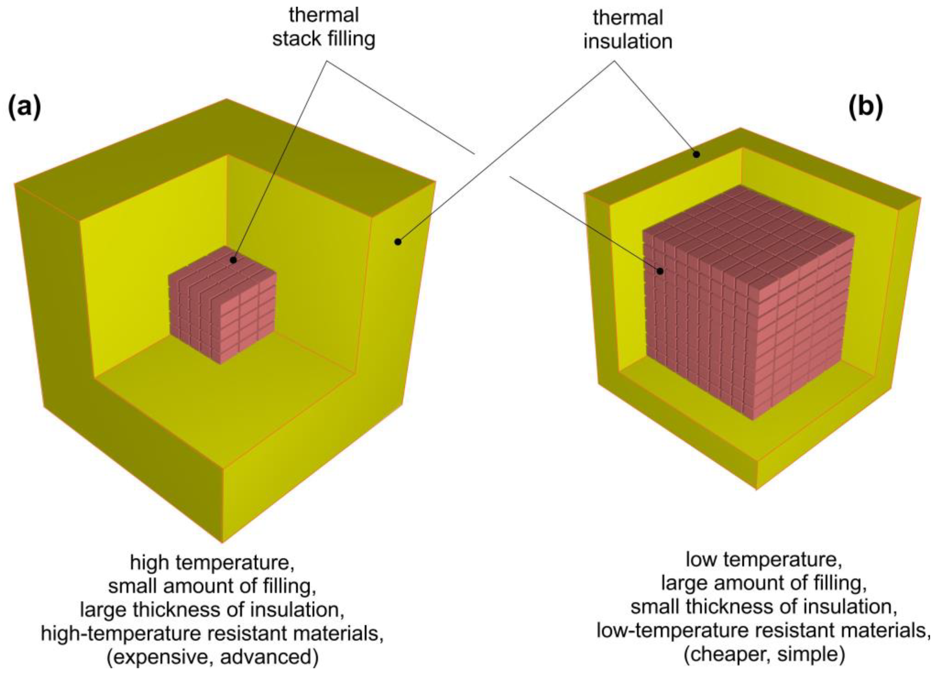
The energy analyses implemented by the authors in their previous publication [19] were carried out with many assumptions, including the maximum temperature of the bed being 600 °C and the filling of the storage stack being high-temperature resistant magnesia blocks. However, it is not certain whether the adopted assumptions allowed the authors to obtain optimal results. Assuming, for the purpose of the thermal comfort balance, that the same amount of heat should be accumulated regardless of the adopted maximum temperature and filling material, the two opposite variants presented in Figure 3 will be considered. Increasing the maximum temperature of the thermal stack allows more heat to be stored with the same amount or volume of used filling. However, the thermal stack needs to be resistant to such high temperatures. As the maximum temperature of the thermal stack increases, the necessary thickness of the thermal insulation also increases. In this situation, for a certain amount of the required heat of the thermal stack, a higher temperature of the thermal stack allows the size of the stack to be reduced, while the thickness, and, thus, the volume of the thermal insulation, are increased (see Figure 3a). At the same time, a higher temperature means that it is necessary to use more expensive temperature-resistant materials. In turn, a lower thermal stack temperature means that a smaller size of the storage stack, as well as a reduced thickness of thermal insulation, is needed (see Figure 3b). Moreover, cheaper materials can be used, as they are more easily available. In order to find the right solution, it was decided to review the available thermal stack filling materials and thermal insulation materials that are available when using modern construction technologies in Poland. By knowing which materials can be used, an analysis of the size and cost of the materials of the thermal storage (with the necessary heat capacity for the assumed maximum temperature, filling of the stack, and the stack’s thermal insulation) will be conducted.
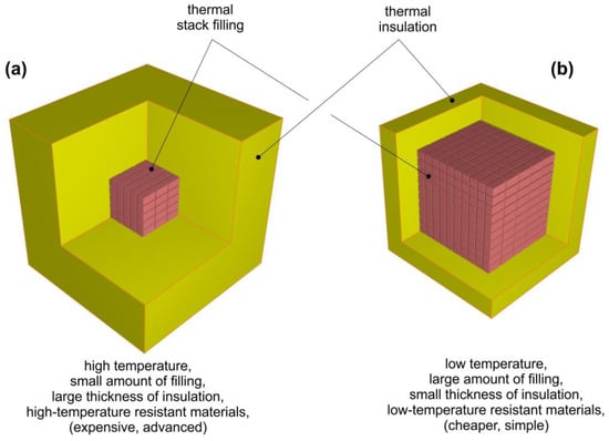
Figure 3.
Two opposing thermal storage stacks with insulation: (a) high-temperature, (b) low-temperature.
2. Materials and Methods
2.1. Thermal Stack Filling Materials
In the modern construction industry, there are many building materials that can be used as filling materials for thermal storage stacks. For the purpose of the study, a review of readily available building materials that can be applied in storage stacks was carried out. Building materials such as bricks/blocks have regular, rectangular shapes, which means that they can be arranged in stable stacks. For this reason, the stack casing does not have to have a high resistance to the lateral pressures of the filling. By leaving small gaps in the stack between the bricks/blocks for air to flow, it is relatively easy to organize heat exchange between the stack and the air. Bulk materials, such as gravel, crushed granite, or basalt pieces, require the use of gabion-type containers, into which they can be poured. The poured stones leave 30–40% free space, which can then be used for air, i.e., a heat carrier. The walls of the container must be resistant to the relatively high lateral pressures of the stones. Detailed technical and economic data for each of the considered filling materials are given in Table 1.

Table 1.
Building materials considered for filling thermal stack.
The following building materials were found to be applicable:
- Calcium silicate bricks are a relatively new material [28]. They are made by mixing quartz sand and quicklime with the addition of water. The bricks, after being formed into specific dimensions, were heated to a temperature of 200 °C using steam for several hours, which, in turn, accelerated the bonding of the lime with the sand.
- Ceramic bricks are the most known historical building material [29]. They are made from locally mined clays, which, after being mixed into a uniform mass, are formed into blocks of specific sizes and then dried. Depending on the type of clay, they are fired at temperatures of 850–1000 °C. Ceramic bricks are a durable material (lasting hundreds or even thousands of years), as long as they do not soak up water and freeze.
- Hollow ceramic blocks are a relatively new building material. They are much larger than bricks, but have a slotted structure, thanks to which they provide some thermal insulation. They are created in the same way as ceramic bricks. In the case of a thermal stack, these channels can be used as additional heat exchange surfaces.
- Clinker bricks are made in the same way as ceramic bricks, albeit using specially selected types of clay and through firing at a temperature of 1000–1100 °C. Bricks of this type are relatively resistant to water absorption, and for this reason, they are used for the facades of buildings.
- Clinker-perforated bricks are made in the same way as clinker bricks; however, they contain empty channels inside, which allow for their mass to be reduced. In the case of a thermal stack, these channels can be used as additional heat transfer surfaces.
- Chamotte bricks are made in the same way as ceramic bricks, albeit using selected types of refractory clay and through firing at a temperature of 1100–1300 °C. Bricks of this type are used for heat-resistant walls and vaults inside furnaces and boilers. They can even work at temperatures of up to 1500 °C.
- Chamotte half-thickness bricks are used for thin-walled heat-resistant linings in the interiors of furnaces and boilers for operating temperatures of up to 1800 °C.
- Magnesite blocks are not made of clay, instead being made of magnesium carbonate. This make-up means that they have a high density (the highest of all ceramic materials). At the same time, these products are very resistant to high temperatures, though they are expensive. They are quite chemically resistant, which is why they are used in industry as heat regenerators and high-temperature heat accumulators up to 650 °C.
- Concrete blocks are much larger than bricks. They are a relatively cheap building material [30] and are made by mixing aggregate, sand, cement, and water. After hardening, they are quite resistant to water absorption, which is why they are used for constructing underground building structures.
- Heat-resistant concrete [31] is only a dry mass, which, after adding water, allows for any shape to be cast in molds. There are no ready-made products produced from this material. Its composition is similar to ordinary concrete, though there is an addition of basalt and diabase, which, in turn, increases its fire resistance. Depending on the type of additive, concretes of this type are resistant to temperatures of up to 1000–1350 °C.
- Gravel is made of small round-shaped stones extracted from the beds of rivers. As they contain various types of rocks, including easily disintegrating ones, they cannot be heated to temperatures of above 400 °C. They cannot be stacked, and can only be poured into a container (filling about 60% of its volume). This structure enables air to flow through the free space.
- Granite crushed stone is widely used in the construction industry to harden soils under buildings and roads; it is also used as a component of concrete mixes. Granite is a stone that is resistant to temperatures of up to 800 °C, though after many heating cycles, it may crack. Crushed stone is polygonal in shape, cannot be stacked, and can only be poured into a container (filling about 65% of its volume). These features enable air to flow through the free space.
- Basalt crushed stone is used in the construction industry as a stone that does not absorb water. It is a stone that is resistant to temperatures of up to 400 °C, though after many heating cycles, it may crack. It is a stone melted in furnaces and then crushed into pieces. Basalt crushed stone has a shape close to rectangular, though pieces are often of different sizes. For this reason, it cannot be stacked, and can only be poured into a container (filling approximately 65% of its volume). This make-up enables air to flow through the free space.
In the case of bricks and blocks, it was assumed that for the purpose of air flow and heat exchange in the storage stack, it is necessary to maintain a certain distance between the individual elements of the filling. In the case of bricks, the necessary distance is 1 cm, while in the case of chamotte half-brick, it is 0.5 cm. For magnetite block and concrete block, the required distance is 2 cm, while for hollow block, it is 1 cm. These statistics are shown in Figure 4. This distance is an important parameter for determining the stack filling density (presented in Table 1).

Figure 4.
Schemes of how to fill a thermal stack.
2.2. Thermal Insulation Materials
Thermal insulation were divided into categories depending on their temperature ranges. The categories are as follows [32]:
- Low-temperature thermal insulation (usually cryogenic up to 15 °C),
- Intermediate-temperature thermal insulation (ranges from 16 to 300 °C),
- High-temperature thermal insulation (from 300 °C and above).
In the next part of the article, only high-temperature materials will be considered.
Good thermal insulation is generally characterized by low thermal conductivity. This value is often indicated by λ, W/m.K. Insulation is produced in different forms depending on the required application. These forms, amongst others, include the following options [33]:
- Foams (these could be either rigid or sprayed foams);
- Rigid boards;
- Sheets/mats/blankets (batts and rolls);
- Pre-formed shapes;
- Cements;
- Reflective insulation (typically aluminum foil covered surfaces);
- Loose-fill insulation (such as perlite granules).
Insulative materials are also divided into three types depending on their internal structure. They can be fibrous, cellular, or granular (loose-fill). Selected high-temperature thermal insulation materials are further discussed in the paragraphs below.
- Perlite is created as a result of heating rock pellets between temperatures of 800 and 1200 °C until they pop and produce small-sized, almost weightless pellets. Perlite is mainly composed of silica and aluminum, though it also contains some impurities. The thermal conductivity of perlite is about 0.076 W/m.K, falling to 0.057 W/m.K for expanded perlite, and its average density is about 120 kg/m3. Perlite is generally not advisable for use in applications with high probability of moisture permeability as perlite easily absorbs moisture; however, it is a favorable choice for filling small compact spaces and awkwardly-shaped areas, because of its loose-fill form. Perlite is usually classified as non-combustible. It is subject to dusting during installation; thus, appropriate caution should be taken [34,35].
- Mineral wool is a general term that often refers to three kinds of insulation material [35,36,37]:
- -
- Slag wool, which is made from blast furnace slag often sourced from steel mills;
- -
- Glass wool, which is fiber glass made from molten glass comprising 20–75% recycled glass. Its thermal conductivity is about 0.035 W/m.K, with a density ranging from 10 to 80 kg/m3. It is non-combustible and absorbs sound;
- -
- Rock mineral wool, which is usually obtained through either heating molten basalt or diabase to temperatures as high as 1600 °C, or spinning molten rock in a candy floss-like spinning machine. Its thermal conductivity is about 0.033 W/m.K, and it has a working temperature of between −200 and 900 °C. It is non-combustible.
Mineral wool usually comes in blanket or loose-fill forms. It absorbs moisture, but can be tempered with mineral oil to reduce its moisture-permeability.
- Aerogel is a super insulating material with high porosity, very low density, and high thermal insulation efficiency. It is created by replacing the liquid component of gel with gas, which is what makes it a good thermal insulator as gases are poor conductors. However, they are also poor radiative insulators because infrared radiation passes through them. Aerogels can be made from different compounds and can be organic or inorganic. The most popular forms of aerogels are silica aerogels, which come in blanket, powder, loose-fill, or monolithic form. The blankets have low thermal conductivity of about 0.015 W/m·K [37,38].
- Fiber glass is usually manufactured in several forms, including the following: mat/blanket (batts and rolls), rigid boards, and loose-fill form; therefore, its range of application is wide. It is produced through spinning molten glass (a large percentage is generated via recycling) into fibers. Due to the presence of glass particles in this material, it could be harmful when in contact with the human skin or eyes, or if ingested. It is moisture-permeable but fire-resistant. Its thermal conductivity also varies with respect to density in the case of batts or boards. Fiber glass is usually very affordable [37,39,40].
- Ceramic or refractory ceramic fibers are composed of equal proportions of alumina and silica. They are often referred to in modern terms as high-temperature insulation wool. Ceramic fibers come in two types: ceramic oxide fibers and ceramic non-oxide fibers. The latter fibers have the disadvantage of being resistant to oxidation. They are non-flammable, have low density, and possess high temperature capacity for continuous use up to 1260 °C. They generally come in blanket forms, although they can also be produced as pre-cast shapes depending on the desired application [32]. Polycrystalline wool is a kind of ceramic oxide fiber consisting of above 63% Al2O3 and 37% SiO2, with a continuous temperature rating of about 1650 °C and density ranging from 96 to 160 kg/m3 [41].
- Calcium silicate is a moisture-permeable insulation material that mainly contains hydrous calcium silicate. It is non-flammable. It has a thermal conductivity of about 0.054 W/mK and a density of 240 kg/m3. The maximum temperature recommended for continuous use is around 1000 °C [32,36].
For the purpose of further analyses, selected insulation materials are listed in Table 2.

Table 2.
Materials considered for thermal insulation of thermal stack.
2.3. Thermal Stack Variants
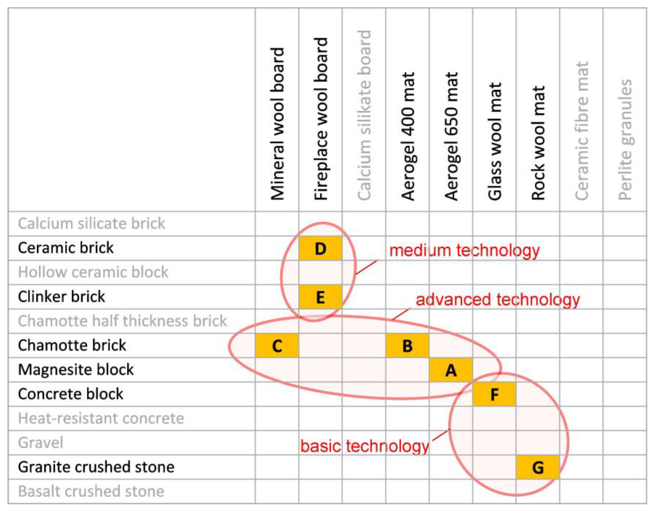
For the purpose of the study, the authors considered 12 possible thermal stack filling materials (Table 1) and 9 thermal insulation materials (Table 2), which, in total, gives as many as 12 × 9 = 108 possible thermal stack construction variants. It was assumed that this figure represents an excessive number of combinations, and, in practice, it is more reasonable to propose just seven versions, which are marked with the letters A to G. These versions were arranged so that variants A, B, and C are the most technologically advanced variants (in terms of used materials). Variants D and E use medium range technology, while variants F and G are the simplest versions because they are made of the most readily available and cheapest materials. The matrix of the considered variants A–G is shown in Figure 5 and described in Table 3.
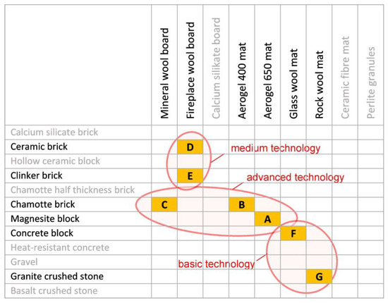
Figure 5.
Matrix of considered variants A–G with a marked choice of material for stack’s filling and thermal insulation.

Table 3.
Considered versions of cooperating pairs of materials for thermal stack.
The materials marked in Figure 5 with gray text color were withdrawn from further tests after the first attempts at calculations; these materials are as follows:
- building materials with excessively low densities, for which the necessary volume of the thermal stack filling would have to be extremely large,
- insulation materials with high thermal conductivity coefficients, for which the necessary volume of the thermal insulation would also have to be very large.
These materials were not considered in further analyses.
2.4. Heat Loses from the Stack
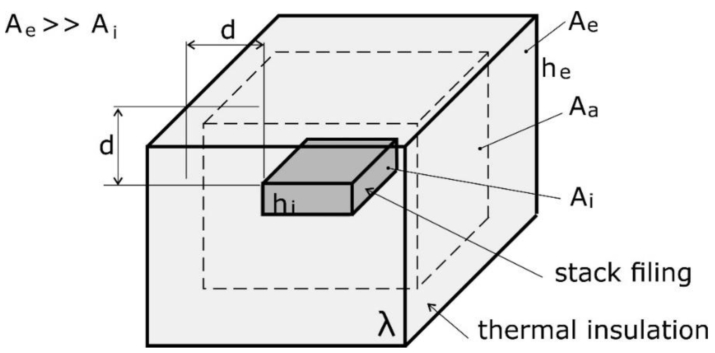
Each type of storage stack requires the use of thermal insulation in order to avoid losing stored heat. Stacks with a high temperature and a long period of heat storage require exceptionally thick insulation—both of these criteria are met by the stack that was considered in the case of a low-energy house with a seasonal storage stack. Typical applications of thermal insulation usually concern situations where the thickness of the insulation is much smaller than the dimensions of the insulated device. Calculations of heat flow are. thus, relatively simple, as they refer to flat or curved surfaces. In the analyzed case, it is necessary that heat losses forming the stack do not exceed 500 W (theoretically, higher heat loss values could be accepted, though in autumn—when the stack has the highest temperature—such high values would require the use of air conditioning, even at low ambient temperatures). For this reason, the used thermal insulation should be quite thick. In such cases, as shown in Figure 6, the outer surface of the stack’s insulation Ae exceeds the outer surface of the stack’s filling Ai several times.
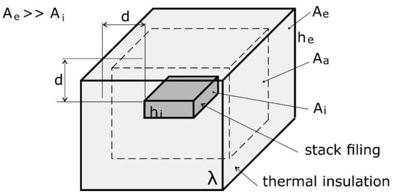
Figure 6.
Scheme of calculating heat losses from stack through insulation.
In the literature, we find fundamental calculations of heat transfer for large, flat, and boundary-less surfaces that are utilized in arbitrarily calculating thick layers of thermal insulation. There are also widely known formulae for calculating heat transfer in insulated pipes and spheres. However, considering this case with thick layers of insulation, the situation is similar to the case of the insulated sphere, although the geometry here is of a rectangular shape where we have Ae >> Ai. In regard to the calculation of heat transfer for cylindrical or spherical surfaces, the convection coefficient, which influences the rate of convection, is increased on the external side and decreased on the internal side. This increment or reduction is performed in proportion to the ratio of the areas considered.
For such defined conditions of heat transfer, the following formula was used:
where:
- Q—heat loss, W;
- Ae—external area of thermal insulation, m2;
- Ai—internal area of thermal insulation (external area of storage stack), m2;
- Aa—average area of thermal insulation, m2;
- d—thickness of thermal insulation, the same in each direction, m;
- λ—heat conduction coefficient, W/mK;
- he—external convective heat transfer coefficient, W/m2K;
- hi—internal convective heat transfer coefficient, W/m2K;
- ΔT—temperature difference between external and internal air, °C.
In Figure 5, the average heat exchange surface is marked with a dashed line. When the area Ae is close to Ai, which is most often the case in technical issues, the average area Aa can be calculated as the arithmetic mean:
In the case where the area Ae is much larger than Ai, the average area Aa should be calculated as the arithmetic mean:
The value of the heat conduction coefficient strongly depends on temperature. Usually, in the temperature range from 20 to 600 °C, it increases twice. In such a case, the inner layers of the stack’s insulation would have a higher value for this coefficient, whereas the outer layers would have a lower value. In order to use one value in the calculations, it was proposed that a weighted average that is proportional to the layer area would be calculated:
where:
- λe—heat conduction coefficient for the temperature of an external layer, W/mK;
- λi—heat conduction coefficient for the temperature of an internal layer, W/mK.
In comparison to the heat transfer calculation for cylindrical or spherical surfaces, the thermal conductivity coefficient on the side with the larger area i.e., the external side, is increased, while that on the smaller internal area is reduced. This increment or reduction is performed in proportion to ratio of the areas given consideration.
In order to simplify the calculations, it was assumed that the structure of the insulation is uniform in the entire volume (especially at the bottom). The real construction of the thermal stack should take into account the strength of the thermal insulation material pressed under the weight of the stack’s filling material. Typically, the compressive strength of thermal insulation materials is low, and the construction would require a steel support frame to support the stack filling. Analyses of this kind would exceed the possibilities of a single publication, which is why the authors adopted the assumptions involved in simplifying the considerations.
2.5. Mathematical Modelling of the System
In the previous publication [19], the authors described the construction and operation of a mathematical model that was used to assess the energy processes that occur in the analyzed single-family house. This model takes into account the following aspects: heat flow through the walls, windows, doors, floor and roof of the building; solar radiation gains through the windows; and ventilation with the use of a heat recovery unit. The installation was powered using a set of 39 photovoltaic panels located on the roof of the building. For the needs of the current analyses, the section for changing the thermal stack’s parameters was expanded in the model (see Figure 7, indicated in pink), in turn giving the possibility of introducing different thermal stack sizes, as well as the use of different materials for the stack’s filling and thermal insulation. These analyses were carried out, using the trial and error method, within the temperature ranges in which the materials can be used as stack filling or thermal insulation.

Figure 7.
Calculation algorithm scheme: preliminary and precise energy balance calculations with correction loops.
By selecting any combination of variant and temperature of the stack, it is necessary that heat losses from the stack fall between 400 and 500 W. The lower limit of 400 W is necessary to avoid having to use excessive amounts of insulation. The higher limit, i.e., 500 W, is necessary to avoid overheating the living space. The thermal stack ought to have residual energy load up to 15 May, ensuring constant heating potential throughout the heating season (from 15 September to 15 May). If the energy load of the stack is too high by 15 May, repeated calculations are made to reduce the dimensions of the stack filling, while if it is too low, the dimensions of the stack filling should be increased.
3. Results
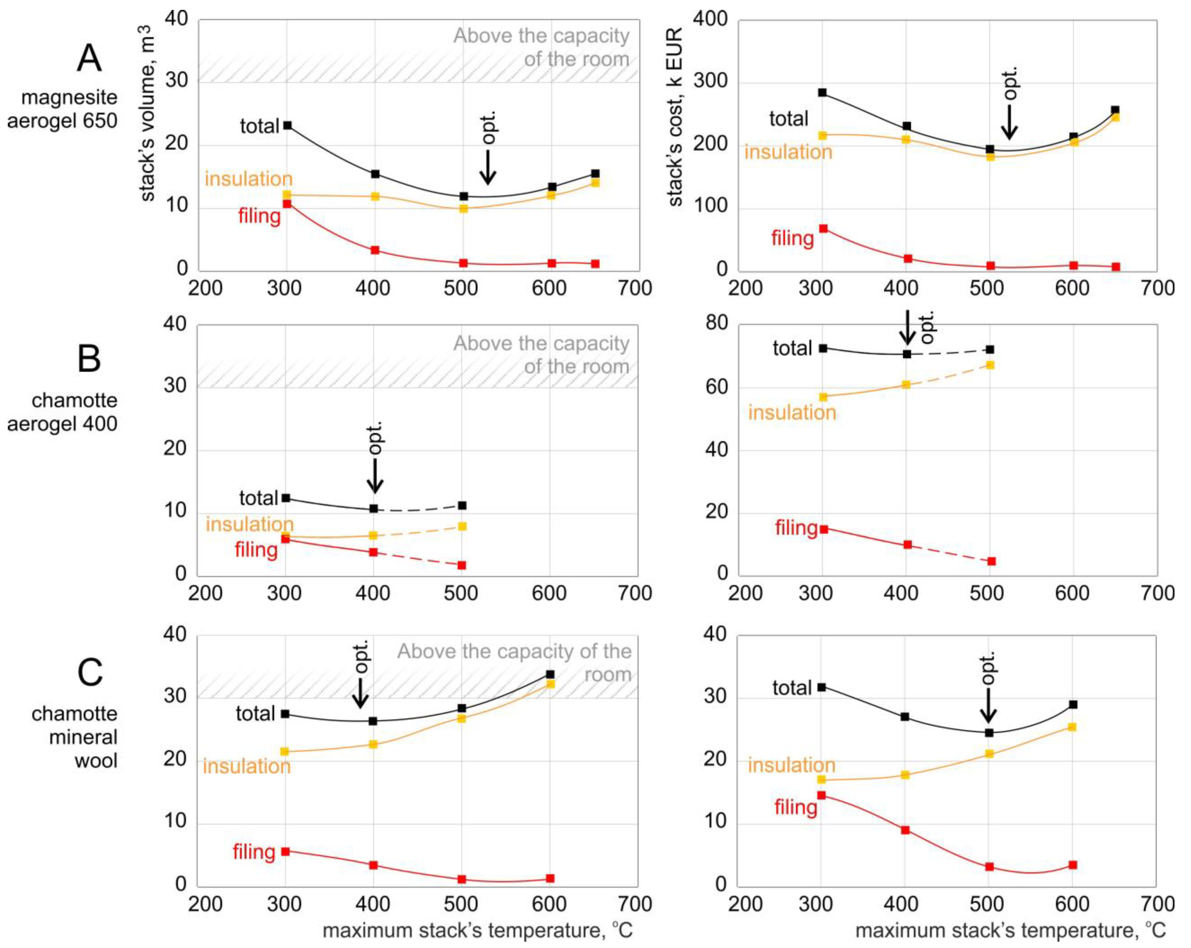
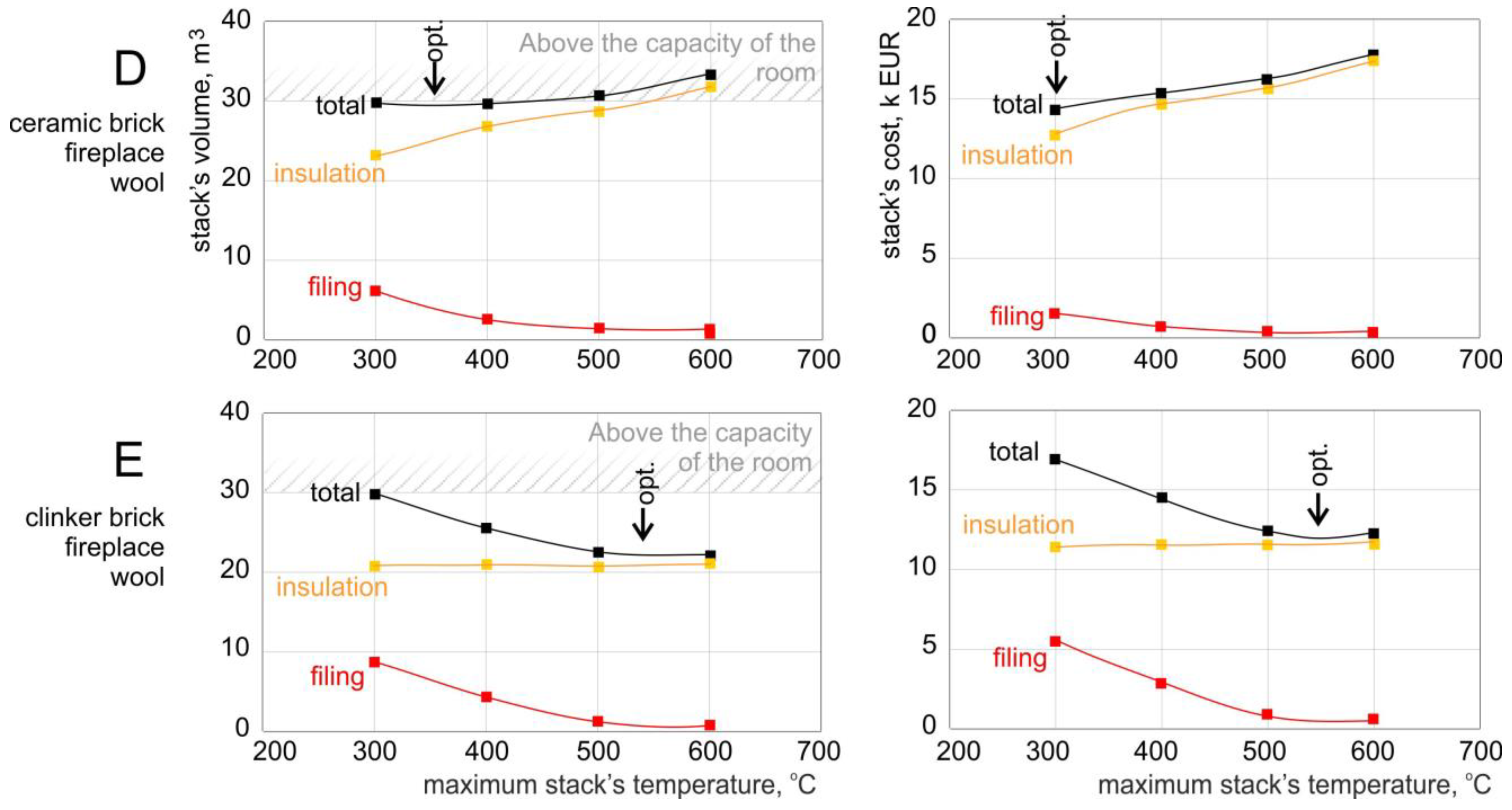
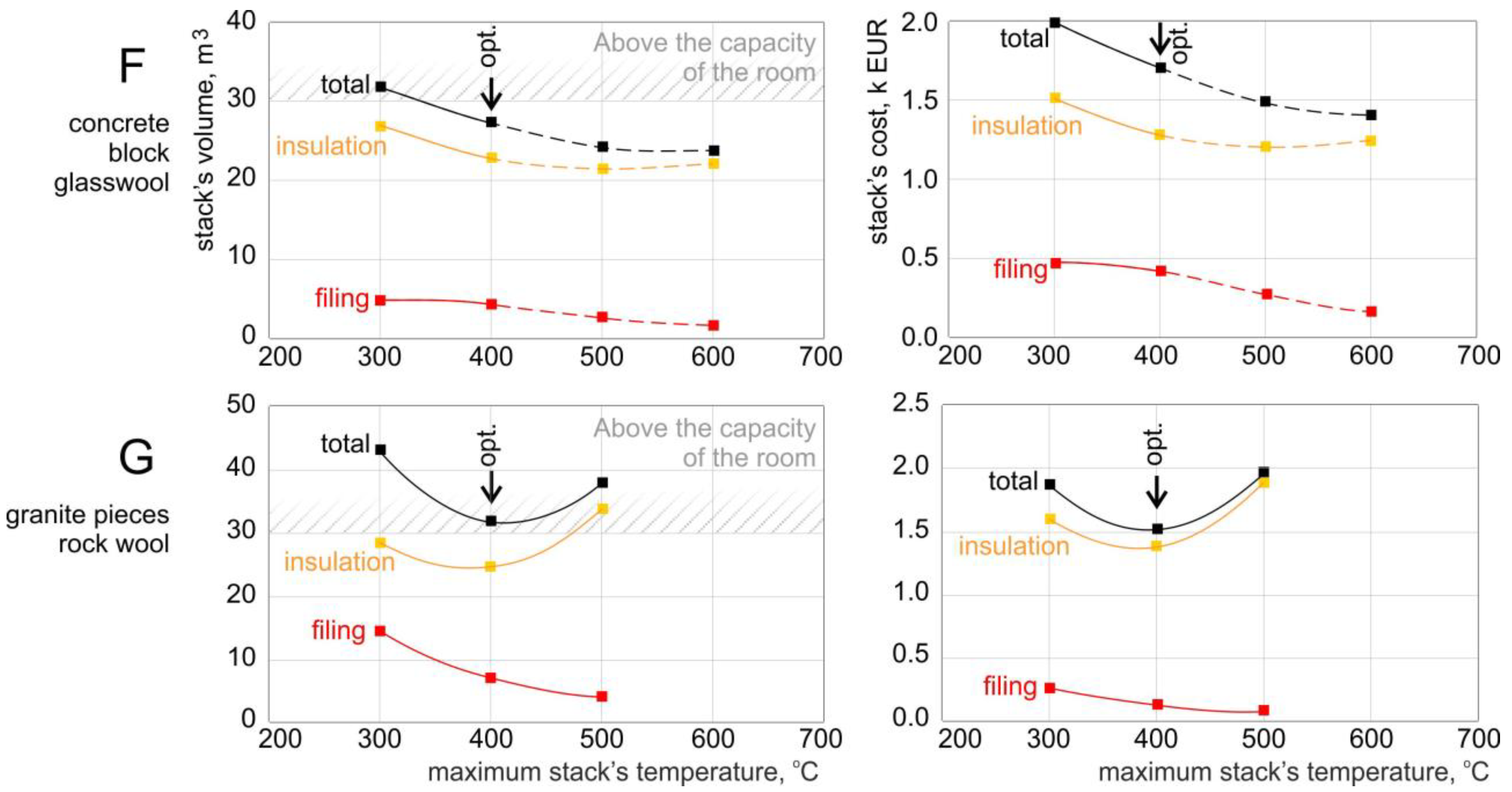
Using the mathematical model of energy balancing for the entirety of the analyzed building, a series of calculations was made for all seven considered variants of the thermal storage construction. For each variant, the calculations were carried out for several values of the maximum temperature of the stack’s filling—usually with a step of 100 °C. For some variants, the calculations were carried out for lower temperatures, because the used stack’s filling or thermal insulation materials were not resistant to such high temperatures. To clarify, temperatures that are not recommended are marked with a dashed line (see Figures 8B and 10F). The graphs were compiled in pairs for each of the variants. The left graph shows the volume of the thermal stack (total volume in black), the volume of the stack’s filling (in red), and the volume of the stack’s insulation (in yellow). In addition, the upper part of the graph above 30 m3 was hatched diagonally, because this section represents the maximum volume of the room that is intended to be filled with the thermal storage. The right graph shows the costs of the thermal storage material (in the same color scheme). We note that all graphs of the thermal storage’s volume have the same scale on the vertical axis of 0–40 m3 (only graph G has a scale of 0–50 m3). In turn, the cost graphs have individual scales that vary greatly. For example, the scale for variant A is 0–400,000 EUR, while for variant F, it is only 0–2000 EUR. Different scales were chosen in order to facilitate the finding of the point of the minimum costs.
Figure 8 shows the results of the analyses for variants A, B, and C (advanced technology). It can be seen that with an increase in the maximum allowable working temperature of the stack, the volume of its filling decreases, while the amount of thermal insulation increases. For each of the considered variants A, B, and C, the cost of the stack filling is always lower than the cost of the thermal insulation. It is usually several times lower, and it is only in the case of variant C (chamotte + mineral wool) that the costs are similar, but this fact is only true for the maximum temperature of 300 °C.
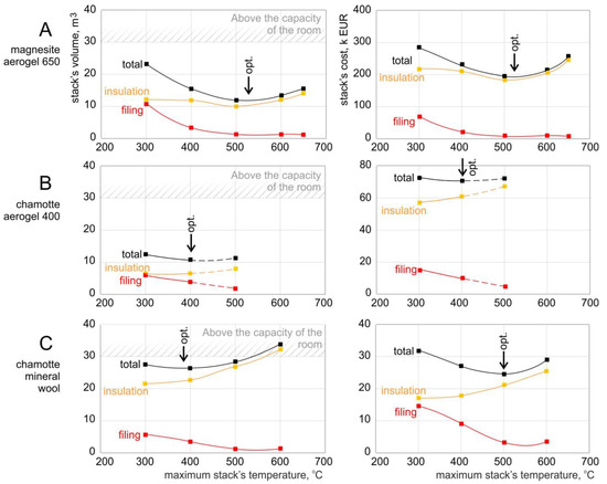
Figure 8.
Calculation results for variants A, B, C (advanced technology): (A) version A, (B) version B, (C) version C.
For variant B, the analyses carried out for the cases of above 400 °C are only theoretical, because the aerogel that was used as the thermal insulation should not work at such high temperatures.
For each of the considered variants, the minimum volume of the stack can be indicated. It is different for the different temperatures for each of the variants:
- for variant A, the minimum volume of the thermal storage is equal to 11.9 m3 for a temperature of 520 °C;
- for variant B, the minimum volume of the thermal storage is equal to 10.9 m3 for a temperature of 400 °C;
- for variant C, the minimum volume of the thermal storage is equal to 27 m3 for a temperature of 390 °C.
For each of the considered variants, the minimum cost of the storage stack can be indicated. It is different for the different temperatures for each of the variants:
- for variant A, the minimum cost is EUR 190,000 for a temperature of 520 °C;
- for variant B, the minimum cost is EUR 70,000 for a temperature of 400 °C;
- for variant C, the minimum cost is EUR 24,000 for a temperature of 500 °C.
In variants A and B, the optimal temperature required for the volume and cost of the storage stack is the same, whereas for variant C (chamotte and mineral wool), the optimal temperatures differ by as much as 110 °C.
The comparison between variants A and B shows that it would make more sense to use variant B, because it has a slightly smaller volume, while at the same time, it has much lower costs (2.7 times lower).
Figure 9 shows the results of the analyses for variants D and E (medium technology). In this case, it is visible that the volume of the stack’s filling decreases, whereas the amount of thermal insulation increases with the increase in the maximum allowable working temperature of the stack. For each of the considered variants D and E, the cost of the stack’s filling is always lower than the cost of the thermal insulation.
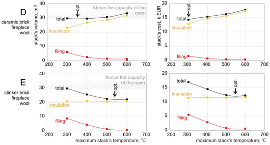
Figure 9.
Calculation results for variants D, E (medium technology): (D) version D, (E) version E.
For each of the considered variants, the minimum volume of the storage stack can be indicated. This value is different for the different temperatures for each of the variants:
- for variant D, the minimum volume of the thermal storage is equal to 29.8 m3 for the temperature of 350 °C;
- for variant E, the minimum volume of the thermal storage is equal to 23 m3 for the temperature of 540 °C.
For each of the considered variants, the minimum cost of the storage stack can be indicated. This value is different for the different temperatures for each of the variants:
- for variant D, the minimum cost is equal to EUR 14,500 for the temperature of 300 °C;
- for variant E, the minimum cost is equal to EUR 12,500 for the temperature of 550 °C.
In both variants, the optimal temperature required for the volume and the cost of the storage stack is the same; it is only different for variant D (by 50 °C).
Figure 10 shows the results of the analyses for variants D and E (simple technology). In this case, it is clear that the volume of the stack’s filling decreases, whereas the amount of thermal insulation increases with an increase in the maximum allowable working temperature of the storage stack. For each of the considered variants F and G, the cost of the stack’s filling is always lower than the cost of the thermal insulation. For variant F, the analyses carried out in the cases above 400 °C are only theoretical, because the glasswool used as thermal insulation should not work at such high temperatures.
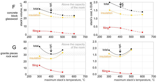
Figure 10.
Calculation results for versions F, G (simple technology): (F) version F, (G) version G.
For each of the considered variants, the minimum volume of the storage stack can be indicated. This value is different for the different temperatures for each of the variants:
- for variant F, the minimum volume of the thermal storage is equal to 27 m3 for the temperature of 400 °C;
- for variant G, the minimum volume of the thermal storage is equal to 32 m3 for the temperature of 400 °C.
For each of the considered variants, the minimum cost of the storage stack can be indicated. This value is different for the different temperatures for each of the variants:
- for variant F, the minimum cost is EUR 1700 for the temperature of 400 °C;
- for variant G, the minimum cost is EUR 1500 for the temperature of 400 °C.
In both variants, the optimal temperature required for the volume and the cost of the storage stack is the same.
4. Discussion
Table 4 presents the thermal stack’s parameters for all the considered variants A–G for their optimal maximum operating temperature. It can be seen that the amount of exported energy is the same for all the variants, amounting to about 10.77–10.95 MWh during the whole year. This amount of energy could result in a gain of 2180 EUR/year. The constant value of this energy results from the constant amount of thermal energy that is required to heat the living space, which is independent of the materials that were used to build the stack.

Table 4.
Parameters of thermal stack for selected optimal maximum operating temperature in case of all considered variants.
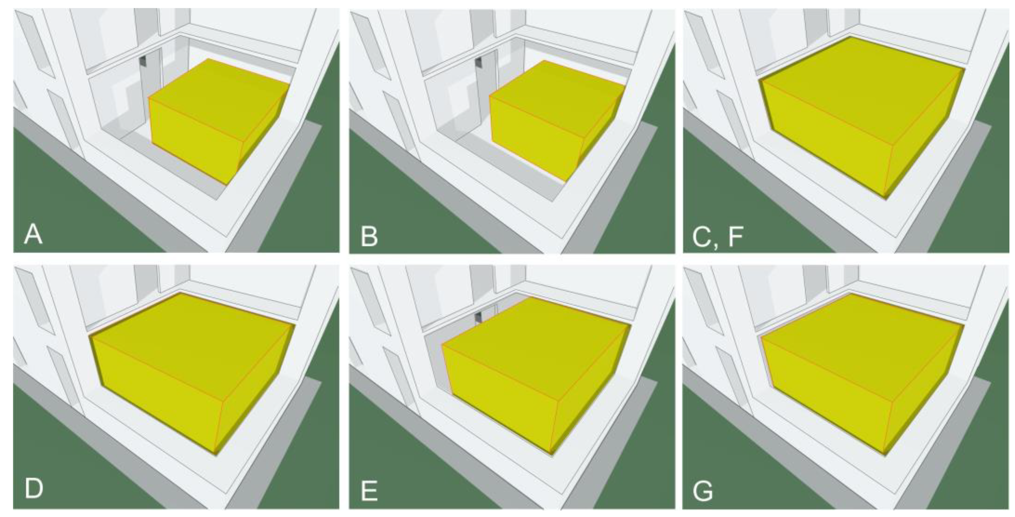
The results presented in the form of a table were also converted to graphical form, as shown in Figure 11. When comparing the results, the group of variants A–C (advanced) was considered to be unreasonably expensive. Among variants D and E (medium), variant E (clinker brick and fireplace wool), with a volume of 23 m3 and a cost of EUR 12,500, was considered to be worth recommending. Among variants F and G (simple), variant F (concrete block and glass wool), with a volume of 27 m3 and a cost of EUR 1700, was considered to be worth recommending. To clarify these points, the recommended variants E and F are marked in pink in Figure 11. Figure 12 shows a cross-sectional view of the house for each variant of the stack’s insulation dimensions. As can be seen, even the smallest stack (variant B) does not significantly increase the usable living space.

Figure 11.
Bar chart presentation of thermal stack’s parameters for all considered variants at optimal temperature.
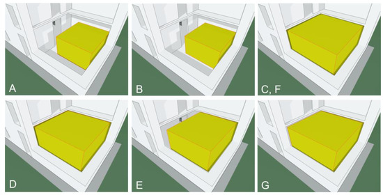
Figure 12.
Cross-sectional view of house for each variants of stack’s insulation: (A) version A, (B) version B, (C) version C, (D) version D, (E) version E, (F) version F, (G) version G.
4.1. Technological Comments
According to the calculation results, the following comments can be made:
- Filling materials with densities lower than 1500 kg/m3 are not recommended for such high-temperature seasonal thermal storage applications to avoid creating excessively large dimensions for the stack. Insulation materials with coefficients of thermal conductivity higher than 0.05 W/m·K would also result in unnecessarily large insulation thickness.
- For each of the considered variants, the cost of the stack’s filling is always lower than the cost of the thermal insulation. It is usually several times lower, and it is only in variant C (chamotte and mineral wool) that the costs of the materials are similar (with the maximum temperature being limited to 300 °C).
- In the advanced variants A (magnesite and aerogel 650) and B (chamotte and aerogel 400), the volume of the thermal stack is 11.9 m3 and 10.9 m3, respectively, which is much smaller than the size of the room for which it is intended (30 m3). For the C–G variants, the volume of the thermal stack is slightly smaller than the volume of the room. For variant G only (granite pieces and rockwool), this volume is 31 m3—thus, it slightly exceeds the size of the room.
- All of the variants differ greatly in terms of the thermal stack’s cost. The most expensive are the advanced variants, because the cost of variant A (magnesite and aerogel 650) is equal to EUR 190,000 for a maximum temperature of 520 °C, and its value probably exceeds the cost of building a single-family house. Variant B (chamotte and aerogel 400) costs EUR 70,000 for a maximum temperature of 400 °C, which makes it 1.7 times cheaper than variant A. The two cheapest variants are F (concrete block and glasswool), with a cost of EUR 1720, and G (granite pieces and rock wool), with a cost of EUR 1500—both variants function for a maximum temperature of 400 °C.
- The advanced variants were considered to be unreasonably expensive. Among the medium technology variants, variant E (clinker brick and fireplace wool), with a volume of 23 m3 and a cost of EUR 12,500, was considered to be worth recommending. In turn, among the simple technology variants, variant F (concrete block and glass wool), with a volume of 27 m3 and a cost of EUR 1700, was considered to be worth recommending.
4.2. Comparative Analyses
To correctly evaluate the significant value of the selected variants E and F, they can be compared to a water heat storage system, shown seen in Table 5.

Table 5.
Selected features of variants E and F, compared to alternative heat storage in water tanks.
In the case of the considered building, storage of about 8TJ of heat per annum is required to ensure and maintain the thermal comfort of the occupants. Variant E (filled with clinker bricks) and variant F (filled with concrete blocks) were previously assessed for the production of this amount of heat. However, to load the same amount of heat, which is stored in water tanks with a 27 m3 volume of water, when operating between 30 and 100 °C, it would be necessary to have the same or even a slightly larger volume reservoir, i.e., about 30 m3, as indicated in Table 6.

Table 6.
Selected features of energy storage technologies.
Comparing the costs of heat storage in water tanks and the two variants of heat storage selected, the cost of a typical water tank system is about 2.3 times more expensive than variant E and, staggeringly, about 17 times more expensive in the case of variant F.
The cost-friendliness of variants E and F also make a huge difference in comparison to electric battery storage (see Table 6), which costs almost 1000 times as much as concrete filling in the case of NiMH batteries, or about 400 times as much in the case of Li-ion batteries.
According to the selected part of proposed HVAC-PVPSTS system, the cost of building of the house increases, as presented in Table 7. The base cost of storage stack recommended by the authors increases the cost of building the house by only about 2–11%, according to the technology employed. Implementing the complete HVAC-PVPSTS system would only increase the cost of building a typical home in Poland by about 20%, which is reasonable and even attractive in comparison to other heat storage technologies. In Poland, the materials considered are readily available and accessible in the local market.

Table 7.
Selected costs of analyzed plus-energy house.
5. Conclusions
The article considers multiple variants of the thermal storage construction, which can be used to meet the needs of a plus-energy single-family house powered using a set of PV panels that cover the entire roof. Using the mathematical model, which describes the energy processes occurring in the building and in HVAC installation, seven sets of materials for the construction of the thermal storage were analyzed. These sets are technologies divided into the following categories: three advanced, two medium, and two basic technologies. For each variant, calculations were made that assumed several values of the maximum level of the maximum temperature of the stack (according to the thermal resistance of these materials). The following key findings can be drawn:
- As the maximum allowable working temperature of the storage stack increases, the amount of the stack’s filling material decreases, with the amount of thermal insulation material also increasing.
- The higher the density of the thermal filling material, the smaller the required thermal stack volume. Low-density materials, such as ceramic brick or ceramic hollow block, should not be used because the thermal stack would have to have a huge volume.
- For each of the considered variants, the minimum volume of the storage stack can be indicated. It occurs at a different temperature for each of the variants. The minimum cost of the stack’s materials can also be indicated, which also occurs at a different temperature for each of the variants. In most of the variants, the optimal temperature with regards to the volume and the cost of the stack is usually the same.
- There is a huge range (>100) of costs between the considered variants of the construction of the same storage stack.
- Seasonal thermal storage based on a sensible heat storage stack filled with building materials is currently not popular in thermal storage technologies in comparison to heat storage in water tanks. The analysis revealed that a high-temperature storage stack filled with clinker bricks or concrete blocks may have a smaller volume than a comparable water storage tank with the same amount of stored heat.
- The costs of heat storage in a stack filled with the materials proposed by the authors is considerably cheaper than the cost of heat storage in the much more popularized water tank systems. In the case of a thermal storage stack filled with clinker bricks, it is about 2.3 times cheaper and, more significantly, 17 times cheaper in the case of a thermal storage stack filled with concrete blocks.
- The basic cost of the storage stack recommended by the authors would increase the building cost of the house by only about 2–11%, according to the technology used. Applying the complete HVAC-PVPSTS system would increase the cost of building the house by about 20%, which is not a problematic figure.
- Seasonal thermal storage based on sensible heat filled with building materials offers some advantages, such as non-toxicity, non-flammability, corrosion resistance, and being the most environmentally and human health-friendly material. Additionally, sensible heat materials are readily available and accessible in the local market.
Author Contributions
Conceptualization, J.K.; methodology, J.K.; software, J.K. and O.O.; formal analysis, J.K.; investigation, J.K. and O.O.; resources, J.K. and O.O.; data curation, J.K. and O.O.; writing—original draft preparation, J.K. and O.O.; Writing—review and editing, J.K.; visualization, J.K.; supervision, J.K.; project administration, J.K.; funding acquisition, J.K. All authors have read and agreed to the published version of the manuscript.
Funding
This research was funded by Wroclaw University of Science and Technology (Project No. 8211104160).
Data Availability Statement
The relevant data underlying this study are fully available under the details provided in the references. For further questions, please contact the corresponding author.
Conflicts of Interest
The authors declare no conflict of interest.
References
- Eurostat. Energy Consumption in Households (2020 Data) 2022. Available online: https://ec.europa.eu/eurostat/web/products-eurostat-news/-/ddn-20220617-1 (accessed on 22 April 2023).
- Sabihuddin, S.; Kiprakis, A.E.; Mueller, M. A Numerical and Graphical Review of Energy Storage Technologies. Energies 2015, 8, 172–216. [Google Scholar] [CrossRef]
- Lanahan, L.; Tabares-Velasco, P.C. Seasonal Thermal-Energy Storage: A Critical Review on BTES Systems, Modeling, and System Design for Higher System Efficiency. Energies 2017, 10, 743. [Google Scholar] [CrossRef]
- Sarbu, I.; Sebarchievici, C. A Comprehensive Review of Thermal Energy Storage. Sustainability 2018, 10, 191. [Google Scholar] [CrossRef]
- Villasmil, W.; Fischer, L.J.; Worlitschek, J. A review and evaluation of thermal insulation materials and methods for thermal energy storage systems. Renew. Sustain. Energy Rev. 2019, 103, 71–84. [Google Scholar] [CrossRef]
- Aditya, L.; Mahlia, T.M.I.; Rismanchi, B.; Ng, H.M.; Hasan, M.H.; Metselaar, H.S.C.; Muraz, O.; Aditiya, H.B. A review on insulation materials for energy conservation in buildings. Renew. Sustain. Energy Rev. 2017, 73, 1352–1365. [Google Scholar] [CrossRef]
- Long, L.; Ye, H. The roles of thermal insulation and heat storage in the energy of the wall materials: A simulation study. Sci. Rep. 2016, 6, 24181. [Google Scholar] [CrossRef] [PubMed]
- Kumar, D.; Alam, M.; Doshi, A.J. Investigating the Influence of Thermal Conductivity and Thermal Storage of Lightweight Concrete Panels on the Energy and Thermal Comfort in Residential Buildings. Buildings 2023, 13, 720. [Google Scholar] [CrossRef]
- Akan, A.E. Determination and Modeling of Optimum Insulation Thickness for Thermal Insulation of Buildings in All City Centers of Turkey. Int. J. Thermophys. 2021, 42, 49. [Google Scholar] [CrossRef]
- Hugo, A.; Zmeureanu, R. Residential Solar-Based Seasonal Thermal Storage Systems in Cold Climates: Building Envelope and Thermal Storage. Energies 2012, 5, 3972–3985. [Google Scholar] [CrossRef]
- Park, B.; Srubar, W.V., III.; Krarti, M. Energy performance analysis of variable thermal resistance envelopes in residential buildings. Energy Build. 2015, 103, 317–325. [Google Scholar] [CrossRef]
- Nematchoua, M.; Raminosa, C.R.R.; Mamiharijaona, R.; Rene, T.; Orosa, J.A.; Meukam, P. Study of the economical and optimum thermal insulation thickness for buildings in a wet and hot tropical climate: Case of Cameroon. Renew. Sustain. Energy Rev. 2015, 50, 1192–1202. [Google Scholar] [CrossRef]
- Pazold, M.; Radon, J.; Kersken, M.; Künzel, H.; Antretter, F.; Sinnesbichler, H. Development and Verification of Novel Building Integrated Thermal Storage System Models. Energies 2023, 16, 2889. [Google Scholar] [CrossRef]
- Shrestha, S.S.; Tiwari, J.; Rai, A.; Hun, D.A.; Howard, D.; Desjarlais, A.O.; Francoeur, M.; Feng, T. Solid and gas thermal conductivity models improvement and validation in various porous insulation materials. Int. J. Therm. Sci. 2023, 187, 108164. [Google Scholar] [CrossRef]
- An, L.; Armstrong, J.N.; Hu, Y.; Huang, Y.; Li, Z.; Zhao, D.; Sokolow, J.; Guo, Z.; Zhou, C.; Ren, S. High temperature ceramic thermal insulation material. Nano Res. 2022, 15, 6662–6669. [Google Scholar] [CrossRef]
- Sugama, T.; Pyatina, T. Thermally Insulating, Thermal Shock Resistant Calcium Aluminate Phosphate Cement Composites for Reservoir Thermal Energy Storage. Materials 2022, 15, 6328. [Google Scholar] [CrossRef] [PubMed]
- Fuchs, B.; Hofbeck, K.; Faulstich, M. On vacuum insulated thermal storage. Energy Procedia 2012, 30, 255–259. [Google Scholar] [CrossRef]
- Fuchs, B.; Hofbeck, K.; Faulstich, M. Vacuum insulation panels—A promising solution for high insulated tanks. Energy Procedia 2012, 30, 424–427. [Google Scholar] [CrossRef]
- Kasperski, J.; Bać, A.; Oladipo, O. A Simulation of a Sustainable Plus-Energy House in Poland Equipped with a Photovoltaic Powered Seasonal Thermal Storage System. Sustainability 2023, 15, 3810. [Google Scholar] [CrossRef]
- Available online: https://www.leroymerlin.pl/materialy-budowlane/materialy-budowlane-stan-surowy/cegly-pustaki-i-bloczki-betonowe/cegla-pelna-silka-kl-20-26x12x6-5-cm,p614771,l345.html (accessed on 25 May 2023).
- Available online: https://www.castorama.pl/materialy-budowlane/cegly-bloczki-pustaki/cegly.cat (accessed on 25 May 2023).
- Available online: https://www.bricoman.pl/termoton-25-p-w-owczary-20152993.html?smile_retailer_id=5&gclid=EAIaIQobChMI5bvfi4iO_wIV9QCiAx0FMA1kEAQYAiABEgJ5MPD_BwE (accessed on 25 May 2023).
- Available online: https://www.castorama.pl/search?term=ceg%C5%82a+szamotowa (accessed on 25 May 2023).
- Available online: https://allegro.pl/oferta/piec-akumulacyjny-dimplex-xle050-dynamiczny-8169594991 (accessed on 25 May 2023).
- Available online: https://www.castorama.pl/search?category=CAPL_0000058&term=bloczek+betonowy (accessed on 25 May 2023).
- Available online: https://www.leroymerlin.pl/materialy-budowlane/zaprawy-i-tynki/zaprawy-murarskie/zaprawa-szamotowa-zsz-1-iii-10-kg,p480881,l358.html (accessed on 25 May 2023).
- Available online: http://wroclawskie-kruszywa.pl/cennik/ (accessed on 25 May 2023).
- Mehta, M.; Scarborough, W.; Armpriest, D. Building Construction: Principles, Materials, and Systems (What’s New in Trades & Technology); Pearson: London, UK, 2016. [Google Scholar]
- Borsoum, M.W. Fundamentals of Ceramics; CRC Press, Taylor and Francis Group: Boca Raton, FL, USA, 2020. [Google Scholar]
- Mehta, P.K.; Monteiro, P.J.M. Concrete Microstructure Properties and Materials (Mechanical Engineering); McGraw Hill: New York, NY, USA, 2013. [Google Scholar]
- Pimienta, P.; McNamee, R.J.; Mindeguia, J.C. Physical Properties and Behaviour of High-Performance Concrete at High Temperature; Springer: Berlin/Heidelberg, Germany, 2019. [Google Scholar]
- Insulation Materials and Properties. In Thermal Insulation Association of Canada Guidebook; Thermal Insulation Association of Canada: Ottawa, ON, Canada, 2013.
- Energy Saver. Office of Energy Efficiency and Renewable Energy, US Department of Energy. Types of Insulation. Available online: https://www.energy.gov/energysaver/types-insulation (accessed on 12 April 2023).
- Shawyer, M.; Medina Pizzali, A.F. Thermal Insulation Materials, Technical Characteristics and Selection Criteria—The Use of Ice on Small Fishing Vessels; FAO Fisheries Technical Paper; FAO: Rome, Italy, 2003. [Google Scholar]
- Energy Saver. Office of Energy Efficiency and Renewable Energy, US Department of Energy. Insulation Materials. Available online: https://www.energy.gov/energysaver/insulation-materials (accessed on 12 April 2023).
- Deshmukh, G.; Birwal, P.; Datir, R.; Patel, S. Thermal Insulation Materials: A Tool for Energy Conservation. J. Food Process. Technol. 2017, 8, 8–11. [Google Scholar] [CrossRef]
- Insulation Materials and their Thermal Properties. Greenspec. Available online: https://www.greenspec.co.uk/building-design/insulation-materials-thermal-properties/ (accessed on 12 April 2023).
- Vajó, B.; Lakatos, Á. Super Insulation Materials—An Application to Historical Buildings. Buildings 2021, 11, 525. [Google Scholar] [CrossRef]
- Thermal Insulation: Properties and Applications in Housing; Technical Manual; United Nations Industrial Development Organisation: Vienna, Austria, 2017.
- Kiron, M.I. Types, Properties, Production and Application of Ceramic Fiber. Textile Learner. Available online: https://textilelearner.net/ceramic-fiber-types-properties/ (accessed on 14 April 2023).
- Weinstein, J. An Overview of Refractory Ceramic Fibres. Thermal Processing. 2021. Available online: https://thermalprocessing.com/an-overview-of-refractory-ceramic-fibers/ (accessed on 25 May 2023).
- Available online: https://swatt.pl/pl/zasobnik-buforowy-bez-wezownic-2000-l-weber-w4-2000-1140?cd=20144789505&ad=150038007780&kd=&gclid=EAIaIQobChMI0r_s4LWS_wIVAtqyCh3ueAWCEAQYAyABEgIngvD_BwE (accessed on 25 May 2023).
Disclaimer/Publisher’s Note: The statements, opinions and data contained in all publications are solely those of the individual author(s) and contributor(s) and not of MDPI and/or the editor(s). MDPI and/or the editor(s) disclaim responsibility for any injury to people or property resulting from any ideas, methods, instructions or products referred to in the content. |
© 2023 by the authors. Licensee MDPI, Basel, Switzerland. This article is an open access article distributed under the terms and conditions of the Creative Commons Attribution (CC BY) license (https://creativecommons.org/licenses/by/4.0/).


