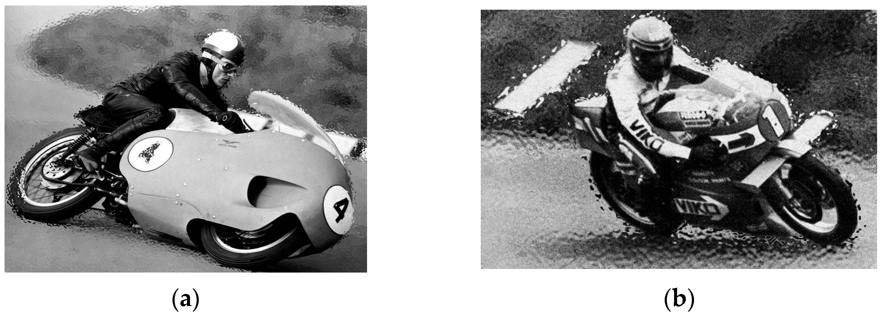
Article

Aerodynamic Study of MotoGP Motorcycle Flow Redirectors

by
Borja González-Arcos
and
Pedro Javier Gamez-Montero
*
Department of Fluid Mechanics, Universitat Politecnica de Catalunya, Campus Terrassa, Colom 11, 08222 Terrassa, Spain
*
Author to whom correspondence should be addressed.
Energies 2023, 16(12), 4793; https://doi.org/10.3390/en16124793
Submission received: 21 May 2023 / Revised: 12 June 2023 / Accepted: 16 June 2023 / Published: 19 June 2023
(This article belongs to the Section J: Thermal Management)

Abstract

:
In recent years, the introduction of aerodynamic appendages and the study of their aerodynamic performance in MotoGP motorcycles has increased exponentially. It was in 2016, with the introduction of the single electronic control unit, that the search began for alternative methods to generate downforce that were not solely reliant on the motorcycle’s electronics. Since then, all types of spoilers, fins and wings have been observed on the fairings of MotoGP motorcycles. The latest breakthrough has been Ducati’s implementation of flow redirectors at the front and bottom of the fairing. The aim of the present study was to test two hypotheses regarding the performance of the flow redirector by responding to the corresponding research questions on its aerodynamic function and advantage, both in the straight and leaning position. In a preanalytical cognitive act, a visual study of MotoGP motorcycles was conducted and, accordingly, a 3D-CAD model was designed ad hoc in compliance with the FIM 2022 regulations for both the motorcycle and flow redirector. Numerical simulations using OpenFOAM software were then carried out for the aerodynamic analysis. Finally, the Taguchi methodology was applied as an effective simulation-based strategy to narrow down the combinations of geometric parameters, reduce the solution space, optimize the number of simulations, and statistically analyse the results. The aerodynamic performance of the flow redirector is highly dependent on the inlet flow when the motorcycle is in a straight position. The results indicate that all models with leaned motorcycle bearing the flow redirector, regardless of geometry, have an aerodynamic advantage, as the appendage generates downforce with a minimal increment of the drag coefficient. In a cornering situation, the flow separator in the flow redirector reduces the disadvantageous influence of wheel rotation on the “diffuser effect” by drawing the flow towards the outside of the curve, creating extra downforce.

1. Introduction

The aerodynamic study of a MotoGP motorcycle is considerably different from that of a self-steering four-wheeled vehicle, such as a Formula 1 car. This is due to the various factors that affect the aerodynamic performance of a racing motorcycle during forward motion, such as changes in angles of attack, gyroscopic ratios, and the movement of the rider.
In recent years, aerodynamics has become a primary area of focus for improving motorcycle performance in the MotoGP World Championship. Following the introduction by the International Motorcycle Federation (FIM) of a simpler electronic control unit (ECU) in 2016, many manufacturers in the MotoGP grid have sought to implement aerodynamic appendages at the front of the motorcycle to prevent wheelie during acceleration, which was previously controlled by electronics [1]. Leading the way in this field has been Ducati, with many other manufacturers following suit or basing their designs on Ducati’s innovations. Among Ducati’s latest aerodynamic add-ons are “flow redirectors”, mounted at the frontal and low area of the fairing, several of which have been replicated by rival manufacturers, including the fins introduced in early 2016 or the spoiler of 2019. However, the type of flow redirector under study here is not an example of this trend. Since its initial implementation by Ducati in 2021, the only other manufacturers on the MotoGP grid observed using a similar appendage have been Honda in the summer of 2022 and KTM at the start of the 2023 season.
The fact that this aerodynamic device is not an inverted wing type makes it difficult to interpret how it affects aerodynamic performance. Thus, doubts arise about whether its purpose is to reduce wheelie under acceleration, or to generate downforce in cornering, or if it bestows some other aerodynamic advantage. The flow redirector is thought to affect the behaviour of the front wheel wake, gaining extra downforce, especially in corners, with a reasonable drag trade-off. Therefore, the purpose of the research presented here was to characterize the aerodynamic performance of this flow redirector on a MotoGP motorcycle.
To meet the research objective, the preanalytical cognitive act that supplies the raw material for the analytic effort was first addressed. It should be noted that there are no available drawings or data regarding the geometry of the Ducati MotoGP motorcycle or the flow redirector. Therefore, the first research question of this study is: “How can a 3D-CAD prototype be designed from scratch without access to any data on the geometry of a real MotoGP motorcycle, including the fairing and aerodynamic appendages?” Another question to be answered is: “How can numerical simulation capture the aerodynamic performance of the flow redirector in a racing situation, such as on a straight or leaning (i.e., cornering) motorbike?” Finally, considering the high computational cost of numerical simulations, and the fact that the CAD design would be carried out with different geometric parameter values, the last research question of this study is: “How can the solution space be reduced through a simple and efficient set of numerical simulations that narrow down the combinations of geometric parameters?”
To develop the study, an ad hoc CAD design of a MotoGP motorbike that complies with the 2022 FIM regulations and features flow redirector-type appendages was created. The study was conducted using computational fluid dynamics (CFD) simulation, and the results were analysed both aerodynamically and statistically. The statistical analysis was carried out using the Taguchi method [2], which is an effective simulation-based strategy for narrowing down the geometric parameter combinations, reducing the solution space, and optimizing the number of simulations. The CFD simulation was performed using OpenFOAM toolbox [3] and the turbulent model used was RANS k-ω SST, a widely accepted suitable model for external aerodynamics [4,5].

2. Background

2.1. Historical MotoGP Aerodynamics

Throughout the history of motorcycle racing, efforts have been made to give motorcycles an aerodynamic advantage. Examples include the fairings introduced by Moto Guzzi or NSU in the 1950s or the spoilers fielded by Rodger Freeth in 1977 [6,7] (see Figure 1).
It was not until 2016, with the introduction of the single electronic control unit, that manufacturers on the MotoGP grid began to explore new aerodynamic solutions. Until then, the major technical evolutions in the MotoGP world, and investment of resources, were in the electronics field, achieving a more efficient torque transfer to the rear wheel and better control of the pitching moment and front wheel lift during acceleration. The single control unit was implemented by Dorna [8], with the aim of equalizing the competition so that the teams with the biggest budgets would not have an advantage when it came to developing electronics.
Subsequently, the manufacturers have focused their attention on the aerodynamic evolution of MotoGP motorcycles led by Ducati, which has set the pace in terms of aerodynamic innovations. The goals, above all, have been to reduce the pitching moment (wheelie) under acceleration and achieve more grip by generating downforce. Firstly, simple fins were attached on the sides of the fairing or in the side area between the dome and the fairing, as Gurney flaps have been used to improve the aerodynamic performance of an airfoil [9]. However, during the 2016 season, the FIM realized that the fins represented a major safety hazard, as they could come in contact with the ground when the motorcycle was leaning steeply or, even worse, they could act as blades, causing serious injuries to the rider [10] (see Figure 2).
Therefore, for safety reasons, the FIM decided to eliminate spoilers or fins from motorcycles in the 2017 season. The new regulations stated that aerodynamic elements must form a closed assembly integrated into the fairing of the motorcycle, resulting in the design of aerodynamic appendages in a wide range of shapes and sizes, as shown in Figure 3.
Finally, in 2019 the FIM placed additional restrictions on the size and shape of the fairings, thus inspiring further inventive engineering from the manufacturers on the grid. The regulations also stipulated that only two different types of fairings and mudguards could be used during a season, and that the aerodynamic elements must not be removable. It was at the opening race of the 2019 season that a flow redirector was first seen (see Figure 4), implemented by Ducati. Located in the lower area of the swingarm, it redirected the flow from the bottom of the motorcycle to the rear wheel. The flow redirector generated controversy among the other MotoGP manufacturers, who cast doubts on its legality. Ducati, in their defence, argued that the function of the three fins forming the appendage was to direct airflow upwards through the space between the underside of the fairing and the rear wheel, thereby helping to reduce the temperature of the rear tyre. The other manufacturers insisted that the new appendage, besides directing airflow to the rear tyre, also generated downforce in the swingarm part of the motorcycle, affording better traction under acceleration. In response, the FIM modified the regulations for 2020 to clarify any grey areas in the MotoGP aerodynamic regulations.
In 2021 a second type of flow redirector, also implemented by Ducati, was first seen on the side of the fairing in the low frontal area. This aerodynamic is the subject of the present study.
More recently, in the 2022 season, other aerodynamic devices have been observed, such as those positioned on the motorcycle’s tail, as shown in Figure 5a. The purpose of this Ducati innovation is allegedly to generate downforce at the back of the motorcycle when leaning in a corner. Additionally, a rear spoiler design from Aprilia was spotted on a test motorcycle (see Figure 5b) but has not been used on factory motorcycles in a race. A new element introduced by KTM in the 2023 MotoGP is the “handle” rear wing (see Figure 5c), which is composed of three fins, the two lateral ones apparently oriented to generate downforce in cornering, while the central one is positioned to generate downforce in a straight line. A design very similar to KTM’s was seen in pre-season testing on the Yamaha but has not been implemented in Yamaha’s motorcycles for the 2023 season.
The 2022 season also witnessed the introduction of a new wider and lower fairing concept, implemented by Aprilia, with the intention of creating ground effect (downforce) when the motorcycle is leaning (see Figure 6). This approach has been followed in the 2023 season by KTM and even Ducati has incorporated it in the motorcycles of the Pramac Racing team.

2.2. Literature Review and Fundamental Theory of Motorcycle Aerodynamics

2.2.1. Literature Review

Motorcycle aerodynamics have been studied from different perspectives. In a commercial approach, Araki and Gotou [12] used scaled motorcycle models in a wind tunnel to redesign the fairing and windshield, achieving reduced drag and aeroacoustic noise and enhanced rider comfort. Likewise, computational fluid dynamics (CFD) were applied by Angeletti et al. [13] to improve the design and comfort of street motorcycles. Additionally, Biancolini et al. [14] utilized the RBF Morph tool, integrated with the ANSYS Fluent CFD solver, to modify mesh geometry (angles of attack, rider position) and aerodynamically optimize the motorcycle windshield design.
A specific field of aerodynamic research is focused on the analysis and performance improvement of sport motorcycles or superbikes. For example, general aerodynamic studies of a racing motorcycle have been carried out by Winski and Piechna [15] and Palanivendhan et al. [16] The work of Winski and Piechna was performed within the MotoStudent university competition, in which students use their analytical skills to conceptualise the motorcycle design and riding experience, as outlined in one study [17]. They focused on a motorcycle in a completely straight position and used several turbulence models, obtaining very accurate results for both the k-ω and S-A model (Spalart–Allmaras) [4,5]. Throughout the study, the pressure distribution, streamlines, and vorticity were analysed, as well as the aerodynamic coefficients. It was concluded that the fairing, front wheel, and suspension are the elements most responsible for creating aerodynamic drag. On the other hand, as the rider plays an important role in the aerodynamics of a motorcycle, Winski and Piechna also studied the effect of the rider in a position of maximum aerodynamic efficiency (“lying” position) and upright (braking position), both adopted by the rider in a race when the motorcycle is completely straight. More specific CFD studies for totally straight geometries have also been carried out, such as the one by Fintelman et al. [18], which examined how crosswinds affect the aerodynamics and stability of the motorcycle. After testing various side wind angles (yaw angles), they concluded that rolling moments, lateral forces, and lift forces increase with the yaw angle, while drag forces decrease.
Other CFD studies have analysed the aerodynamics of sports motorcycles in high-speed corners. For example, Van Dijck [19] studied the aerodynamics of a Kawasaki ZX10-R in SuperStock racing trim at a speed of 38 m/s, with lean angles of 45–55°. Although the lean angle is not constant throughout the curve, Van Dijck calculated that its rate of variation has a negligible effect on aerodynamic forces and pressure distribution (<1.5%). The results show that, in cornering situations where the motorcycle and rider are closer to the ground, the interaction of the high-pressure field from the front of the motorcycle with the ground increases both lift and lateral forces. Moreover, there is a linear increase of lift and drag as the lean angle increases, whereas the variation of the lateral force shows no pattern correlated with different lean angles. Related to this, Concli et al. [20] studied the aerodynamic performance of different designs of racing motorcycle wheels in a leaning position. It was observed that wheels with covered rims or larger discs reduce aerodynamic drag by almost 50%, while also generating more lift.
However, there is a lack of specific literature analysing the performance of aerodynamic appendages on MotoGP motorcycles. One possible reason is the scarcity of CAD models of the latest MotoGP motorcycles, in contrast with Formula 1 vehicles.
González-Arcos used CFD to explore the aerodynamic performance of various appendage configurations based on ad hoc designs of models of different manufacturers in the MotoGP grid of 2020 (Yamaha, Suzuki, and Ducati) [21]. Notably, the geometries used were created by the author based on real MotoGP models and not provided by the manufacturers. The study examined the aerodynamic performance of a MotoGP motorcycle equipped with fin-type appendages that met the FIM 2020 regulations using a completely straight geometry. The results show that the appendages provide front downforce for the motorcycle, above all the Ducati-type device, followed by that of Suzuki. Although generating the least downforce, the Yamaha-type appendage created the least drag, followed by that of Suzuki, with the Ducati design causing the most drag. The aerodynamic effect of such devices during cornering was studied by Sedlak [22] and Segarra i Simó [23]. Sedlak concluded that when the rider hangs off the motorcycle, their leg or elbow reduces the aerodynamic performance of the appendage on the inside of the corner, especially if located close to one of the limbs. Segarra i Simó studied each of the appendages analysed by González-Arcos [21], but with the motorcycle in a leaning position and the rider hanging off to simulate cornering. The results show that the device on the side leaning into the corner generates an unwanted lateral force due to its negative dihedral angle, while the outer appendage does generate downforce. The Ducati-type design generated the most downforce in the corner, but also more lateral force and an opposite moment to the inclination, potentially affecting the motorcycle’s manoeuvrability and stability.
Based on this literature review, it can be concluded that to date no study has analysed the aerodynamic performance of the flow redirector first implemented by Ducati in MotoGP.

2.2.2. Fundamental Theory of Motorcycle Aerodynamics

The main aerodynamic forces generated by a MotoGP motorcycle are drag, lift, and lateral forces. As noted in the introduction, the aerodynamic study of a motorcycle differs from that of a four-wheeled self-steering vehicle [24]. In motorcycles the lift is usually positive at the front axle and negative at the rear axle so, overall, there is practically no lift. This is a consequence of having the centre of pressure in a high position [24]. Drag is the force that opposes forward movement and influences the top speed of the motorcycle, being greatly affected by the rider’s position. When fitting into the dome, the rider ensures maximum aerodynamic efficiency and minimises drag. The rider will then move out of the dome to increase drag in a braking situation. Finally, although lateral force is much less relevant in MotoGP, it can be generated by aerodynamic appendages during cornering, creating stability issues. Lateral force can also increase significantly when there are crosswinds, especially for high sideslip angles, as described by Fintelman et al. [18] and Katz [25]. The acceleration, backing, and moments acting on a racing motorcycle are shown in Figure 7.
  • Acceleration. A motorcycle has only rear-wheel drive, so under acceleration the torque is transferred to the rear wheel, with the motorcycle tending to lift off the front. During this phenomenon, which in the motorcycling world is known as a wheelie, the motorcycle’s electronics reduce the power supply.
  • Braking. Under braking, all the weight of the motorcycle moves forward, which causes the rear wheel to lift off the ground.
  • Pitching moment. The main reason for this moment is that a motorcycle has only two points of contact with the ground, which are aligned on one axle: one behind the other. This fact, combined with the centre of gravity of the motorcycle being positioned higher than that of a four-wheeled vehicle, makes the pitching moment critical, especially during acceleration and braking. Additionally, since both the drag and lift of a motorcycle act on the centre of pressure, which is usually positioned above and in front of the centre of gravity, the combination of the two forces creates a pitching moment around the y-axis [26].
  • Rolling moment. This moment is triggered by the rider when cornering. As MotoGP motorcycles have very little handlebar travel, unlike road motorcycles, many corners cannot be taken with a yaw turn provided by the handlebars. Consequently, when approaching the corner, the rider hangs off the motorcycle, thereby shifting the centre of gravity towards the inside of the corner and providing the necessary lean to take the corner as quickly as possible.
  • Yawing moment. This moment is much less relevant than the previous two, given that handlebar turning is practically non-existent in MotoGP, as mentioned. However, a yaw moment can occur both on corner exit and corner entry when the motorcycle slides off the rear wheel and causes the front and rear wheel to be out of alignment. As a question of safety, it is preferable to have a longitudinal slip of the rear wheel in an acceleration phase, rather than a longitudinal slip of the front wheel in a braking phase [26].
Hence, one objective of aerodynamic design in MotoGP is to increase the downforce of the motorcycle to improve the grip between the tyres and the track. Therefore, during acceleration, the aim is to reduce frontal lift to decrease wheelie possibility and enhance power delivery, while increasing the downforce at the rear to improve tyre grip and traction. Another objective is to minimize drag to achieve a higher top speed and reduce lateral force during cornering to enhance stability.

2.3. Flow Redirector

The flow redirector implemented by Ducati is in a low position at the side of the fairing towards the front (see Figure 8a). This aerodynamic appendage is intended to take the maximum amount of air from the front of the motorcycle and the side of the wheel and redirect it towards the lower part of the motorcycle. The flow redirector thus consists of a large front air inlet located at the height of the front wheel axle, a shroud that radically tapers down to the lowest part of the fairing, and a rear air outlet that is smaller than the inlet (see Figure 8b,d). In addition, in the central part of the flow redirector, a separator divides the appendage to create two different flow paths (see Figure 8c). Finally, the images of Figure 8 show that there is both a horizontal inlet angle (β) and a vertical inlet angle (α) between the appendage and the fairing.

2.3.1. Performance Assumptions

The aerodynamic performance scenarios for this flow redirector are divided into leaning and straight motorcycle modes.

Leaning Mode

When a MotoGP motorcycle goes through a corner it can acquire large lean angles (>60° with respect to the straight vertical position, perpendicular to the ground). This means that a large portion of the fairing comes into close proximity with the ground, generating a phenomenon similar to the ground effect of a Formula 1 car, in which the surface area near the ground acts as a diffuser. As reported by Van Dijck [19], the interaction between the motorcycle and the ground creates a high gradient-pressure zone at the front of and inside the motorcycle, generating a flow pattern towards the low pressure zone on the outside of the curve. In other words, a high-velocity zone of air can be generated that creates downforce without causing any lateral forces, as depicted in Figure 9.
Having established that this phenomenon can be generated, the next step is to examine the role of the flow redirector. This appendage collects air and directs it to the lower part of the fairing so that, when the motorcycle is leaning and the lower part of the fairing is rounded, there is a large flow radius and the lower part of the aerodynamic body acts as a diffusor, as shown in Figure 10.
Thus, the hypothesis to test is: whether the function of the flow redirector during cornering is to accelerate the flow in the lower part of the fairing to create a ground effect and, consequently, to generate downforce.

Straight Motorbike

When the motorcycle is in a completely upright position, it does not appear that the flow redirector alone can provide significant downforce and, in fact, it may even produce lift. However, by redirecting the flow to the lower area of the fairing, it could create a low gradient-pressure zone on the underside of the motorcycle and, therefore, generate downforce. Although the effectiveness of this approach seems unlikely, as the flow can separate when the motorcycle is travelling in a straight line, it provides another hypothesis to test in this work. Accordingly, the flow redirector would have the function of clearing the wake generated by the front wheel, thus reducing the aerodynamic drag force, and making it difficult for other motorcycles to follow the Ducati. This function is schematized in Figure 11.

3. Geometric Design

3.1. Naked Geometric Design

Based on the FIM 2022 regulations for the MotoGP World Championship and a visual study using images of the current MotoGP motorcycles on the grid, a CAD (DS SolidWorks® 28 and FreeCAD® 0.19) design of a MotoGP prototype without aerodynamic appendages was generated. In addition, considering the effect of the rider on motorcycle aerodynamics, the rider position is one of maximum aerodynamic efficiency. The ad hoc 3D model is presented in Figure 12.
The following features from the above design are highlighted:
  • Rim implementation. It was decided that the wheel rims would be implemented because of their potential aerodynamic impact on the flow redirector. It is worth noting that the analysed appendage is located just behind the front wheel, so its performance may be modified by flow structures generated by the rotation of a rimmed wheel. The different manufacturers on the MotoGP grid use different rim geometries, and the present design is based on Honda HRC rims.
  • Fairing narrowing. An important feature of MotoGP design is the narrowing of the fairing, especially in the lower area. The FIM regulations [1] place a limit on motorcycle width, which becomes more restrictive in the lower area. Therefore, to implement the aerodynamic appendage, it is necessary to narrow the fairing at the bottom. The Ducati fairing is visibly the narrowest on the grid, which allows larger devices to be mounted in the lower area of the motorcycle. However, as this also reduces the dimensions of the radiator, it is challenging to narrow the fairing without changing the radiator design, which can cause overheating and reliability issues.
  • Bottom rounding. Finally, the lower part of the fairing is rounded, as this is one of the differences between Ducati motorcycles and those of the other manufacturers. As described in the performance scenarios, the design of the lower part of the fairing can play an important role in the aerodynamic performance of the flow redirector, acting similarly to the diffuser of a Formula 1 single seater when the motorcycle is at an angle.
  • Rider position. As mentioned in the introduction, when a rider is cornering they tilt the motorcycle by hanging off it. This manoeuvre can affect the aerodynamic performance of appendages mounted high on the motorcycle, as demonstrated by Sedlak [22]. However, when located in a low position, the flow redirector is not close enough to the rider’s limbs for its aerodynamic impact to be affected in a cornering situation. As a result, the rider’s position in the model remains unchanged for leaning geometries. Although hanging off the motorcycle likely results in variable drag, as shown by Barbagallo et al. [27], the rider’s cornering position is less relevant in the present study, which is focused exclusively on the performance of the flow redirector.

3.2. Flow Redirector Design

The design was based on a visual study of images and videos of the 2021–2022 Ducati MotoGP motorcycles. The key geometric parameters for the design of the flow redirector are shown in Figure 8. Since there are no reference drawings of the Ducati flow redirector, and the aim was to quantify its aerodynamic performance, the following geometric variables are used:
  • β angle. Among a wide range of potential values, the effect of β = 25° and β = 40° on the aerodynamic performance of the flow redirector was investigated, as shown in Figure 8.
  • α angle. Two vertical angles of attack, α = 0° and α = 10°, were studied, as shown in Figure 8.
  • With/Without flow separator. The functionality and aerodynamic performance provided by the flow separator were also studied.
The other geometric parameters are fixed, as detailed in Table 1 and shown in Figure 13.
Once the MotoGP motorcycle-rider package and the flow redirector were designed, both were assembled. The final geometry complied with the external dimension requirements set by the FIM regulations for the 2022 MotoGP World Championship.

3.3. Adaptation of Geometry to CFD

As shown in the figures, the design has a complex geometry. Given that the present study is focused on aerodynamic performance, certain geometric details were considered irrelevant and potentially negative for the quality of the mesh. Accordingly, a series of changes were implemented, with aim of making the geometry continuous and closed and minimising possible quality errors in the mesh, as shown in Figure 14.
  • The entire engine area is covered to create a closed volume;
  • The rider is joined to the motorcycle to unify the geometry in a single volume;
  • The swingarm was redesigned to cover the engine area and create a closed volume for the CFD analysis.

4. Numerical Methodology

4.1. Mesh Generation

4.1.1. Geometry Preparation

The geometry was imported, placed in the desired position, and a symmetry cut was made for the simulations where the geometry would be in a straight position or tilted at 50° with respect to the ground, as is habitual in simulations with leaning geometry [19]. Additionally, the geometry was cleaned of imperfections, eliminating intersections and excess surfaces. A contact surface was created between the tyres and the ground to avoid the acute angle between the wheels and the ground. This can be a major problem because this angle can lead to the creation of low-quality elements in that area of the mesh, where the boundary layers also meet.

4.1.2. Domain

To ensure a good estimation of the domain, the scheme of Fintelman et al. [18], depicted in Figure 15, was used as a reference, where H is the height of the straight motorcycle-rider geometry, approximated to 1.5 m. Thus, based on the previous scheme, the following distances are applied as shown in Table 2 (straight geometry) and Table 3 (leaning geometry).
It should be noted that only half of the domain was used when simulating the straight motorcycle geometry due to its symmetry with respect to the ZX plane. Conversely, the entire domain was used for simulations of the leaning motorcycle, since in this case symmetry cannot be applied. Within the domain, 4 refinement zones were implemented (see Figure 16):
  • Zone 1. Located in the lower part of the motorcycle, this is the area of maximum refinement as it covers the lower part of the fairing and the wheels, critical for the aerodynamic study.
  • Zone 2. This area covers the entire geometry, leaving certain margins.
  • Zone 3. This area covers Zone 2, leaving margins.
  • Zone 4. This is the outermost zone of the geometry, from Zone 3 to the rear of the volume mesh.
The side view of the mesh presented in Figure 16 clearly shows how the refinement regions created surround the body, concentrating the cells around it, and are intended to provide the best prediction of aerodynamic forces. The smaller refinement region, Zone 1, concentrates the major part of the cells around the geometry, giving special treatment to those critical zones of the body.

4.1.3. Effect of the Boundary Layer

The effect of the boundary layer in the wall was modelled, defining the first cell size in order to obtain a y+ around 50 [28], which involves the use of wall functions as opposed to a near wall treatment, which generally adopts y+ around 1 when solving for a low Reynolds number [29]. From this estimation, the height of the centre of the first cell of the boundary layer was calculated to be 0.41 mm. Thus, the parameters given in Table 4 were applied to model the effect of the boundary layer.
It should be noted that the boundary layer was applied for all surfaces of the geometry (except the internal part of the rims) and the ground (road), as depicted in Figure 16c,d. As the road is a type of moving wall, it was not necessary to have high resolution near the wall. Thus, an aspect ratio of 10% was used for the ground and only 6 layers were applied to remove some elements.

4.1.4. Volume Mesh

Finally, the volume mesh was created and the entire volume of the domain was meshed using the Hexa Interior algorithm, which employs hexahedral elements, with prism and pyramidal elements as transitions between small and larger hexahedral cells. Tetrahedral elements (Tetra Rapid) were used to mesh the internal volume of the inner rim, a small volume of complicated geometry (minimum volume: 1.61 × 10⁻¹¹ m3 and maximum volume: 0.048 m3). This type of algorithm allows a great variation in element length, thus minimising the quality errors in that zone.

4.1.5. Multi-Reference Frame

A multi-reference frame was employed for the tyre volumes, allowing a rotation to be assigned to them without modifying the mesh. As the front and rear wheels have different diameters, these zones also have different angular velocities. The angular velocity is calculated by dividing the velocity of the motorcycle by the tyre radius.

4.1.6. Mesh Quality

The quality of the mesh was checked using the OpenFOAM checkMesh tool and the yPlus function for the values of y+ throughout the geometry [3]. The average values of each part of the geometry were found to be close to 50. Regarding the fairing, an essential element for the study, the value was 47.54. It can therefore be concluded that the quality of the mesh was good. In addition, the GCI methodology [30] was used to study the mesh independence, using 3 meshes of variable refinement, as detailed in Table 5, and analysing the variation of the variable ϕ. In this case the variable ϕ = Cd Sref, where Cd is the drag coefficient and Sref is the frontal area of the geometry (0.550 m2).
The results of the GCI study are given in Table 6.
The GCI values were within the asymptotic range of convergence, with the AR being approximately 1, estimated from r = 1.44 [31]. As the percentage of error between the medium and fine mesh was very small, and fine mesh requires far more computational time, it was assumed that mesh independence could be obtained using the medium mesh (8.8 M elements in symmetrical cases).

4.2. Boundary and Initial Conditions

To assign the boundary conditions, a velocity first has to be chosen for the simulation. Simulations were carried out for both straight and leaning motorcycles and, although this implies two totally different performance situations, a single velocity was estimated for both circumstances.
  • Corner exit. On exiting the corner, the rider straightens the motorcycle as fast as possible and is able to reach velocities of 180–200 km/h [32].
  • Fast corner. Velocities of 150–180 km/h are possible in a fast corner with a leaning angle of more than 50° [32].
Accordingly, a speed of 180 km/h (50 m/s), reachable in both circumstances, was applied for the simulations, and the following boundary conditions were applied:
  • Inlet velocity (free stream velocity): 50 m/s;
  • The road in the simulation is of the movingWall type, with a velocity of 50 m/s;
  • Flow rotation according to the radius of curvature was not simulated for the leaning motorcycle;
  • Symmetry boundary conditions were applied to the side faces of the domain, as well as to the top face and the face of the symmetryPlane when the simulation was symmetrical;
  • The pressure outlet was at atmospheric pressure;
  • Rotation was applied to the tyres and rims by assigning the rotatingWall boundary condition, with a speed of 166.7 rad/s and 144.9 rad/s for the front and rear wheels, respectively. The effect of the aerodynamic interaction of the rotation of a wheel is clearly shown by Cravero and Marsano [33].

4.3. Solver and Turbulent Model

The simulation was carried out using OpenFOAM software [34], applying the simpleFoam solver with incompressible and turbulent flow for steady state aerodynamics. The gradient, divergence, and Laplacian terms of the Navier–Stokes equations were discretised by means of the Gaussian schemes: at cell interfaces, the interpolation schemes were linear (upwind) [35]. The GAMG (Geometric Algebraic Multi Grid) solver was applied for the pressure equation, and the smoothSolver was selected for velocity and turbulence variables. Execution was performed by means of second-order schemes. For the turbulence approach, a RANS type simulation was implemented and the k-ω SST turbulence model was used [33], employing the wall functions listed in Table 7 for each parameter. Wall functions for k, omega, and nut are used. These wall functions are used because of the small cell requirements in certain areas of the mesh where boundary layer is dominant. Hence, a finer application of the values of these parameters would be required to obtain a more accurate solution. [35,36,37].
To simulate the required thermodynamic conditions, it is necessary to estimate the turbulence parameters [38]. The values of the initial conditions of the simulation are shown in Table 8.

4.4. Convergence and Verification of Results

Analysis of the residuals, including force values, revealed that all were below 1 × 10⁻³, verifying that a reasonable convergence of simulation was achieved. When using the steady state simpleFoam solver with a turbulence model, the residuals cannot be any lower due to the unstable nature of the velocity, as one study exemplifies [35]. The conservation of mass between the inlet and outlet was also confirmed, the error between them being 0.002%. Finally, the results were verified by comparing them with the data of another study [21] and the experimental data obtained by Foale [39] for a Honda RS 500, as shown in Figure 17. The values without wheel rotation were compared and the results are presented in Table 9.

5. Taguchi Design

5.1. Details of the Taguchi Methodology

As blueprints of the Ducati MotoGP flow redirectors are unavailable, the design was carried out by examining photographs and videos provided by Dorna [8]. Consequently, to determine the aerodynamic performance of the flow redirector, different values (levels) of certain geometric parameters (factors) were studied. A full factorial study, with an equal number of test data points at each level of each factor, is acceptable if only a few factors are to be investigated, but it is not advisable when there are many factors, or the analysis requires significant computational time [40]. For this reason, the Taguchi method was used, which is a type of design of experiments (DoE). DoE is a statistical technique based on organising and designing a series of experiments in such a way that with the minimum number of tests it is possible to extract useful information to obtain conclusions and optimise the configuration of a process or product [41]. The Taguchi method is a holistic approach to DoE based on the use of orthogonal arrays (OA) to perform factorial experiments that range from small and highly fractionalised to larger full factorial designs [2]. Each OA has a given maximum possible resolution. Selecting an OA depends predominantly on (in order of priority) (i) the number of factors and interactions of interest, (ii) the number of factor levels, and (iii) the desired experimental resolution or cost constraints [42]. This strategy minimises the total number of tests to be performed while still providing meaningful information.
A designer will aim to reduce the time, effort, and costs associated with conducting tests, and numerical simulation can provide advantages in this regard. The application of the Taguchi method in software and computer design has been reported, and Taguchi techniques are demonstrated to be effective simulation-based strategies for narrowing down geometric parameter combinations, reducing solution space, and optimizing the number of simulations [43]. Thus, from the perspective of a designer, the application of the Taguchi method with a numerical simulation technique, such as CFD, helps to reduce the number of test repetitions. The results for the same geometric design parameters, meshing, and simulation conditions remain constant, unlike in a manufacturing process, where a certain amount of variation is inherent in each product due to tolerances. Another important advantage of the Taguchi method is that it is an open tool unrestricted by software and accessible to any end-user. The disadvantage is that the obtained solution is just close to the optimal, does not introduce constraints, and it is difficult to use it to solve multi-objective problems and uncertainty quantification [44,45].

5.2. Procedure

The Taguchi method involves the simultaneous evaluation of two or more factors (parameters) for their ability to affect the mean values or variability of a particular product or process. To achieve this in an effective and statistically sound manner, factor levels are strategically varied, the results of specific test combinations are observed, and the complete set of results is analysed, so that the influential factors and preferred levels can be determined. This analysis helps to identify whether increases or decreases in these levels will potentially lead to further improvements. It should be noted that this is an iterative process, and the initial round in the DoE may lead to subsequent rounds of experimentation.
The main difference between a Taguchi-based DoE and a classical design lies in the way factors are assigned to a specific OA to determine the test combinations. Taguchi designs use OAs to estimate the effects of factors on the response mean and variance. An OA ensures that the design is balanced, in that the factor levels are equally weighted. This allows each factor to be evaluated independently of all other factors, so that the effect of one factor does not affect the estimate of another factor.

5.3. Control and Noise Factors

Taguchi separates the factors into two main groups: control and noise factors.
  • Control factors are set by the designer and cannot be directly modified by the end-user. The control factors were chosen after an audio-visual study of the flow redirectors of a MotoGP motorcycle, and hypotheses were proposed to explain their aerodynamic performance. Therefore, the parameters considered most relevant for the aerodynamic performance of the appendage were selected.
  • The control factors were divided into levels, which offered advantages for each control factor. The levels had to comply with FIM regulations and be adjusted to the reality of the designs, so they were based on audio-visual studies and the riding performance of a Ducati MotoGP motorcycle.
  • Noise factors are not directly controlled by the designer but vary according to the environment and end-user. In this study, wheel rotation was set as a noise factor to observe its effect on the simulation.

5.4. S/N Signal

To analyse the data and determine the optimal levels of the selected factors, the Taguchi method uses the signal-to-noise ratio (S/N) as a performance measure to choose the control levels that best cope with the noise effects. In addition, to fully understand the effects of the factors, it is also necessary to determine the means and standard deviations. A prominent statistical variable is the p-value, which is a probability that measures the evidence against the null hypothesis and concludes whether there is a statistically significant association between the response characteristic and the term.
As the objective was to maximize the aerodynamic performance of the flow redirector, the values of Cd and Cl were minimized (to reduce aerodynamic drag and increase downforce) in response to the signal-to-noise ratio (S/N), which was adjusted to lower-is-better (LB). Therefore, Cd and Cl were the responses to be studied in the Taguchi analysis.

5.5. Taguchi Approach

As mentioned, the Taguchi method is an iterative process. In the first round of the analysis, a few important and influential factors among the many possible factors involved in a process design are determined. The recommended strategy is to start with the smallest orthogonal matrix that can accommodate the largest number of actors, which are simultaneously evaluated at two levels. Therefore, the first step is to assign the control factors and their levels.
Control factors. A total of four control factors:
Levels. Each factor consists of two levels:
  • α: Low level (1) = 0° or high level (2) = 10°;
  • β: Low level (1) = 25° or high level (2) = 40°;
  • Flow separator: Low level (1) = NO or high level (2) = YES;
  • Leaning motorcycle: Low level (1) = NO-perpendicular or high level (2) = YES-50°.
Once these parameters are established, the orthogonal matrix is obtained. All possible combinations of the above factors would be (24) but, by applying an L8 OA (24), only eight trials/meshes were required. It should be noted that wheel rotation did not require a change in mesh quality but simply a modification in the boundary conditions. It was therefore considered a noise factor and applied in all models. The orthogonal arrangement is shown below in Table 10.
As mentioned, the study was focussed on analysing the aerodynamic coefficients Cl and Cd in models with rotating or non-rotating wheels. Additionally, reference simulations were performed in which the motorcycle was without any aerodynamic appendages.

6. Results and Discussion

6.1. Reference Models

To shed light on the aerodynamic advantage provided by a flow redirector, the benchmark simulations depicted in Figure 17 were analysed in comparison with the simulations that include the appendage. The reference simulations were divided into two models:
  • Motorcycle-rider model without aerodynamic appendages in a straight position (perpendicular to the ground);
  • Motorcycle-rider model without aerodynamic appendages in a leaning position (50° to the normal to the ground).

6.1.1. Reference Model with Straight Geometry

The results for the straight geometry are presented in Table 11.

6.1.2. Reference Model with Leaning Geometry

The results for the leaning geometry are presented in Table 12.

6.2. Matrix L8 OA Models

In the assumptions about the aerodynamic performance of the flow redirector, a differentiation was made according to whether the motorcycle is in a leaning or straight position. To simplify the simulation results, the Taguchi models are similarly divided.

6.2.1. Models of a Straight Motorcycle

From this first block of results, models 1::1, 4::1, 6::1, and 7::1 were obtained (Table 10).

Streamlines

The streamlines of each model are presented in Figure 18. The images of Figure 18 illustrate how the appendage collects the flow from the rear of the front wheel and generates vortices that displace the wake of the front wheel, thus fulfilling one of the initial hypotheses of this work (see Section 2.3.1). Regarding the effect of wheel rotation on the streamlines, it can be seen that the flow redirector receives more flow in models with wheel rotation vs. without. For example, in model 1::1, the flow redirector can generate a far more energetic vortex when the wheels are rotating, allowing the wake of the front wheel to move further. Moreover, the wake generated by the front wheel is lifted, creating a high-speed flow near the fairing, and moving the flow so that it has no contact with the rear wheel. With non-rotating wheels, the flow around the flow redirector increases (not going through its interior) and generates a vortex at the exit of the appendage, as can be seen in model 6::1, for example.
Regarding the effect of the flow separator (see Figure 8c), the images of Figure 18 show that in the models with the separator, the flow inside the appendage decreases and, therefore, the generated vortex is also less energetic. Finally, it should be noted that for models 6::1 and 7::1, the flow entering the appendage is also reduced, which may be due to the vertical angle of entry (α = 10°).

Cp of the Lower Fairing

The Cp of the underside of the fairing in each model is illustrated in Figure 19.
In all the models in Figure 19, it can be seen that the Cp is reduced in the fairing area downstream of the flow redirector (X = 0.85 m to X = 1 m). However, models 6::1 and 4::1 have the lowest pressure peak as both include the flow separator, which accelerates the flow leaving the appendage, thus creating a reduced pressure zone in the lower part of the fairing.
Another phenomenon shown in the previous graphs is that above X = 1 m, models 4::1 and 7::1 cannot maintain the low-pressure zone in the lower part of the fairing. The explanation can be seen in Figure 18, which shows that these two models generate the least energetic vortex and therefore cannot maintain the low-pressure zone throughout the fairing, resulting in a separation of flow.

Aerodynamic Coefficients of Straight Models

The aerodynamic coefficients of models implemented in the L8 OA matrix and the differences between the reference model and the straight motorcycle are presented in Table 13.
Based on the above results, model 1::1 with rotating wheels stands out, as it achieves a minimal reduction of both the lift and drag coefficients. Notably, this is the model that generates the most energetic vortex and manages to maintain a low Cp along the entire lower part of the fairing. Therefore, the initial hypothesis that the flow redirector can reduce the aerodynamic drag by clearing the wake of the front wheel is fulfilled. It should also be noted that models 1::1 and 6::1 without rotating wheels achieve a higher percentage of reduction in the lift coefficient (creating more downforce). This is consistent with the results observed in Figure 19, where these two models maintain the Cp below the reference values throughout the lower fairing. Finally, the large difference in results obtained for the same model with and without wheel rotation suggests that the tested aerodynamic appendage is very sensitive to inlet flow, at least in a motorcycle in a straight position (it should be pointed out that the model without wheel rotation is merely a simulation tool and does not reflect a real-life situation).

6.2.2. Models of Leaning Motorcycles

The models with leaning geometry are 2::1, 3::1, 5::1, and 8::1 (see Table 10).

Streamlines

The streamlines of the individual models are presented in Figure 20, Figure 21, Figure 22 and Figure 23.
The images of motorcycles with a leaning geometry reveal that, in all cases, part of the flow entering the appendage closest to the ground exits through the lower part of the fairing towards the outside of the curve. This observation verifies the initial hypothesis (Section 2.3.1) that the appendage generates a diffuser effect by drawing the flow to the outer curve when the motorcycle is cornering. It can be seen that the flow separator accelerates the flow inside the appendage, which facilitates the diffuser effect, particularly affecting the flow passing through the lower part of the appendage.
Finally, in models with wheel rotation, the diffuser effect of the flow redirector is lower, as less flow is drawn to the outside of the curve. The reduction of the diffuser effect is observed, above all, in the models without a flow separator (models 3::1 and 5::1).

Aerodynamic Coefficients in Leaning Models

The aerodynamic coefficients of each leaning model with an appendage and the differences with respect to the reference model are shown in Table 14.
Analysing the above results, the lift coefficient is clearly reduced in all models with a flow redirector irrespective of their geometric characteristics, indicating that this appendage provides an aerodynamic advantage by generating downforce. Among the models without wheel rotation, models 3::1 and 5::1 (without a flow separator) have a considerable aerodynamic advantage, the lift coefficient being reduced by more than 100%. With wheel rotation, the reduction in the lift coefficient is very similar for each model (around 65–84%). This is consistent with the results reported in the previous section, which show that wheel rotation has a greater impact on the diffuser effect of models without a flow separator. Additionally, the flow separator reduces the appendage flow, so that in general very similar performances are obtained for all the models with wheel rotation.
On the other hand, the drag coefficient increased in all models, but only to a small extent (maximum increase of less than 5%), a result that can be expected after the addition of the appendage. However, in the leaning position, the increase in the drag coefficient is less relevant as the main goal is a lower lift coefficient. The results of model 5::1 are striking, as it provides the greatest reduction in the lift coefficient with both rotating and non-rotating wheels.

6.3. Taguchi Method Results

In this section, the results obtained in the Taguchi analysis are presented. The Minitab® 19 software package (State College, PA, USA) was used for additional data processing. In all experiments, the significance level was set as 0.05, and means and standard deviations were calculated for all control factors. A p-value below 0.05 indicates a statistically significant association between the response characteristic and the term. A p-value between the significance levels of 0.05 and 0.1 was used to evaluate terms and was considered to have practical significance. A higher p-value indicates that no statistically significant differences were observed.
In this study, only the leaning motorcycle had p-values lower than alpha, being 0.027 for Cl and 0.015 for Cd. Therefore, only the leaning motorcycle had a statistically significant association with the aerodynamic performance coefficients Cl or Cd. Additionally, the interaction between both angles of the flow redirector (α and β) was tested, but the results were not statistically significant.

Main Effects on S/N Ratios

Main effect plots show how each factor affects the response characteristic (S/N ratio, means, slopes, standard deviations), providing a graphic visualization of the importance of the chosen control parameters. The larger the vertical increment between the two levels and the higher the slope in each factor, the more influential the parameter [43]. In the present study, as the values of Cl and Cd needed to be as low as possible, the criterion of lower-is-better (LB) was used. The main effects determined for the Cl are presented in Figure 24.
The above graph shows that the factor with the greatest effect on the S/N ratio was the leaning position of the motorcycle. Furthermore, analysing the levels of each control factor and obtaining the levels for which the S/N ratio is highest revealed the best combination for the Cl, as shown in Table 15.
As can be seen, the best Cl result was obtained when the motorbike was leaning, which is consistent with the aerodynamic results. All the combinations resulting in an optimum Cl coincide with model 5::1, which also stands out in the aerodynamic analysis. The results of the main effects on the Cd are depicted in Figure 25. The ideal combination of the control factor levels for the Cd was extracted from the above graph and is presented in Table 16.
Analysis of these levels reveals that they coincide with model 1::1, which is the only model found to be capable of reducing the drag coefficient in the aerodynamics analysis.
Finally, an analysis of all the results shows that the flow redirector is designed mainly to provide an aerodynamic advantage in cornering by increasing the downforce of the motorcycle. With the motorcycle in a completely straight position, one model (1::1) provided an aerodynamic advantage with a slight reduction in drag and lift coefficients. However, the aerodynamic performance of a straight motorcycle can be improved mainly by the downforce, generated by wing-like appendages mounted in the highest part of the fairing.

7. Conclusions

The research objective of this study, which was to characterize the aerodynamic performance of flow redirectors in a MotoGP motorcycle, has been fulfilled. The appendages deployed by Ducati, the first manufacturer on the MotoGP grid to implement flow redirectors, are of larger dimensions than those used by their rivals. The Ducati motorcycle has several features that allow these flow redirectors to be mounted without breaking any FIM regulations or causing reliability issues, such as a narrow fairing, reduced air intake to the radiator, and a rounded lower fairing.
In confirmation of an initial hypothesis, the ad hoc CAD models generated in this study indicate that being able to create a vortex in the lower part of the straight motorcycle is of great importance, as it displaces the wake of the front wheel. However, the anticipated advantages for aerodynamic performance in terms of drag and lift reduction were only observed in one model. The models with straight geometry showed that wheel rotation also has a significant aerodynamic effect, especially in the creation of downforce. Therefore, the aerodynamic performance of the flow redirector is highly sensitive to the type of inlet flow when the geometry is in a straight position.
The leaning models reveal that the flow redirector provides an aerodynamic advantage in terms of added downforce compared to the reference model, resulting in a reduction in the Cl. This verifies the hypothesis that the main function of the appendages is to create downforce while cornering. In contrast with the straight models, wheel rotation has a more predictable effect on aerodynamic performance when the motorcycle is at an angle, particularly in downforce generation, since in all cases it reduced the aerodynamic advantages of the appendage somewhat. The explanation lies in that the flow affecting the appendage on the side leaning into the corner is less disturbed, resulting in fewer significant changes in performance. The aerodynamic analysis is supported by the statistical results of the Taguchi method, which identify the most significant control factor and the associated geometry. Moreover, the models that stand out in the aerodynamic investigation coincide with the optimum combinations obtained in the statistical analysis.
Finally, it should be noted that this is a first approximation to a Taguchi-based design of experiments for the aerodynamic analysis of the flow redirector, and therefore the results are preliminary. In future work, it is proposed that the range of the matrix be increased (more simulations) as well as the number of levels (to three) for the factors of the flow separator and leaning position, as these were found to be the most influential. In addition, parameters from the turbulence model and set-up of the simulation can be introduced as noise factors in OpenFOAM® 7.

Author Contributions

Conceptualization, B.G.-A. and P.J.G.-M.; methodology, B.G.-A. and P.J.G.-M.; software, B.G.-A.; validation, B.G.-A. and P.J.G.-M.; writing—original draft preparation, B.G.-A.; writing—review and editing, B.G.-A. and P.J.G.-M.; supervision, P.J.G.-M.; project administration, P.J.G.-M. All authors have read and agreed to the published version of the manuscript.

Funding

This research received no external funding.

Data Availability Statement

Not applicable.

Acknowledgments

The authors would like to acknowledge the Generalitat de Catalunya for providing the necessary support to the research groups IAFARG (SGR 286, https://iafarg.upc.edu, accessed on 1 April 2023), CATMech (Tecnio, https://catmech.upc.edu/home, accessed on 1 April 2023).

Conflicts of Interest

The authors declare no conflict of interest.

References

  1. 2022 FIM GP World Championship Regulations. Available online: http://www.fim-live.com/en/library/ (accessed on 1 March 2022).
  2. Taguchi, G. Introduction to Quality Engineering: Designing Quality into Products and Processes; Asian Productivity Organization: Tokyo, Japan, 1986. [Google Scholar]
  3. OpenFOAM Foundation. OpenFOAM Resources|Documentation|OpenFOAM. Available online: https://openfoam.org/resources/ (accessed on 1 May 2022).
  4. Wilcox, D.C. Turbulence Modeling for CFD, 3rd ed.; DCW Industries, Inc.: New Delhi, India, 2006. [Google Scholar]
  5. Menter, F.R.; Kuntz, M.; Langtry, R. Ten years of industrial experience with the SST turbulence model. Turbul. Heat Mass Transf. 2003, 4, 625–632. [Google Scholar]
  6. De Garnica Cortezo, S. La Compleja Historia de la Inolvidable Moto-Guzzi con Motor de 8 Cilindros. Available online: https://www.abc.es/motor/motos/abci-compleja-historia-inolvidable-moto-guzzi-motor-8-cilindros-202112172355_noticia.html (accessed on 1 April 2023).
  7. Motospot. The Flying Doctor, Rodger Freeth, the Visionary with Wings! Available online: https://en.motospot-oldnews.com/single-post/the-flying-doctor-rodger-freeth-the-visionary-with-wings (accessed on 1 April 2023).
  8. Dorna. Available online: https://www.dorna.com/ (accessed on 1 March 2022).
  9. Fernandez-Gamiz, U.; Gomez-Mármol, M.; Chacón-Rebollo, T. Computational modeling of gurney flaps and microtabs by POD method. Energies 2018, 11, 2091. [Google Scholar] [CrossRef] [Green Version]
  10. Pérez De Rozas, E. Iannone Golpeó a Márquez con el Alerón de su Ducati. Available online: https://www.elperiodico.com/es/motogp/20160405/iannone-marquez-golpe-aleron-ducati-gp-argentina-5029520 (accessed on 1 April 2022).
  11. González, N. el Año que MotoGP Reinventó el Carenado. 2017. Available online: https://www.motociclismo.es/mundial-motogp/articulo/2017-ano-motogp-reinvento-carenado (accessed on 1 April 2022).
  12. Araki, Y.; Gotou, K. Development of Aerodynamic Characteristics for Motorcycles Using Scale Model wind Tunnel; SAE Technical Paper; SAE: Chicago, IL, USA, 2001. [Google Scholar]
  13. Angeletti, M.; Sclafani, L.; Bella, G.; Ubertini, S. The role of CFD on the aerodynamic investigation of motorcycles. SAE Trans. 2003, 112, 1103–1111. [Google Scholar]
  14. Biancolini, M.E.; Biancolini, C.; Costa, E.; Gattamelata, D.; Valentini, P.P. Industrial application of the meshless mopher rbf morph to a motorbike windshield optimisation. In Proceedings of the European Automotive Simulation Conference (EASC), München, Germany, 30 March 2009; pp. 6–7. [Google Scholar]
  15. Winski, K.; Piechna, A. Comprehensive CFD aerodynamic simulation of a sport motorcycle. Energies 2022, 15, 5920. [Google Scholar] [CrossRef]
  16. Palanivendhan, M.; Nagpal, D.; Rao, D.A.; Philip, J.; Ganapathi, M.S. Design and analysis of an aerodynamic kit for a two wheeled race motorcycle. Mater. Today Proc. 2021, 45, 7239–7246. [Google Scholar] [CrossRef]
  17. Gadola, M.; Chindamo, D. Experiential learning in engineering education: The role of student design competitions and a case study. Int. J. Mech. Eng. Educ. 2019, 47, 3–22. [Google Scholar] [CrossRef]
  18. Fintelman, D.; Hemida, H.; Sterling, M.; Li, F.-X. A numerical investigation of the flow around a motorbike when subjected to crosswinds. Eng. Appl. Comput. Fluid Mech. 2015, 9, 528–542. [Google Scholar] [CrossRef] [Green Version]
  19. Van Dijck, T. Computational Evaluation of Aerodynamic Forces on a Racing Motorcycle during High Speed Cornering; SAE Technical Paper; SAE: Chicago, IL, USA, 2015. [Google Scholar]
  20. Concli, F.; Gobbi, M.; Gorla, C. Comparative study of the aerodynamic performances of motorcycle racing wheels using numerical CFD simulations. Adv. Fluid Mech. XII 2018, 120, 185. [Google Scholar]
  21. González-Arcos, B. Estudio del Diseño y Análisis de los Apéndices Aerodinámicos en MotoGP. Bachelor’s Thesis, Universitat Politecnica de Catalunya, Barcelona, Spain, 2020. [Google Scholar]
  22. Sedlak, V. Motorcycle Cornering Improvement: An Aerodynamical Approach based on Flow Interference. Master’s Thesis, KTH Royal Institute of Technology, Stockholm, Sweden, 2012. [Google Scholar]
  23. Segarra i Simó, P. Estudio Aerodinámico del Paso por Curva en MotoGP. Bachelor’s Thesis, Universitat Politecnica de Catalunya, Barcelona, Spain, 2022. [Google Scholar]
  24. Katz, J. Aerodynamics in motorsports. Proc. Inst. Mech. Eng. Part P J. Sport. Eng. Technol. 2021, 235, 324–338. [Google Scholar] [CrossRef]
  25. Katz, J. Aerodynamic drag and downforce of a competition motorcycle. SAE Int. J. Adv. Curr. Pract. Mobil. 2022, 4, 1989–1998. [Google Scholar]
  26. Cossalter, V.; Lot, R.; Massaro, M. Motorcycle dynamics. In Modelling, Simulation and Control Two-Wheel Vehicles; John Wiley & Sons: Hoboken, NJ, USA, 2014; pp. 1–42. [Google Scholar]
  27. Barbagallo, R.; Sequenzia, G.; Oliveri, S.; Cammarata, A. Dynamics of a high- performance motorcycle by an advanced multibody/control co-simulation. Proc. Inst. Mech. Eng. Part K J. Multi-Body Dyn. 2016, 230, 207–221. [Google Scholar] [CrossRef]
  28. Salim, S.M.; Cheah, S. Wall y strategy for dealing with wall-bounded turbulent flows. Proc. Int. Multiconf. Eng. Comput. Sci. 2009, 2, 2165–2170. [Google Scholar]
  29. Moukalled, F.; Mangani, L.; Darwish, M. The Finite Volume Method in Computational Fluid Dynamics; Springer: Berlin/Heidelberg, Germany, 2016; Volume 6, p. 236. [Google Scholar]
  30. Celik, I.B.; Ghia, U.; Roache, P.J.; Freitas, C.J. Procedure for estimation and reporting of uncertainty due to discretization in CFD applications. J. Fluids Eng.-Trans. ASME 2008, 130, 078001. [Google Scholar] [CrossRef] [Green Version]
  31. Roache, P.J. Perspective: A Method for Uniform Reporting of Grid Refinement Studies. ASME J. Fluids Eng. 1994, 116, 405–413. [Google Scholar] [CrossRef]
  32. Tissot Pole Lap 2022 Catalan. Available online: https://www.youtube.com/watch?v=EUZEvVe5QMs (accessed on 1 May 2022).
  33. Cravero, C.; Marsano, D. Computational Investigation of the Aerodynamics of a Wheel Installed on a Race Car with a Multi-Element Front Wing. Fluids 2022, 7, 182. [Google Scholar] [CrossRef]
  34. Maric, T.; Höpken, J.; Mooney, K.G. The OpenFOAM® Technology Primer; Sourceflux: Duisburg, Germany, 2014. [Google Scholar]
  35. Guerrero, A.; Castilla, R. Aerodynamic study of the wake effects on a formula 1 car. Energies 2020, 13, 5183. [Google Scholar] [CrossRef]
  36. Blazek, J. Computational Fluid Dynamics: Principles and Applications; Butterworth-Heinemann: Waltham, MA, USA, 2015. [Google Scholar]
  37. Porcar, L.; Toet, W.; Gamez-Montero, P.J. Study of the effect of vertical airfoil endplates on diffusers in vehicle aerodynamics. Designs 2021, 5, 45. [Google Scholar] [CrossRef]
  38. Greenshields, C.J.; Weller, H.G. Note on Computational Fluid Dynamics: General Principles; CFD Direct: Boston, MA, USA, 2022. [Google Scholar]
  39. Foale, T. Motorcycle Handling and Chassis Design: The Art and Science; Tony Foale: 2022. Available online: https://motochassis.com/product/book-motorcycle-handling-chassis-design/ (accessed on 1 April 2023).
  40. Unal, R.; Dean, E.B. Taguchi approach to design optimization for quality and cost: An overview. In Proceedings of the 1991 Annual Conference of the International Society of Parametric Analysts, Edinburgh, UK, 11–16 August 1991. [Google Scholar]
  41. Phadke, M.S. Quality Engineering Using Robust Design; Prentice Hall International: Englewood Cliffs, NJ, USA, 1989. [Google Scholar]
  42. Ross, R. Taguchi Techniques for Quality Engineering, 2nd ed.; McGraw-Hill: New York, NY, USA, 1996. [Google Scholar]
  43. Gamez-Montero, P.J.; Bernat-Maso, E. Taguchi techniques as an effective simulation-based strategy in the design of numerical simulations to assess contact stress in gerotor pumps. Energies 2022, 15, 7138. [Google Scholar] [CrossRef]
  44. Cravero, C.; De Domenico, D.; Marsano, D. The use of uncertainty quantification and numerical optimization to support the design and operation management of air-staging gas recirculation strategies in glass furnaces. Fluids 2023, 8, 76. [Google Scholar] [CrossRef]
  45. Xia, L.; Zou, Z.J.; Wang, Z.H.; Zou, L.; Gao, H. Surrogate model based uncertainty quantification of CFD simulations of the viscous flow around a ship advancing in shallow water. Ocean Eng. 2021, 234, 109206. [Google Scholar] [CrossRef]
Figure 1. Examples of aerodynamic innovations in World Championship motorcycle fairings: (a) Giulio Cesare Carcano riding the Moto Guzzi; (b) Rodger Freeth on the Yamaha TZ750 with spoilers in 1977.
Energies 16 04793 g001
Figure 2. Image from Márquez’s rear on-board camera at the moment of impact.
Energies 16 04793 g002
Figure 3. Comparison of the different MotoGP fairings in 2017. Source: (González, n.d. [11]).
Energies 16 04793 g003
Figure 4. Michele Pirro, Ducati test rider for Qatar GP 2019.
Energies 16 04793 g004
Figure 5. Examples of rear aerodynamic elements in MotoGP: (a) rear wings introduced by Ducati for the 2022 MotoGP season; (b) rear wings introduced by Aprilia on the test motorbike for the 2022 MotoGP season; (c) rear wings introduced by KTM for the 2023 MotoGP season.
Energies 16 04793 g005
Figure 6. Wider and lower fairing concept introduced by Aprilia in the 2022 MotoGP season.
Energies 16 04793 g006
Figure 7. Motorcycle-rider geometry with axes, aerodynamic forces, and moments: (a) front view of the motorcycle-rider geometry showing aerodynamic lateral force and the axes positioned at the origin; (b) side view of the motorcycle-rider geometry showing the aerodynamic forces (lift and drag), the moments, and the axes positioned at the origin.
Energies 16 04793 g007
Figure 8. Variables of the Ducati flow redirector (values given in Table 1): (a) Ducati front view with flow redirector reference variables: horizontal inlet angle (β) and lateral inlet angle (φ); (b) Ducati side view with flow redirector reference variables: vertical inlet angle (α) and total length (L); (c) appendage entry with reference variables: total inlet height (Hf) and lower inlet width (Af); (d) appendage outlet with reference variables: total outlet height (Ht) and lower outlet width (At).
Energies 16 04793 g008
Figure 9. Ground effect when the motorcycle is leaning.
Energies 16 04793 g009
Figure 10. Lower part of the fairing acting as a diffuser when the motorcycle is leaning.
Energies 16 04793 g010
Figure 11. Flow directed by the appendage clearing the wake of the front wheel on a straight motorcycle.
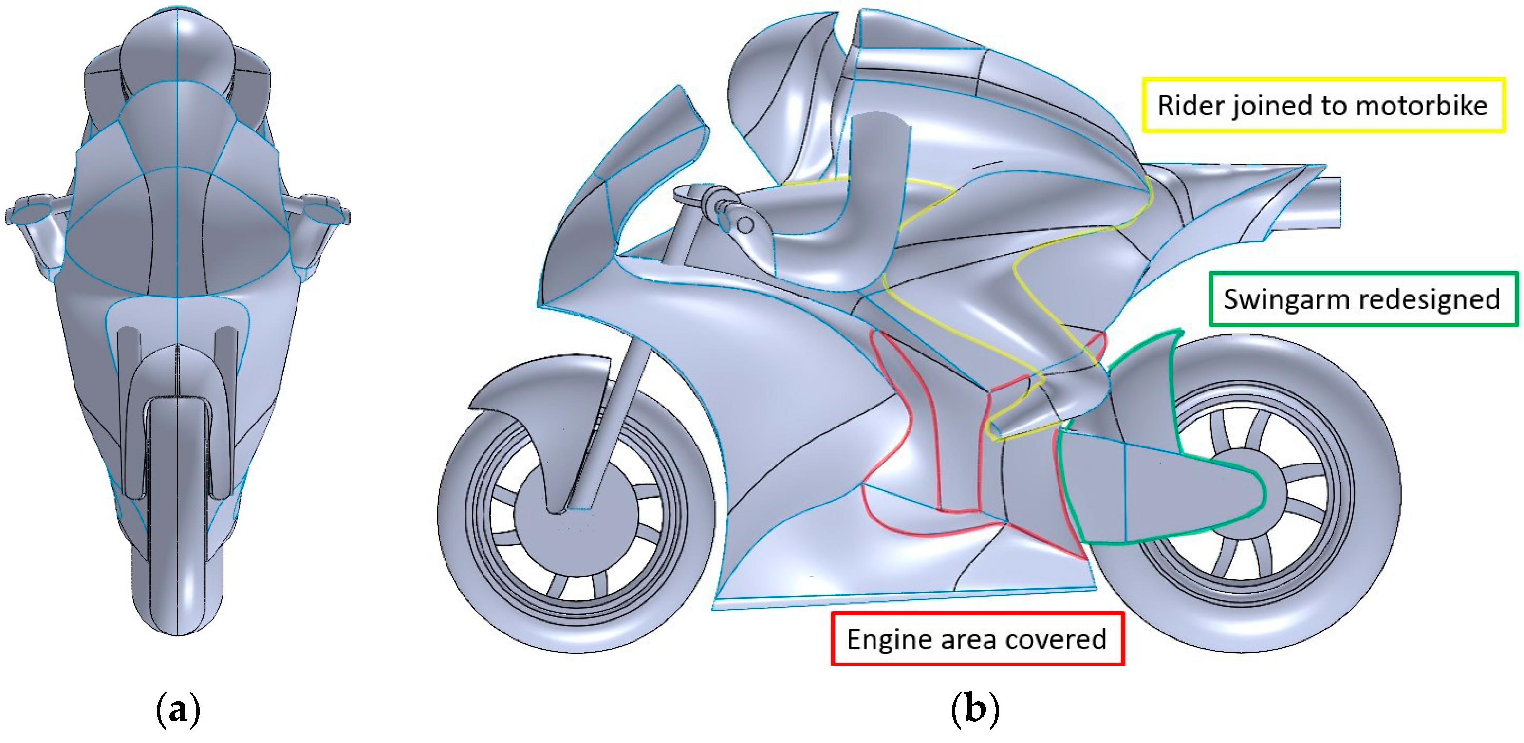
Energies 16 04793 g011
Figure 12. Motorcycle-rider geometry: (a) front view of the motorcycle-rider geometry; (b) side view of the motorcycle-rider geometry.
Energies 16 04793 g012
Figure 13. Fixed dimensions of the flow redirector geometry.
Energies 16 04793 g013
Figure 14. Motorcycle-rider geometry adapted for CFD simulations: (a) front view; (b) side view.
Energies 16 04793 g014
Figure 15. Simulation domain as a function of H.
Energies 16 04793 g015
Figure 16. Refinement zones and mesh layers: (a) isometric image of the domain with refinement zones; (b) isometric image of the geometry with refinement zones; (c) mesh layers: tyre bottom, contact patch, and road; (d) mesh layers: fairing, front wheel cover, and tyre.
Energies 16 04793 g016
Figure 17. Comparison of reference motorcycles to verify the results: (a) Freddie Spencer’s 1984 Honda NS500; (b) reference model without rims designed by González-Arcos [21]; (c) reference model designed for the present study.
Energies 16 04793 g017
Figure 18. Streamlines of models with straight geometry: (a) side view of streamlines with velocity magnitude (m/s) in model 1::1 without wheel rotation; (b) side view of streamlines with velocity magnitude (m/s) in model 1::1 with rotating wheels; (c) side view of streamlines with velocity magnitude (m/s) in model 4::1 without wheel rotation; (d) side view of streamlines with velocity magnitude (m/s) in model 4::1 with rotating wheels; (e) side view of streamlines with velocity magnitude (m/s) of model 6::1 without wheel rotation; (f) side view of streamlines with velocity magnitude (m/s) of model 6::1 with rotating wheels; (g) side view of streamlines with velocity magnitude (m/s) in model 7::1 without wheel rotation; (h) side view of streamlines with velocity magnitude (m/s) in model 7::1 with rotating wheels.
Energies 16 04793 g018
Figure 19. Cp of the lower fairing in models with a straight geometry: (a) Cp of the lower fairing in model 1::1; (b) Cp of the lower fairing in model 4::1; (c) Cp of the lower fairing in model 6::1; (d) Cp of the lower fairing in model 7::1.
Energies 16 04793 g019
Figure 20. Streamlines with magnitude of velocity (m/s) around the flow redirector in model 2::1: (a) bottom view of streamlines with velocity magnitude (m/s) in model 2::1 without wheel rotation; (b) bottom view of streamlines with velocity magnitude (m/s) in model 2::1 with rotating wheels; (c) rear view of the flow redirector and the streamlines with velocity magnitude (m/s) in model 2::1 without wheel rotation; (d) rear view of the flow redirector and the streamlines with velocity magnitude (m/s) in model 2::1 with rotating wheels.
Energies 16 04793 g020
Figure 21. Streamlines with magnitude of velocity (m/s) around the flow redirector in model 3::1: (a) bottom view of streamlines with velocity magnitude (m/s) in model 3::1 without wheel rotation; (b) bottom view of streamlines with velocity magnitude (m/s) in model 3::1 with rotating wheels; (c) rear view of the flow redirector and the streamlines with velocity magnitude (m/s) in model 3::1 without wheel rotation; (d) rear view of the flow redirector and the streamlines with velocity magnitude (m/s) in model 3::1 with rotating wheels.
Energies 16 04793 g021
Figure 22. Streamlines with magnitude of velocity (m/s) around the flow redirector in model 5::1: (a) bottom view of streamlines with velocity magnitude (m/s) in model 5::1 without wheel rotation; (b) bottom view of streamlines with velocity magnitude (m/s) in model 5::1 with rotating wheels; (c) rear view of the flow redirector and the streamlines with velocity magnitude (m/s) in model 5::1 without wheel rotation; (d) rear view of the flow redirector and the streamlines with velocity magnitude (m/s) in model 5::1 with rotating wheels.
Energies 16 04793 g022
Figure 23. Streamlines with magnitude of velocity (m/s) around the flow redirector in model 8::1: (a) bottom view of streamlines with velocity magnitude (m/s) in model 8::1 without wheel rotation; (b) bottom view of streamlines with velocity magnitude (m/s) in model 8::1 with rotating wheels; (c) rear view of the flow redirector and the streamlines with velocity magnitude (m/s) in model 8::1 without wheel rotation; (d) rear view of the flow redirector and the streamlines with velocity magnitude (m/s) in model 8::1 with rotating wheels.
Energies 16 04793 g023
Figure 24. Main effects plot for the Cl.
Energies 16 04793 g024
Figure 25. Main effects plot for the Cd.
Energies 16 04793 g025
Table 1. Fixed variables set for the flow redirector design (see Figure 8).
Geometric VariablesFixed Value
φ35°
L200 mm
Hf170 mm
Af65 mm
Ht110 mm
At40 mm
Table 2. Domain dimensions with respect to the straight geometry for each of the space directions (see Figure 15).
Domain VariablesValue
X+15 m
Y+0 m
Z+9 m
X−6 m
Y−4.5 m
Z−0
Table 3. Domain dimensions with respect to the leaning geometry for each of the space directions (see Figure 15).
Domain VariablesValue
X+15 m
Y+4.5 m
Z+9 m
X−6 m
Y−4.5 m
Z−0
Table 4. Main parameters for the model of the effect of the boundary layer.
ParametersValue
y+50
y0.41 mm
Height of the First Layer0.8 mm
Type Value First HeightAbsolute
Growth Rate1.15
Number of Layers9
Table 5. Characteristics of the meshes in the GCI study.
Mesh TypeCellsCd
Coarse (3)6,326,7060.4488
Medium (2)8,861,2270.4334
Fine (1)13,037,1250.4332
Table 6. GCI study results.
VariablesResults
r231.4006
r121.4713
ϕ30.2468
ϕ20.2384
ϕ10.2383
P12.0057
GCI230.0564%
GCI120.0008%
Table 7. Wall functions used by the OpenFOAM k-ω SST model.
ParameterOpenFOAM Wall Function
kkqRWallFunction
omegaomegaWallFunction
nutnutWallFunction
Table 8. Simulation turbulence parameters.
ParameterValue
Free Stream Velocity (U)50 m/s
Turbulent Intensity (I)1%
Reference Length (l)0.7 m
Kinematic Viscosity (ν)1.5 × 10⁻⁵ m2/s
Turbulence Kinetic Energy (k)0.375 m2/s2
Turbulence Model Constant (Cµ)0.09
Specific Turbulent Dissipation Rate (ω)1.597 s−1
Table 9. Results verification.
Comparative DataHonda RS 500(González-Arcos, 2020) ModelDesigned Model
S Cd0.2400.2340.231
Table 10. Matrix L8 OA used for the study.
1st Modification2nd Modification3rd Modification4th Modification
L8 OA Internal Matrix (Control Factors)1234
Control FactorABDG
Test No. (Row)/Factor No. (Column)α [°]β [°]Flow Separator [-]Leaning Motorcycle [-]
1::1025NONO
2::1025YESYES
3::1040NOYES
4::1040YESNO
5::11025NOYES
6::11025YESNO
7::11040NONO
8::11040YESYES
Table 11. Aerodynamic coefficients for the reference model with a straight motorcycle.
Aerodynamic
Coefficients
Without Rotating WheelsRotating WheelsDifference (%)
Cd0.420330.41131−2.15
Cl0.041970.0507620.94
Table 12. Aerodynamic coefficients for the reference model with a leaning motorcycle.
Aerodynamic
Coefficients
Without Rotating WheelsRotating WheelsDifference (%)
Cd0.462090.44717−3.23
Cl0.087660.1200936.00
Table 13. Difference in % between each straight model and the reference model. The objective was to reduce the two aerodynamic coefficients, aiming for a negative percentage.
ModelSimulation TypeAerodynamic CoefficientValueDifference from Reference (%)
1::1Without Rotating WheelsCd0.437514.09
1::1Without Rotating WheelsCl0.03713−11.53
1::1Rotating WheelsCd0.40788−0.83
1::1Rotating WheelsCl0.05044−0.63
4::1Without Rotating WheelsCd0.438134.23
4::1Without Rotating WheelsCl0.0484515.43
4::1Rotating WheelsCd0.426703.74
4::1Rotating WheelsCl0.0683534.65
6::1Without Rotating WheelsCd0.446096.13
6::1Without Rotating WheelsCl0.03408−18.80
6::1Rotating WheelsCd0.420592.26
6::1Rotating WheelsCl0.055729.77
7::1Without Rotating WheelsCd0.446176.15
7::1Without Rotating WheelsCl0.0548430.66
7::1Rotating WheelsCd0.418631.78
7::1Rotating WheelsCl0.055729.77
Table 14. Difference in % of each of the leaning models with respect to the reference model. Downforce gain is Cl reduction.
ModelSimulation TypeAerodynamic CoefficientValueDifference from Reference (%)
2::1Without Rotating WheelsCd0.476373.09
2::1Without Rotating WheelsCl0.02382−72.83
2::1Rotating WheelsCd0.466194.25
2::1Rotating WheelsCl0.04213−64.92
3::1Without Rotating WheelsCd0.462620.11
3::1Without Rotating WheelsCl−0.00188−102.14
3::1Rotating WheelsCd0.460963.08
3::1Rotating WheelsCl0.03024−74.82
5::1Without Rotating WheelsCd0.462160.02
5::1Without Rotating WheelsCl−0.00714−108.15
5::1Rotating WheelsCd0.457442.27
5::1Rotating WheelsCl0.01942−83.83
8::1Without Rotating WheelsCd0.473932.56
8::1Without Rotating WheelsCl0.01901−78.31
8::1Rotating WheelsCd0.454791.70
8::1Rotating WheelsCl0.03104−74.15
Table 15. Best combination for the Cl according to the Taguchi Method.
FactorsαβFlow SeparatorLeaning Motorcycle
Level2112
Value1025NOYES
Table 16. Best combination for the Cd according to the Taguchi Method.
FactorsαβFlow SeparatorLeaning Motorcycle
Level1111
Value025NONO
Disclaimer/Publisher’s Note: The statements, opinions and data contained in all publications are solely those of the individual author(s) and contributor(s) and not of MDPI and/or the editor(s). MDPI and/or the editor(s) disclaim responsibility for any injury to people or property resulting from any ideas, methods, instructions or products referred to in the content.

