
Frequency Fluctuation Mitigation in a Single-Area Power System Using LQR-Based Proportional Damping Compensator


Abstract
1. Introduction
- A new LQR-based proportional damping compensator is proposed to mitigate the frequency fluctuation of a single-area power system;
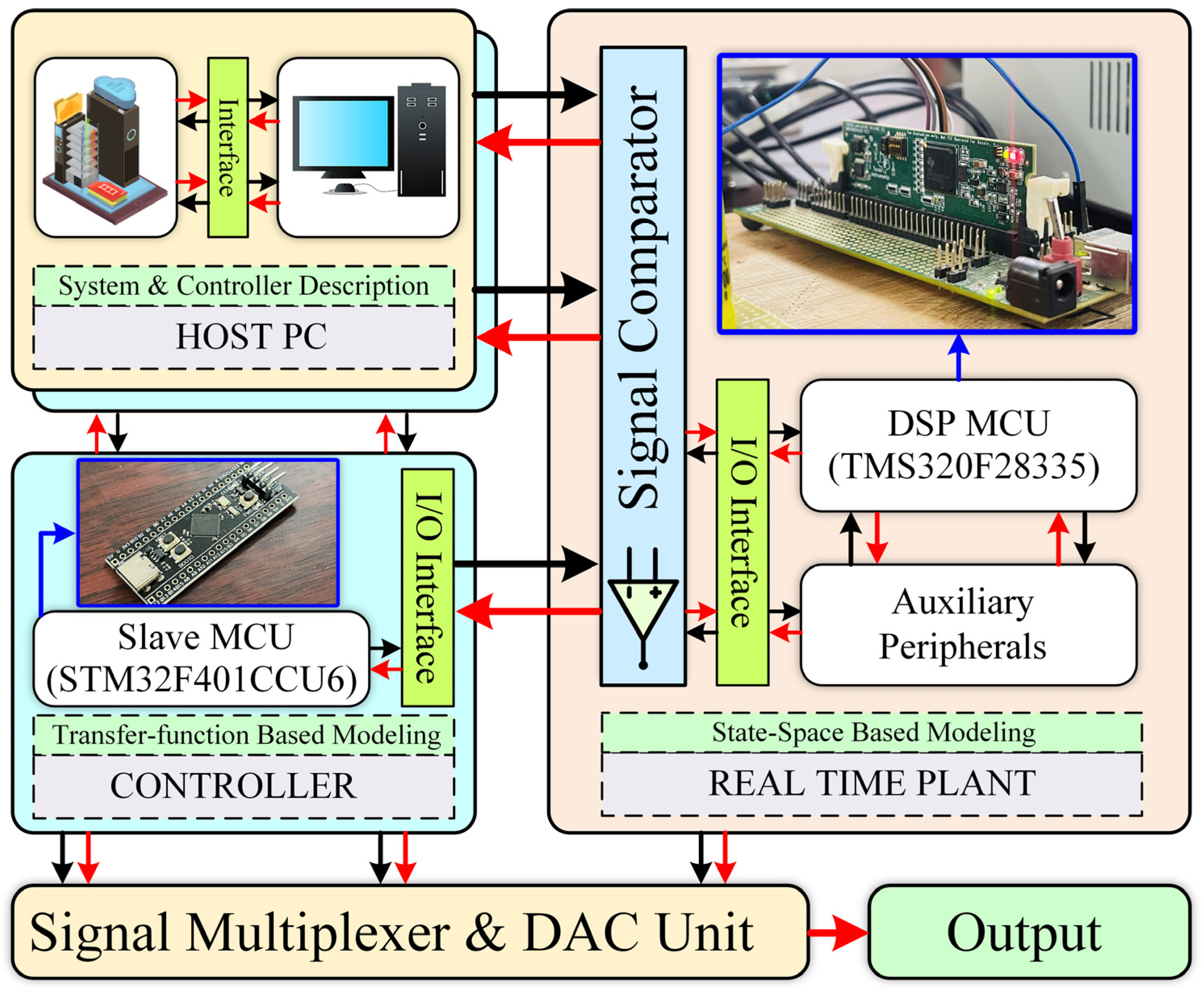
- A hybrid multiprocessor-based processor-in-loop (PIL) technique is introduced in the paper to validate the performance of the proposed control strategy; and
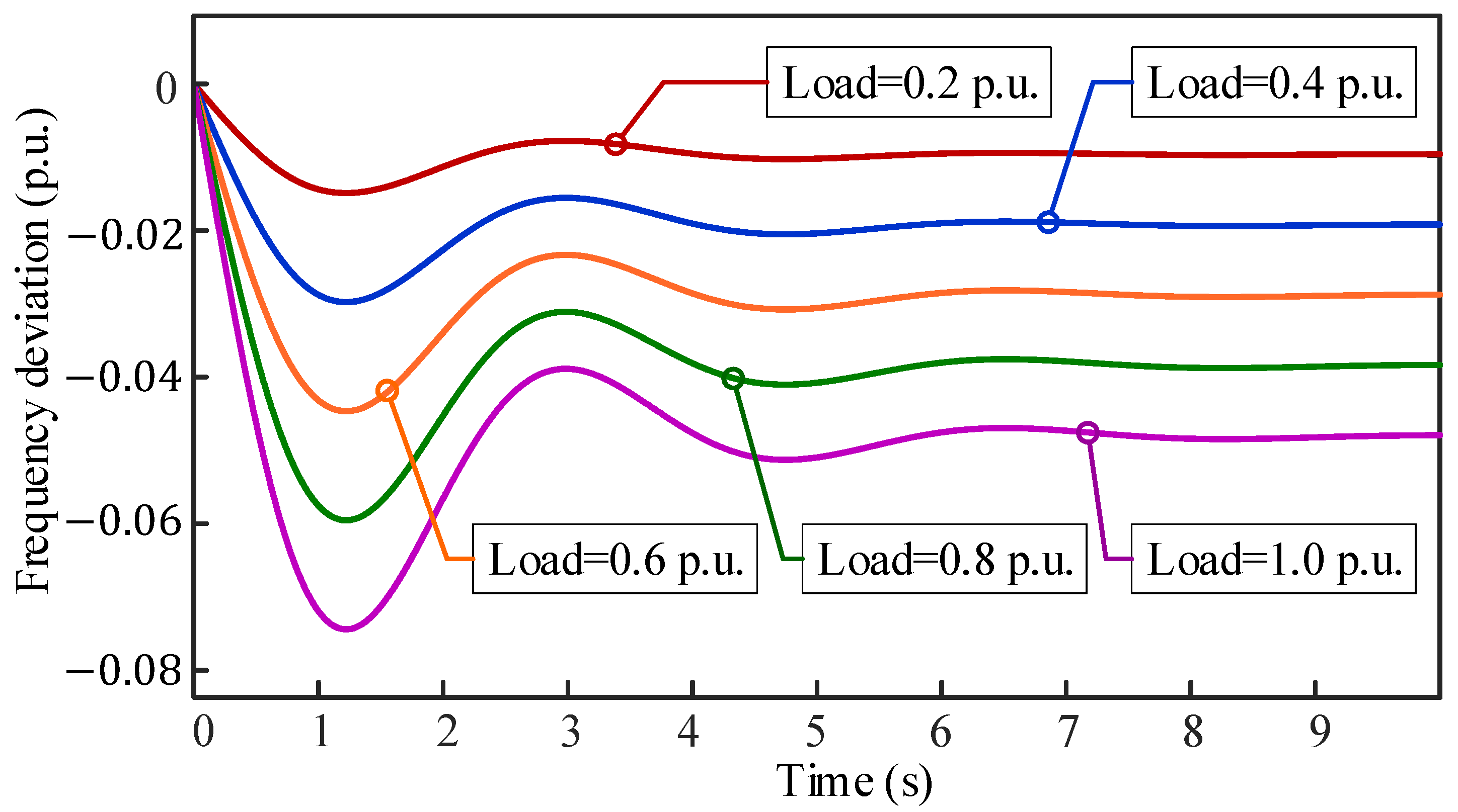
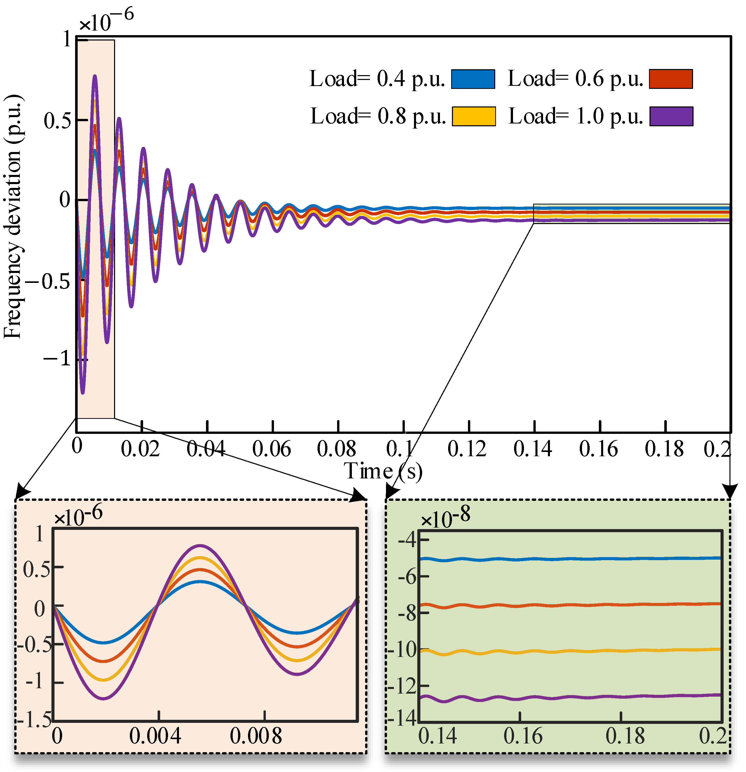
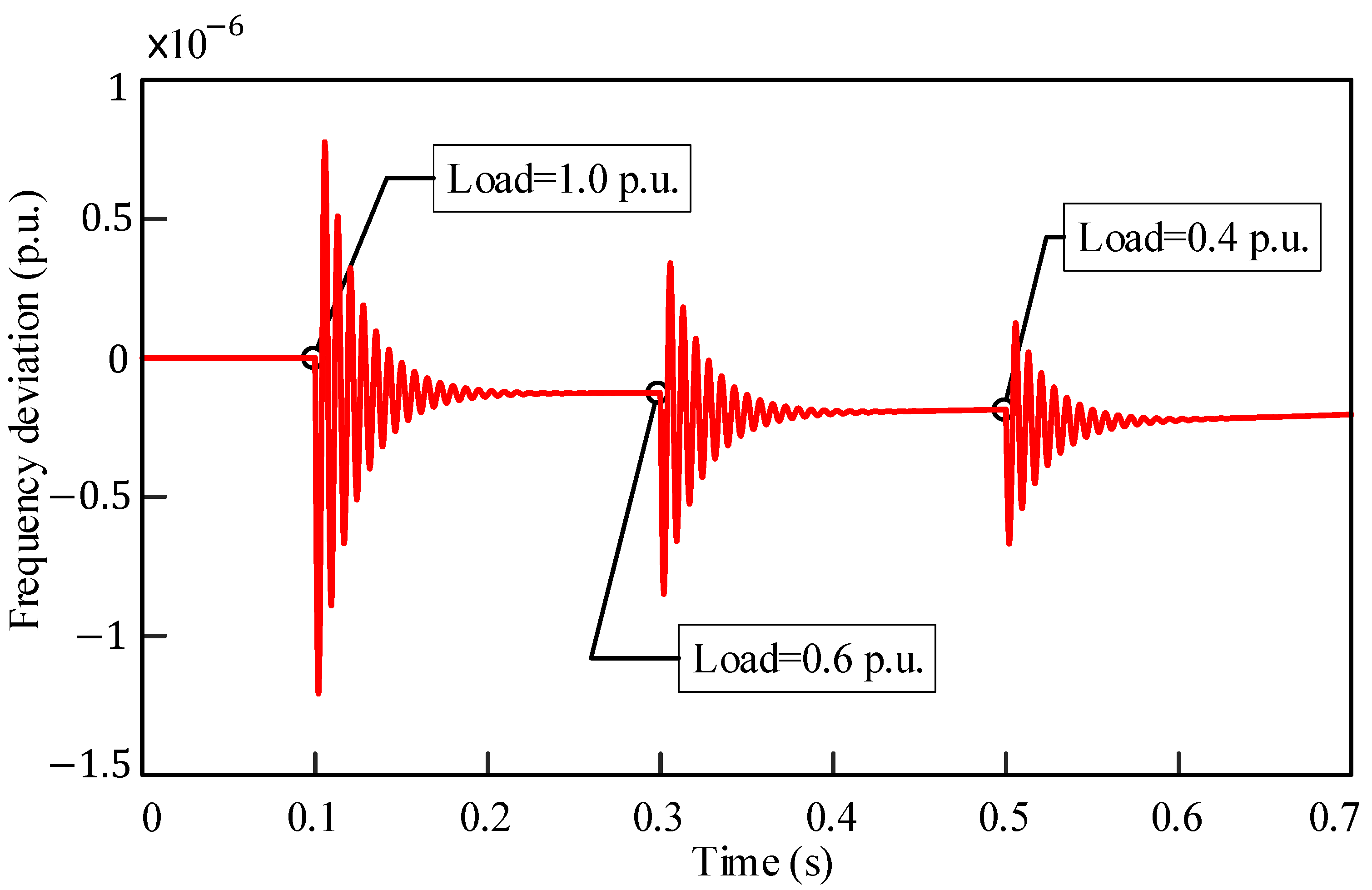
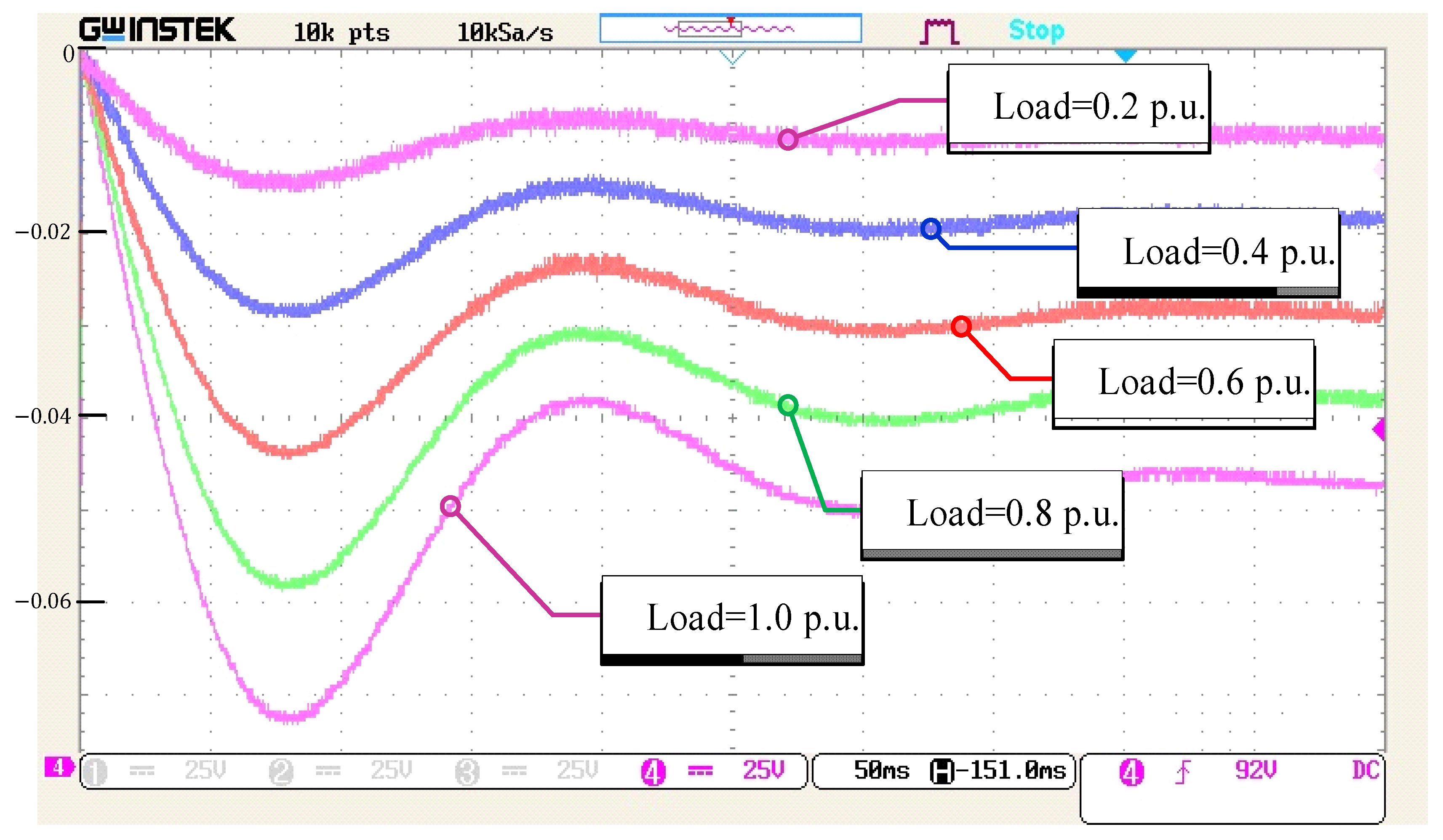
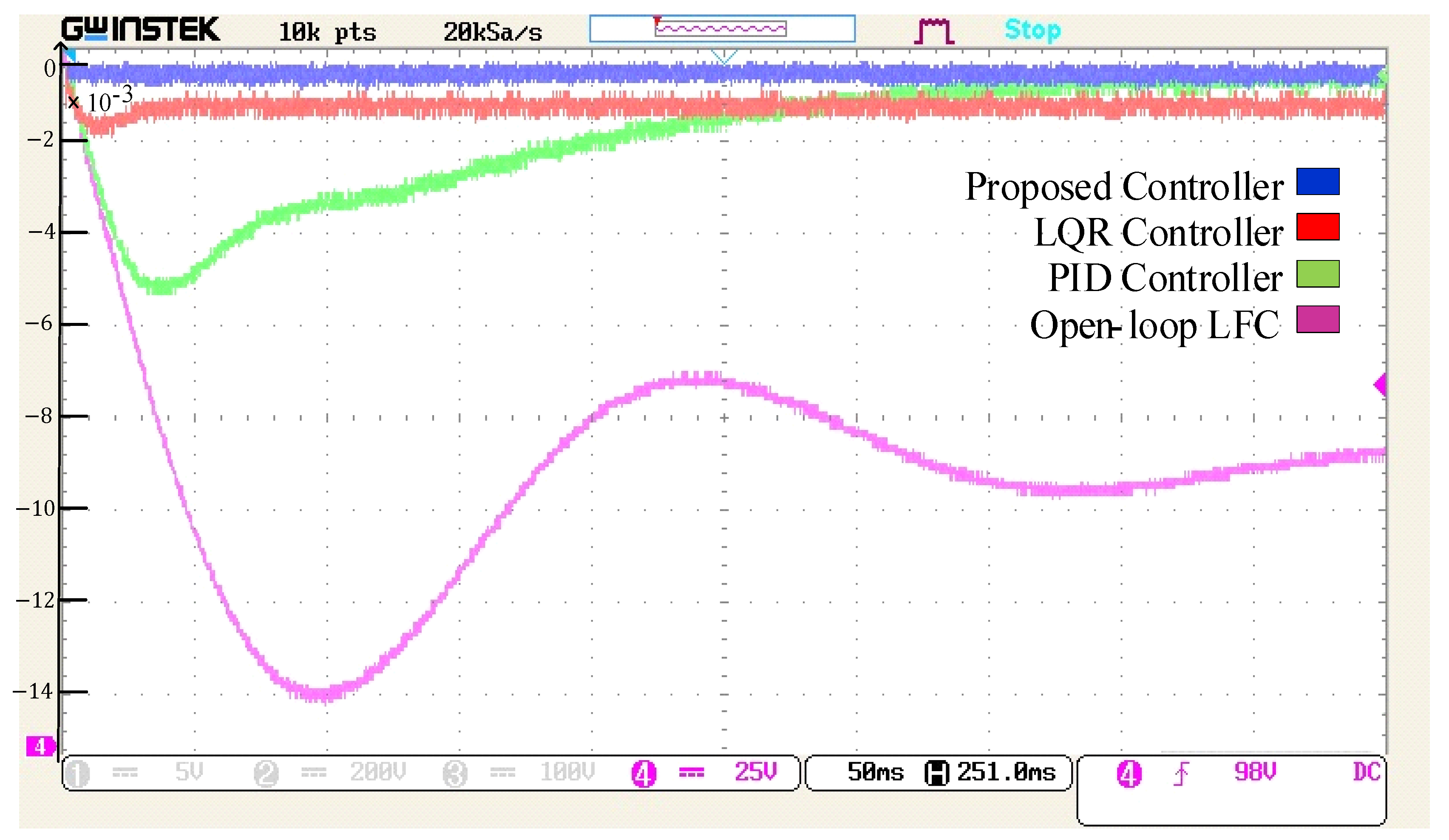
- The performance of the proposed controller is evaluated both in simulation and experimental environments in terms of frequency deviation, settling time, and steady-state error for various load conditions.
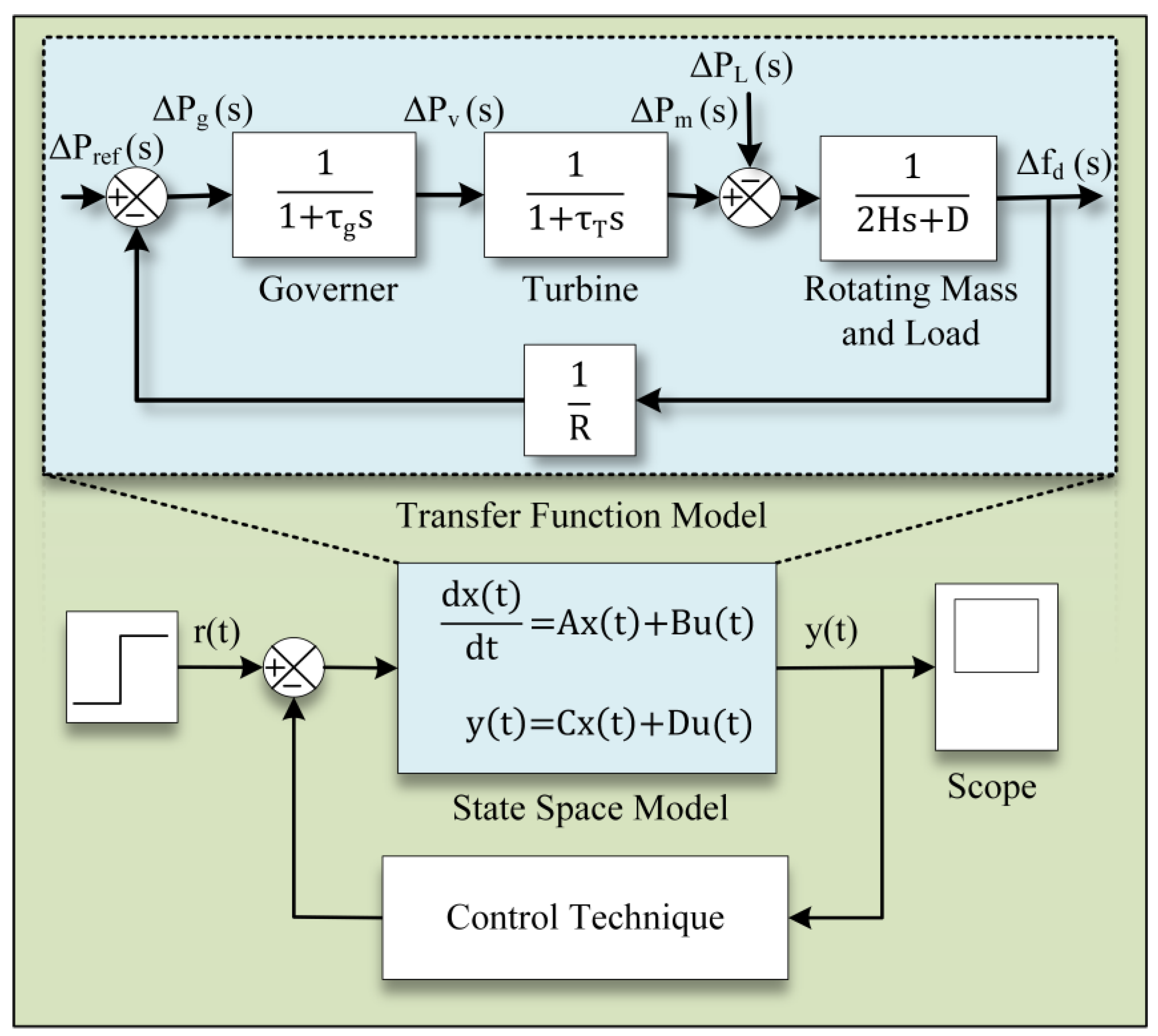
2. Modeling of the Single-Area Power System
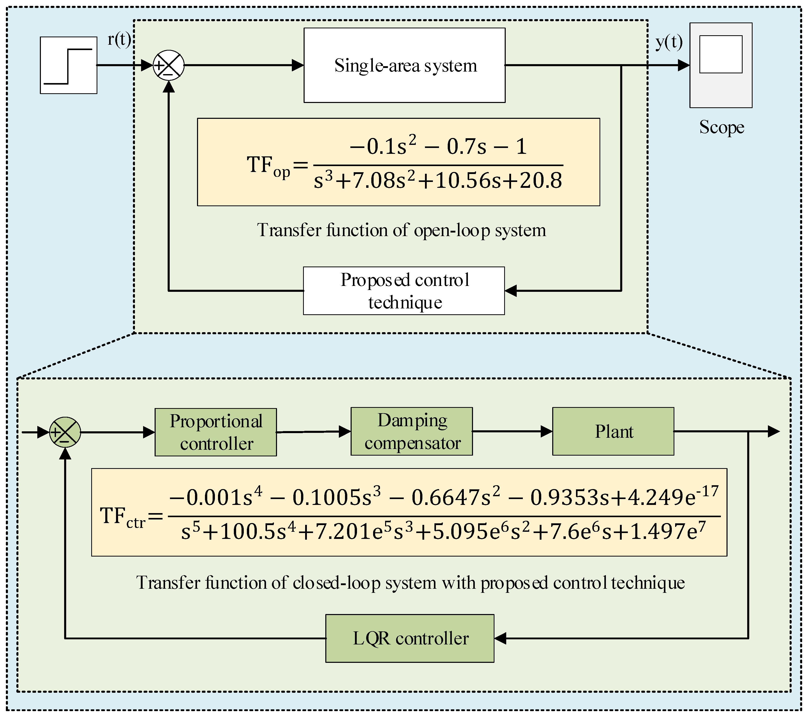
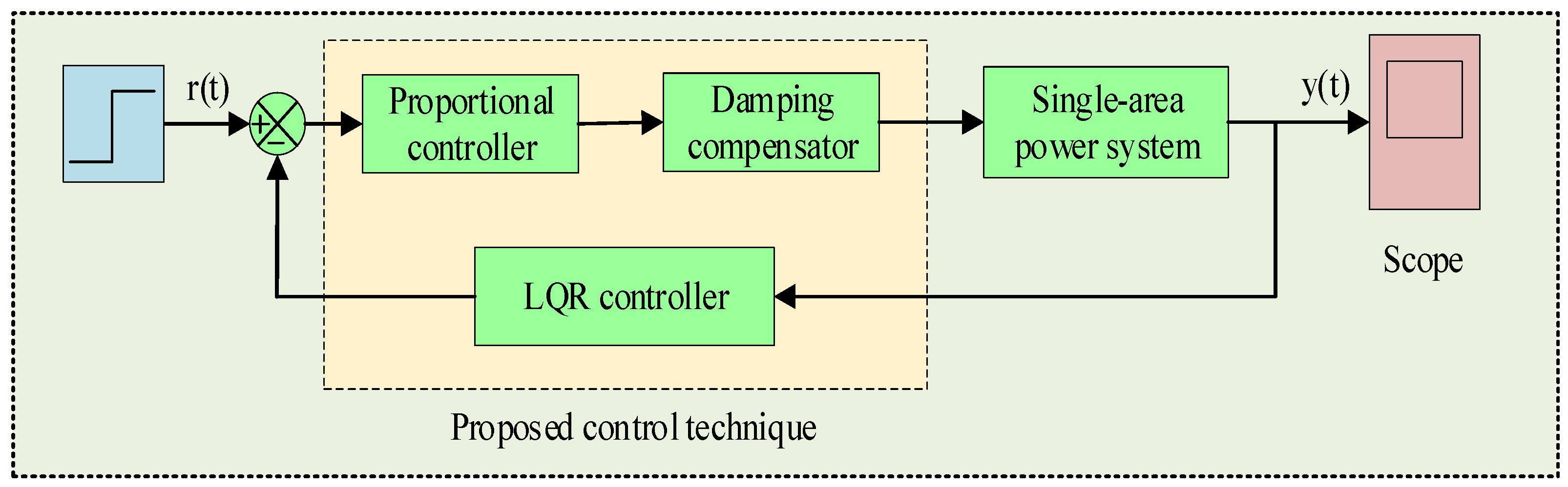
3. Design of the Proposed Controller
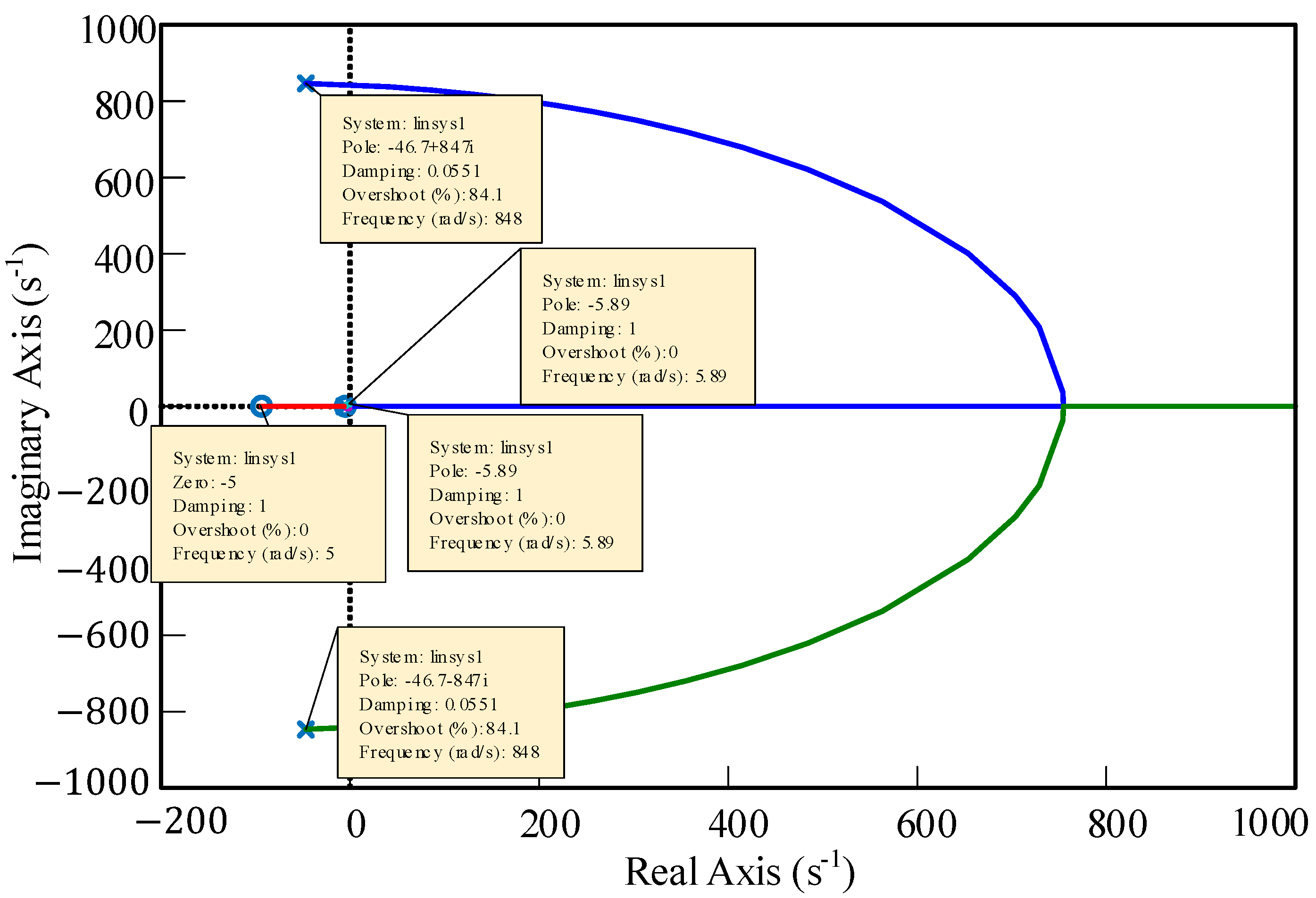
3.1. Design of the LQR
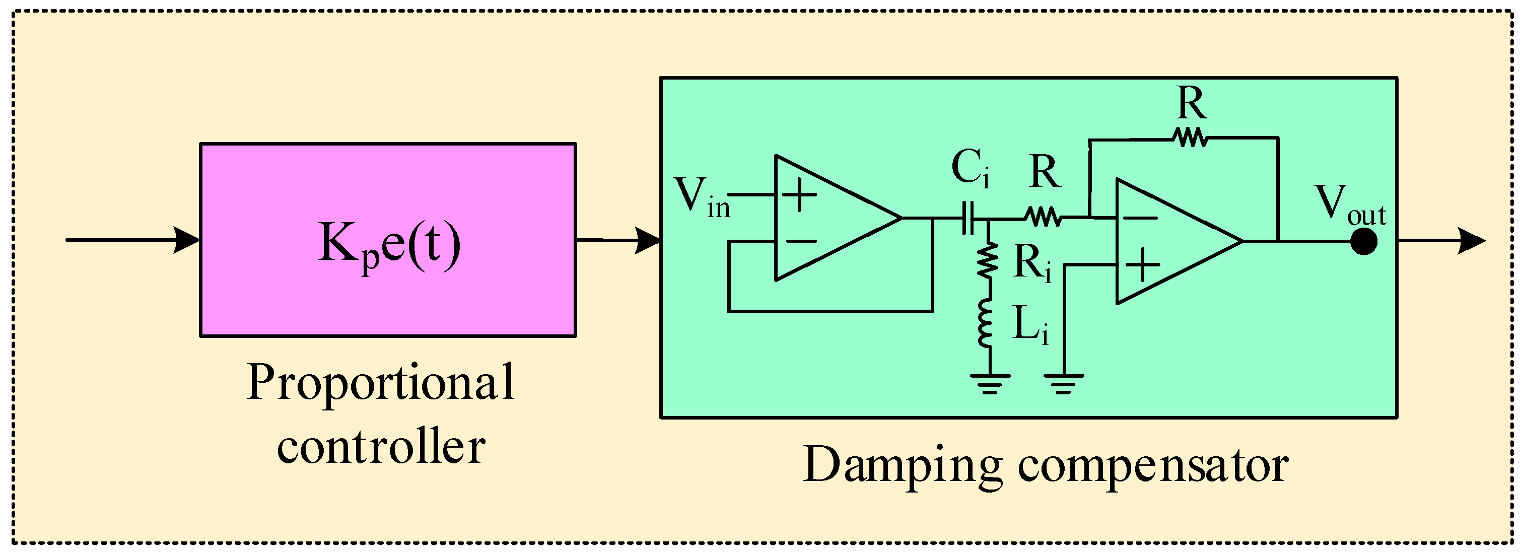
3.2. Design of the Proportional Damping Compensator
3.3. Integrating the LQR with Proportional Damping Compensator
4. Simulation Results Analysis
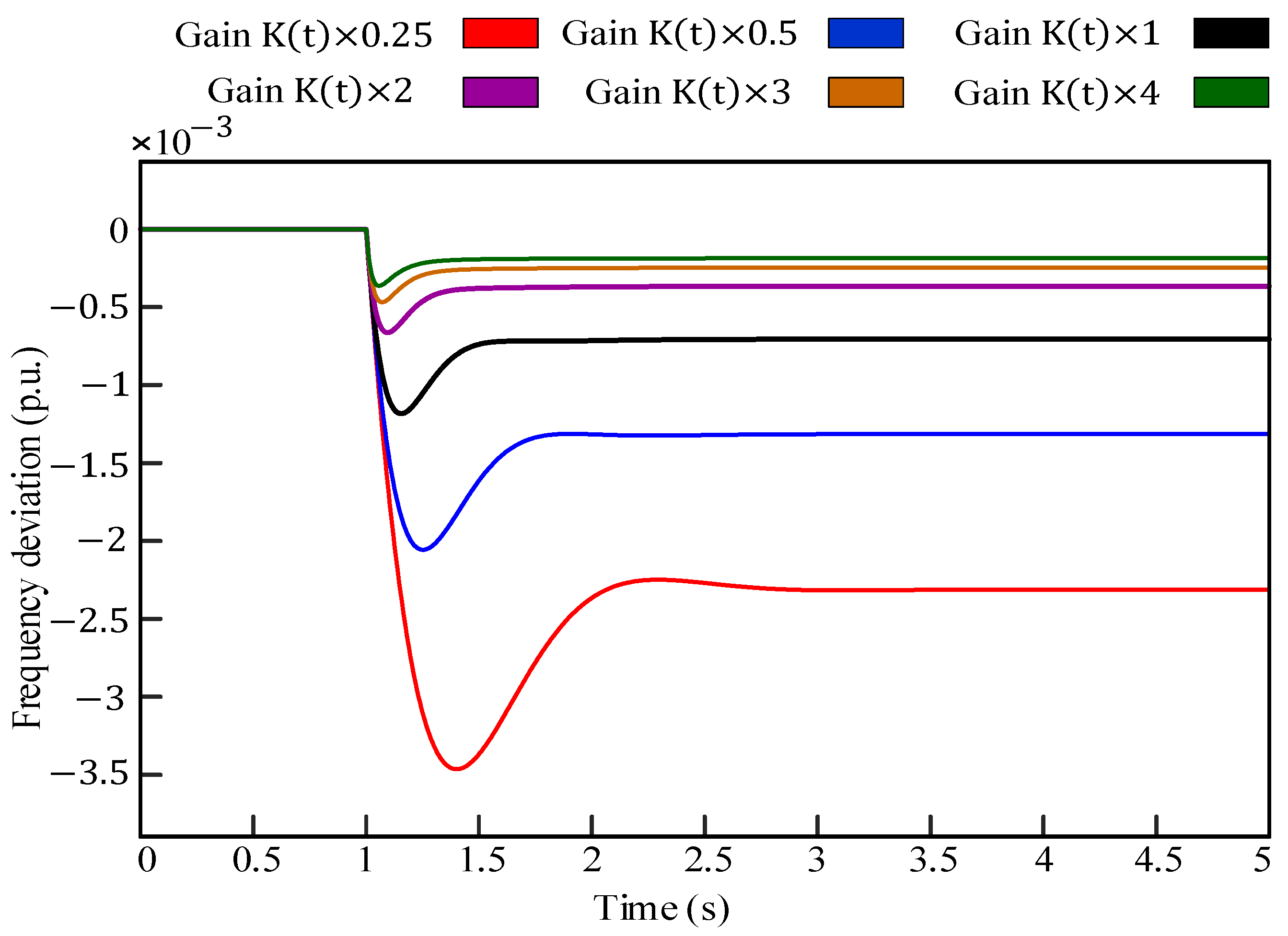
4.1. Response of the Single-Area Power System with LQR
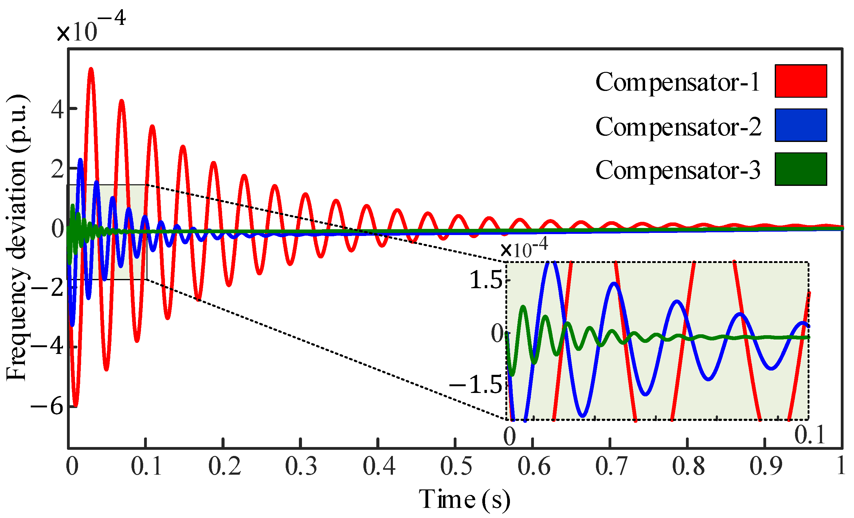
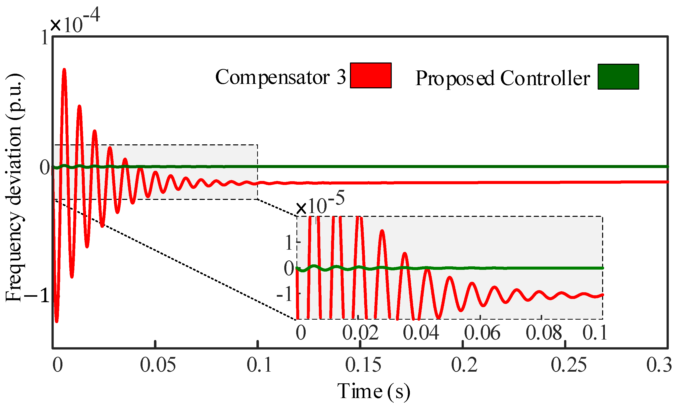
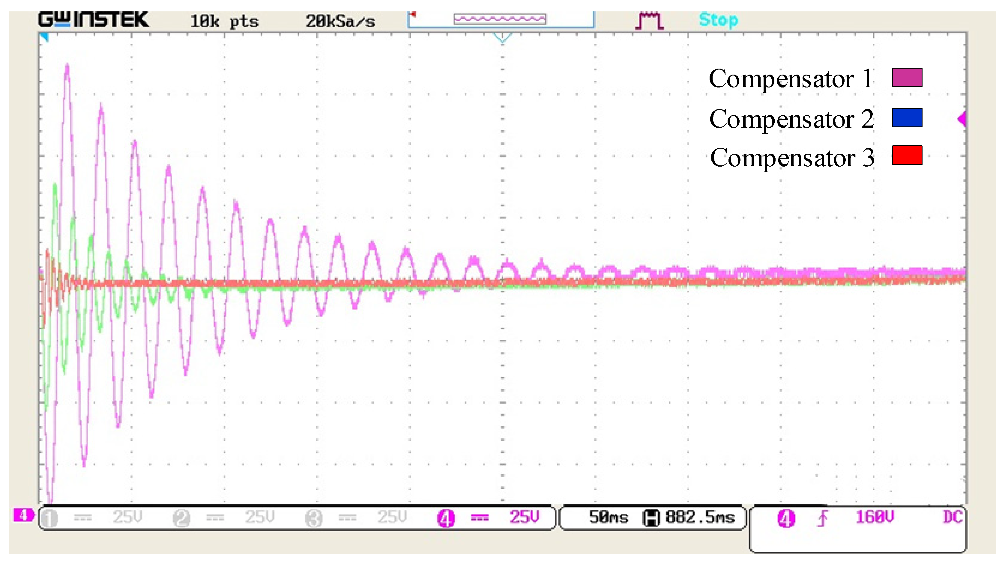
4.2. Response of the Single-Area Power System with LQR and Damping Compensator
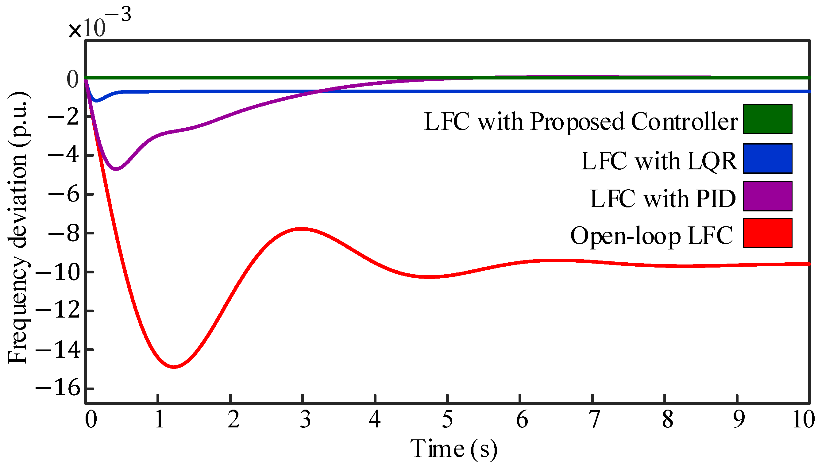
4.3. Response of the Single-Area Power System with the Proposed LQR-based Proportional Damping Compensator
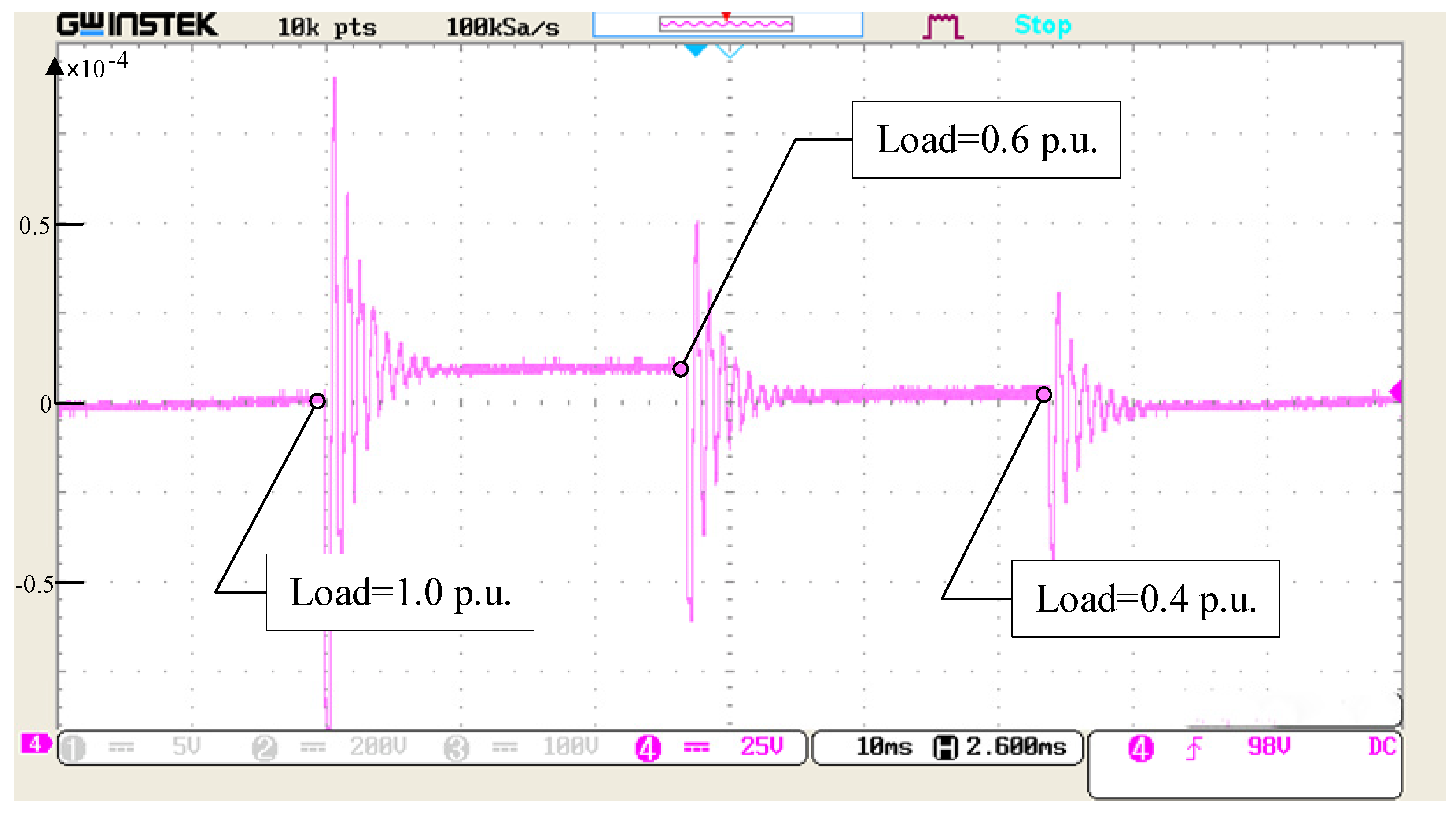
5. Experimental Analysis
6. Conclusions
Author Contributions
Funding
Data Availability Statement
Conflicts of Interest
Nomenclature
| τg | is the time constant of the governor; |
| τT | is the time constant of the turbine; |
| ΔPref | is the reference set power; |
| Δfd | is the frequency deviation; |
| ΔPL | is the load variation; |
| H | is the governor inertia constant; |
| D | is the frequency sensitive load coefficient; |
| R | is the speed regulation of the governor; |
| Abbreviations | |
| LFC | Load frequency control |
| AGC | Automatic generation control |
| PIL | Processor-in-loop |
| LQR | Linear quadratic regulator |
| SG | Synchronous generator |
| PID | Proportional–integral–derivative |
| MPC | Model predictive control |
| SMC | Sliding mode control |
| ANN | Artificial neural networks |
| EID | Equivalent input disturbances |
| ADRC | Active disturbance rejection control |
| SOPTD | Second order plus time delay |
| FOPID | Fractional-order proportional–integral–derivative |
References
- Fusco, G.; Russo, M. Adaptive voltage regulator design for synchronous generator. IEEE Trans. Energy Convers. 2008, 23, 946–956. [Google Scholar] [CrossRef]
- Rajamand, S. Load Frequency Control and Dynamic Response Improvement Using Energy Storage and Modeling of Uncertainty in Renewable Distributed Generators. J. Energy Storage 2021, 37, 102467. [Google Scholar] [CrossRef]
- Tan, K.M.; Babu, T.S.; Ramachandaramurthy, V.K.; Kasinathan, P.; Solanki, S.G.; Raveendran, S.K. Empowering smart grid: A comprehensive review of energy storage technology and application with Renewable Energy Integration. J. Energy Storage 2021, 39, 102591. [Google Scholar] [CrossRef]
- Ranjan, M.; Shankar, R. A literature survey on load frequency control considering renewable energy integration in power system: Recent trends and future prospects. J. Energy Storage 2022, 45, 103717. [Google Scholar] [CrossRef]
- Dokht Shakibjoo, A.; Moradzadeh, M.; Moussavi, S.Z.; Vandevelde, L. A novel technique for load frequency control of Multi-Area Power Systems. Energies 2020, 13, 2125. [Google Scholar] [CrossRef]
- Pandey, S.K.; Gupta, P.; Dwivedi, S.S. Full order observer-based load frequency control of Single Area Power System. In Proceedings of the 2020 12th International Conference on Computational Intelligence and Communication Networks (CICN), Bhimtal, India, 25–26 September 2020. [Google Scholar]
- Dehuri, P.; Hote, Y.V. Indirect IMC based PID controller design for single area LFC system in the presence of uncertainty and communication delay. In Proceedings of the 2021 IEEE Texas Power and Energy Conference (TPEC), College Station, TX, USA, 2–5 February 2021. [Google Scholar]
- Khan, M.; Sun, H. Complete Provision of MPC-Based LFC By Electric Vehicles With Inertial and Droop Support from DFIG-Based Wind Farm. IEEE Trans. Power Deliv. 2022, 37, 716–726. [Google Scholar] [CrossRef]
- Zhong, Q.; Yang, J.; Shi, K.; Zhong, S.; Li, Z.; Sotelo, M.A. Event-Triggered H∞ Load Frequency Control for Multi-Area Nonlinear Power Systems Based on Non-Fragile Proportional Integral Control Strategy. IEEE Trans. Intell. Transp. Syst. 2022, 23, 12191–12201. [Google Scholar] [CrossRef]
- Ali, H.H.; Fathy, A.; Al-Shaalan, A.M.; Kassem, A.M.; Farh, H.M.H.; Al-Shamma’a, A.A.; Gabbar, H.A. A novel sooty terns algorithm for deregulated MPC-LFC installed in multi-interconnected system with renewable energy plants. Energies 2021, 14, 5393. [Google Scholar] [CrossRef]
- Mercader, P.; Åström, K.J.; Baños, A.; Hägglund, T. Robust PID Design Based on QFT and Conve Concave Optimization. IEEE Trans. Control. Syst. Technol. 2017, 25, 441–452. [Google Scholar] [CrossRef]
- Chen, B.-Y.; Shangguan, X.-C.; Jin, L.; Li, D.-Y. An improved stability criterion for load frequency control of power systems with time-varying delays. Energies 2020, 13, 2101. [Google Scholar] [CrossRef]
- Liu, F.; Zhang, K.; Zou, R. Robust LFC Strategy for Wind Integrated Time-Delay Power System Using EID Compensation. Energies 2019, 12, 3223. [Google Scholar] [CrossRef]
- Kumar, A.; Pan, S. Design of fractional order PID controller for load frequency control system with communication delay. ISA Trans. 2022, 129, 138–149. [Google Scholar] [CrossRef]
- Alayi, R.; Zishan, F.; Seyednouri, S.R.; Kumar, R.; Ahmadi, M.H.; Sharifpur, M. Optimal load frequency control of island microgrids via a PID controller in the presence of wind turbine and PV. Sustainability 2021, 13, 10728. [Google Scholar] [CrossRef]
- Liu, X.; Qiao, S.; Liu, Z. A survey on load frequency control of multi-area power systems: Recent challenges and Strategies. Energies 2023, 16, 2323. [Google Scholar] [CrossRef]
- Yerolla, R.; Bestha, C.S. PI/PID controller design for critically damped SOPTD system and experimental validation. In Proceedings of the 2021 5th International Conference on Intelligent Computing and Control Systems, Madurai, India, 6–8 May 2021; pp. 531–535. [Google Scholar]
- Mani, P.; Joo, Y.H. Fuzzy logic-based integral sliding mode control of multi-area power systems integrated with wind farms. Inf. Sci. 2021, 545, 153–169. [Google Scholar] [CrossRef]
- Liu, X.; Bai, D.; Qiao, S.; Xiao, G.; Ge, S.S. Resilient and event-triggered sliding mode load frequency control for multi-area power systems under hybrid cyber attacks. IET Control Theory Appl. 2022, 16, 1739–1750. [Google Scholar] [CrossRef]
- Sun, Y.; Wang, Y.; Wei, Z.; Sun, Z.; Wu, X. Robust H∞ load frequency control of multi-area power system with time delay: A sliding mode control approach. IEEE/CAA J. Autom. Sin. 2017, 5, 610–617. [Google Scholar] [CrossRef]
- Hossam-Eldin, A.; Mostafa, H.; Kotb, H.; AboRas, K.M.; Selim, A.; Kamel, S. Improving the frequency response of hybrid microgrid under renewable sources’ uncertainties using a robust LFC-based African vulture optimization algorithm. Processes 2022, 10, 2320. [Google Scholar] [CrossRef]
- Coban, H.H.; Rehman, A.; Mousa, M. Load frequency control of microgrid system by battery and pumped-hydro energy storage. Water 2022, 14, 1818. [Google Scholar] [CrossRef]
- Alaei, H.K.; Yazdizadeh, A.; Aliabadi, A. Nonlinear predictive controller design for load frequency control in power system using quasi newton optimization approach. In Proceedings of the IEEE International Conference on Control Applications (CCA), Hyderabad, India, 28–30 August 2013; pp. 679–684. [Google Scholar]
- Jamil, A.A.; Tu, W.F.; Ali, S.W.; Terriche, Y.; Guerrero, J.M. Fractional-order PID controllers for Temperature Control: A Review. Energies 2022, 15, 3800. [Google Scholar] [CrossRef]
- Ferahtia, S.; Djeroui, A.; Mesbahi, T.; Houari, A.; Zeghlache, S.; Rezk, H.; Paul, T. Optimal adaptive gain LQR-based Energy Management Strategy for Battery–Supercapacitor Hybrid Power System. Energies 2021, 14, 1660. [Google Scholar] [CrossRef]
- Sibilska-Mroziewicz, A.; Ordys, A.; Możaryn, J.; Alinaghi Hosseinabadi, P.; Soltani Sharif Abadi, A.; Pota, H. LQR and Fuzzy Logic Control for the three-area power system. Energies 2021, 14, 8522. [Google Scholar] [CrossRef]
- Tan, W.; Xu, Z. Robust analysis and design of Load Frequency Controller for Power Systems. Electr. Power Syst. Res. 2009, 79, 846–853. [Google Scholar] [CrossRef]
- Pota, H.R.; Moheimani, S.O.; Smith, M. Resonant controllers for smart structures. Smart Mater. Struct. 2002, 11, 1–8. [Google Scholar] [CrossRef]


| Controller Technique | Frequency Deviation (p.u.) | Settling Time (s) | Steady-State Error (p.u.) |
|---|---|---|---|
| Open loop | 15 × 10−3 | 10 | 9.58 × 10⁻³ |
| PID [9] | 4.8 × 10⁻³ | 6 | 0 |
| LQR [10] | 11.9 × 10⁻⁴ | 0.7 | 7.052 × 10⁻⁴ |
| Legendre function [10] | 6 × 10⁻⁴ | 0.6 | 1 × 10⁻⁵ |
| Proposed controller | 2 × 10⁻⁶ | 0.15 | 2.83 × 10⁻⁷ |
Disclaimer/Publisher’s Note: The statements, opinions and data contained in all publications are solely those of the individual author(s) and contributor(s) and not of MDPI and/or the editor(s). MDPI and/or the editor(s) disclaim responsibility for any injury to people or property resulting from any ideas, methods, instructions or products referred to in the content. |
© 2023 by the authors. Licensee MDPI, Basel, Switzerland. This article is an open access article distributed under the terms and conditions of the Creative Commons Attribution (CC BY) license (https://creativecommons.org/licenses/by/4.0/).
Share and Cite
Das, P.; Biswas, S.P.; Mondal, S.; Islam, M.R. Frequency Fluctuation Mitigation in a Single-Area Power System Using LQR-Based Proportional Damping Compensator. Energies 2023, 16, 4804. https://doi.org/10.3390/en16124804
Das P, Biswas SP, Mondal S, Islam MR. Frequency Fluctuation Mitigation in a Single-Area Power System Using LQR-Based Proportional Damping Compensator. Energies. 2023; 16(12):4804. https://doi.org/10.3390/en16124804
Chicago/Turabian StyleDas, Pranta, Shuvra Prokash Biswas, Sudipto Mondal, and Md Rabiul Islam. 2023. "Frequency Fluctuation Mitigation in a Single-Area Power System Using LQR-Based Proportional Damping Compensator" Energies 16, no. 12: 4804. https://doi.org/10.3390/en16124804
APA StyleDas, P., Biswas, S. P., Mondal, S., & Islam, M. R. (2023). Frequency Fluctuation Mitigation in a Single-Area Power System Using LQR-Based Proportional Damping Compensator. Energies, 16(12), 4804. https://doi.org/10.3390/en16124804