
Loads Calculation and Strength Calculation of Landing String during Deepwater Drilling

Abstract
:1. Introduction
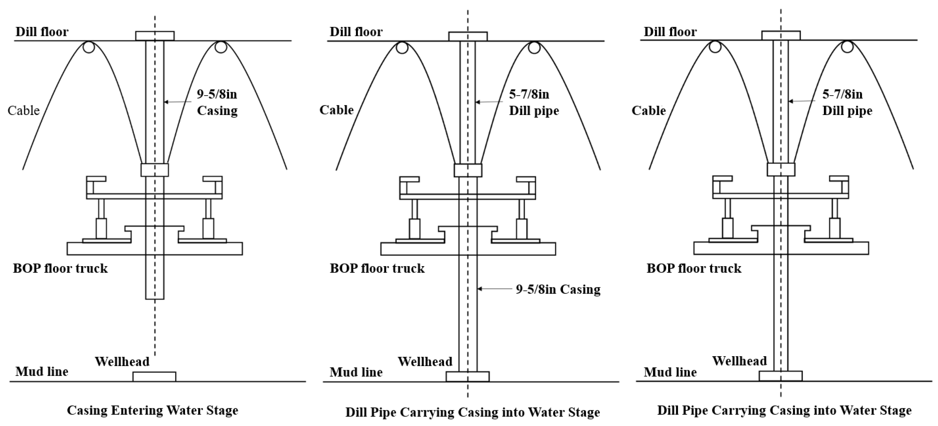
2. Stage Analysis
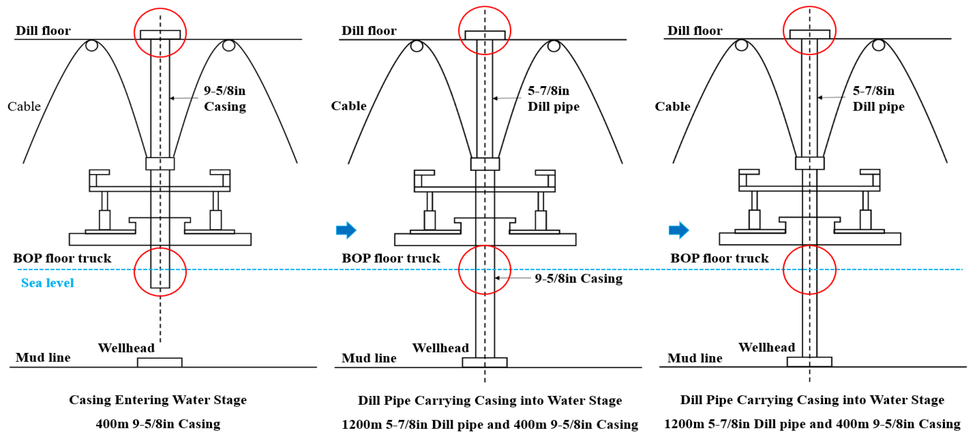
2.1. Casing Entering Water Stage
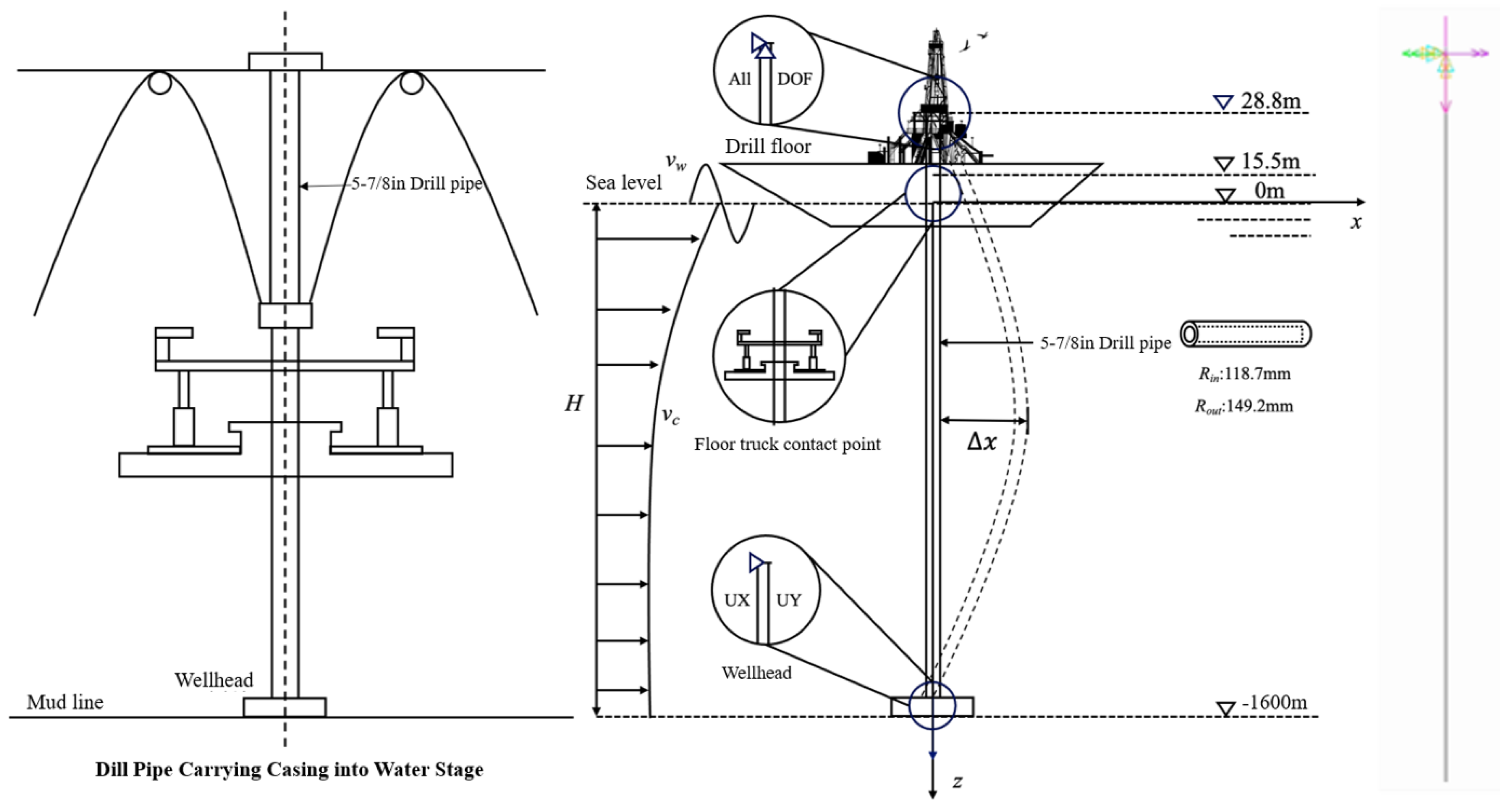
2.2. Drill Pipe Carrying Casing into Water Stage
2.3. Drill Pipe Carrying Casing into Wellhead Stage
3. Load Analysis
3.1. Dangerous Point Analysis of the String
3.2. Marine Environmental Load Analysis
4. Basic Parameters
4.1. String Parameters
4.2. Wind and Current Internal Wave Parameters
4.3. Hydrodynamic Parameters
5. Calculation and Check
5.1. Calculation Method of Static Tensile Load of String
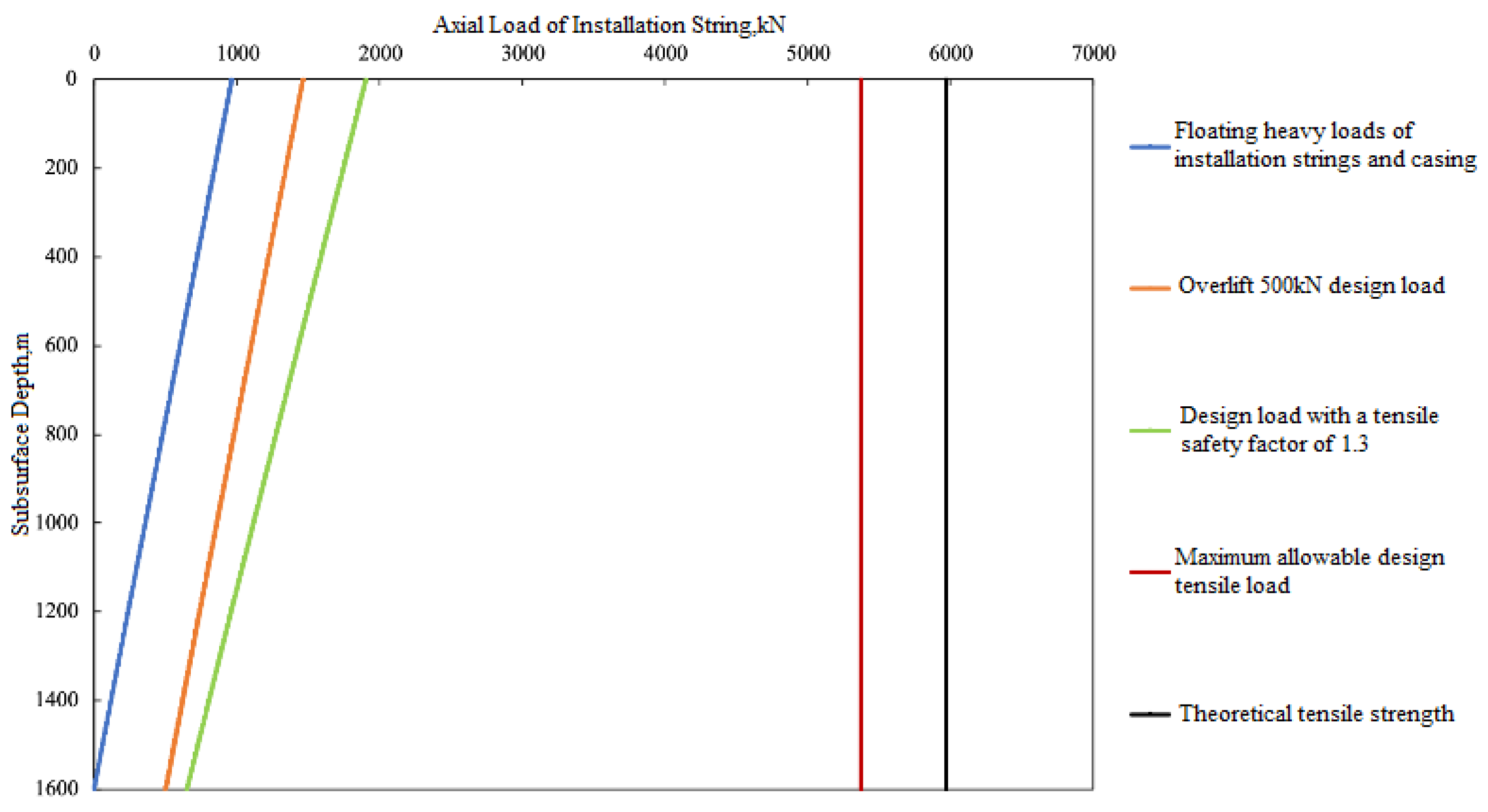
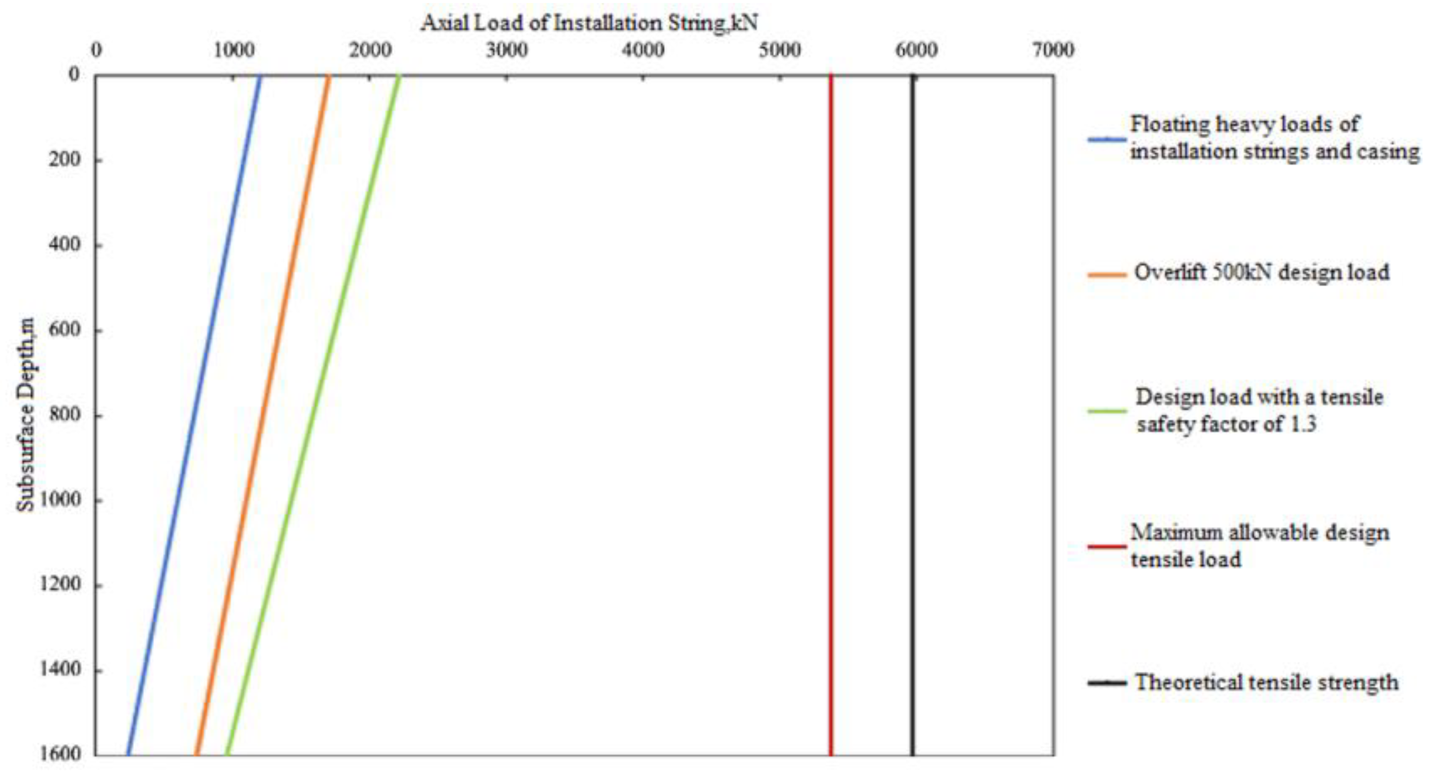
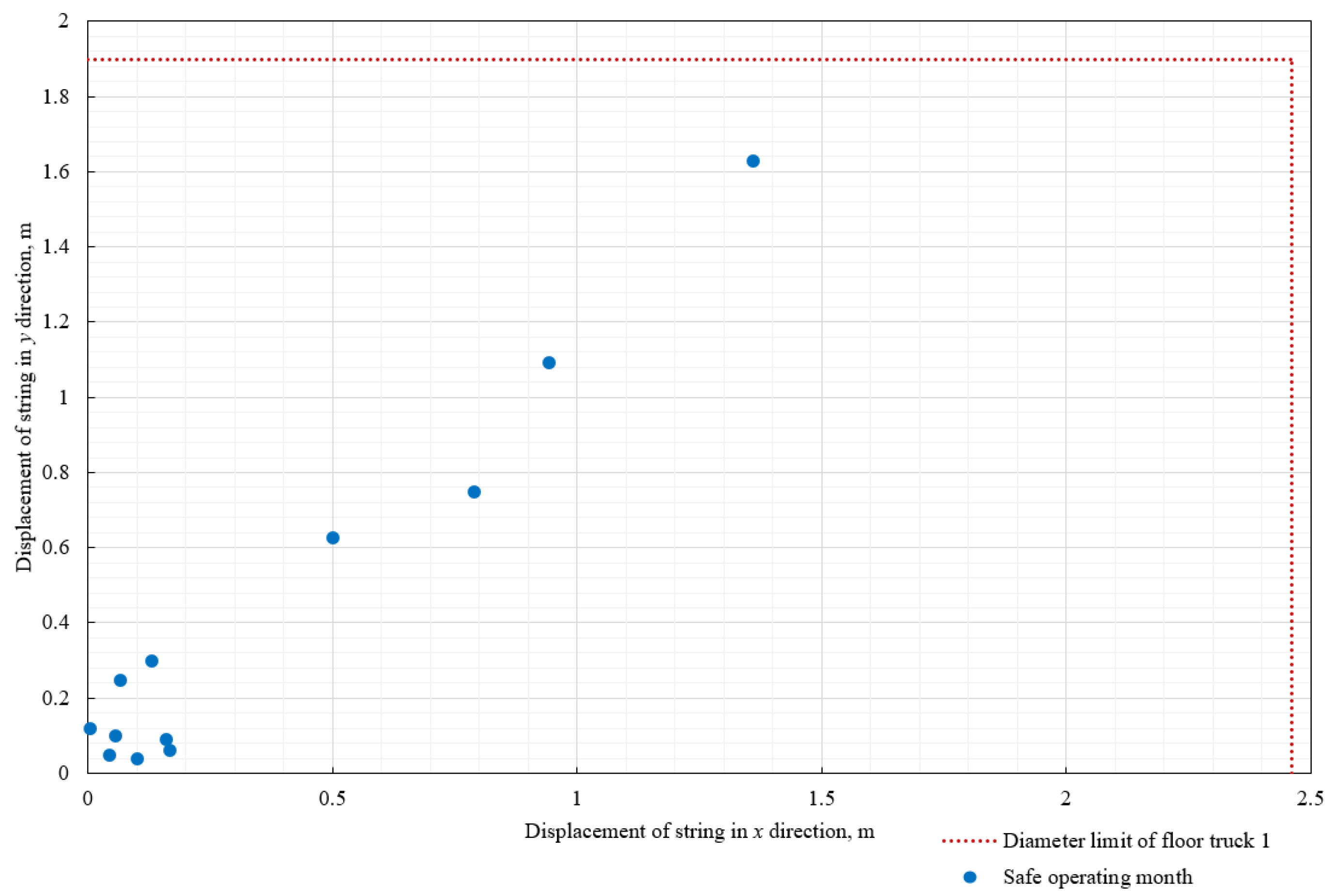
5.2. Design of Checking the Static Tensile Load of the String
5.3. Strength Check of Casing Entering Water Stage
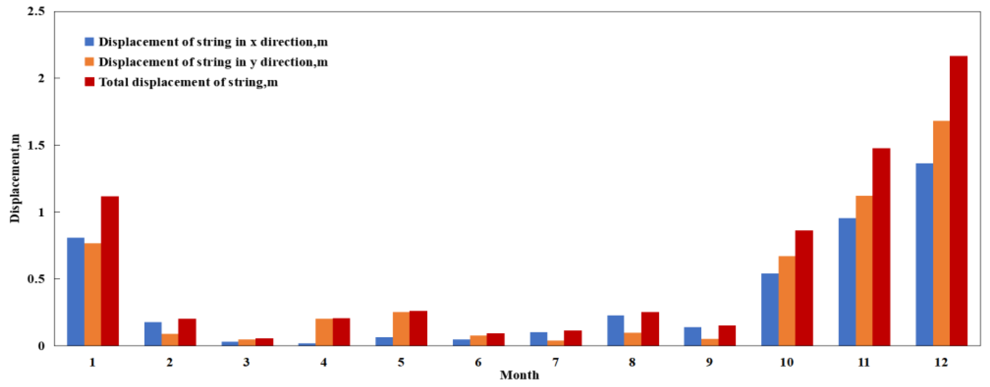
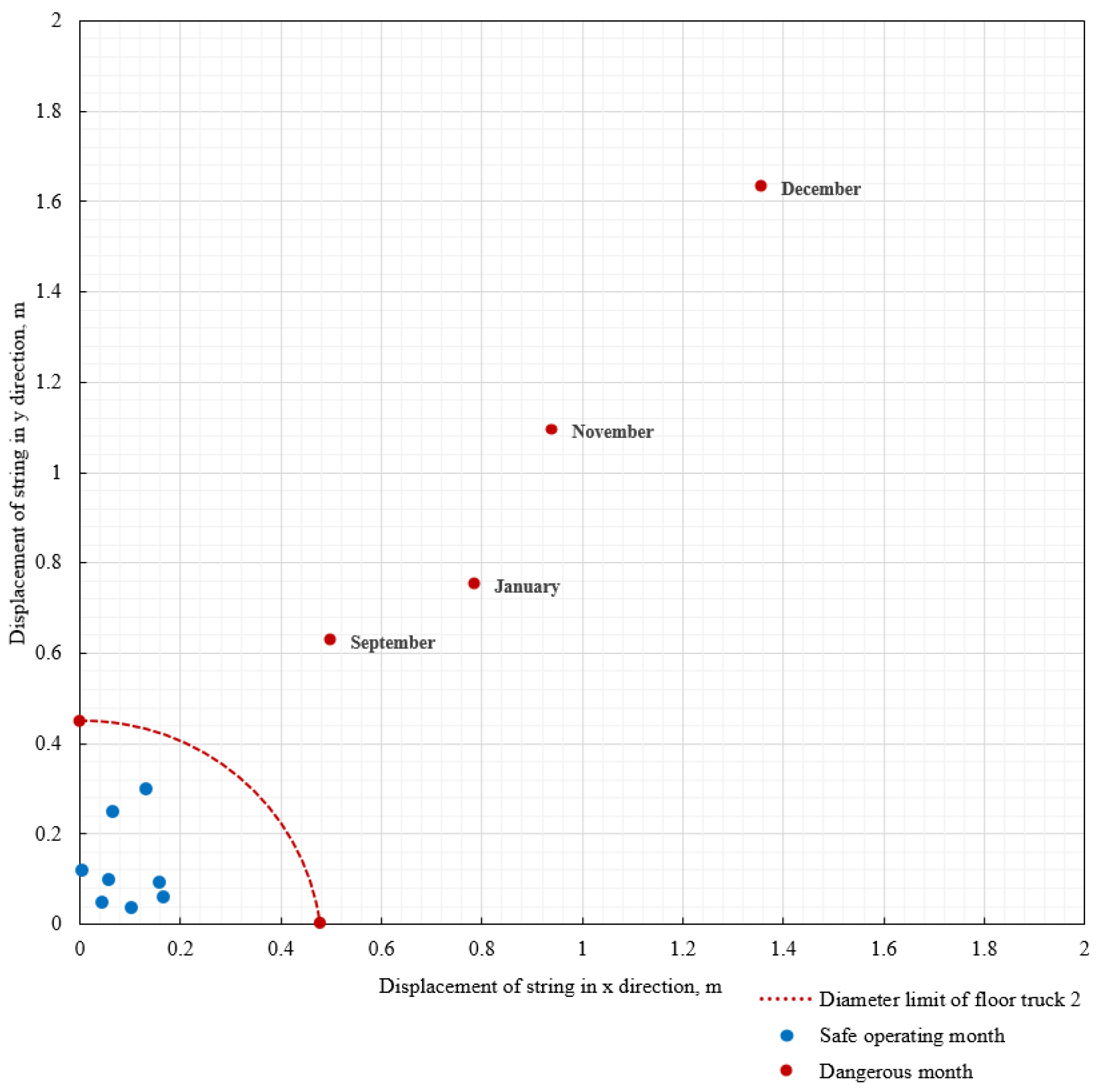
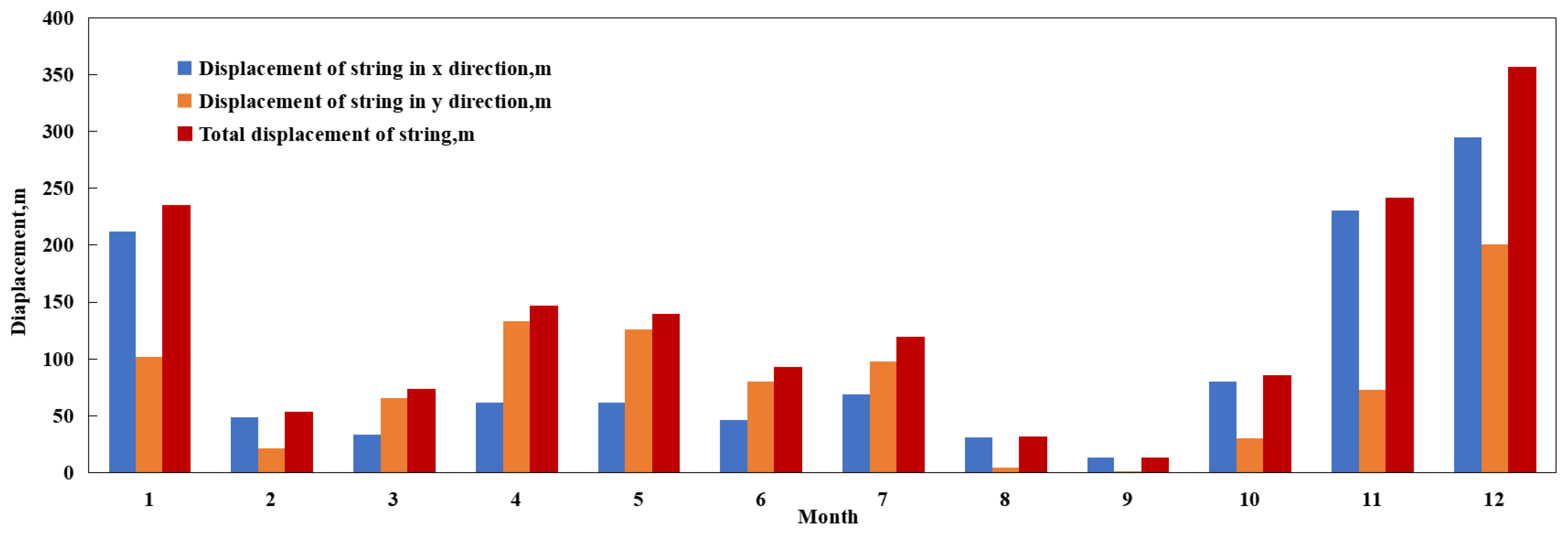
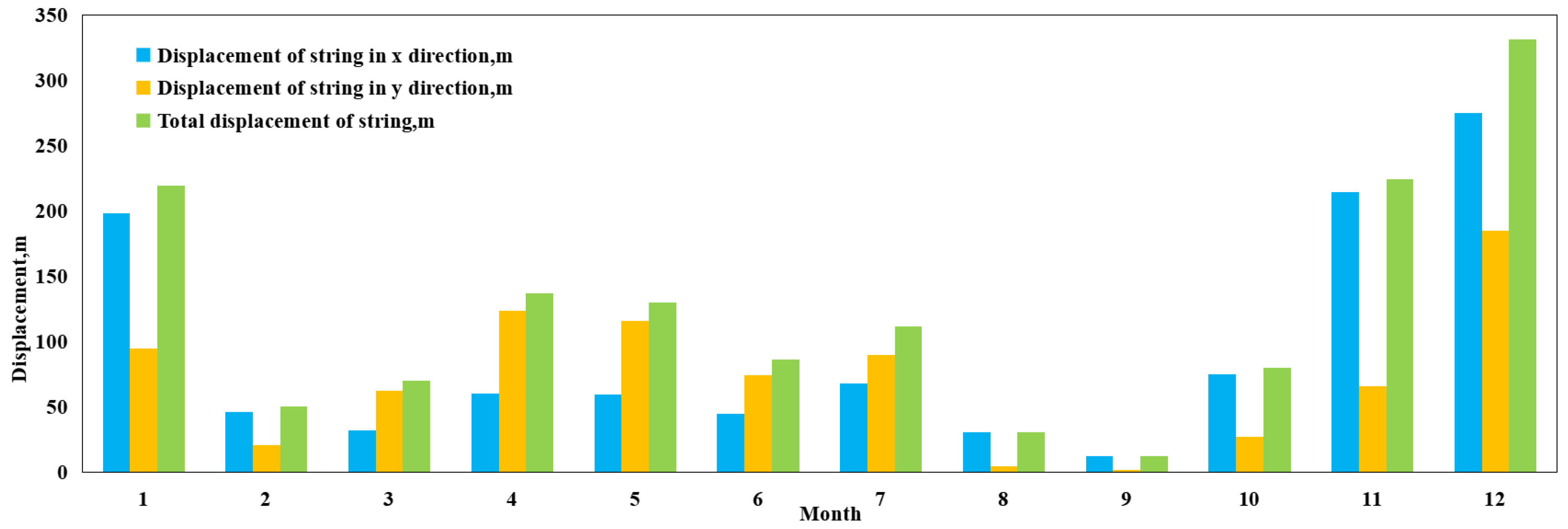
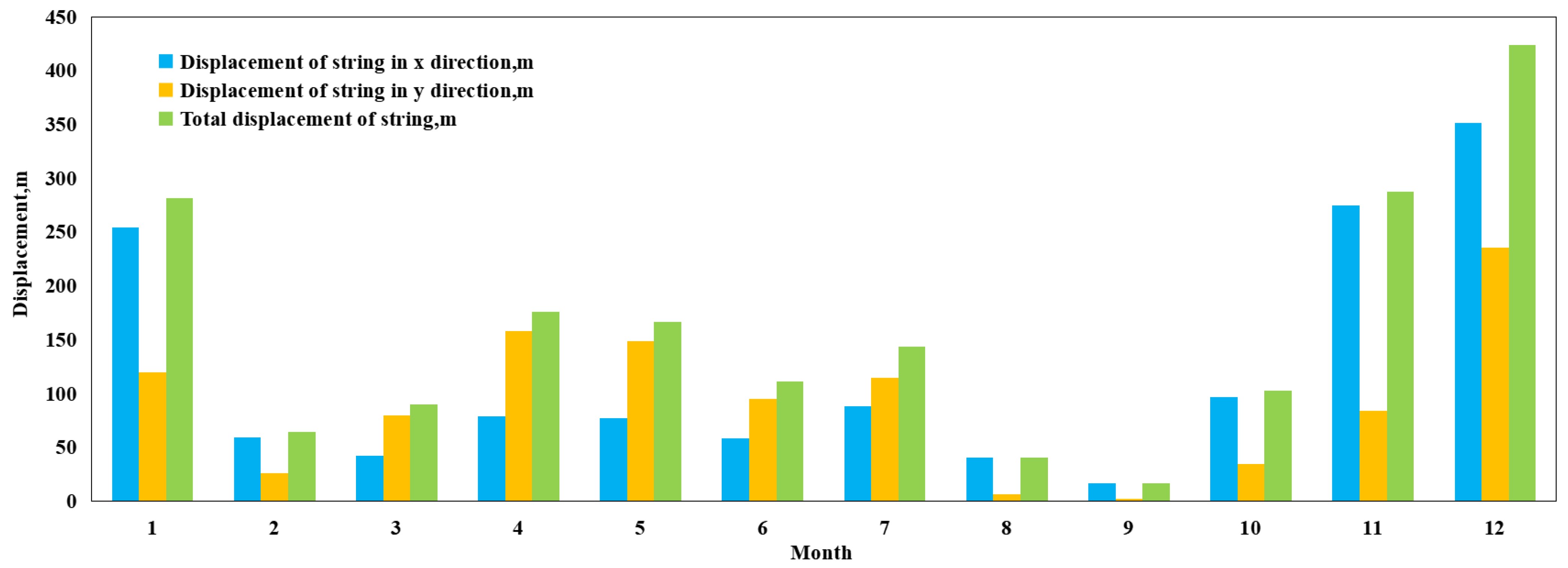
5.3.1. Calculation of Lateral Displacement
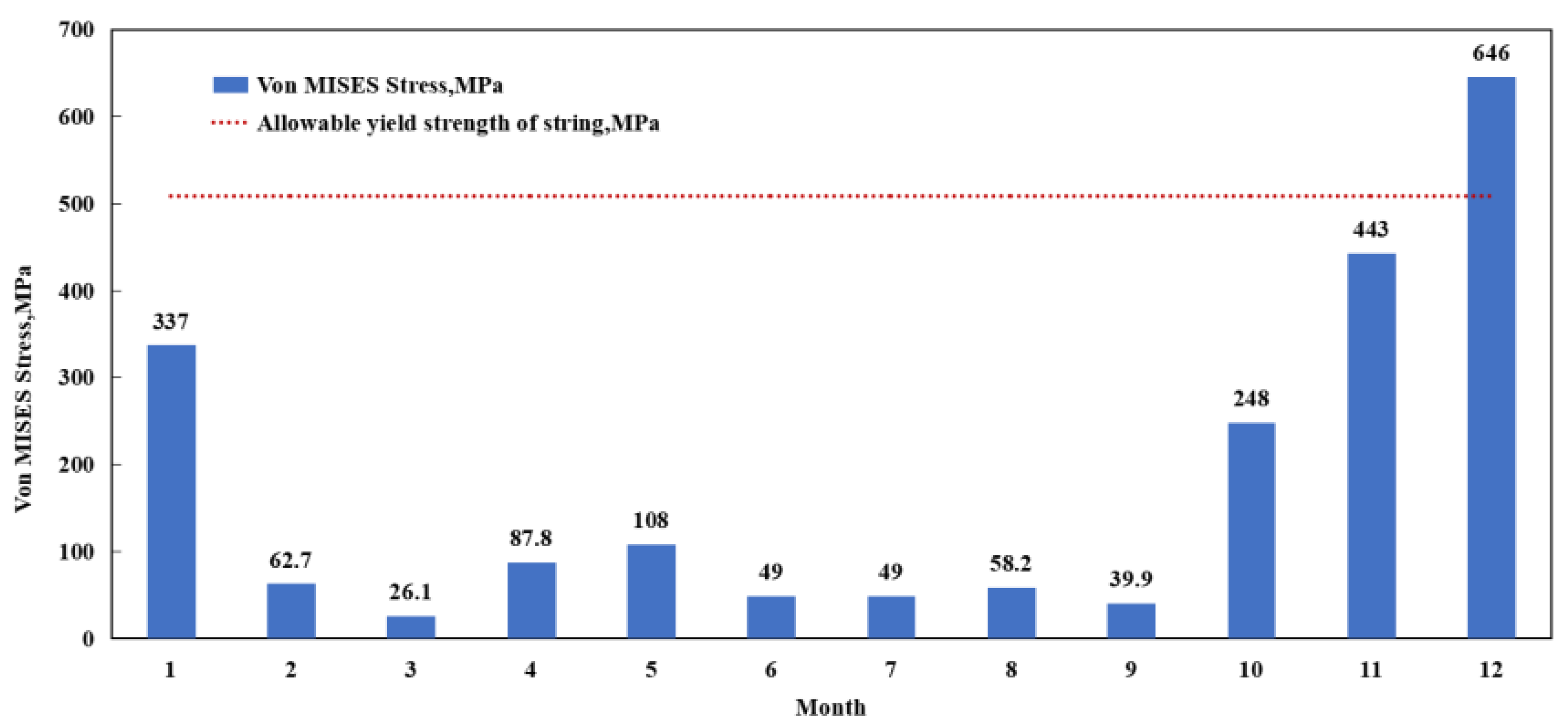
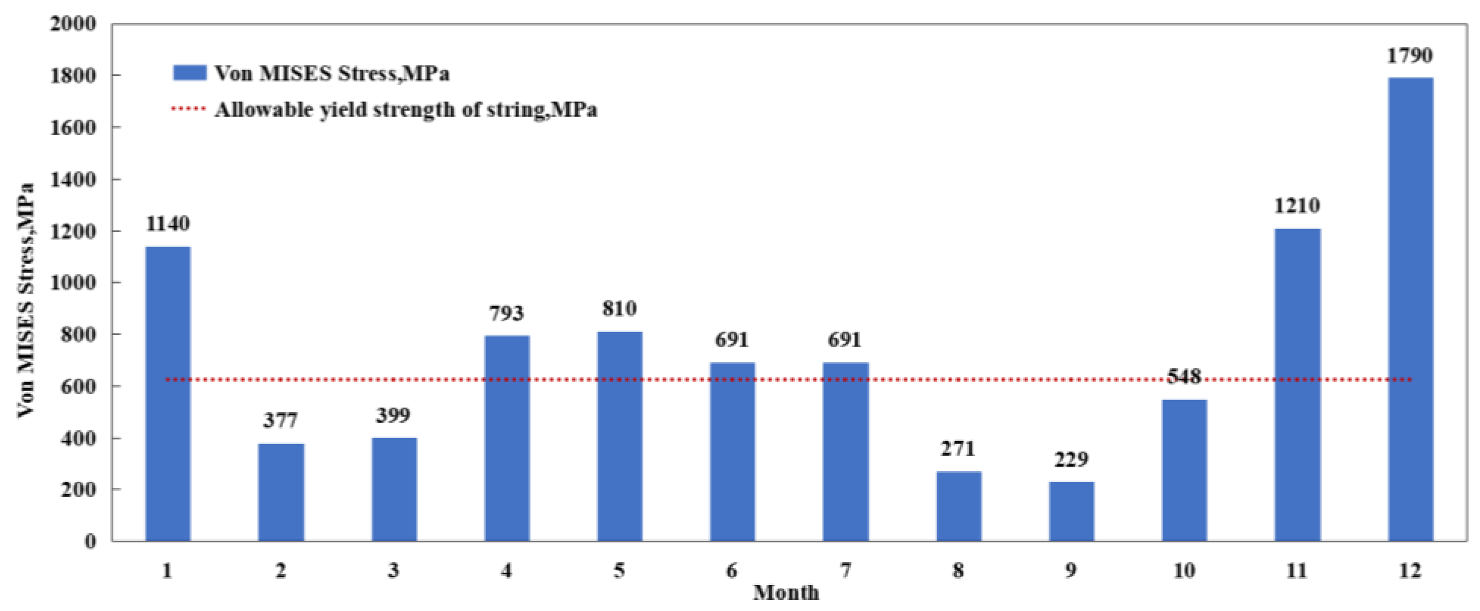
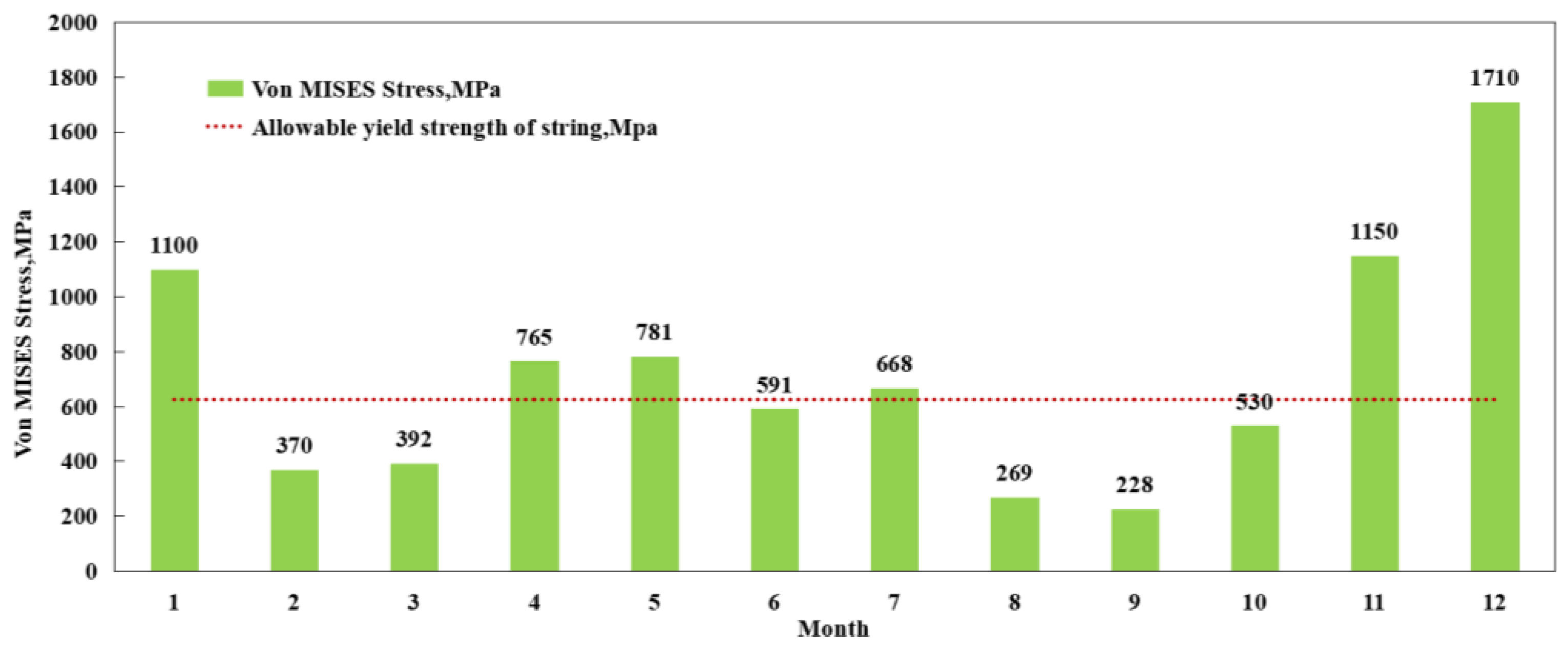
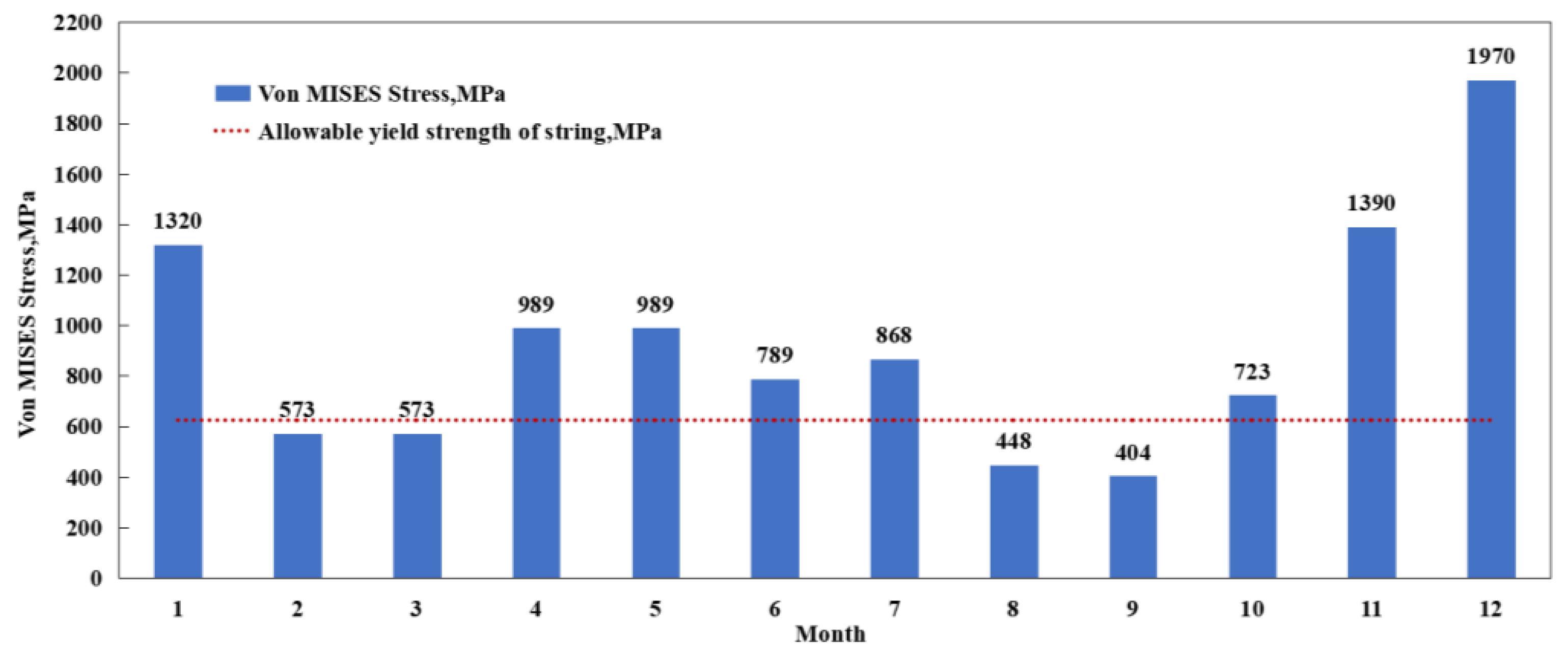
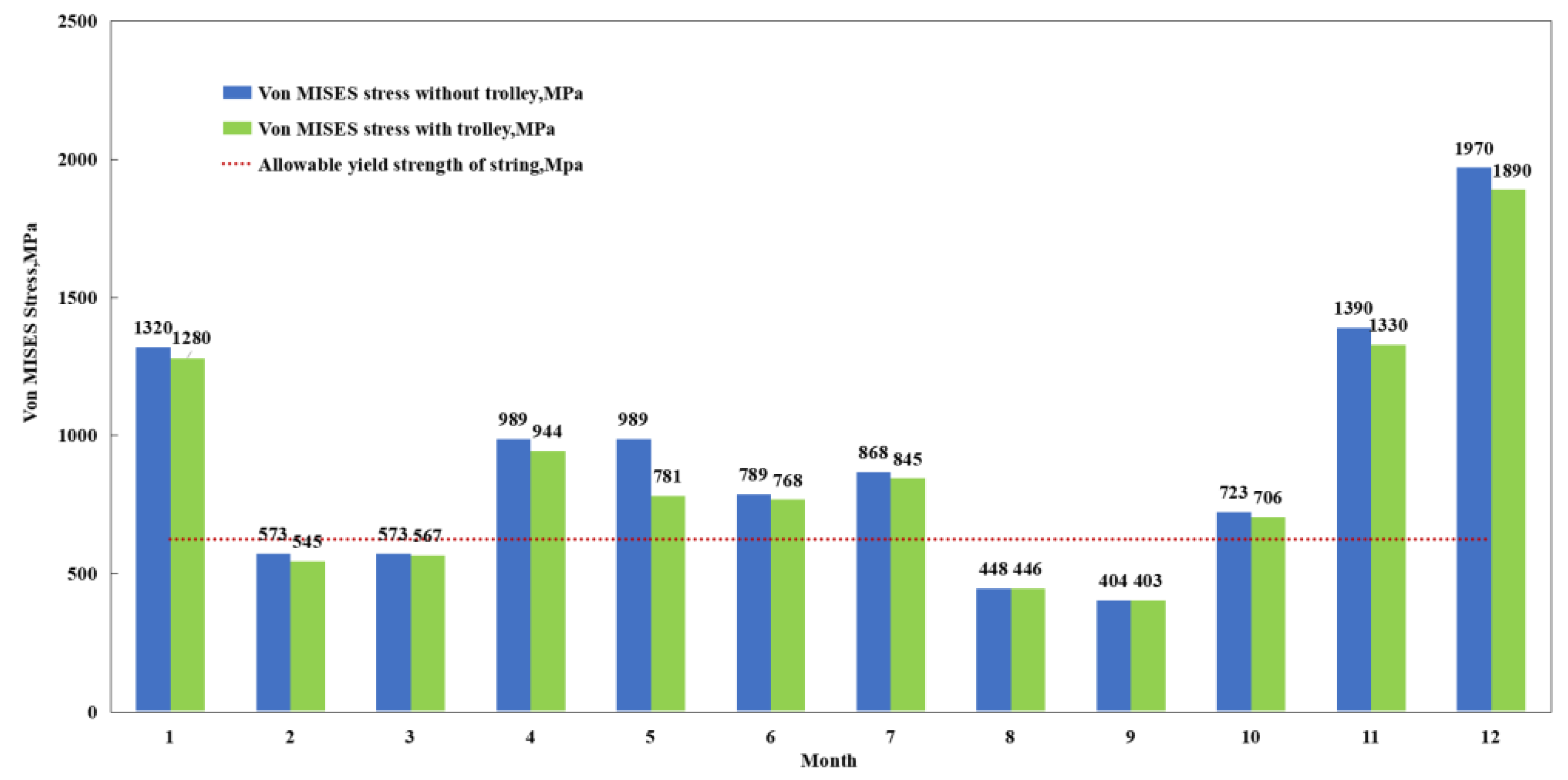
5.3.2. Calculation of Von MISES Stress
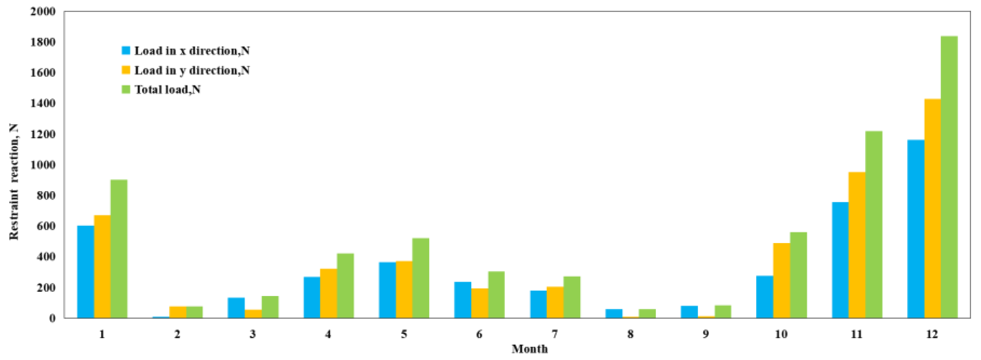
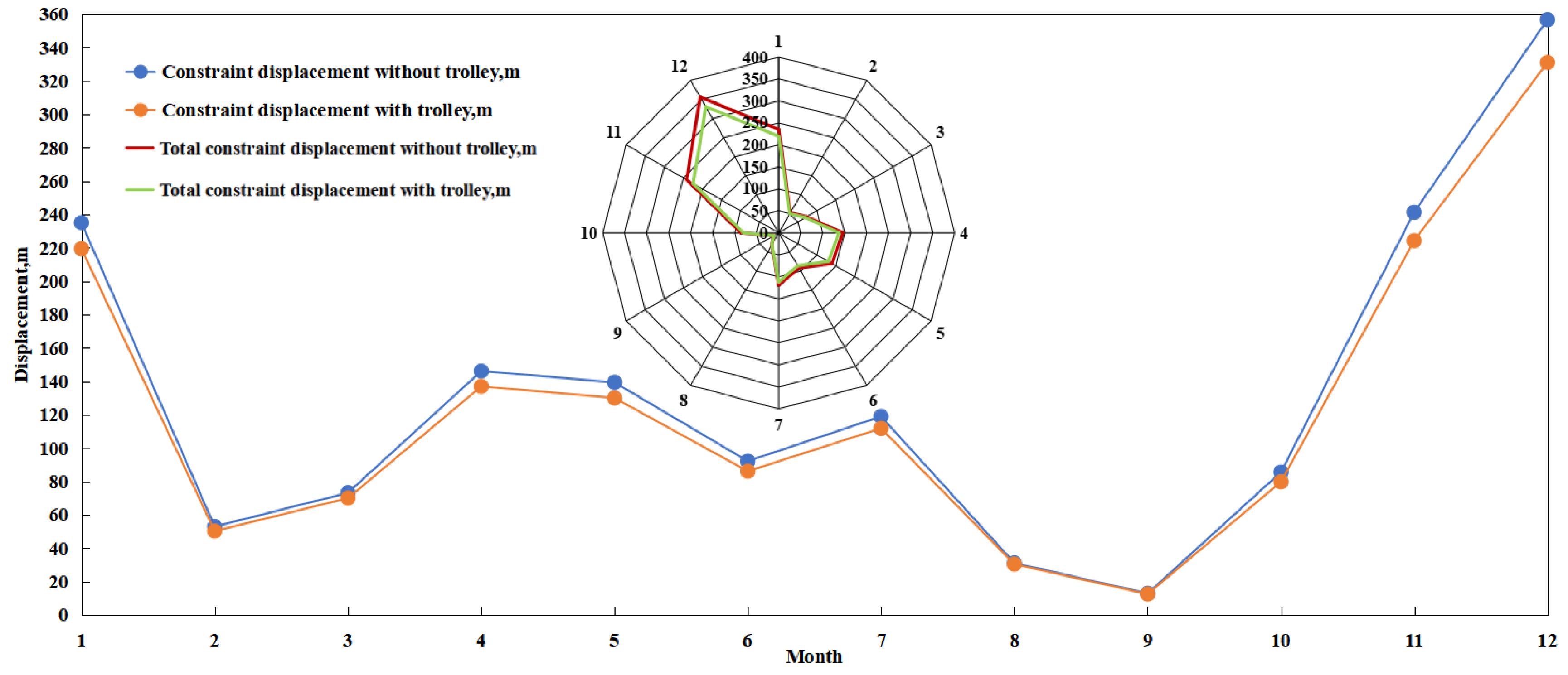
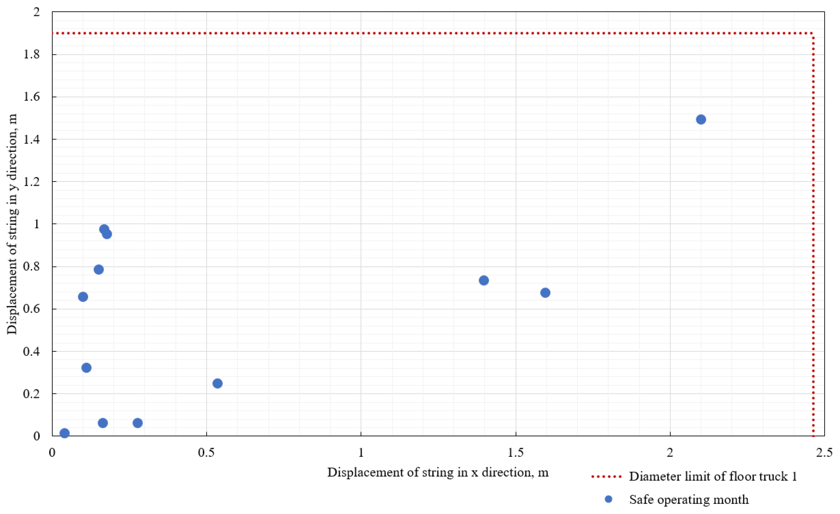
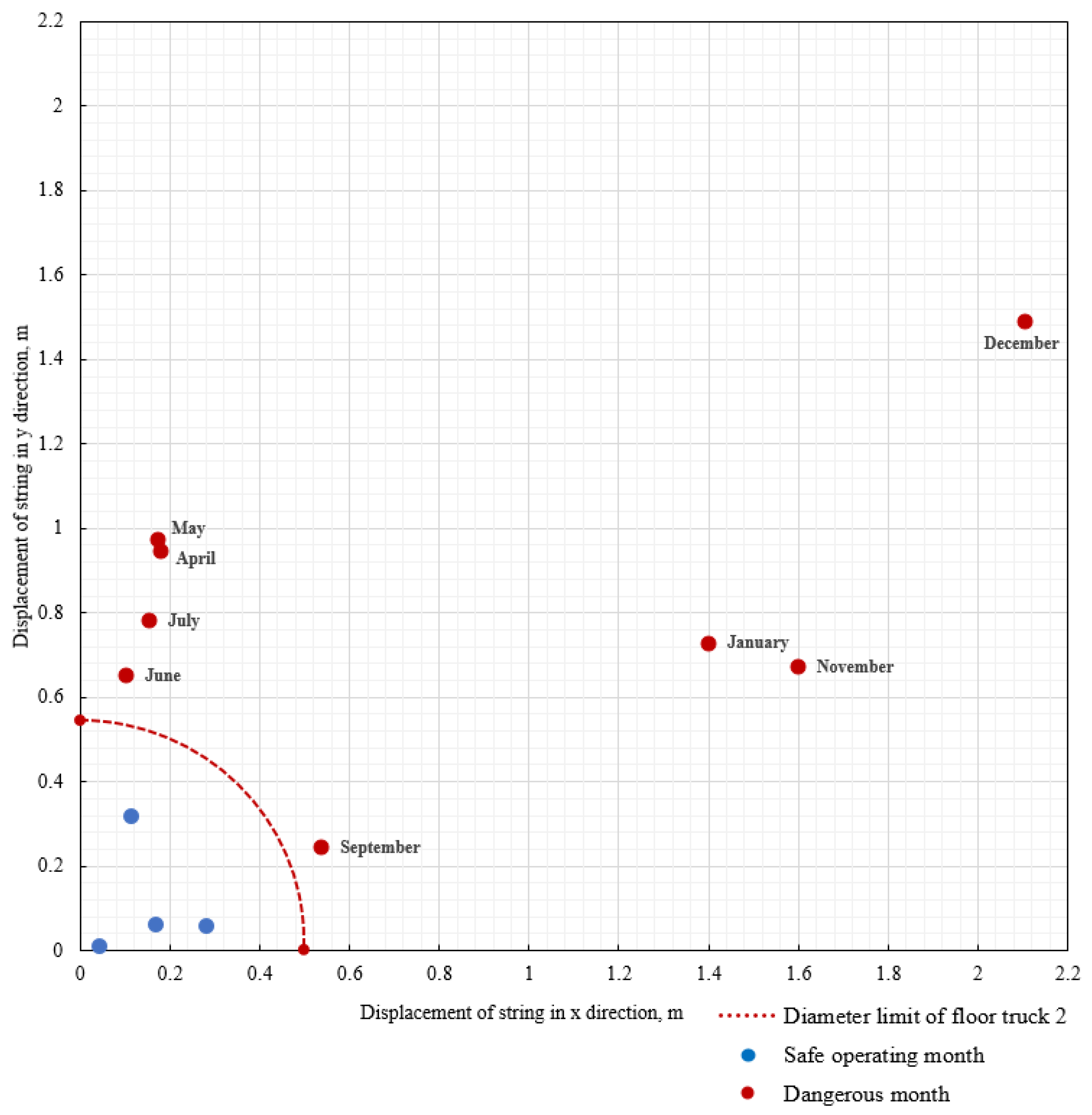
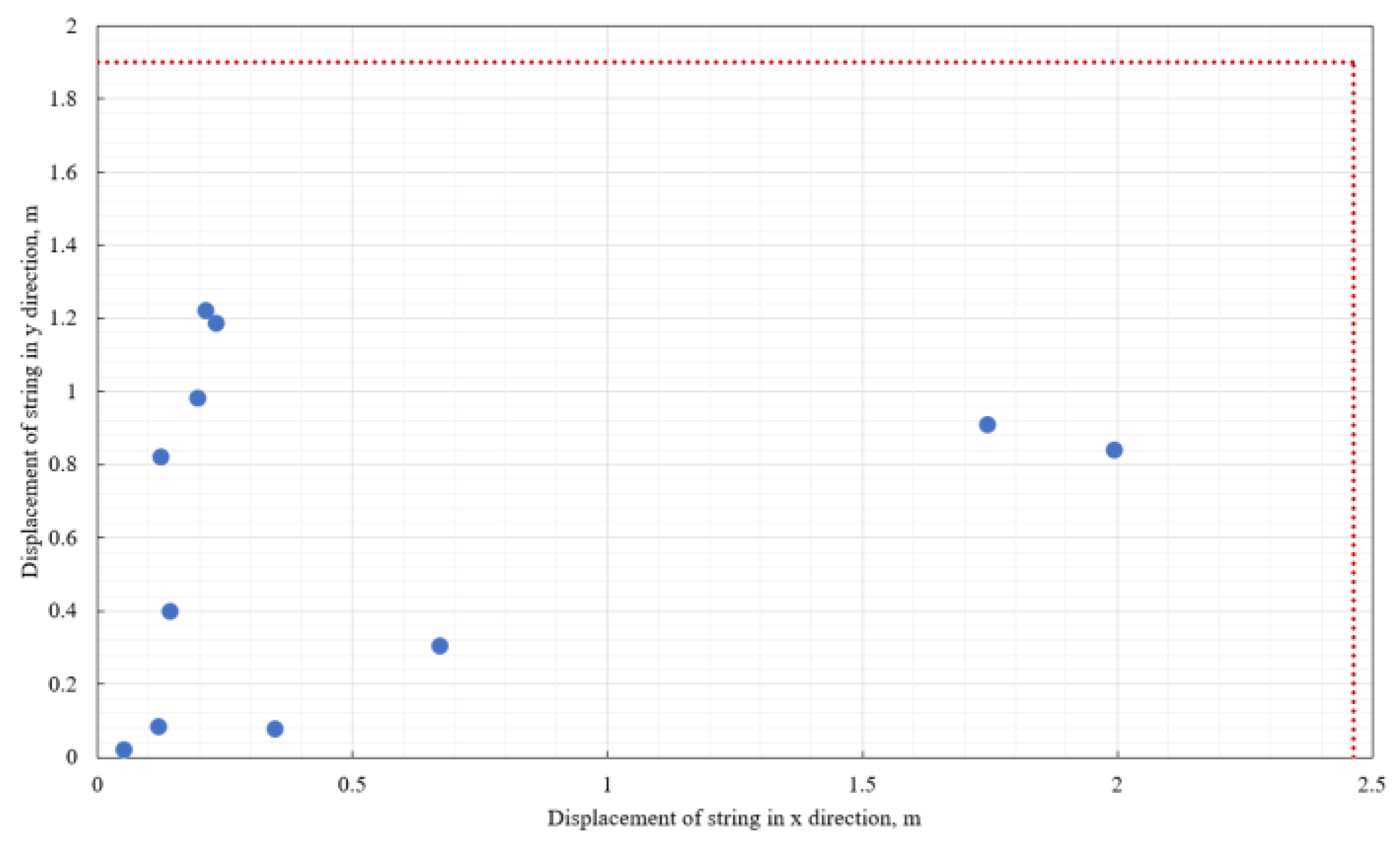
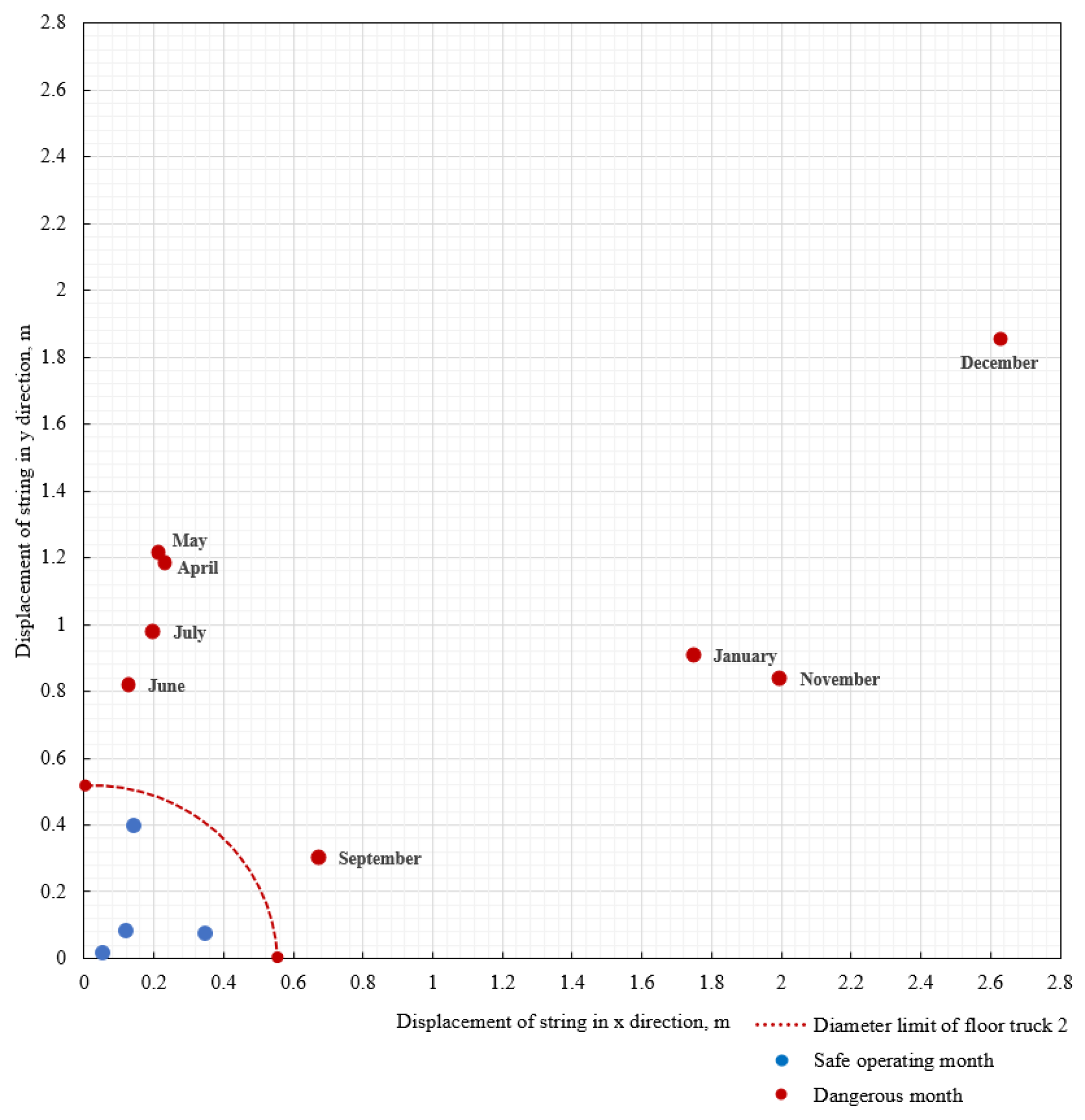
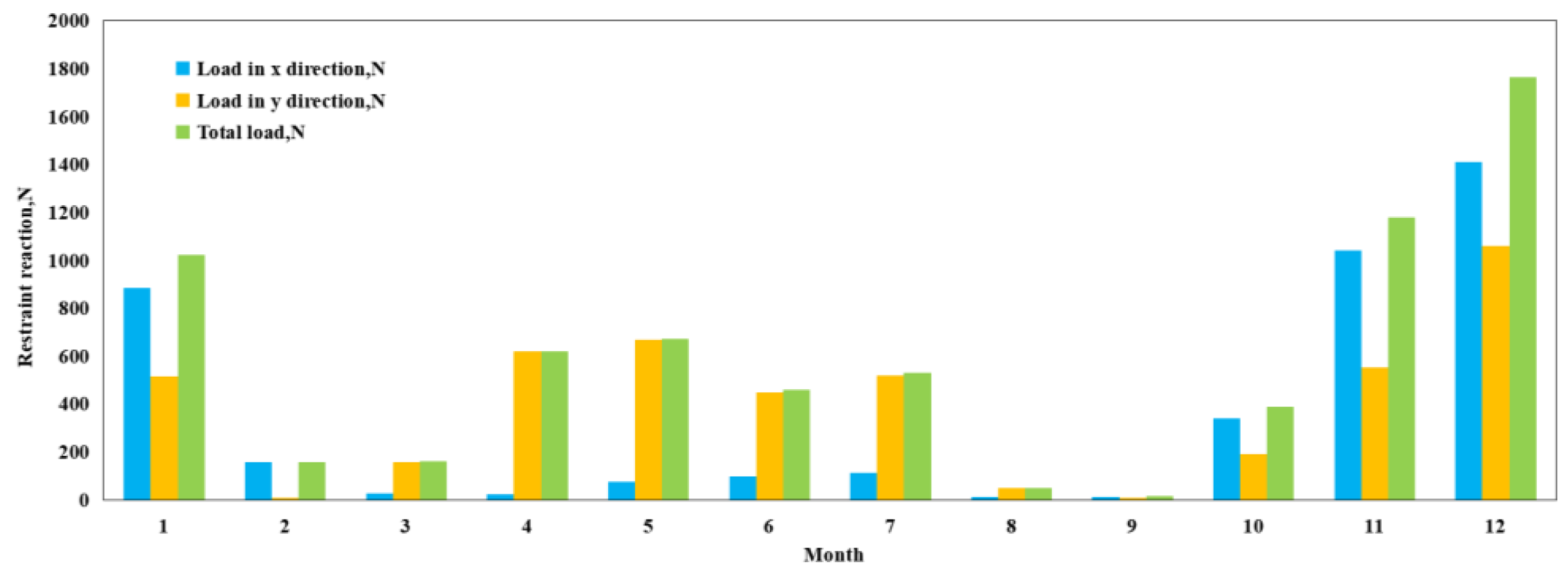
5.3.3. Calculation of BOP Trolley Limiting the Lateral Displacement of the String and Restraining the Reaction Force
5.4. Strength Check of Drill Pipe Carrying Casing into Water Stage
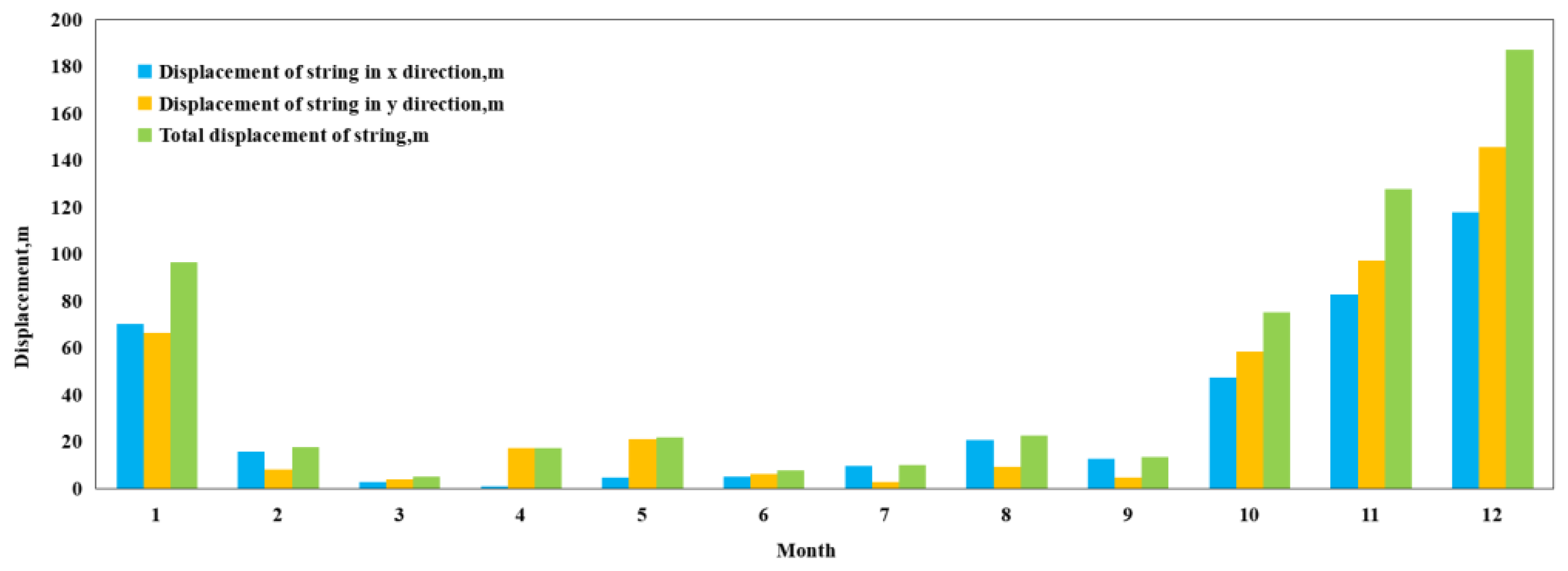
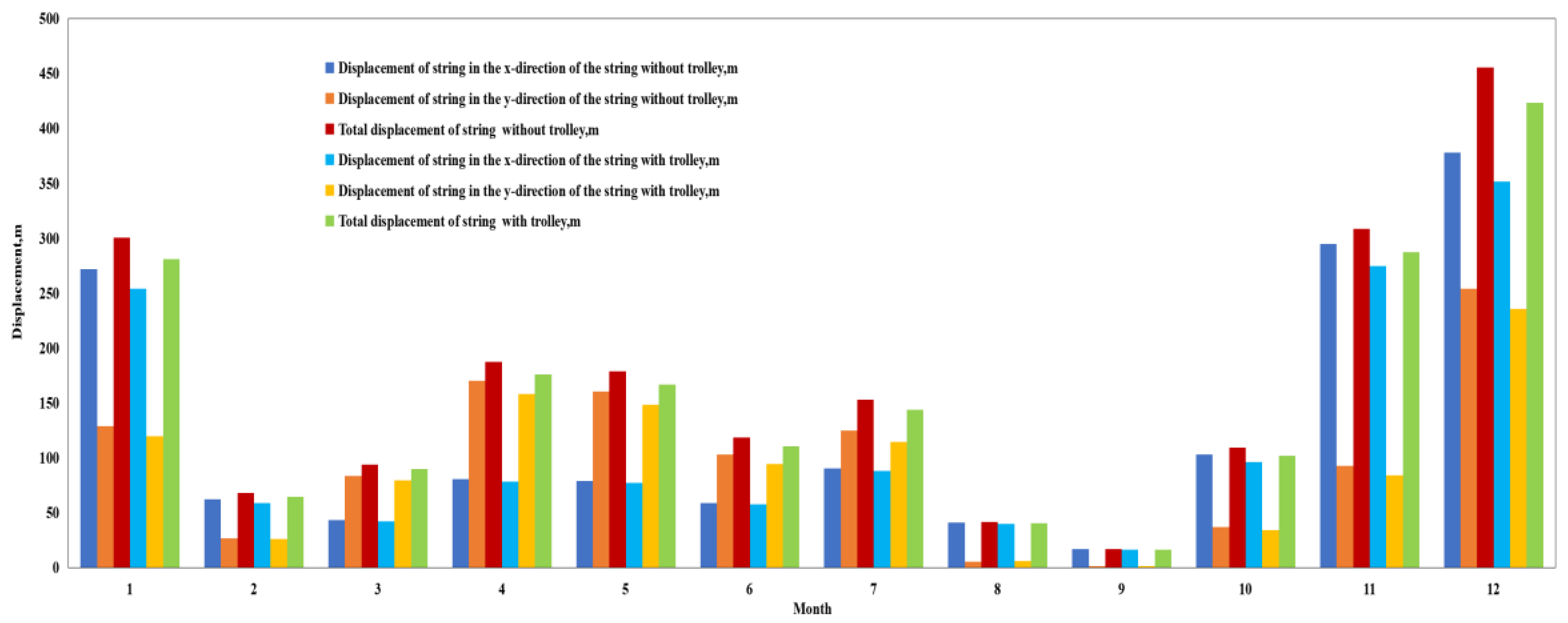
5.4.1. Calculation of Lateral Displacement
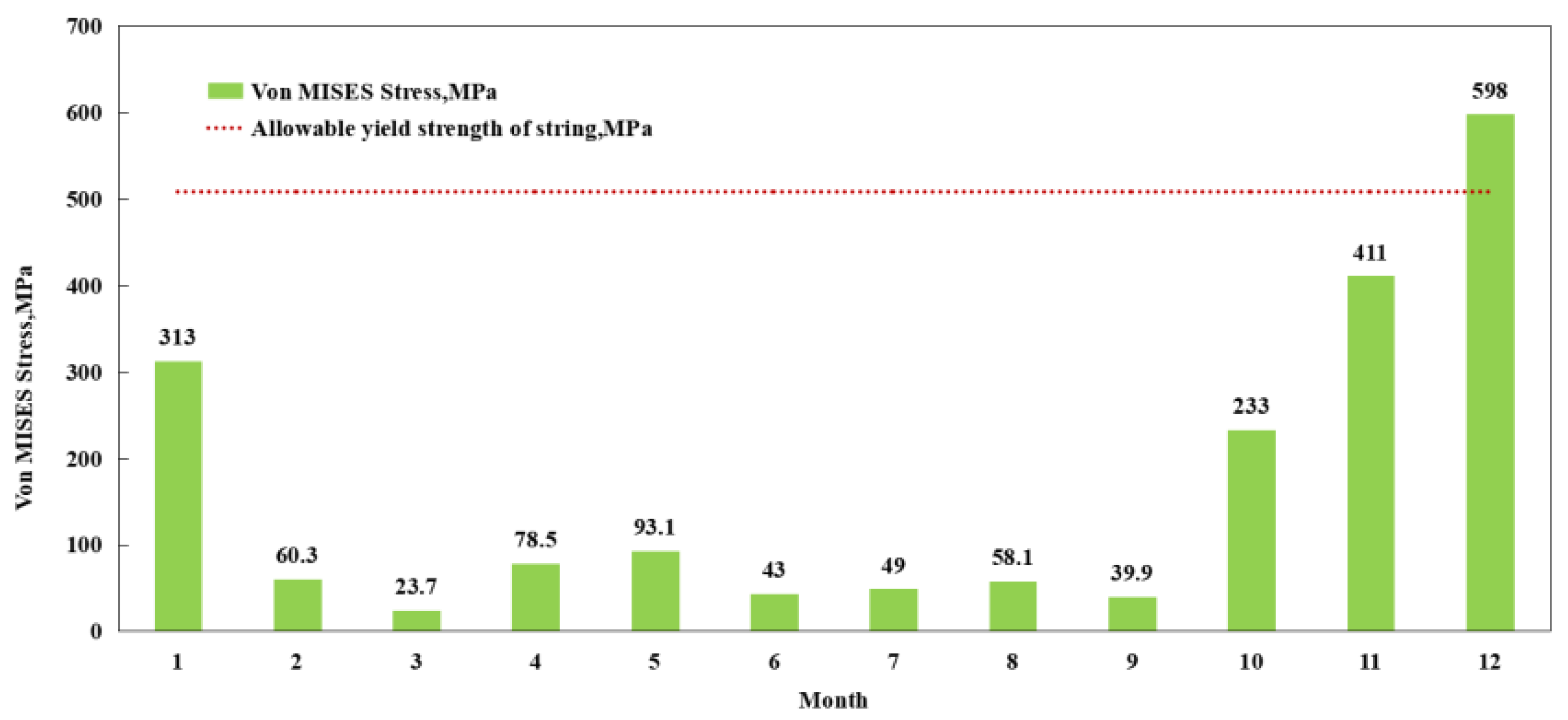
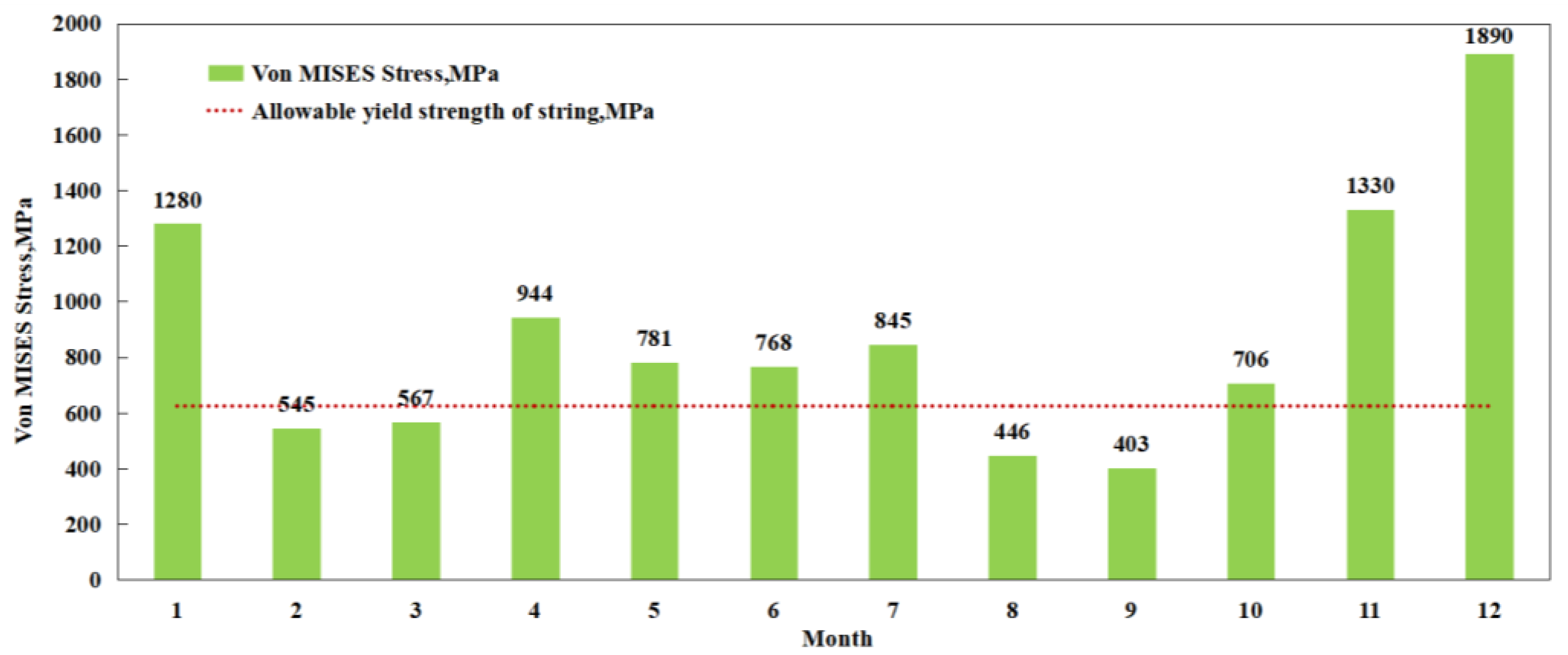
5.4.2. Calculation of Von MISES Stress
5.4.3. Calculation of BOP Trolley Limiting the Lateral Displacement of the String and Restraining the Reaction Force
5.5. Strength Check of Drill Pipe Carrying Casing into Wellhead Stage
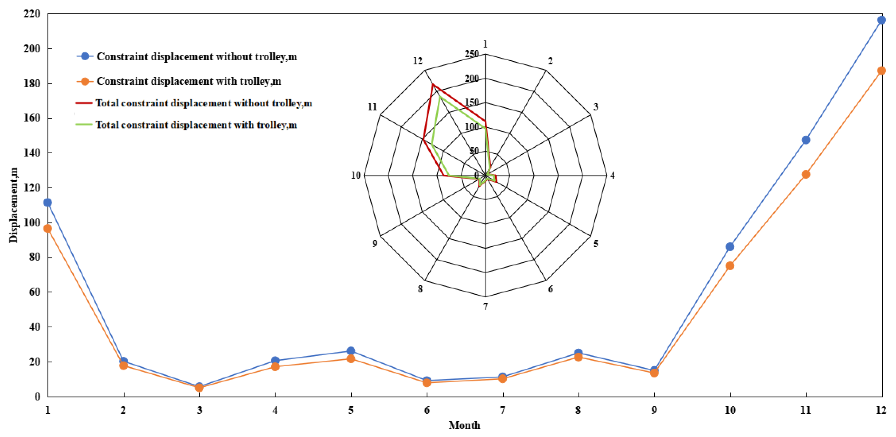
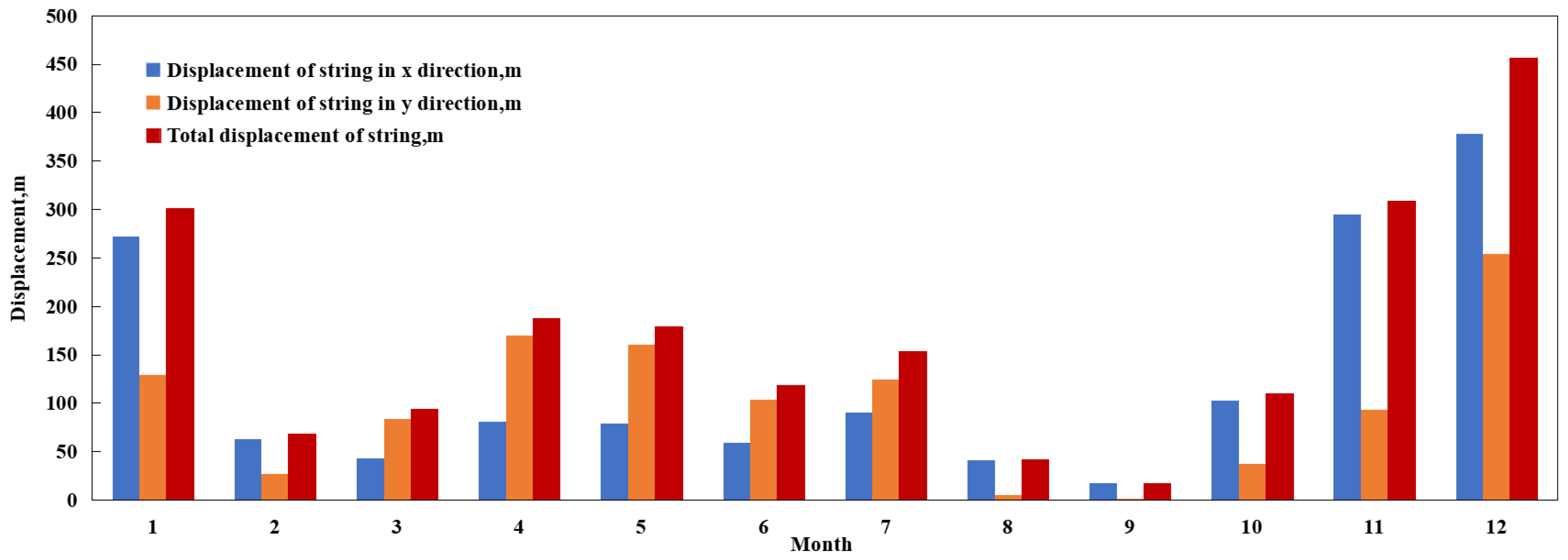
5.5.1. Calculation of Lateral Displacement
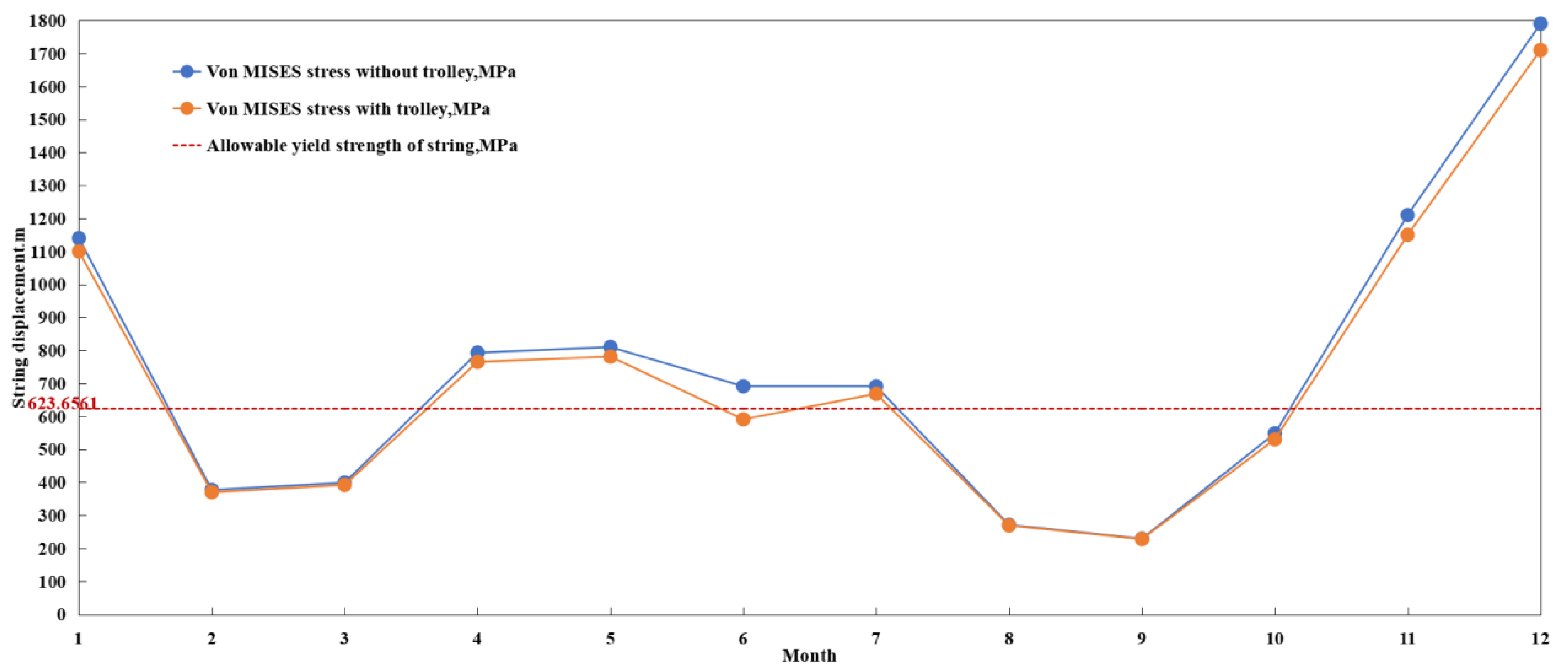
5.5.2. Calculation of Von MISES Stress
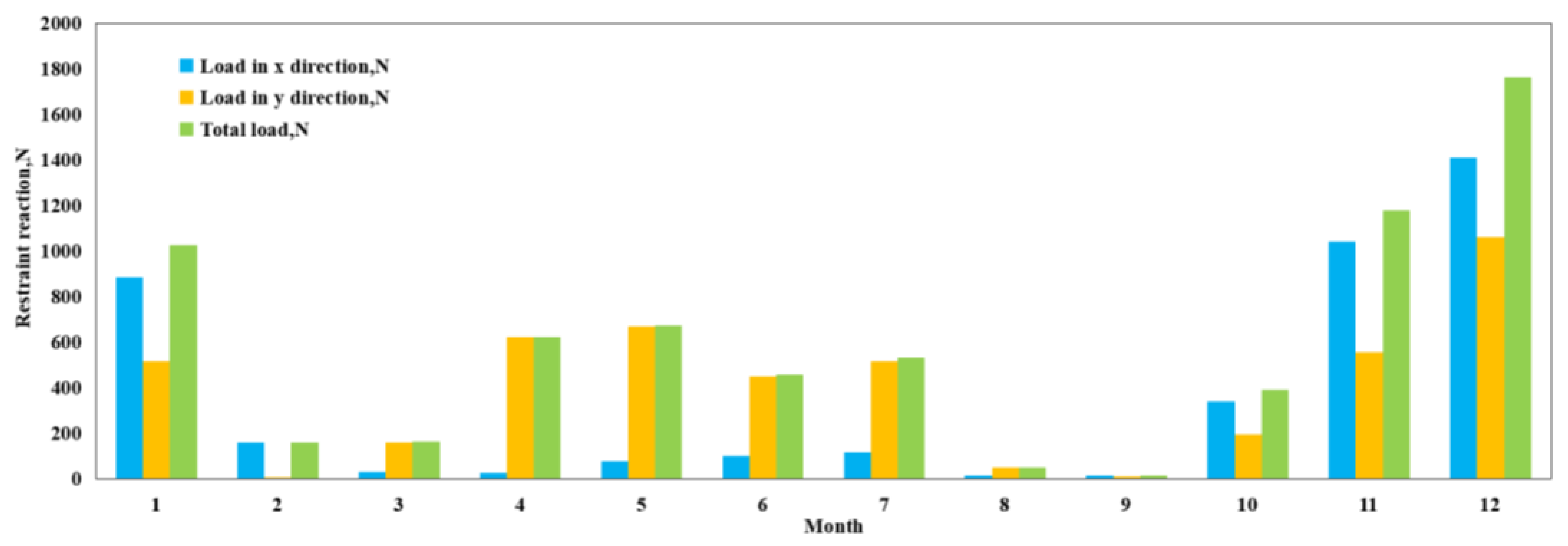
5.5.3. Calculation of BOP Trolley Limiting the Lateral Displacement of the String and Restraining the Reaction Force
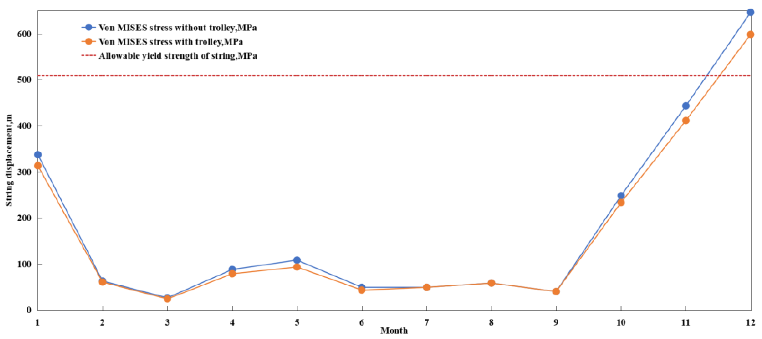
6. Discussion
7. Conclusions
Author Contributions
Funding
Conflicts of Interest
References
- Liu, X.; Shi, Y.; Li, Y.; Liu, Z.; Qiu, N.; Chang, Y.; Chen, G. Mechanical interference properties of two parallel strings in a deepwater dual-derrick drilling system. Ocean Eng. 2023, 269, 113720. [Google Scholar] [CrossRef]
- Yang, J.; Li, L.; Yang, Y.; Zhang, M. Research on stability of deepwater drilling riser system in freestanding mode. Ocean Eng. 2023, 279, 114439. [Google Scholar] [CrossRef]
- Zhang, B.-L.; Cai, Z.; Zhang, W.; Pang, F.-B.; Han, Q.-L.; Zhang, X.-M. Recoil suppression of deepwater drilling riser systems via static output feedback control with memory. Ocean Eng. 2023, 271, 113691. [Google Scholar] [CrossRef]
- Xu, L.; Yin, Z.; Chen, G.; Wang, H.; Chang, Y. Nonlinear static analysis of top tensioned drilling riser in deepwater. China Offshore Oil Gas 2007, 19, 203–207. [Google Scholar]
- Zhu, R.; Zhou, J.; Jiang, S.; Jiang, W. Study on the model of landing string’s slip crushing loads in deep water drilling. China Offshore Oil Gas 2013, 25, 54–58. [Google Scholar]
- Jiao, J.; Wu, Y. Calibration method for landing string in deepwater drilling. Petro Chem. Equip. 2021, 24, 5–8. [Google Scholar]
- Wang, X. Research on Technology and Application of Tubing Hanger Landing String in Deepwater Well Completion. Ocean Eng. Equip. Technol. 2020, 7, 352–355. [Google Scholar]
- Zhang, X.; Sun, Z.; Tong, W.; Zhao, S.; Li, J. Deepwater drilling landing string axial force analysis. Petrochem. Ind. Technol. 2017, 24, 270. [Google Scholar]
- Shan, F.; Wang, J.; Xu, Y.; Zhang, G.; Wen, G.; Li, X. Carbonate ultra-deep horizontal well completion optimization of handing process for landing string. Well Test. 2017, 26, 58–60. [Google Scholar]
- Wang, Y. Development of hydraulic shear pin type completion landing string tool. West-China Explor. Eng. 2021, 33, 48–50. [Google Scholar]
- Yang, Y.; Chen, Q.; Wei, H.; Wang, P.; Tang, T.; Peng, Y. Study and Application of Managed Pressure Technology of Running Casing in Narrow Safety Density Window Formations. Drill. Prod. Technol. 2022, 45, 1–8. [Google Scholar]
- Adams, R.J. Proven landing string design for ultra deepwater application. World Oil 2001, 222, 73–79. [Google Scholar]
- Everage, D.W.; Zheng, N.; Ellis, S.E. Evaluation of Heave-Induced Dynamic Loading on Deepwater Landing Strings. Spe Drill. Complet. 2005, 20, 230–237. [Google Scholar] [CrossRef]
- Bradford, D.W.; Payne, M.L.; Schultz, D.E.; Adams, B.A.; Vandervort, K.D. Defining the Limits of Tubular-Handling Equipment at Extreme Tension Loadings. SPE Drill. Complet. 2009, 24, 72–88. [Google Scholar] [CrossRef]
- Hui, Z.; Gao, D.; Tang, H. Landing string design and strength check in ultra-deepwater condition. J. Nat. Gas Sci. Eng. 2010, 2, 178–182. [Google Scholar] [CrossRef]
- Gao, D.; Hui, Z. Mechanical Analysis of Tubes in Deepwater Drilling Operation Without Riser. Sci. Technol. Rev. 2012, 30, 6. [Google Scholar]
- Jellison, M.J.; Chan, A. Advanced Technologies and Practical Solutions for Challenging Drilling Applications. In IADC/SPE Asia Pacific Drilling Technology Conference; SPE-170566-MS; OnePetro: Calgary, AB, Canada, 2014. [Google Scholar]
- Plessis, G.J.; Verhoef, R.; Ringstad, S.I.; Pangilinan, A.; Liotta, J. Landing String: Breaking the 2.5 Million Pounds Limit. In Iadc/spe Drilling Conference & Exhibition; SPE-178777-MS; OnePetro: Calgary, AB, Canada, 2016. [Google Scholar]
- Simpson, B.; Payne, M.L.; Jellison, M.J.; Adams, B.A. 2,000,000 lb. Landing String Developments: Novel Slipless Technology Extends the Deepwater Operating Envelope. Spe Drill. Complet. 2005, 20, 9–122. [Google Scholar] [CrossRef]
- American Petroleum Institute. Spec 16R. Specification for Marine Drilling Riser Coupling; American Petroleum Institute: Washington, DC, USA, 1997. [Google Scholar]
- Breihan, J.W.; Prideco, G., III; Altermann, J.A.; Jellison, M.J. Landing Tubulars Design, Manufacture, Inspection and Use Issues. In SPE/IADC Drilling Conference; SPE-67723-MS; OnePetro: Calgary, AB, Canada, 2001. [Google Scholar]
- American Petroleum Institute. 16Q. Recommended Practice for DESIGN selection Operation and Maintenance of Marine Drilling Riser System; American Petroleum Institute: Washington, DC, USA, 2001. [Google Scholar]
- Liu, K.; Zhu, J.; Zhang, S.; Chen, G.; Zhang, W. Mechanical property and influence factor of deep water landing strings in guided running. China Offshore Oil Gas 2018, 30, 137–143. [Google Scholar]
- ISO 13625; Petrolrum and Natural Gas Industries-Drilling and Proudction Equipment-Maring Drilling Riser Coupling. International Organization for Standardization: Geneva, Switzerland, 2002.
- Wang, Y.; Gao, D.; Fang, J. Static analysis of deep-water marine riser subjected to both axial and lateral forces in its installation. J. Nat. Gas Sci. Eng. 2014, 19, 84–90. [Google Scholar] [CrossRef]
- He, L.A.; Dg, A.; Ws, A. A new mathematical model for evaluating the safe margin of deepwater landing operation—ScienceDirect. Appl. Ocean Res. 2020, 104, 102375. [Google Scholar]
- Zhang, H.; Gao, D.; Tang, H. Choice of Landing String under Ultra-Deepwater Drilling Condition. In International Oil & Gas Conference & Exhibition in China; SPE-131168-MS; OnePetro: Calgary, AB, Canada, 2010. [Google Scholar]
- Jia, X.; Fang, C. Dynamic Response of Offshore Drilling Risers. China Pet. Mach. 1995, 23, 6. [Google Scholar]
- Liu, J.; Zhao, H.; Yang, S.X.; Liu, Q.; Wang, G. Nonlinear Dynamic Characteristic Analysis of a Landing String in Deepwater Riserless Drilling. Shock Vib. 2018, 2018, 1–17. [Google Scholar] [CrossRef]
- GB/T 19830-2011; Petroleum and Natural Gas Industries-Steel Pipes for Use as Casing or Tubing for Wells. International Organization for Standardization: Geneva, Switzerland, 2011.
- GB/T 24956-2010; Recommended Practice for Petroleum and Natural Gas Industries—Drill Stem Design and Operating Limits. International Organization for Standardization: Geneva, Switzerland, 2010.
- Zhu, H.; Li, D.; Wei, C.; Li, Q. Research on LS17-2 deep water gas field development engineering scenario in South China Sea. China Offshore Oil Gas 2018, 30, 170–177. [Google Scholar]
- Qin, K.; Di, Q.; Zhou, X. Nonlinear dynamic characteristics of the drill-string for deep-water and ultra-deep water drilling. J. Pet. Sci. Eng. 2021, 209, 109905. [Google Scholar] [CrossRef]
- Tang, Y.; Wu, J.; Luo, Y.; Li, W. Development status of landing string control system and research difficulties for its localization. China Offshore Oil Gas 2022, 34, 138–145. [Google Scholar]
- Guan, Z.; Li, J.; Han, C.; Zhang, B.; Zhao, X.; Teng, X.; Sun, B. Loads calculation and strength analysis of landing string during deepwater drilling. J. China Univ. Pet. (Ed. Nat. Sci.) 2018, 42, 71–78. [Google Scholar]
- Zhou, C.; Fu, Y.; Zhu, R. Design Method and Development Trend of Landing Strings in Deepwater Drilling. Pet. Drill. Tech. 2014, 42, 1–7. [Google Scholar]
- American Petroleum Institute. 2RD: Design of Risers for Floating Production Systems and Tension-Leg Platforms; American Petroleum Institute: Washington, DC, USA, 1998. [Google Scholar]
- American Petroleum Institute. Spec 16F: Specification for Marine Drilling Riser Equipment; American Petroleum Institute: Washington, DC, USA, 2004. [Google Scholar]
- Martirosyan, A.V.; Kukharova, T.V.; Fedorov, M.S. In Research of the Hydrogeological Objects’ Connection Peculiarities, 2021. In Proceedings of the IV International Conference on Control in Technical Systems (CTS), Saint Petersburg, Russia, 21–23 September 2021. [Google Scholar]


| Parameter | 244.48 mm Casing (9-5/8in) | 149.2 mm Drill Pipe (5-7/8in) |
|---|---|---|
| Outer Diameter, mm | 244.48 | 149.2 |
| Inside Diameter, mm | 220.5 | 118.7 |
| Wall Thickness, mm | 11.99 | 15.25 |
| Cross-sectional Area, mm2 | 8757 | 6417 |
| Single Length, m | 12–13 | 14.09 |
| Weight Per Meter, N/m | 685.51 | 697.27 |
| Tensile Strength, kN | 8450 | 5974 |
| Torsional Strength, kN·m | / | 186 |
| Anti-extrusion Strength, MPa | 56 | 192 |
| Internal Compressive Strength, MPa | 63.2 | 181 |
| Yield Strength, MPa | 758.42 | 930.83 |
| Connector Specifications | BC | 5-1/2 FH (7.625 × 3.375) |
| Joint Tensile Strength, kN | 8192 | 7558 |
| Joint Torsional Strength, kN·m | / | 104 |
| Steel Grade | P110 | S-135 |
| Elastic Modulus, GPa | 210 | 210 |
| Poisson Ratio | 0.3 | 0.3 |
| Month | Water Depth, m | Surface | 200 | 400 | 800 | Bottom | Wind Speed, m/s | Wind Direction, ° | Significant Wave Height, m | Cycle, s | Wave Attack Angle, Deg |
|---|---|---|---|---|---|---|---|---|---|---|---|
| 1 | Flow Velocity, m/s | 0.254 | 0.156 | 0.076 | 0.035 | 0.008 | 7.4 | 54.9 | 1.7 | 5.4 | 58.3 |
| Flow Direction, ° | 217.2 | 228.2 | 217.1 | 191.5 | 325.3 | ||||||
| 2 | Flow Velocity, m/s | 0.091 | 0.068 | 0.035 | 0.03 | 0.006 | 5.4 | 71.8 | 1.6 | 5.3 | 67 |
| Flow Direction, ° | 201 | 220.3 | 186.5 | 139.1 | 88.1 | ||||||
| 3 | Flow Velocity, m/s | 0.081 | 0.017 | 0.034 | 0.042 | 0.007 | 4.3 | 106.1 | 1.4 | 5 | 85.3 |
| Flow Direction, ° | 73.5 | 120.1 | 142.3 | 138.4 | 81.2 | ||||||
| 4 | Flow Velocity, m/s | 0.201 | 0.057 | 0.029 | 0.036 | 0.005 | 4.4 | 135.1 | 1.3 | 4.7 | 99.4 |
| Flow Direction, ° | 60.4 | 73.9 | 149.8 | 154.3 | 316.9 | ||||||
| 5 | Flow Velocity, m/s | 0.221 | 0.069 | 0.027 | 0.025 | 0.01 | 3.9 | 156.6 | 1.1 | 4.5 | 115.7 |
| Flow Direction, ° | 50 | 66 | 146.4 | 176.8 | 339.1 | ||||||
| 6 | Flow Velocity, m/s | 0.189 | 0.02 | 0.045 | 0.021 | 0.014 | 4.6 | 175.7 | 1 | 4.2 | 149 |
| Flow Direction, ° | 35.9 | 120.1 | 196.2 | 197.5 | 328.8 | ||||||
| 7 | Flow Velocity, m/s | 0.2 | 0.019 | 0.054 | 0.036 | 0.009 | 4.6 | 180.1 | 1 | 4.1 | 160 |
| Flow Direction, ° | 32.3 | 184.5 | 200.2 | 197.1 | 332.2 | ||||||
| 8 | Flow Velocity, m/s | 0.055 | 0.059 | 0.067 | 0.038 | 0.016 | 2.9 | 192.2 | 1 | 4.4 | 155.9 |
| Flow Direction, ° | 26.3 | 211.2 | 207.4 | 198.4 | 330.6 | ||||||
| 9 | Flow Velocity, m/s | 0.017 | 0.054 | 0.044 | 0.025 | 0.01 | 14 | 125.5 | 1.1 | 4.5 | 120.3 |
| Flow Direction, ° | 63.8 | 210.6 | 197.6 | 172.7 | 337.8 | ||||||
| 10 | Flow Velocity, m/s | 0.16 | 0.154 | 0.056 | 0.018 | 0.012 | 5.3 | 58.9 | 1.6 | 5.2 | 68.7 |
| Flow Direction, ° | 222.6 | 235.5 | 225.2 | 173.6 | 350.8 | ||||||
| 11 | Flow Velocity, m/s | 0.282 | 0.187 | 0.079 | 0.024 | 0.01 | 8.5 | 47.2 | 2 | 5.7 | 60 |
| Flow Direction, ° | 218.8 | 233.6 | 225.3 | 178 | 15.7 | ||||||
| 12 | Flow Velocity, m/s | 0.345 | 0.225 | 0.097 | 0.025 | 0.013 | 9.4 | 45.4 | 2.2 | 5.9 | 59.4 |
| Flow Direction, ° | 221.1 | 233.4 | 231 | 204.5 | 351.6 |
| Return Period, Year | Wind Speed, m/s | Significant Wave Height, m | Spectral Peak Period, s | Surface Velocity, m/s | Bottom Flow Rate, m/s |
|---|---|---|---|---|---|
| 200 | 22.1 | 7.0 | 7.2 | 1.89 | 0.27 |
| 100 | 21.4 | 6.6 | 7.1 | 1.75 | 0.25 |
| 50 | 20.7 | 6.2 | 7.0 | 1.61 | 0.24 |
| 40 | 20.5 | 6.1 | 6.9 | 1.56 | 0.23 |
| 25 | 19.9 | 5.8 | 6.8 | 1.47 | 0.22 |
| 20 | 19.7 | 5.7 | 6.8 | 1.42 | 0.22 |
| 10 | 18.9 | 5.2 | 6.6 | 1.28 | 0.20 |
| Return Period, Year | Wind Speed, m/s | Significant Wave Height, m | Spectral Peak Period, s | Surface Velocity, m/s | Bottom Flow Rate, m/s |
|---|---|---|---|---|---|
| 200 | 45.6 | 20.1 | 16.4 | 2.27 | 0.33 |
| 100 | 40.8 | 16.8 | 15.4 | 2.17 | 0.32 |
| 50 | 36.5 | 13.9 | 14.5 | 2.06 | 0.30 |
| 40 | 35.2 | 13.1 | 14.2 | 2.03 | 0.29 |
| 25 | 32.6 | 11.4 | 13.6 | 1.96 | 0.28 |
| 20 | 31.4 | 10.7 | 13.3 | 1.92 | 0.28 |
| 10 | 28.0 | 8.6 | 12.4 | 1.82 | 0.26 |
| Return Period, Year | Surface Velocity, m/s | Wind Speed, m/s | Wave Height, m | Cycle, s | |
|---|---|---|---|---|---|
| 1 | Min | 0.35 | 9.4 | 2.2 | 5.9 |
| Max | 0.70 | ||||
| 5 | Min | 0.56 | 20.0 | 5.4 | 9.2 |
| Max | 1.40 | ||||
| 10 | Min | 0.61 | 28.0 | 8.6 | 12.4 |
| Max | 1.49 | ||||
| 25 | Min | 0.67 | 32.6 | 11.4 | 13.6 |
| Max | 1.59 | ||||
| 40 | Statistics | 2.03 | 35.2 | 13.1 | 14.2 |
| 50 | Statistics | 2.06 | 36.5 | 13.9 | 14.5 |
| 100 | Statistics | 2.17 | 40.8 | 16.8 | 15.4 |
| 200 | Statistics | 2.27 | 45.6 | 20.1 | 16.4 |
| Water Layer Depth, m | Amplitude 1, m | Amplitude 2, m | Amplitude 3, m | Amplitude 4, m | Amplitude 5, m | Max Wave Speed, m/s |
|---|---|---|---|---|---|---|
| 60/1600 | 20 | 40 | 60 | 80 | 100 | 1.6 |
| Name | Sign | Value |
|---|---|---|
| Drag Coefficient | 1.2 (0–150 m below sea level) | |
| 0.7 (150 m below sea level to the seabed) | ||
| Lateral Drag Coefficient | 0.02 | |
| Coefficient Of Inertia | 2.0 |
| String Combination | Ultimate Tensile Load, kN | Tension Allowance Method, kN | Safety Factor Method, kN | Allowable Tensile Load, kN |
|---|---|---|---|---|
| 1200 m 5-7/8in drill pipe and 400 m 9-5/8in casing | 965.40 | 1465.40 | 1905.02 | 5376.6 |
| 1600 m 5-7/8in drill pipe and 400 m 9-5/8in casing | 1207.77 | 1707.77 | 2220.10 | 5376.6 |
| Results of Restraint Reaction Force of Righting Mechanism under Extreme Working Conditions (String Combination: 400 m 9-5/8in Casing, Safety Factor: 1.2) | ||||||||||||
|---|---|---|---|---|---|---|---|---|---|---|---|---|
| Return Period, year | 1 | 5 | 10 | 25 | 40 | 50 | 100 | 200 | ||||
| Surface Velocity m/s | Min | Max | Min | Max | Min | Max | Min | Max | Statistic | Statistic | Statistic | Statistic |
| 0.35 | 0.7 | 0.56 | 1.4 | 0.61 | 1.49 | 0.67 | 1.59 | 2.03 | 2.06 | 2.17 | 2.27 | |
| Wind Speed, m/s | 9.4 | 20 | 28 | 32.6 | 35.2 | 36.5 | 40.8 | 45.6 | ||||
| Wave Height, m | 2.2 | 5.4 | 8.6 | 11.4 | 13.1 | 13.9 | 16.8 | 20.1 | ||||
| Cycle, s | 5.9 | 9.2 | 12.4 | 13.6 | 14.2 | 14.5 | 15.4 | 16.4 | ||||
| Full Drill Stem Stage Simulation to Solve Constrained Reaction Forces Fx, kN | 4.451 | 17.407 | 11.32 | 69.363 | 13.383 | 78.532 | 16.09 | 89.39 | 145.54 | 149.87 | 166.27 | 181.93 |
| Full Drill Stem Stage Simulation to Solve Constrained Reaction Forces Fy, kN | 0 | 0 | 0 | 0 | 0 | 0 | 0 | 0 | 0 | 0 | 0 | 0 |
| Full Drill Stem Stage Simulation to Solve Constrained Reaction Forces Fz, kN | 93.942 | 93.942 | 93.942 | 93.942 | 93.942 | 93.942 | 93.942 | 93.942 | 93.942 | 93.942 | 93.942 | 93.942 |
| Full Drill Stem Stage Simulation to Solve Bending Moment, kN·m | 922.68 | 3689.6 | 2361.8 | 14,757 | 2802.3 | 16,716 | 3380.5 | 19,035 | 31,027 | 31,951 | 35,454 | 38,797 |
| Combined with Safety Factor Simulation to Solve the Support Force kN | 5.3412 | 20.8884 | 13.584 | 83.2356 | 16.0596 | 94.2384 | 19.308 | 107.268 | 174.648 | 179.844 | 199.524 | 218.316 |
| Combined with Safety Factor Simulation to Solve Bending Moment, kN·m | 1107.216 | 4427.52 | 2834.16 | 17,708.4 | 3362.76 | 20059.2 | 4056.6 | 22,842 | 37,232.4 | 38,341.2 | 42,544.8 | 46,556.4 |
| Month | Mechanical Simulation Calculation Results of Drill Pipe Carrying Casing into Wellhead | Mechanical Simulation Calculation Results of Drill Pipe Carrying Casing about to Enter Wellhead | ||||||
|---|---|---|---|---|---|---|---|---|
| X-Displacement-Max, m | Y-Displacement-Max, m | Sum-Displacement-Max, m | Von MISES-Max, MPa | X-Displacement-Max, m | Y-Displacement-Max, m | Sum-Displacement-Max, m | Von MISES-Max, MPa | |
| 1 | 211.772 | 102.065 | 235.083 | 1140 | 289.868 | 160.5 | 331.336 | 2030 |
| 2 | 48.7292 | 21.0568 | 52.9767 | 377 | 79.244 | 55.6839 | 96.8519 | 534 |
| 3 | 33.2295 | 65.2673 | 73.2228 | 399 | 70.8989 | 136.942 | 154.206 | 689 |
| 4 | 61.3072 | 133.118 | 146.174 | 793 | 115.613 | 152.259 | 146.174 | 1230 |
| 5 | 612647 | 125.558 | 139.386 | 810 | 95.6712 | 133.69 | 164.396 | 1220 |
| 6 | 45.891 | 80.3666 | 92.1734 | 691 | 67.3231 | 70.2032 | 97.2671 | 826 |
| 7 | 68.9892 | 97.9518 | 118.946 | 691 | 115.323 | 80.3086 | 140.531 | 963 |
| 8 | 31.1511 | 4.08785 | 31.1937 | 271 | 50.7588 | 58.2531 | 77.265 | 324 |
| 9 | 12.8537 | 143923 | 12.8761 | 229 | 23.6349 | 20.1292 | 31.045 | 227 |
| 10 | 80.1755 | 30.0721 | 85.6296 | 548 | 102.09 | 50.9934 | 114.117 | 818 |
| 11 | 230.171 | 73.0539 | 241.39 | 1210 | 297.791 | 64.6474 | 304.728 | 2060 |
| 12 | 294.904 | 200.69 | 356.712 | 1790 | 370.201 | 276.955 | 462.334 | 3160 |
| Results of Restraint Reaction Force of Righting Mechanism under Extreme Working Conditions (String Combination:1200 m 5-7/8in Drill Pipe + 400 m 9-5/8in Casing, Safety Factor: 1.2) | ||||||||||||
|---|---|---|---|---|---|---|---|---|---|---|---|---|
| Return Period, year | 1 | 5 | 10 | 25 | 40 | 50 | 100 | 200 | ||||
| Surface Velocity m/s | Min | Max | Min | Max | Min | Max | Min | Max | Statistic | Statistic | Statistic | Statistic |
| 0.35 | 0.7 | 0.56 | 1.4 | 0.61 | 1.49 | 0.67 | 1.59 | 2.03 | 2.06 | 2.17 | 2.27 | |
| Wind Speed, m/s | 9.4 | 20 | 28 | 32.6 | 35.2 | 36.5 | 40.8 | 45.6 | ||||
| Wave Height, m | 2.2 | 5.4 | 8.6 | 11.4 | 13.1 | 13.9 | 16.8 | 20.1 | ||||
| Cycle, s | 5.9 | 9.2 | 12.4 | 13.6 | 14.2 | 14.5 | 15.4 | 16.4 | ||||
| Full Drill Stem Stage Simulation to Solve Constrained Reaction Forces Fx, kN | 10.686 | 42.317 | 27.134 | 168.84 | 32.169 | 191.23 | 38.779 | 217.73 | 354.83 | 365.39 | 405.43 | 443.65 |
| Full Drill Stem Stage Simulation to Solve Constrained Reaction Forces Fy, kN | 0 | 0 | 0 | 0 | 0 | 0 | 0 | 0 | 0 | 0 | 0 | 0 |
| Full Drill Stem Stage Simulation to Solve Constrained Reaction Forces Fz, kN | 290.47 | 290.47 | 290.47 | 290.47 | 290.47 | 290.47 | 290.47 | 290.47 | 290.47 | 290.47 | 290.47 | 290.47 |
| Full Drill Stem Stage Simulation to Solve Bending Moment, kN·m | 8598.9 | 34,394 | 22,012 | 137,570 | 261,180 | 155,830 | 315,090 | 177,450 | 289,250 | 297,860 | 330,520 | 361,680 |
| Combined with Safety Factor Simulation to Solve the Support Force kN | 12.8232 | 50.7804 | 32.5608 | 202.608 | 38.6028 | 229.476 | 46.5348 | 261.276 | 425.796 | 438.468 | 486.516 | 532.38 |
| Combined with Safety Factor Simulation to Solve Bending Moment, kN·m | 10318.68 | 41272.8 | 26414.4 | 165,084 | 313,416 | 186,996 | 378,108 | 212,940 | 347,100 | 357,432 | 396,624 | 434,016 |
Disclaimer/Publisher’s Note: The statements, opinions and data contained in all publications are solely those of the individual author(s) and contributor(s) and not of MDPI and/or the editor(s). MDPI and/or the editor(s) disclaim responsibility for any injury to people or property resulting from any ideas, methods, instructions or products referred to in the content. |
© 2023 by the authors. Licensee MDPI, Basel, Switzerland. This article is an open access article distributed under the terms and conditions of the Creative Commons Attribution (CC BY) license (https://creativecommons.org/licenses/by/4.0/).
Share and Cite
Zhao, S.; Yang, J.; Jiang, K.; Song, Y.; Chen, K. Loads Calculation and Strength Calculation of Landing String during Deepwater Drilling. Energies 2023, 16, 4854. https://doi.org/10.3390/en16134854
Zhao S, Yang J, Jiang K, Song Y, Chen K. Loads Calculation and Strength Calculation of Landing String during Deepwater Drilling. Energies. 2023; 16(13):4854. https://doi.org/10.3390/en16134854
Chicago/Turabian StyleZhao, Shaowei, Jin Yang, Kun Jiang, Yu Song, and Kejin Chen. 2023. "Loads Calculation and Strength Calculation of Landing String during Deepwater Drilling" Energies 16, no. 13: 4854. https://doi.org/10.3390/en16134854
APA StyleZhao, S., Yang, J., Jiang, K., Song, Y., & Chen, K. (2023). Loads Calculation and Strength Calculation of Landing String during Deepwater Drilling. Energies, 16(13), 4854. https://doi.org/10.3390/en16134854