Article

A 600 W Photovoltaic Groundwater Pumping System Based on LLC Converter and Constant Voltage MPPT

by
Flavio Palmiro
1,
Ruben B. Godoy
2,*,
Tiago H. d. A. Mateus
2 and
Nicholas D. de Andrade
2
1
Department of Chemical Engineering—Post Graduate Program, West Parana State University, UNIOESTE, Campus of Toledo, Rua da Faculdade 645, Jd. La Salle, Toledo 85903-000, PR, Brazil
2
Electrical Engineering Department, Faculty of Engineering, Architecture and Urbanism and Geography—FAENG, Federal University of Mato Grosso do Sul—UFMS, Costa e Silva Avenue, Campo Grande 79070-900, MS, Brazil
*
Author to whom correspondence should be addressed.
Energies 2023, 16(13), 4926; https://doi.org/10.3390/en16134926
Submission received: 3 March 2023 / Revised: 29 May 2023 / Accepted: 21 June 2023 / Published: 24 June 2023
(This article belongs to the Section A2: Solar Energy and Photovoltaic Systems)

Abstract

:
The work consists of the development of a market-friendly 600 W photovoltaic battery-less water pumping system. The system is composed of four 280 Wp solar panels, an auxiliary 10 W solar panel, a three-phase converter and a ½ horsepower (hp) submersible water pump. The electronic stage involves a resonant DC-DC converter in series with a voltage source three-phase inverter. The novelties of this work are related to the use of a resonant DC-DC converter with fixed duty-cycle and frequency for water pumping application, the use of Silicon Carbide Metal-Oxide-Semiconductor Field-Effect Transistors (MOSFETs) for solving converter startup issues, and the use of a constant voltage maximum power tracking (MPPT) algorithm with auxiliary panels. The work displays the design of the converter, simulation and experimental results, discussions, and cost evaluation. The feasibility of the system is studied for the water requirements of a beef cattle farm in Brazil.

1. Introduction

1.1. Project Scope

According to a United Nations Report, groundwater accounts for approximately 99% of all liquid freshwater on Earth and has the potential to provide societies with tremendous social, economic, and environmental benefits and opportunities [1].
When it comes to locations with no access to traditional sources of electricity, solar-powered lighting and phone charging can deliver consistent social impacts [2]. Beyond these basic appliances’ electrification, solar-powered water pumps can contribute to substantial economic development for rural enterprises [3]. In locations like rural areas of Brazil, solar-powered water pumps compete with main electricity extension lines and diesel/gasoline-powered generators. When compared to extension lines, solar systems present lower costs, and while compared to fossil-powered generators, the cost differences, in the long run, are even higher.
For applications where electricity storage is required, such as electrification projects in remote locations, solar systems that use batteries are preferred [3]. When it comes to water projects, water can be stored in reservoirs; therefore, the electricity storage element is not necessary [4].
For this reason, a direct power transfer from photovoltaic panels to water pumps is possible when appropriate power conversion and control strategies are used. These strategies match the instant photovoltaic power with motor/pump speed according to solar radiation and solar panel temperature.

1.2. Literature Review

While commercial water pumps operate with an alternating current (AC), photovoltaic panels operate with direct current (DC). The voltage levels are also different. In Brazil, commercial water pumps operate at 220 V 60 Hz nominal, while commercial 280 Wp solar panels operate at 31.7 VDC. To be able to power such a pump with a solar panel, a power conversion stage is required [5].
The design of power converters is always intended to minimize power losses, aiming to deliver the maximum amount of output power possible. For this, strategies like the use of novelty material technologies (such as Silicon Carbide and Gallium Nitride transistors) and resonant topologies are used [6].
An effective photovoltaic water pumping system must ensure that the photovoltaic generation runs at the maximum power point (MPP) and that the motor runs at a high-performance level [5]. The maximum power point tracking (MPPT) algorithm is important in photovoltaic (PV) systems to reduce the number of solar arrays [3]. Furthermore, systems developed for remote regions must be reliable and durable due to the absence of local technicians. They also need to be cost-effective and relatively easy to build.
Later in this work, we will show the proposed topology for a power converter for a photovoltaic water pumping system. The second stage of the power converter, the hard-switched voltage source three-phase inverter, is not problematic, and the technology can be considered dominated. Otherwise, the DC-DC conversion stage and the MPPT strategy demand more attention than previously reported in the literature.

1.3. Motivation for Present Work

At the present date, the market lacks a power conversion solution for a small system that uses a commercial induction three-phase well pump. When it comes to converters, it is possible to find commercial inverters with no voltage step-up stage, where it is needed a relatively high number of photovoltaic panels in series to reach the minimum input voltage (~400 V) of the inverter. In the literature, very few recent works have been published regarding market-friendly standalone battery-less photovoltaic water pumping systems.
There are several strategies when it comes to the power conversion stage design and control. Many of them are not cost-effective enough because they use either a maximum number of sensors or high-cost semiconductors and gate drivers. The motivation for this work is to fill the gaps when it comes to the operation of a high-efficiency power converter for water-pumping applications while keeping costs low.
While resonant topologies present numerous advantages over hard-switched topologies, they come with their drawbacks. As mentioned in [7], the resonance elements created voltage and current spikes during the startup of the converter. These problems can be overcome when using the right design of resonance elements and semiconductors.

1.4. Objectives of Present Work

The objectives of this work are related to the validation of a market-friendly solar water-pumping system while analyzing its power electronics functionality and assessing the feasibility of a case study.
The objectives are related to answering the following research questions:
  • Can a resonant two-inductors one-capacitor (LLC) DC-DC converter operate with fixed duty-cycle and frequency for a photovoltaic water pumping application?
  • Can Silicon Carbine MOSFETs be used to solve startup issues with a resonant LLC DC-DC converter?
  • Is the use of an auxiliary panel appropriate to operate a constant voltage MPPT algorithm? Can this be used with a photovoltaic water pumping system?

2. Materials and Methods

2.1. System Requirements

For solar-powered water pumping systems, the pump works while there is enough sunlight to start the pump. When the pump pressure is not high enough to flow the water through the entire pipe, no water arrives in the reservoir. For this reason, it is necessary to have a system that is efficient and pumps water even on cloudy days. The system is shown in Figure 1 and Figure 2.
To keep the input voltage lower than 75 V due to use of low drain-source resistance (RDS-ON) MOSFETs and choice of panels that are easy to find at local markets, 2 × 280 Wp solar panels in series are chosen. These two panels in series sum up 120 cells and the nominal voltages are VOC = 78 V and VMP = 63.4 V. To be able to power the pump at nominal speed even in cloudy days, we decided to put two more solar panels in parallel. Therefore, 4 × 280 Wp solar panels were used.

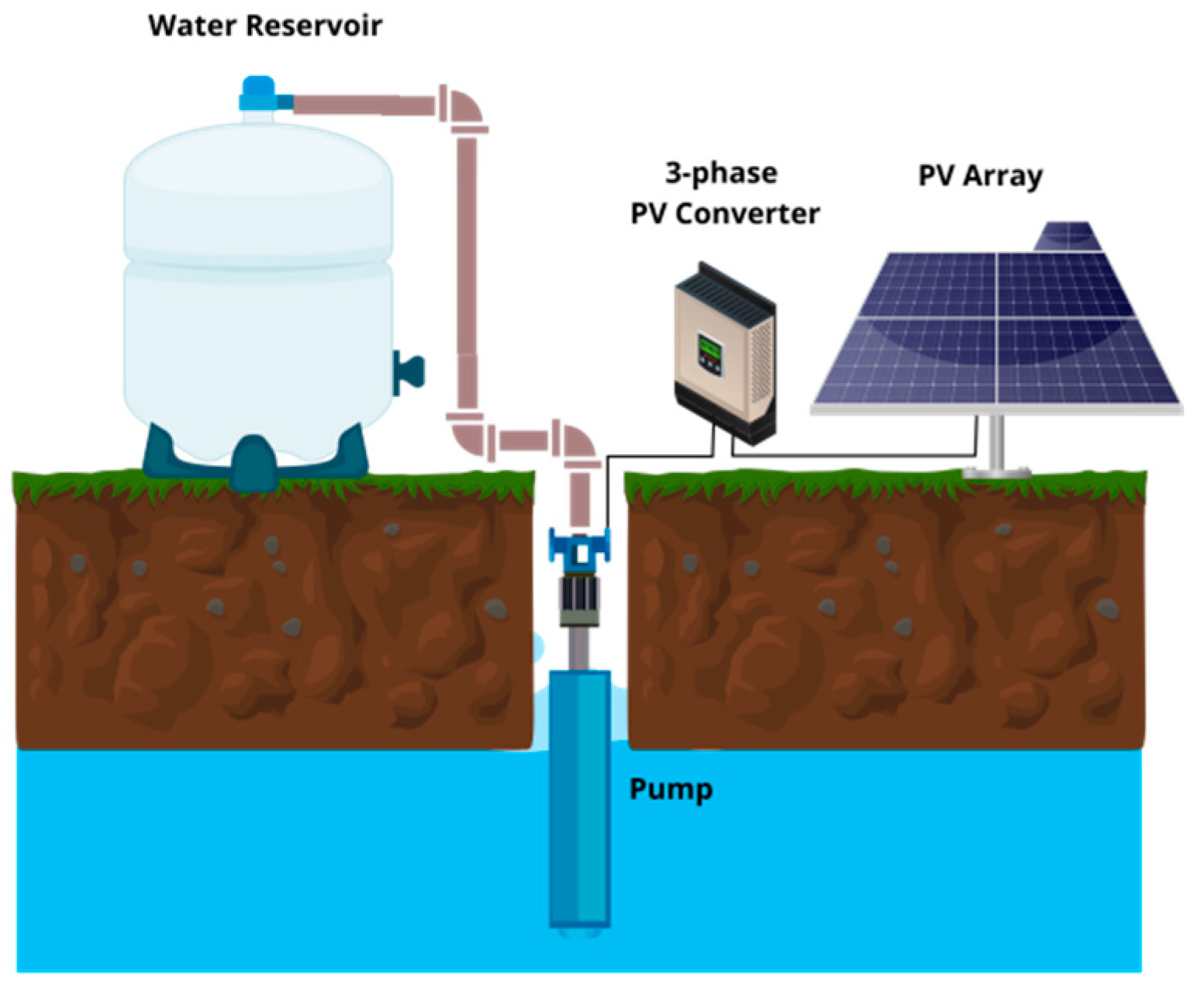
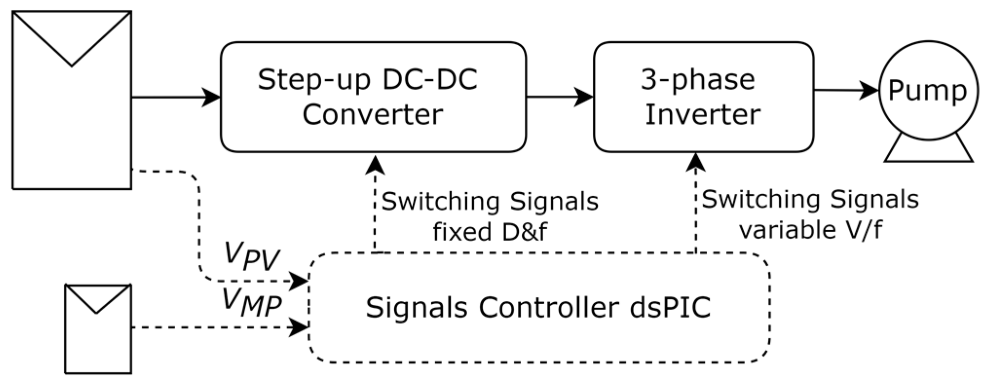
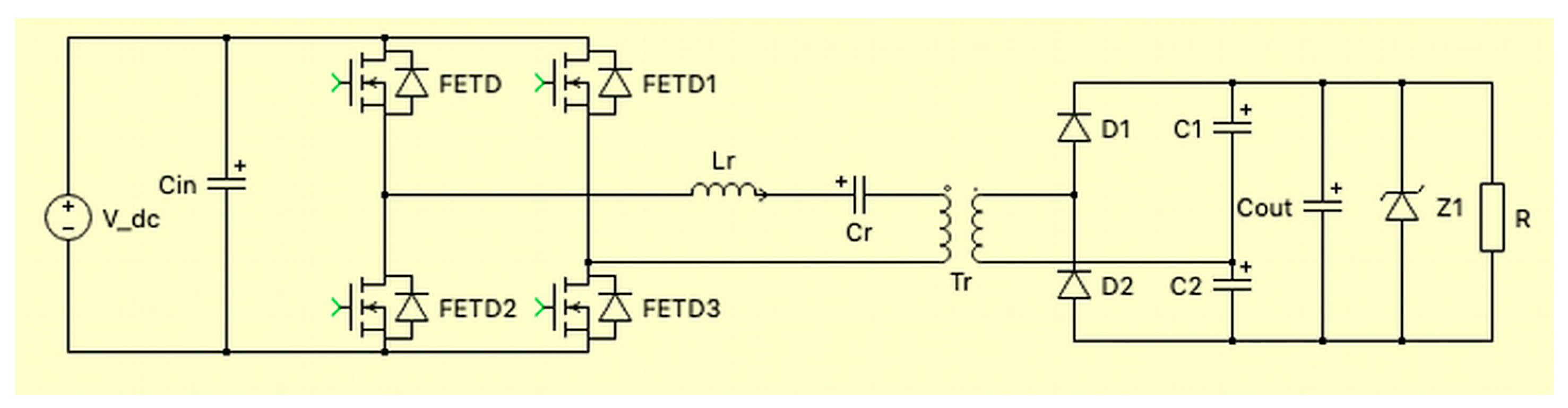
2.2. System Overview and Converter Design

There are several topologies available in the literature that were candidates for the voltage step-up stage of this converter. The following were considered: push–pull, half-bridge resonant converter [8], tri-state current source inverter [9], two inductor boost, forward converter. The LLC full-bridge converter presents some advantages over the other topologies, such as low voltage stress within the primary switches, viable transformers, easy-to-design LLC tanks, and low cost. When compared to the half-bridge topology, the full bridge demands more power switches; on the other hand, it has lower transformer current and no need for a capacitive voltage divider.
The design process for such step-up LLC converters is well detailed in [10]. For this system, the converter voltage input is around 63.4 V–78 V, while the DC Bus needs to be around 350 V–420 V for the three-phase inverter to be able to modulate at variable 230 V–60 Hz speed.
Figure 3 shows that instead of a full-wave rectifier, a voltage doubler rectifier was used, this modification allows for a transformer with half the number of secondary turns.
For the design of the LLC converter, it is necessary to be aware of the frequency operation range of the magnetics involved and the capacitance range of commercial capacitors with low equivalent series resistance (ESR); these capacitors are used in this converter as the resonant capacitance. Due to the transformer leakage inductance of the transformer being relatively low, it is convenient to add an extra inductor to compose the LLC tank. This extra inductance is a lot larger than the leakage inductance of the transformer; both are in series and sum up [11].
As the increase of switching frequency beyond 60 kHz causes exponential core losses, the resonant and switching frequency are chosen at around 60 kHz. It is necessary to find a balance between core losses and transformer dimensions [12]. The resonant capacitance is chosen to be in the range of 1 μ F–2 μ F. For the inductor, an iron powder core is used, while the transformer has a NEE ferrite core.
f r = 1 2 π L r C r
By solving Equation (1), the resonance elements are set as in Table 1.
Regarding the transformer design, the first step is to calculate the minimum primary turns ( N p ) when considering a specific commercial ferrite core. According to Equation (2), this calculation is based on the ferrite core maximum magnetic flux ( B = 0.15   G ) , the RMS voltage over the winding ( V R M S = 44.8   V ) , the resonance frequency ( f r = 58.7   k H z ) , and the cross-sectional area ( A e = 2.4   c m 2 ) .
N p = 10,000 V R M S 4 f r B m a x A e
The minimum N p for a conservative value of B is found to be 6. For the calculation of the secondary turns N s , Equation (3) is used, which resulted in 20 turns. In the equation, a multiplying factor ½ is used due to a voltage doubler rectifier present in the topology.
N s = N p × 1 2 × V o u t V i n n o m
For the generation of switching signals, a dsPIC is used. As the dsPIC needs a 3.3 V source for it is powering, while the IR2113 gate drives work at around 13 V, a strategy of auxiliary voltage source is made, as shown in Figure 4.

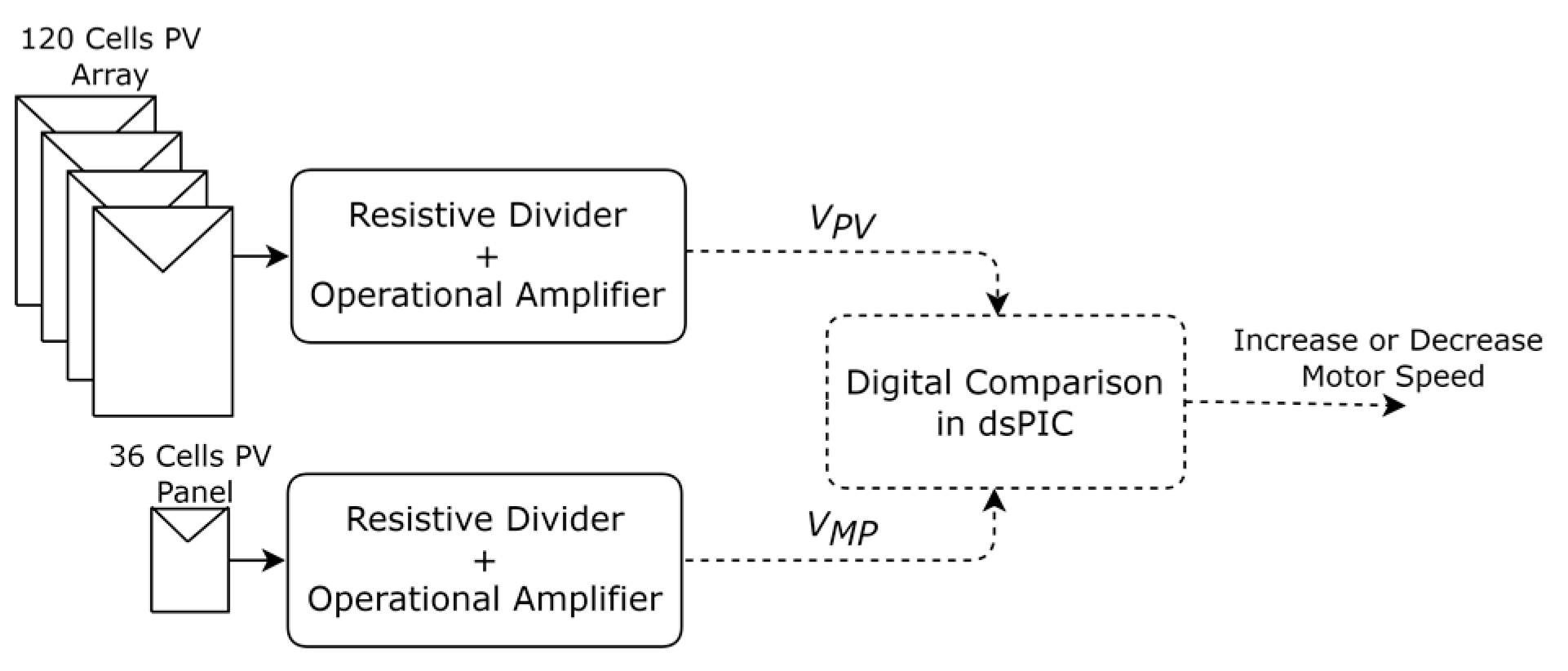
2.3. MPPT and V/f Control

The main MPPT techniques used are studied in depth in [13]. Even though the constant voltage is considered inaccurate in [13], it can be improved by using a low-cost 10 W auxiliary solar panel as an open circuit reference for the MPPT circuitry. That happens because the power panels and the auxiliary panel are all submitted to approximately the same solar radiation and ambient temperature; therefore, the auxiliary panel maximum power point voltage can be used as a reference. Details of this technique are shown in Figure 5. The resistive dividers are responsible for the gain of transformation of the 120 cells PV array to VPV and the 36 cells PV panel to VMP.

3. Results and Discussion

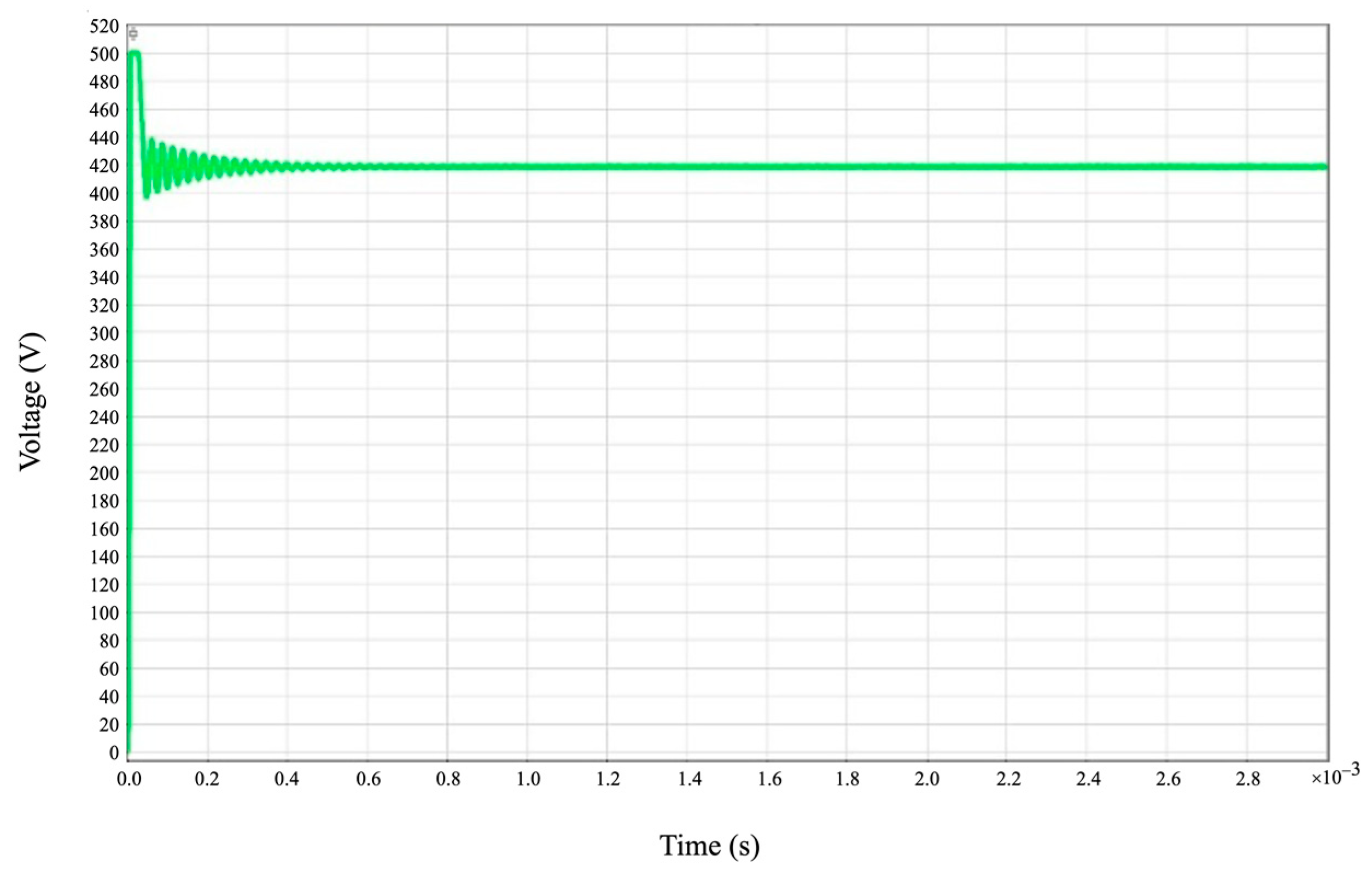
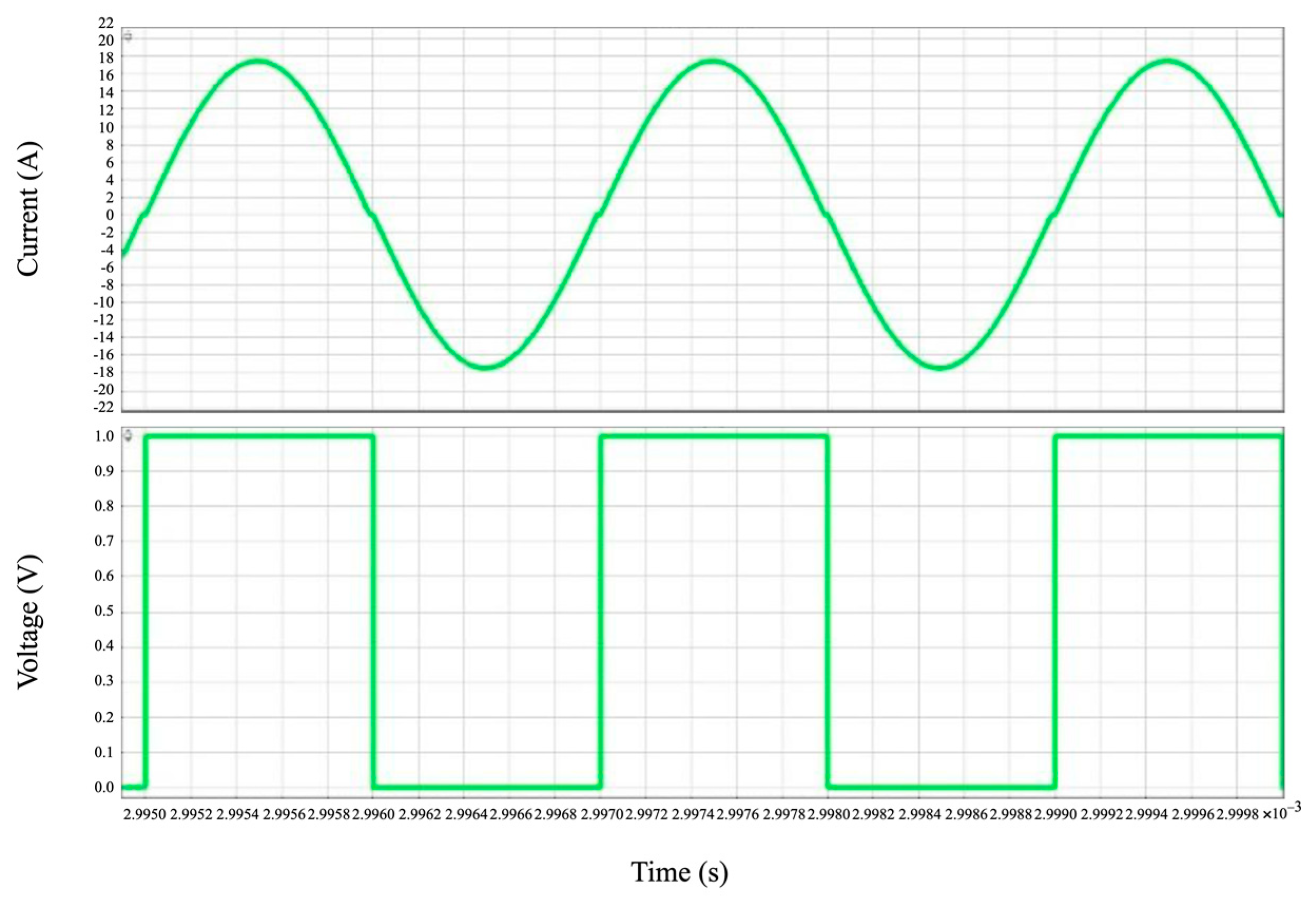
3.1. Simulation Results

To evaluate the DC bus voltage and transformer current waveforms, the LLC DC-DC converter is simulated in power electronics simulation software PLECS. The main simulation results are shown in Figure 6 and Figure 7.
The main components of the converter are shown in Table 2. They were chosen according to the design and simulation results.

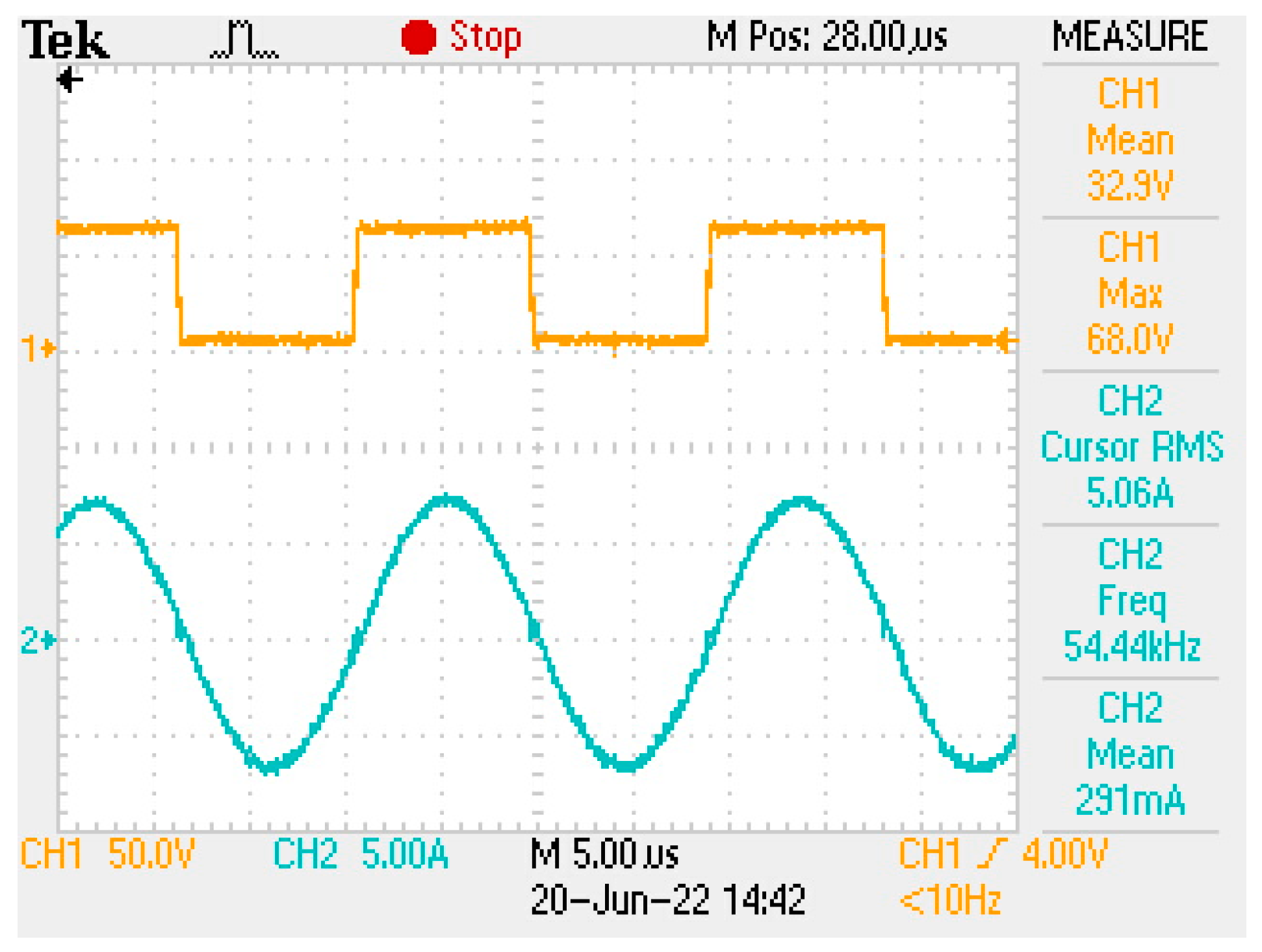
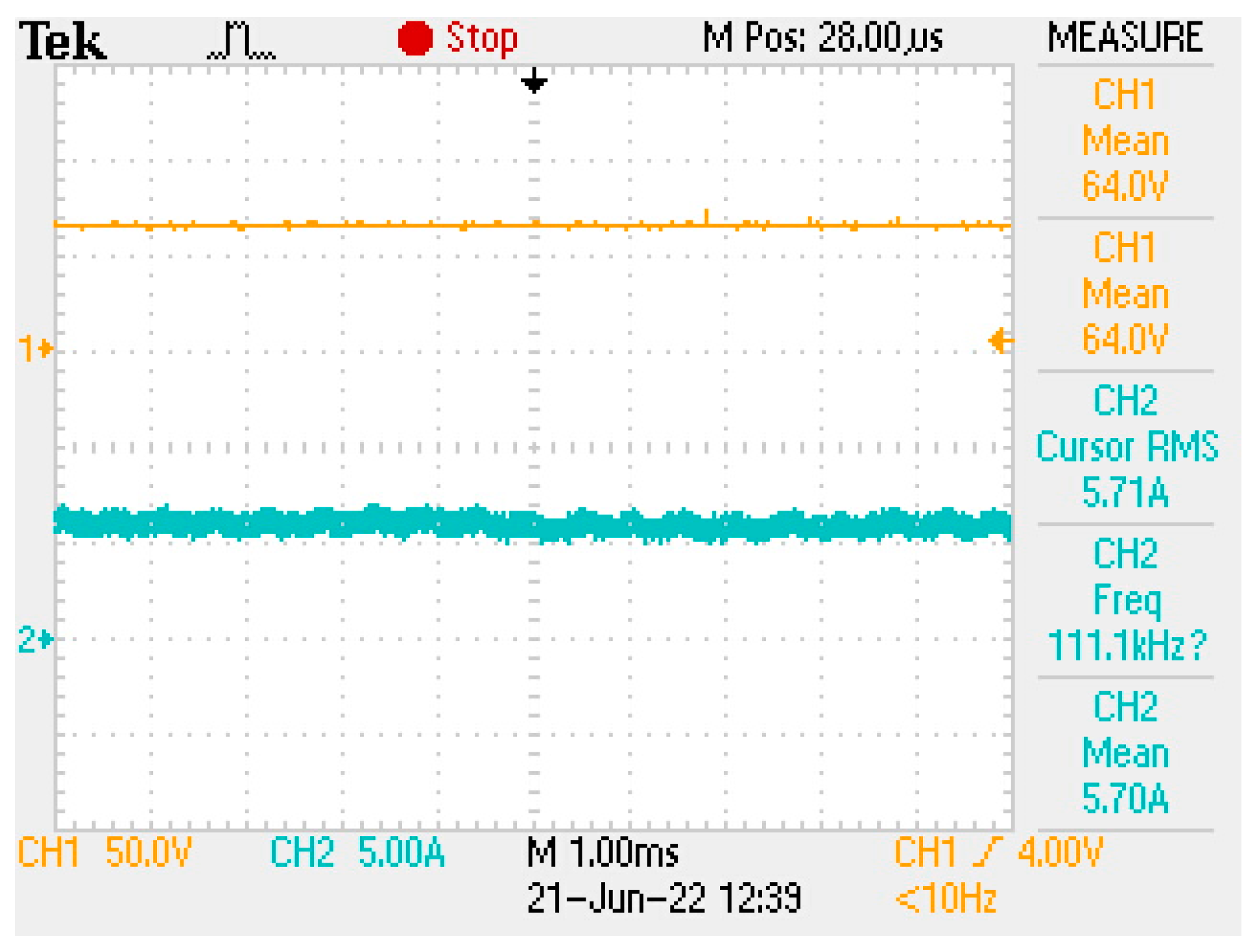
3.2. Experimental Results

After the initial design procedure and simulation, the converter was assembled in the printed circuit board (PCB) with the aim of performing experimental tests. The experimental results aim to answer the research questions.
In opposition to [14,15], we found that there was no need to control the switching signals duty cycle or frequency as these were set fixed in this case. This DC-DC converter is operated with no DC bus voltage feedback. The DC Bus varies in the range of 340 V–420 V according to the load, what is within the range for correct scalar control of the motor.
For the first indoor experimental test, the power source is a 63 V DC voltage source, and the load is a ½ hp water pump. The interest is in measuring the transformer current and the MOSFET drain-source voltage. These two measures indicate if the resonance is well designed for low switching losses at the MOSFETs.
The transformer current and MOSFET voltage are measured using an oscilloscope. Results can be seen in Figure 8 and Figure 9. It is interesting to notice that the current waveform is very sinewave-like, and the switch is turned on with near zero current.
In accordance with [16], we chose to use Silicon Carbide MOSFETs. In contrast to [17], no dissipative snubber was necessary. Figure 10 shows the input voltage and current at full load, while Figure 11 shows the output current at the motor/pump. The current spikes in Figure 11 are noise from the current probe.
After the design and construction of the converter, the frequency can be manually adjusted according to experimental results aiming to finetune the best frequency. As shown in Figure 8 and Figure 9, it was adjusted to 54.4 kHz. Compared to the calculated switching/resonance frequency, the frequency chosen experimentally is a little bit lower due to the transformer leakage inductance that was not measured; this inductance sums up with the external inductance. Therefore, the system would still be operational with the original resonance frequency. This manual adjustment would be made just in the development stage of the converter; for large-scale production, it is assumed that the leakage inductance would always be approximately the same and would not interfere with the production time. In [10], it is possible to understand if the switching frequency is above or below the resonance frequency. It is not possible to be exactly at the resonance frequency for the entire range of the load, as the resonance is dependent on the equivalent load.
For the second indoor experimental test, the power source is a solar array simulator, and the load is a ½ hp water pump. The solar array simulator (SAS) simulates a real photovoltaic panel; it decreases the voltage as the current increases, according to the datasheet curves. For this test, the converter increases the motor speed up to a nominal 60 Hz; the SAS voltage and current are shown in Figure 12. Figure 13 shows the power.
It is interesting to notice in Figure 12 that the voltage starts as an open circuit voltage; when the converter is started up, there is a spike of current; then the current increases slowly as the motor speeds up; then the current remains constant when it reaches nominal speed; finally, the converter is switched off, and the voltage comes back to open circuit.
Figure 14 shows the power converter layout assembled in an IP65 plastic box. A large heatsink was chosen due to the preference of not using a fan for heat dissipation.
Regarding the three-phase inverter, the line output voltage varies in the range of around 90 V to 220 V. The V/f control maintains approximately the same ratio for every frequency, which means that with 220 V, the frequency is 60 Hz, while for 110 V, the frequency is around 30 Hz. The pump startup frequency is set as 20 Hz.
The MPPT algorithm is set to update the motor speed for every 20 ms, while the speed step is about 0.1 Hz for every iteration. When tested in real conditions on a cloudy day, the motor speed never stops changing.
Outdoor experimental tests were performed, and the MPPT algorithm was tested on sunny and cloudy days. The MPPT was able to put the power of solar panels voltage at the same level of 10 W solar panel maximum power point voltage reference. This MPPT technique was also easy to implement (as it does not require a current sensor) and robust. The maximum water pressure measured with a 11-stage ½ hp water pump is 55 m head.

3.3. Discussions

Regarding the research questions presented in the Introduction of this work, it is now possible to answer them.
Can a resonant LLC DC-DC converter operate with a fixed duty-cycle and frequency? Yes. Even though the DC bus voltage varies within a relatively large range (340–420 V), it was not necessary to add a control loop to variate duty-cycle or frequency. The use of a resonant topology was shown as positive because there are no drain-source voltage spikes at the MOSFETs during steady-state operation.
Can Silicon Carbine MOSFETs be used to solve startup issues with a resonant LLC DC-DC converter? Yes. Several issues were faced when trying to implement this converter with 150 V Silicon MOSFETs, and when replacing them with 750 V Silicon Carbide MOSFETs, it was possible to overcome the startup problems. These problems occur during startup transient while the resonant capacitor is being charged, and the resonant inductor is being magnetized. During the transient period, there are voltage and current spikes. By using such a transistor, more voltage buffer space was added while keeping power losses low.
Is the use of an auxiliary panel appropriate to operate a constant voltage MPPT algorithm? Can this be used with a photovoltaic water pumping system? Yes. The use of a 10 W auxiliary panel was relatively easy to implement, and it can deliver interesting MPPT efficiency. The dynamics of the presented control strategy matches with the water pumping system and the dynamics of changing solar radiation and panel temperature. The converter was tested outdoors with the well pump inside a 100 L water tank. The tests were made in multiple conditions for multiple sunny and cloudy days. During sunrise and sunset, the converter starts working after/before there is a minimum amount of power to turn on the control circuits and the pump. It was possible to notice that the MPPT worked efficiently because the water pressure on the pump outlet was observed, and it reached a maximum value of 55 m.

3.4. Cost Analysis

Regarding the cost of the converter, it needs to be low enough to be able to compete with other alternatives available on the market. What could be found in the national Brazilian market was purchased locally, PCB and some hard-to-find electronics were imported. Table 3 shows the cost of the power converter in detail, while Table 4 shows the cost of the entire solar pumping system.
The costs considered are acquisition costs and no associated assembly and testing costs were calculated. Some aspects of this project help to keep the costs low, no battery is required [18], and differently from [19], no galvanic isolation or multilevel inverter is required.

3.5. System Feasibility

Regarding the feasibility of the system for the water requirements of a beef cattle farm in Brazil, some considerations are made. When it comes to water consumption, the average consumption used by local farmers is 50 L/animal/day. Based on a case study, an area of 200 animals is considered, resulting in a water consumption requirement of 10,000 L/day. The well depth found is 52 m. According to the hydraulic data provided by the water pump manufacturer, for an 11-stage ½ hp water pump, the water flow at nominal speed is 2600 L/hour at this depth. Therefore, it would take less than 4 h at a nominal speed to pump 10,000 L of water per day.
Regarding the solar input requirement, the solar panels plus power converter need to be sufficient to deliver the 220 V 60 Hz required by the ½ hp pump. In the south of the center-west region of Brazil, the average solar radiation is approximately 4 h of peak sun (1000 W/m2) per day. Considering that 4 × 280 Wp solar panels were chosen for this system, with two panels in series and two panels in parallel, it can be concluded that the system’s pump would work at nominal speed for solar radiations over 500 W/m2. This means that instead of 4 h of peak sun, around 8 h of solar radiation over 500 W/m2 can be considered. Based on these considerations, over 20,000 L would be pumped per day on sunny days, making the system feasible with a margin. A more complete model that predicts water flow and reservoir level according to solar input curves can be created for future works.

4. Conclusions

A photovoltaic groundwater pumping system is described, with its chosen components implying a high lifetime and its costs suggesting a market-friendly solution. The system converts solar energy into a consumer good essential for maintaining human life. The use of 750 V Silicon Carbide MOSFETs provides a solution for startup issues while minimizing power losses. The use of a fixed duty-cycle and frequency LLC DC-DC converter is possible for this application, considering the suitable transformer turn ratio. The DC bus voltage varies according to solar radiation and motor/pump speed but can be designed to work within an appropriate range. The proposed constant voltage MPPT algorithm can control the motor/pump speed based on sunlight radiation and temperature. Experimental tests and water requirements demonstrate that the system is suitable for a beef cattle farm in Brazil. When choosing a ½ hp water pump, it is important to consider using the well pump with the highest number of stages due to the minimum water pressure necessary to overcome the well height during periods of low solar radiation. This is in accordance with [20]. A high-volume water reservoir is essential for meeting water demand during periods of low solar radiation. Future works could include the creation of a model that predicts water flow and reservoir water level of this system according to solar radiation and temperature curves. Furthermore, a data logger could be used to track the operation of the converter during sunrise, throughout the day and during sunset. This way, the efficiency of MPPT operation would be monitored more accurately.

Author Contributions

Conceptualization, F.P. and R.B.G.; methodology, F.P.; software, F.P.; validation, F.P., N.D.d.A., R.B.G. and T.H.d.A.M.; formal analysis, F.P. and R.B.G.; investigation, F.P., R.B.G. and T.H.d.A.M.; resources, N.D.d.A. and R.B.G.; writing—original draft preparation, F.P. and R.B.G.; writing—review and editing, N.D.d.A. and T.H.d.A.M.; supervision, R.B.G.; project administration, R.B.G.; funding acquisition, N.D.d.A. and R.B.G. All authors have read and agreed to the published version of the manuscript.

Funding

This study was financed by the Research and Development Project—PD ANEEL: PD-06961-0010/2019.

Data Availability Statement

Not applicable.

Acknowledgments

The authors want to thank the Federal University of Mato Grosso do Sul—UFMS and the companies which sponsored the Research and Development Project—PD ANEEL: PD-06961-0010/2019.

Conflicts of Interest

The authors declare no conflict of interest.

References

  1. The United Nations World Water Development Report 2022: Groundwater: Making the Invisible Visible. Available online: https://unesdoc.unesco.org/ark:/48223/pf0000380721 (accessed on 10 May 2023).
  2. Energy Transitions: Lighting in Vanuatu 2014. Available online: http://hdl.handle.net/10523/4859 (accessed on 10 May 2023).
  3. Palmiro, F.; Rayudu, R.; Ford, R. Modelling and simulation of a solar PV lithium ion battery charger for energy kiosks application. In Proceedings of the 2015 14th IEEE PES Asia-Pacific Power and Energy Engineering Conference 2022 (APPEEC), Melbourne, Australia, 20–23 November 2022. [Google Scholar] [CrossRef]
  4. Maddalena, E.T.; da Silva Moraes, C.G.; Bragança, G.; Junior, L.G.; Godoy, R.B.; Pinto, J.O.P. A battery-less photovoltaic water-pumping system with low decoupling capacitance. IEEE Trans. Ind. Appl. 2019, 55, 2263–2271. [Google Scholar] [CrossRef]
  5. Caracas, J.V.M.; Farias, G.d.C.; Teixeira, L.F.M.; Ribeiro, L.A.d.S. Implementation of a High-Efficiency, High-Lifetime, and Low-Cost Converter for an Autonomous Photovoltaic Water Pumping System. IEEE Trans. Ind. Appl. 2014, 50, 631–641. [Google Scholar] [CrossRef]
  6. Chen, R.; Brohlin, P.; Dapkus, D. Design and magnetics optimization of LLC resonant converter with GaN. In Proceedings of the 2017 IEEE Applied Power Electronics Conference and Exposition (APEC), Tampa, FL, USA, 26–30 March 2017; pp. 94–98. [Google Scholar]
  7. Lu, J.; Tong, X.; Shen, M.; Yin, J.; Yuan, Y. The Phase Shifting Soft Startup of L-LLC Resonant Bidirectional DC-DC Converter Based on Current-Limiting Curve. Math. Probl. Eng. 2021, 9, 6632743. [Google Scholar] [CrossRef]
  8. Palmiro, F.; Pinto, J.O.P.; Pereira, L.H.; Godoy, R.B. Cost-effective photovoltaic water pumping system for remote regions communities. In Proceedings of the 2014 IEEE Energy Conversion Congress and Exposition (ECCE 2014), Pittsburgh, PA, USA, 14–18 September 2014; pp. 3287–3293. [Google Scholar]
  9. Kimpara, M.L.M.; Palmiro, F.; Bizarro, D.B.; Galotto, L.; Godoy, R.B. Three-phase Tri-State Current Source Inverter for photovoltaic energy stand-alone applications. In Proceedings of the IECON 2011-37th Annual Conference of the IEEE Industrial Electronics Society, Melbourne, VIC, Australia, 7–10 November 2011; pp. 1642–1647. [Google Scholar]
  10. Resonant LLC Converter: Operation and Design. Available online: https://www.infineon.com/dgdl/Application_Note_Resonant+LLC+Converter+Operation+and+Design_Infineon.pdf?fileId=db3a30433a047ba0013a4a60e3be64a1 (accessed on 10 May 2023).
  11. Park, C.W.; Han, S.K. Analysis and design of an integrated magnetics planar transformer for high power density LLC resonant converter. IEEE Access 2021, 9, 157499–157511. [Google Scholar] [CrossRef]
  12. Zhao, S.; Li, Q.; Lee, F.C.; Li, B. High-frequency transformer design for modular power conversion from medium-voltage AC to 400 VDC. IEEE Trans. Power Electron. 2017, 33, 7545–7557. [Google Scholar] [CrossRef]
  13. De Brito, M.A.G.; Galotto, L.; Sampaio, L.P.; Melo, G.D.A.; Canesin, C.A. Evaluation of the main MPPT techniques for photovoltaic applications. IEEE Trans. Ind. Electron. 2012, 60, 1156–1167. [Google Scholar] [CrossRef]
  14. Zhuang, Y.; Liu, F.; Zhang, X.; Diao, X.; Jiang, J.; Sun, J. Direct Frequency Control Based MPPT Algorithm of LLC Resonant Converter for Photovoltaic System. In Proceedings of the IEEE Energy Conversion Congress and Exposition (ECCE 2019), Baltimore, MD, USA, 29 September–3 October 2019; pp. 3402–3406. [Google Scholar]
  15. Wei, Y.; Luo, Q.; Mantooth, A. Comprehensive analysis and design of LLC resonant converter with magnetic control. CPSS Trans. Power Electron. Appl. 2019, 4, 265–275. [Google Scholar] [CrossRef]
  16. Çalışkan, E.; Ustun, O. Smart Efficiency Tracking for Novel Switch—LLC Converter for Battery Charging Applications. Energies 2022, 15, 1861. [Google Scholar] [CrossRef]
  17. Yoon, D.; Lee, S.; Cho, Y. Design Considerations of Series-Connected Devices Based LLC Converter. Energies 2020, 13, 264. [Google Scholar] [CrossRef] [Green Version]
  18. Mahjoubi, A.; Fethi Mechlouch, R.; Ben Brahim, A. A Low Cost Wireless Data Acquisition System for a Remote Photovoltaic (PV) Water Pumping System. Energies 2011, 4, 68–89. [Google Scholar] [CrossRef] [Green Version]
  19. Garcia-Reyes, L.A.; Beltrán-Telles, A.; Bañuelos-Ruedas, F.; Reta-Hernández, M.; Ramírez-Arredondo, J.M.; Silva-Casarín, R. Level-Shift PWM Control of a Single-Phase Full H-Bridge Inverter for Grid Interconnection, Applied to Ocean Current Power Generation. Energies 2022, 15, 1644. [Google Scholar] [CrossRef]
  20. Tripathi, P.R.; Thakura, P.; Laxmi, V.; Keshri, R.K. Stand-alone PV Water Pumping System based on high-gain resonant inverter fed induction motor serving two-head for permanent water supply. Int. J. Circuit Theory Appl. 2021, 49, 2494–2514. [Google Scholar] [CrossRef]
Figure 1. Photovoltaic groundwater pumping system.
Energies 16 04926 g001
Figure 2. Proposed photovoltaic groundwater pumping system.
Energies 16 04926 g002
Figure 3. LLC DC-DC converter with voltage doubler rectifier.
Energies 16 04926 g003
Figure 4. Auxiliary voltage sources.
Energies 16 04926 g004
Figure 5. Constant voltage MPPT technique for motor speed control.
Energies 16 04926 g005
Figure 6. DC bus Voltage simulation result.
Energies 16 04926 g006
Figure 7. Transformer current and switching signals simulation results.
Energies 16 04926 g007
Figure 8. Transformer current (blue)and MOSFET Drain-source voltage (yellow) at light load.
Energies 16 04926 g008
Figure 9. Transformer current (blue) and MOSFET Drain-source voltage (yellow) at full load.
Energies 16 04926 g009
Figure 10. Input voltage (yellow) and Input current (blue) at full load.
Energies 16 04926 g010
Figure 11. Output current (blue) at full load.
Energies 16 04926 g011
Figure 12. Input voltage (blue) and Input current (orange). Test with solar array simulator.
Energies 16 04926 g012
Figure 13. Solar Power. Test with solar array simulator.
Energies 16 04926 g013
Figure 14. Power converter.
Energies 16 04926 g014
Table 1. Resonance elements.
ItemSpecification
Capacitance— C r 4 × 470 nF = 1.88 μ F
Inductance— L r 3900 nH
Frequency— f r 58.7 kHz
Table 2. Main components of the converter.
ComponentsSpecification
Primary switches—SW1–SW4Mosfet SiC 750 V—UJ4C075018K3S
Input capacitor—C2 220   μ F 100 V electrolytic +
6   ×   1   μ F ceramic
Resonant inductor—L1~3900 nH, 5× AWG20 litz cable, 3× iron powder core
Resonant capacitor—C14 × 470 nF 630 V film
Transformer6:20 NEE 42/21/20
Rectifier diodes 30ETH06 30 A 600 V
Rectifier capacitors 6   μ 8 250 V polyester
DC Bus capacitors 3   ×   1   μ F 600 V polyester
Inverter mosfets Mosfet SiC 750 V—UJ4C075018K3S
Gate drives600 V IR2113
Table 3. Power converter cost.
ItemBRL Cost USD Cost
PCB 5.26
National electronics185.82
Imported electronics 20.92
Heatsink72.00
Box140.00
Electric Miscellaneous60.00
Iron powder cores20.40
TotalR$607.89122.73 USD
Table 4. Solar pumping system cost.
ItemBRL Cost USD Cost
Power converter607.89
4 × 280 Wp panels2560.00
10 W panel100.00
Water pump1600.00
TotalR$4867.89982.80 USD
Disclaimer/Publisher’s Note: The statements, opinions and data contained in all publications are solely those of the individual author(s) and contributor(s) and not of MDPI and/or the editor(s). MDPI and/or the editor(s) disclaim responsibility for any injury to people or property resulting from any ideas, methods, instructions or products referred to in the content.

