1. Introduction
1.1. Motivation
Energy is an essential requirement for the survival of humanity. The demand for energy continues to grow due to advancing technology and persistent needs. Furthermore, with the potential future electrification of the transport sector and the increasing power usage in smart homes, which currently account for 40% of global energy consumption, the demand for electricity is projected to further increase. Traditional utility grids predominantly rely on fossil fuels and contribute approximately 64.5% of the total power generation. Among these grids, the transportation and generating sectors are responsible for approximately 24% and 40% of the total carbon emissions, respectively [
1]. Many countries are facing a widening gap between their energy requirements and their capacities to meet such demands. This escalating energy demand necessitates the adoption of renewable energy resources (RERs) such as solar and wind power. In response, innovative strategies for power generation using RERs are increasingly developed to address the exponential rise in energy demand while simultaneously reducing costs and carbon emissions [
2,
3,
4].
The importance of energy conservation lies in its impact on reducing energy prices. Various innovations have been implemented in residential settings, falling into two main categories, namely power production systems and consumption-cutting technologies. While the installation of microgeneration units at homes is a viable option, utilizing existing infrastructure proves to be more cost-effective and reliable. Achieving this relies on intelligent management systems that can plan the operation of household appliances by powering them off when not in use [
5] and scheduling their usage during periods of lower energy costs to promote conservation. By being aware of their power consumption patterns, consumers can actively reduce their energy usage. In some countries, tariff accounting is based on demand, meaning that higher demand leads to higher pricing and vice versa. Hence, the system must allow for continuous monitoring of usage, facilitating two-way communication between power providers and customers. To achieve this, the so-called Internet of Things (IoT) technology is increasingly adopted [
6]. The IoT proves to be an ideal solution for long-distance communications as it enables data from loads and sensors to be sent to a cloud, providing users with easy access. The term “Energy Internet” is used to describe the integration of the IoT with energy-related systems, including microgrids (MGs) that incorporate RERs, energy management systems, and electrical loads [
7,
8,
9,
10]. The rollout of bidirectional smart MGs is recognized as a viable solution to meet the immense energy demand of the population by ensuring a continuous supply of electricity, even in the event of a main power grid failure [
11].
In this context, smart MGs are regarded as promising innovations for advancing the 21st century power grid. MGs have gained popularity due to their capacity for power generation, universal control, and digital communication, their self-monitoring capabilities, and their ability to operate autonomously or in connection with the utility grid. By managing the electricity market, controlling decentralized power supplies, and reconstructing infrastructure, MGs bring forth a new era of demand-side management (DSM). DSM, facilitated by the transformation from a traditional grid to an MG, enhances grid efficiency, reduces costly generation, alleviates load pressure, improves system reliability and sustainability, and optimizes system capacity without necessitating changes to its physical design. The integration of MGs and DSM concurrently is recognized as a viable path to achieve the objectives of mitigating carbon emissions to combat global warming and reducing energy costs through demand management [
12,
13,
14].
Typically, when consumer demand surpasses supply, costs can escalate, affecting all customers within the system. DSM plays a pivotal role in influencing electricity costs by reducing peak demand during periods of high electricity tariffs. Residential loads can be categorized as either shiftable or non-shiftable. DSM approaches involve adjusting consumer demand patterns to reshape the load curve by shifting shiftable appliances away from peak pricing hours. Consequently, DSM emphasizes energy-saving technological solutions, financial incentives, and billing tariffs, rather than focusing on enhancing the transmission and distribution infrastructure of the grid or constructing additional power plants.
Based on the above premises, the efficient scheduling of household electrical appliances presents a compelling opportunity to optimize energy consumption and reduce power expenditures. Accordingly, this paper aims to propose a viable and low-cost technique for household appliance scheduling by utilizing a time-of-use (ToU) tariff-based DSM approach coupled with load shifting. The motivation behind this research lies in the potential benefits it offers to both consumers and the overall energy system. By leveraging ToU pricing tariffs and a well-defined pricing timetable, this technique enables the identification of cost-effective periods for appliance operation, taking advantage of low peak, shoulder, and on-peak hours. Through the calculation of appliance operation durations and the consideration of minimal tariff periods and appliance waiting times, the proposed management technique optimizes the utilization of shiftable appliances. This system evaluates the energy produced by an MG alongside that generated by the main grid, providing a comprehensive assessment of energy sources.
1.2. Literature Review
The literature is rich in methods aimed at addressing energy management challenges through peak energy consumption and energy costs. For instance, the authors in [
15] have examined the effectiveness of proper electrical system installation and household energy management, presenting a reward-based IoT system for load control using, for example, Arduino microcontrollers. The proposed system enables users to track, modify, and control response loads dynamically through a mobile application. In [
16], a multi-agent system (MAS) is proposed for incentive-based load management in MGs, implemented using the Java Agent Development Environment (JADE). Another study [
17] has utilized the IoT technology to propose a DSM approach that considers load priorities and user preferences, effectively managing the operation of various appliances to keep total consumption within a specified threshold. As another instance, the study in [
18] has focused on the design and development of smart grids (SGs) by making efficient use of available resources with minimal modifications. Notably, it has emphasized the manufacturing costs of smart meters, power usage monitoring, and data transmission through Global System for Mobile (GSM) communication modules.
For IoT-enabled smart homes, the authors in [
19] have proposed load scheduling-based energy management to reduce energy costs and peak consumption while maintaining user comfort. More specifically, they have introduced a new paradigm of user priority through power utilization scheduling in demand response (DR) programs [
20,
21,
22]. In particular, in their paradigm, energy management controllers prioritize the activation and deactivation of home appliances based on their priorities and operational limits. In [
23], the authors have developed a MAS for a dynamic demand-side solution in a solar MG using Arduino microcontrollers and the IoT, employing a conventional control approach to manage the load and direct energy flow to and from the utility grid based on surplus and deficit conditions.
Another research stream focuses on the development of optimization-based algorithms tailored to the DSM. For example, the particle swarm optimization (PSO) algorithm is utilized to prioritize sustainable resources while reducing expenditures during emergencies in [
24], while simultaneously developing a new controller to schedule appliances and integrate RERs into virtual plants. In the context of SGs, the authors in [
25] have developed an optimization-based framework for smart homes that are connected to external renewable energy sources with the primary objectives of consumption reduction and cost saving.
In [
26], a novel real-time load controller is developed using an optimization scheduling method inspired by the binary tracking search algorithm. The objective is to save energy and reduce peak demand in homes by programming appliance usage based on the time of day, occupant comfort constraints, and other factors. Similarly, in [
27], a reinforcement learning algorithm is used to optimize energy use within residences, aiming to reduce electricity consumption across households. The algorithm utilizes data provided by smart meters, and the simulation results demonstrate a potential reduction in power costs ranging from 6.23% to 11.54%.
An effective load-shifting-methodology-based DSM is also proposed in [
28] that utilizes main grid resources within the smart grid milieu. The main grid is utilized only when MG generation is insufficient to meet the load requirements. Two newly developed meta-heuristics, namely the virulence optimization algorithm (VOA) and the earthworm optimization algorithm (EWOA), have also been employed in [
29,
30] for optimization-based load shifting within the smart grid context. These meta-heuristics have been shown to contribute to lower electricity bills and reduced electricity peaks in a load-shifting-based DSM program.
Moreover, to minimize costs, reduce peak consumption, and ensure customer comfort, Sahar et al. [
31] have also proposed a unique hybrid strategy that combines genetic algorithms (GAs), binary particle swarm optimization (BPSO), and ant colony optimization (ACO) methodologies for ToU pricing. The hybrid GA-BPSO has also been used and shown to be effective in DSM optimization applications [
32].
Table 1 offers a summary of the most salient previous studies in the literature while positioning this study within the context of prior work. The existing literature demonstrates a wide range of approaches and methodologies for addressing energy management challenges, including load control systems, MASs, IoT integration, scheduling algorithms, and optimization techniques. However, there remains a gap in the experimental implementation of load-shifting-based DSM and the comprehensive utilization of MG resources in conjunction with the main grid.
On the other hand, in the field of DSM, several studies have contributed valuable insights and methodologies related to decentralized demand response and efficient computation for load shifting. For instance, Hosseini et al. [
33] have focused on decentralized demand response in energy communities, incorporating flexible loads and shared energy storage systems. They have proposed a multi-block alternating direction method of multipliers (ADMM) approach to optimize energy consumption and load shifting decisions. Another study by Li et al. [
34] has addressed the efficient computation of sparse load shifting, emphasizing the importance of considering load sparsity for reducing computational complexity. Furthermore, Hosseini et al. [
35] have presented a robust optimal energy management strategy for residential microgrids, taking into account uncertainties in demand and renewable power generation. Their framework aims to minimize energy costs while ensuring reliable power supply. Whilst these studies provide valuable contributions to the field of DSM, it is important to highlight that this study adopts a centralized approach. While decentralized demand response, efficient computation for load shifting, and robust energy management strategies are all significant research areas, this study’s focus lies in the development and evaluation of a centralized DSM framework. By adopting a centralized approach, this paper aims to address specific challenges and optimize energy consumption in a controlled and coordinated manner. This distinction highlights the unique contributions and emphasis of this research, providing insights into the effectiveness and feasibility of a centralized DSM system in optimizing energy utilization.
1.3. Novel Contributions
This paper proposes a grid-connected smart MG with an Energy Internet-based price-incentive algorithm for DSM using a load-shifting strategy. The proposed algorithm aims to identify the most cost-effective tariff periods during which shiftable appliances can be shifted. Notably, as far as can be ascertained, there exists no prior work on the real-world implementation of such an algorithm. The proposed DSM program incorporates both price- and incentive-based DSM techniques. Therefore, the proposed algorithm shifts load appliances not only away from high-demand periods but also to times of lower prices. Further, the utilization of the Cayenne platform enables the monitoring of significant findings through the Energy Internet technology. Accordingly, the experimental implementation results validate the effectiveness of the aforementioned algorithm-based energy-management controller.
The following notable contributions are made in this paper:
The design and development of an experimental prototype of a renewable energy-driven smart DSM system: a prototype system is designed and implemented which combines renewable energy sources, such as solar photovoltaic (PV) panels, with a battery energy storage system (BESS) and Wi-Fi microcontroller units (MCUs). This experimental setup serves as a test-case system to demonstrate the integration of renewable energy resources and the proposed DSM framework.
The proposal of a hybrid price-incentive algorithm for shiftable appliances: a novel algorithm is introduced which aims to identify the most economical tariff periods for using shiftable appliances. This algorithm takes into account various characteristics, including the minimum tariff, previous appliance usage, duration of operation, and supply priority. By considering these factors, the algorithm dynamically adjusts the time period for each shiftable appliance, optimizing energy consumption and cost-effectiveness.
The integration of applications for embedded systems and the IoT: this paper focuses on the integration of embedded systems and the Internet of Things (IoT) to regulate residential demand consumption. By utilizing the Energy Internet platform and the Cayenne platform, it enables the real-time monitoring of overall system parameters, such as energy expenditures and consumption, from anywhere. This integration provides users with convenient access to critical information, empowering them to make informed decisions regarding their energy usage.
These contributions collectively highlight the development of a renewable energy-driven smart DSM system, the introduction of a hybrid price-incentive algorithm for shiftable appliances, and the integration of embedded systems and the IoT for the real-time monitoring and regulation of residential demand consumption.
In addition, to benchmark the effectiveness and impact of DSM on energy consumption, energy purchased, and electricity bills with and without DSM, the proposed method is applied to various MG power generation scenarios.
1.4. Paper Organization
The remainder of this paper is organized as follows.
Section 2 provides a comprehensive description of the overall problem studied.
Section 3 introduces the proposed load shifting-technique-based DSM method.
Section 4 presents the problem formulation, wherein the specific objectives and requirements of the proposed system are defined. In
Section 5, a detailed description of the system design and development process is provided.
Section 6 focuses on the experimental implementation of the proposed system. The implementation results and findings are presented in
Section 7. The paper concludes in
Section 8 by summarizing the key findings, contributions, and implications, as well as highlighting potential areas for future work.
2. Problem Statement
This paper addresses two crucial concerns related to energy management in residential settings, aiming to provide a more holistic solution for households seeking effective and cost-efficient energy utilization. The first concern revolves around the construction of an MG based on RERs. The primary objective is to establish an energy infrastructure that can sufficiently meet the power demands of a household. By incorporating renewable energy sources such as solar PV panels and wind turbines, the MG ensures a sustainable energy supply. Furthermore, the MG is designed to allow households to operate all their appliances seamlessly, providing a reliable and uninterrupted power source.
To improve the functionality of the MG, this paper leverages the concept of the Energy Internet. By leveraging Energy Internet technology, households can actively monitor and manage their energy consumption in real time. This continuous monitoring enables users to assess the system’s performance, identify potential areas for improvement, and make informed decisions regarding energy usage. Accordingly, through the integration of the Energy Internet, households gain greater control over their energy consumption patterns, leading to more efficient utilization of available resources.
The second concern addressed in this paper focuses on reducing power consumption costs through the implementation of a load shifting technique based on DSM. DSM plays a pivotal role in optimizing energy usage by strategically shifting appliance operation to off-peak hours when electricity tariffs are lower. To this end, this study introduces a hybrid pricing incentive algorithm within the DSM framework. The proposed algorithm analyzes various factors including the minimum tariff, appliance usage history, duration of operation, supply priority, and local generation of MGs. By considering these factors, the algorithm determines the most cost-effective times for appliance usage, effectively reducing electricity bills.
The modeling of the problem involves making certain assumptions about the appliances and their energy requirements. Detailed analyses are conducted to understand the energy consumption patterns of different home appliances. Special attention is given to appliances powered by a solar PV system with BESS backup, as these setups enable households to make effective use of solar energy and store excess power for later use. By exploring the impact of solar PV system and BESS integration, the study provides important insights into optimizing energy management and reducing reliance on the utility grid.
Overall, this study aims to empower households with the knowledge and tools to make informed decisions regarding energy management. By adopting an RERs-based MG and implementing the proposed load shifting technique based on DSM, households can significantly reduce power consumption costs while ensuring a sustainable and reliable energy supply. The study contributes to the broader goal of achieving energy efficiency and sustainability in residential settings, offering experimental solutions for households to minimize operating costs and make environmentally conscious choices.
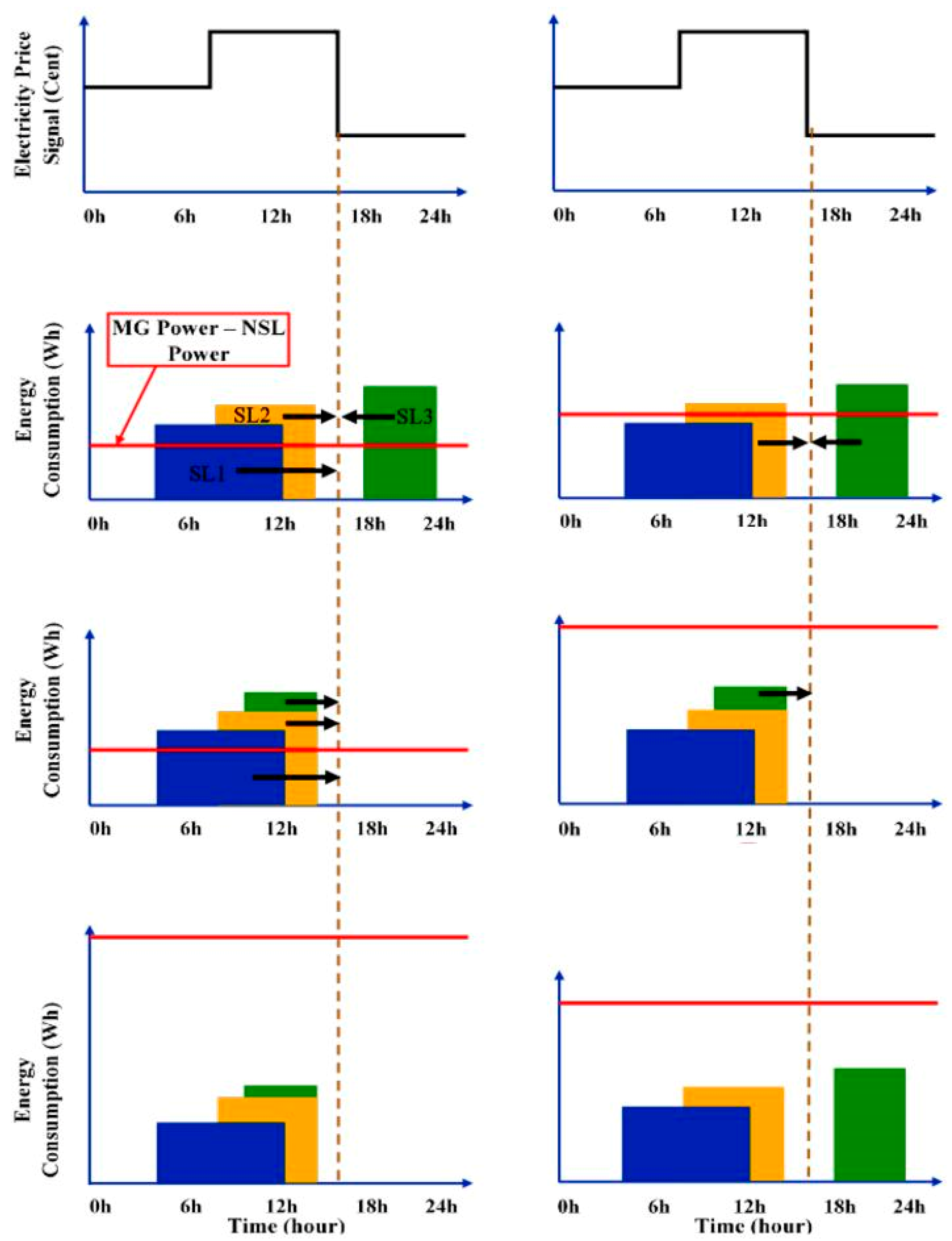
3. Proposed Load-Shifting-Technique-Based DSM
Figure 1 provides an illustration of the proposed load-shifting-based DSM strategy in various scenarios. Within the system, there are two categories of loads: non-shiftable loads (NSLs) and shiftable loads (SLs). NSLs operate continuously for 24 h and cannot be shifted to different time periods. Initially, these loads are supplied by the MG, utilizing grid power only if necessary. On the other hand, SL appliances can be in one of the following four states: waiting for their designated time, waiting for the minimum tariff, being supplied by the MG, or being supplied by the main grid. The state of each appliance is determined by a flag set to either “0” or “1”. A flag value of “1” indicates that the appliance is currently in a waiting state, while a value of “0” indicates that it is operational.
SL appliances enter a waiting condition if their scheduled times or the minimum tariffs have not yet arrived. If the MG can only supply one or two out of the three adopted SLs, and their designated periods have arrived, the remaining SL appliances will be switched to operate from the main grid at the minimal tariff. Pre-scheduled load appliances need to be shifted at the beginning of the lowest price period, regardless of whether they fall within or outside the time zone of the lowest price.
To ensure the continuous monitoring of the system’s parameters, the Energy Internet and the Cayenne platform are utilized. The system employs relay-driving units to automatically initiate and terminate the power consumption of the selected load appliances while adhering to the predetermined time for each appliance. An overall diagram of the system’s implementation is illustrated in
Figure 2, while the proposed algorithm’s flowchart is presented in
Figure 3. These visual representations provide a clear overview of the system’s functionality and the steps involved in the associated load shifting process.
More specifically,
Figure 3 demonstrates that the proposed load-shifting algorithm prioritizes the shifting of all shiftable loads due to insufficient excess power in the MG after supplying the non-shiftable loads. Consequently, the algorithm schedules the shiftable loads to the beginning of the electricity tariff period with the lowest price. On the other hand,
Figure 3 illustrates a scenario where the excess power of the MG after serving the non-shiftable loads is inadequate to accommodate all shiftable loads. In this case, the algorithm selectively shifts specific shiftable loads to the lowest tariff period. Additionally,
Figure 3 demonstrates that when the excess power of the MG after serving the non-shiftable loads is sufficient to supply all the shiftable loads at their pre-scheduled times, the algorithm does not perform any load shifting.
By implementing this algorithm-based load shifting approach and utilizing continuous monitoring through the Energy Internet, the energy management system achieves efficient control of energy consumption, cost optimization, and improved scheduling of load appliances.
4. Problem Formulation
4.1. Mathematical Framework for the Scheduling of Appliances
Appliances can be categorized as non-shiftable or shiftable depending on their energy consumptions, operation hours, and the preferences of the end user. Shiftable appliances can be modified to operate in any time scale. The total energy consumption of such appliances,
, can be determined as follows:
where
represents the time slots,
is the index of the current appliance,
denotes the total number of shiftable appliances,
is the power consumption of the appliance during time slot
, and
represents the ON/OFF state of the shiftable appliance
in the timeframe defined by the starting time (
) and ending time (
), as shown below:
The daily consumption cost of shiftable appliances,
, can then be calculated thus:
where
is the price of electricity.
The load profiles of routinely operating appliances, also known as fixed or non-shiftable appliances, cannot be altered in any manner. The daily energy needs of such appliances,
, can be expressed as follows:
where
is the total number of non-shiftable appliances,
is the index of appliances,
is the power consumption of each non-shiftable appliance, and
is the ON/OFF status of each non-shiftable appliance
in the shifting timeframe denoted by the starting time (
) and ending time (
), as shown below:
The costs associated with the operation of non-shiftable appliances per day,
, can be expressed as follows:
The aggregate energy use,
, of shiftable and non-shiftable appliances and their associated costs,
, are also calculated in Equations (7) and (8), respectively.
Further, to determine the cost of energy imported from the utility grid,
, the sum of energy used by all loads can be deducted from the MG power and then multiplied by the corresponding pricing signal, as below:
where
and
are power flows associated with the MG’s transactions with the utility grid, solar PV, demand, and battery power, respectively, while the constant
is calculated by using the following equation:
The MG has the highest priority for supplying NSLs and SLs, followed by the utility grid. Accordingly, utility grid shiftable load (
), MG shiftable load (
), utility grid non-shiftable load (
), and MG non-shiftable load (
) are given by the following equations:
where
and
represent the ON/OFF states of the grid and MG switch relays, respectively, which are connected to the associated shiftable loads and can be calculated as below:
4.2. Constraints
The consumption of load demand following the load shifting process (over the entire day) should match the daily load demand prior to scheduling, as represented by the following equation:
where the term (
is the consumption of load demand following the load shifting process and
is the daily load demand prior to scheduling.
Additionally, at each time-step
, the number of shifted appliances should be less than or equal to the number of shiftable appliances, as expressed in Equation (24):
where
denotes the shifted appliances and
represents the shiftable appliances.
To ensure that the power demand (
) remains within the limit of the maximum MG power (
), when deactivating the DR program, load shifting techniques are used to shift shiftable loads into utility if the demand exceeds MG power. This is imposed by the following constraints:
Furthermore, the scheduled operation of both shiftable and non-shiftable loads is restricted to specific times of the day. After the activation of DSM, the duration of each load period should remain the same as its pre-DSM duration, as defined in Equations (27) and (28):
During the load shifting process, some shiftable load appliances may remain unused. This constraint, known as the idle constraint, can be defined by Equation (29).
Moreover, the power balance, a critical constraint, is determined by the following equation:
where
is the utility grid power.
The solar system constraint is also as follows:
Finally, despite the battery’s significant running expenses, it is essential in off-grid systems as it stores excess solar energy for later onsite use. However, when a battery is discharged by nearly 100% of its capacity, it becomes completely depleted, leading to the following limitation:
5. Test-Case System Setup
Figure 2 provides an overview of the test-case system setup. According to the pre-defined rule-based scheduling algorithm, the appliances in the system are supplied by either the MG system or the utility grid. The system consists of a total of five appliances, including two non-shiftable and three shiftable appliances. The MG system comprises several components, such as solar PV panels, a BESS, inverters, a Buck Boost (BB) converter, and a solar PV controller. Additionally, the proposed system incorporates a main MCU and several load-measurement-based MCUs. The main controller’s role involves data collection, data processing, and uploading the results to the cloud. For this study, the controllers were implemented using Wi-Fi ESP32 MCUs, which possess two processing cores. The ESP32’s Central Processing Unit (CPU) is a low-power Xtensa 32-bit LX6 microprocessor [
36]. Moreover, the MCU is equipped with built-in wireless networking, Bluetooth, and Ethernet capabilities. The controller receives information about the current, voltage, and power consumption across the load through PEZ-004T modules. Electronic switches and relays respond to instructions from the MCU.
The DSM power demand is influenced by the adopted-load appliances. The centralized controller effectively manages the system’s operational conditions based on power generation availability and the market price. Smart appliances, controllers, and the energy management center are interconnected using the Energy Internet technology. The proposed Energy Internet platform facilitates the monitoring and collection of data from the SG. That is, it seamlessly integrates energy resources and load appliances.
The setting-up process began by supplying power and connecting the main MCU to a nearby wireless network. The proposed DSM technique autonomously manages the energy consumption of load appliances. Additionally, a dedicated controller was installed for each appliance to monitor voltage, current, and power consumption, as depicted in
Figure 4. The controller reports the power output to a remote server. To activate or deactivate the relay switches of the loads, the controller utilizes the output of the proposed rule-based DSM control process. Once the controller has processed all the load appliances and transmitted the data to the cloud platform, the cycle repeats in real time. In the subsequent subsections, a comprehensive description of the development of the system setup is provided.
5.1. MG Subsystem
In the utilized technique, the load appliances are powered by a solar PV-based MG system, which additionally integrates a BESS. The BESS provides backup power to ensure uninterrupted power supply. It also helps reduce associated operational costs through strategic charging and discharging. Specifically, the battery bank is charged during periods of excess solar PV generation and discharged during nighttime or when solar irradiance is reduced due to factors such as cloudy weather. This reduces the reliance on the power grid and eliminates the need for diesel generators, resulting in reduced operational expenses and increased self-sufficiency.
The BB converter is controlled to maintain a stable output voltage of 13 V, which is suitable for charging a 12 V, 100 Ah battery bank. The BB controller receives signals from both the input and output of the converter’s power circuit. Consequently, the controller adjusts the pulse signal of the switch based on the voltage at the input and output terminals. The DC power output from the battery is then directed to the inverter, which converts it into AC power. This AC power is utilized by the shiftable and non-shiftable load appliances connected to the system. The operational dispatch scheduling of these appliances follows the proposed power management system.
In the buck mode, the buck converter reduces the output voltage. The switch Ta is activated by gate pulses, while Tc remains off. The buck converter operates in the following condition: Ta on and Tc off. The duty cycle is adjusted to achieve the desired output voltage (). When the switch Ta is closed, the input voltage () is applied, allowing the supply current to flow through Ta while Tb remains off. That is, the input supplies power to the load. Equation (33) mathematically expresses the governing equation for the inductor voltage in this circumstance.
The switch remains off for (
seconds, where
represents the duty cycle. Once Ta is turned on and the inductor’s voltage triggers the conductivity of switch Tb, the inductor starts to discharge the stored energy. The inductor voltage can be calculated thus:
where the duty cycle (
) is given by
.
In the boost mode, the boost converter increases the output voltage. The boost converter operates in the following two modes: (i) Ta is always on and Tb is off, and (ii) Tc receives regulated gate pulses. The duty cycle is adjusted to achieve the desired output voltage. When transistor Tc is closed, switch Td is opened, and hence the inductor carries current. In this mode, the inductor acts as a capacitor, storing energy for later use. The cycle repeats when power is switched back on. Equation (35) mathematically expresses the governing equation for the inductor voltage in this circumstance.
When time step equals
, the switch Tc is opened and Td is closed. At this point, the inductor has accumulated enough current, and it begins to release the energy into the input current, which then flows through the load. The cycle repeats when power is switched back on. The inductor voltage in this circumstance is determined by Equation (36):
where the duty cycle (
) is given by
.
In the buck–boost circuit, the ultimate relationship between the input and output voltages can be expressed as follows:
Consequently, the relationship between the input and output currents (
and
) can be expressed thus:
In order to minimize the ripple of the peak current (
) and ensure that the capacitor does not resonate with the inductor, it is important to select an inductor with a high value. Equation (40) describes the relationship between the inductor value and the ripple of the peak current. Additionally, the value of the capacitor should be chosen to minimize the ripple voltage (
). The specific values for the inductor (
) and output capacitor (
) can be determined using Equations (40) and (41) [
37,
38,
39,
40].
The BB converter depicted in
Figure 5 employs two PI controllers, each with specific transfer functions described by Equations (42) and (43). These controllers are designed to regulate the output voltage and achieve a stable operating condition. The parameters of the PI controllers, namely
= 100 and
= 0.1 for the buck converter and
= 40 and
= 0.001 for the boost converter, have been fine-tuned through trial and error. Their role is to facilitate the charging of the adopted battery bank from the solar PV system, which consistently generates an output voltage of 13 V.
5.2. Electrical Measuring Sensors
To accurately measure the voltage and current signals, a circuit is constructed based on the specifications of the power source and controller. The load is supplied with 220 V/50 Hz power, requiring the main grid source to provide the same voltage and frequency. However, the MCU’s maximum input voltage is limited to 3.3 V DC. To measure the voltage across a source, the circuit shown in
Figure 6 is utilized.
For current sensing, a current transformer (CT) sensor is employed to detect the flowing current. The output signal of the CT sensor needs to be conditioned to match the input range of the MCU’s analog ports, which accept values between zero and below the maximum voltage of the analog-to-digital converters (ADCs). The circuit in
Figure 6 is responsible for current measurements and consists of the following two main parts:
Burden resistor (R3) and CT sensor: When using a “current output” type CT sensor such as the YHDC SCT-013-000, a burden resistor is employed to convert the current signal into a voltage signal.
Voltage divider for biasing (R1 & R2): The voltage divider is employed to adjust the input voltage to the MCU.
This configuration allows for precise voltage and current measurements and facilitates their compatibility with the MCU for further processing and analysis.
The specific component values for the current and voltage sensors are provided in
Table 2. Additionally, to establish the wireless sensor network, the proposed load measurement unit consists of five smart meter nodes, each equipped with an MCU and PEZM-004T sensor as depicted in
Figure 4. The PEZM-004T module is responsible for measuring various parameters of the load appliance, including voltage, current, power consumption, and frequency. Continuously monitoring the power usage of each appliance, the smart meters transmit this data to the main MCU for the execution of the proposed DSM program.
5.3. Relay-Drive Unit
The relay-driving unit for each load appliance is depicted in
Figure 7. This unit operates on the principle of electromagnetism. When the relay coil is energized, it functions as a magnet, causing a change in the position of its switch. The circuit powering the coil is separate from the component controlling the ON/OFF power flow. As a result, it is possible to drive the 5 V relay with a 3.3 V signal from the MCU using a transistor drive circuit, while the other end of the relay controls power to a 220 V appliance.
The two sides of the drive unit, each equipped with five-channel relays, are responsible for managing the associated household-level appliances. The first side handles power flow from the MG to the corresponding loads, while the second side manages power flow from the utility grid. As shown in
Figure 7, the MCU, based on the proposed DSM algorithm, sends a control signal to each pair of relays, with only one of these relays active at a time. This allows the corresponding load appliance to be powered by either the MG or the utility grid.
The relays used in this setup are typically normally closed (NC). The transistor serves as the triggering component. When the MCU applies a high signal to the base terminal of the transistor, the relay is activated. Transistor circuits that employ a common emitter configuration can drive small relays without any issues. In this design, a bipolar junction transistor (BJT) is utilized to operate a 5 V relay coil. To dissipate the back electromotive force (EMF) generated when the transistor turns “OFF” and protect the transistor from damage, a flywheel diode is placed across the terminals of inductive loads such as relays.
5.4. Energy Internet and the Cayenne Platform
The Internet of Things (IoT) encompasses a technological framework that empowers devices or entities, commonly referred to as “things,” that possess distinct identities to proficiently perceive, engage, and accumulate data and establish connections with other devices via the Internet. The concept of the Energy Internet involves integrating the IoT with community energy systems such as MGs, enabling the remote management and monitoring of these systems. Cayenne is an IoT platform [
41] that offers programmers, engineers, and students the ability to develop various IoT applications. It simplifies and expedites the process of creating IoT devices, supporting both mobile and web-based platforms. It is compatible with most MCUs. The Cayenne platform [
42] provides features such as a drag-and-drop widget-based dashboard, access to device data, and the remote management of IoT projects.
For communication between the system and the server, the message queuing telemetry transport (MQTT) technique is employed over TCP/IP sockets. The MQTT is a lightweight publish/subscribe network protocol designed for low-bandwidth and high-latency networks. In the MQTT, resource-constrained IoT devices can publish data related to specific topics to an MQTT message-broker server. The broker then forwards the information to clients who have subscribed to the corresponding topics. In the system under consideration, the Cayenne dashboard serves as the MQTT message broker.
Accordingly, this paper presents an open-source IoT-based electricity monitoring system. The ThingsBoard IoT server functions as an MQTT broker, and a MQTT client on the ESP32 is used to transmit sensor data from the MCU to the server via a local Wi-Fi connection. This communication mechanism ensures prompt data transfer.
Figure 8 provides an overview of the data transfer process.
In the proposed system, the Cayenne platform is utilized in conjunction with the MQTT as follows:
A main MCU is responsible for operating the Mosquitto broker, which is essential for implementing the MQTT protocol.
Cayenne, an automation platform that supports MQTT, operates on the same MCU. This allows the MCU to subscribe to specific topics and receive messages from other IoT devices. It can also publish messages on designated topics, enabling communication with other devices.
Cayenne facilitates the development of a user interface (UI) that enables users to control outputs and view sensor values through charts.
Additionally, ESP32 MCUs function as MQTT clients, enabling them to both publish and subscribe to topics.
These MCUs are connected to load appliances and sensors within the system.
Cayenne subscribes to the sensor data transmitted by these MCUs and displays the readings on the UI.
By leveraging the Cayenne platform and the MQTT protocol, the system establishes a communication framework where devices can exchange data and provide a user-friendly interface for controlling outputs and monitoring sensor values.
6. Experimental Setup
The proposed MG system and DSM architecture were tested in experimental settings. The system consists of two NSLs and three SLs that simulate real domestic loads typically found in residential buildings. The load values considered for the NSLs were 300 W and 400 W, while the load values considered for the SLs were 500 W, 600 W, and 700 W.
The DSM program, integrated into the overall system, adjusts the energy consumption of the unscheduled shiftable loads based on factors such as waiting time for the appliance, waiting time for the data transmission, and whether the appliance is supplied by the MG or the utility grid. By optimizing energy consumption, the system reduces energy expenses and prevents excessive load stress during peak demand periods.
Figure 9 shows the actual implementation and testing of each load appliance using the measurement unit, which includes the PZEM-004T unit for measuring load current, voltage, power, and energy. These readings were applied to the MCU as depicted in the figure.
The reader is referred to the
Supplementary Materials accompanying the paper for more details on the real-world implementation of the proposed system, including a discussion of the main control unit, driving unit, BB circuit, control circuit, and inverter.
7. Experimental and Numerical Results
7.1. Experimental Results
Table 3 presents the results of six different cases that were tested to analyze the system’s response based on variations in MG generation, operating hours, and durations of the SL appliances under consideration. The figures in these cases are scaled so that one minute represents one hour.
The reader is referred to the
Supplementary Materials accompanying the paper for more detailed experimental results, including a detailed discussion of the voltage, current, and MG power profiles across the different cases studied.
Figure 10 shows the input and output voltage characteristics of the BB converter circuit during testing. The input voltage range was adjusted from 10 V to 19 V, simulating solar PV conditions. The graph demonstrates that the proposed control mechanism maintains a stable output voltage of 13 V, except in the transition region between the buck and boost operation when the input voltage reaches 13 V (which is the reference voltage). In this transition region, the output voltage momentarily drops to 12.3 V.
Figure 11 illustrates the duty cycles of the buck and boost converters as the input voltage varies from 10 V to 19 V. When the input voltage exceeds the target output voltage (13 V), the buck converter is activated to lower the voltage, and the duty cycle increases as the input voltage decreases. Conversely, when the input voltage drops below 13 V, the boost converter is activated to raise the voltage to 13 V, and the duty cycle adjusts accordingly.
These figures demonstrate the performance of the BB converter in maintaining a stable output voltage of 13 V within the specified input voltage range, utilizing both buck and boost converter operations as necessary. The control mechanism effectively regulates the output voltage despite variations in the input voltage, ensuring the reliable and consistent performance of the BB converter.
7.2. Numerical Results
Table 4 provides a summary of the implementation results for all the cases studied. The table provides data on MG generation, purchased energy, and daily and monthly costs, as well as savings associated with the adoption of the proposed DSM framework.
Based on the results presented in
Table 4, it can be seen that in all cases, the implemented solution leads to significant savings in energy expenses, with cost savings of at least 50% where there are power imports in the relevant no-DSM scenario. The specific details and values of the savings may vary depending on the case and the parameters considered, but the overall trend is consistent across all cases.
More specifically, cases 1 and 4 demonstrate significant cost savings when DSM is implemented, with cost reductions of 55.93% and 64.38%, respectively. This indicates the effectiveness of the proposed hybrid price-incentive algorithm in optimizing energy usage and minimizing expenses for shiftable appliances.
Similarly, cases 2 and 5 exhibit notable cost savings of 52.94% and 66.667%, respectively, reinforcing the positive impact of DSM in reducing energy expenditures. These results validate the applicability and benefits of the proposed framework across diverse scenarios.
In contrast, cases 3 and 6 show no cost savings when DSM is applied. It can be seen that these cases involve MG power generation without any power imports. Therefore, there is no need for demand shifting or optimization, resulting in zero cost saving. While these cases do not demonstrate immediate cost benefits, they highlight the adaptability of the proposed DSM framework, which can dynamically respond to different system configurations and requirements.
Moreover, across the different cases presented in
Table 4, variations in MG power generation and purchased power are evident, showcasing the diverse system configurations and energy requirements. The MG power ranges from 1000 W to 2000 W, reflecting different energy generation capacities in the studied scenarios. Similarly, the purchased power varies from 0 W to 10.4 W, highlighting the varying degrees of reliance on external power sources and the potential for optimizing energy usage through the implementation of the proposed DSM framework.
The table serves as a comprehensive overview of the outcomes achieved through the adoption of the proposed DSM approach. It highlights the cost saving potential and the effectiveness of the implemented solution in reducing energy expenditures in different scenarios.
8. Conclusions and Future Work
This paper has introduced and experimentally implemented a load-shifting-based DR program to effectively incentivize consumers to reduce their consumption costs and energy usages during peak demand hours. In addition to helping replace conventional electricity generation assets with RERs, as demonstrated through the implementation, this work makes a significant contribution to the research on DSM by incorporating comprehensive modeling and incorporating explicit constraints related to the implementation.
The proposed algorithm optimizes the operation of shiftable appliances by strategically timing their usage, taking into account factors such as waiting for the minimal tariff, waiting for the optimal time to operate appliances, and accurately calculating the operational duration of each appliance. The system includes five residential appliances, with two categorized as non-shiftable and three as shiftable. The proposed load-shifting-based DSM allocates power from the MG to both the non-shiftable and shiftable appliances if the MG has sufficient capacity. In cases where the MG’s power supply is inadequate, the proposed system intelligently shifts the remaining shiftable loads to periods of low-priced grid energy.
To ensure the accurate monitoring of energy usage when consumers are unable to verify their energy meters’ accuracies on-site, the proposed system incorporates the Energy Internet technology. This technology facilitates energy control and continuous monitoring whilst additionally improving consumer awareness and enabling energy savings. The implementation of the proposed DSM program in residential buildings has proven to be effective in reducing electricity costs and establishing a consistent power usage schedule for smart appliances.
By addressing the challenges of peak demand and optimizing energy consumption, this paper contributes to the broader objectives of energy efficiency, cost reduction, and sustainability. The findings offer practical solutions for consumers to actively participate in DR programs, reduce their environmental footprints, and make informed decisions regarding energy consumption.
Although this study has provided valuable insights into load shifting-based DSM for smart MGs, there are several avenues for future research that warrant exploration. Firstly, the development and implementation of advanced optimization algorithms can enhance the efficiency and effectiveness of load shifting strategies. The integration of renewable energy sources and energy storage systems within the load shifting framework presents an opportunity to improve the sustainability and performance of smart MGs. Real-world case studies and field trials are also needed to further validate the applicability and scalability of the proposed load shifting approach. Additionally, exploring the incorporation of demand response strategies and their interaction with load shifting can further optimize DSM. Integration with other smart grid technologies, such as advanced metering infrastructure and grid automation, should also be investigated for intelligent energy management. Lastly, conducting cost–benefit analysis and considering economic factors can provide insights into the financial viability of, and incentives for, implementing load shifting strategies. These areas of future research will contribute to the advancement and practical implementation of efficient energy management solutions in smart MG systems.


