Article

Use of Park’s Vector Method for Monitoring the Rotor Condition of an Induction Motor as a Part of the Built-In Diagnostic System of Electric Drives of Transport

1
Department of Electromechanics and Rolling Stock of Railways, Kyiv Institute of Railway Transport ofState University of Infrastructure and Technologies, 04071 Kyiv, Ukraine
2
Department of Transport and Handling Machines, Faculty of Mechanical Engineering, University of Zilina, 01026 Zilina, Slovakia
3
Department of Electrical Engineering, Volodymyr Dahl East Ukrainian National University, 91000 Kyiv, Ukraine
4
Department of Ship Power Units, Auxiliary Mechanisms of Ships and their Operation, Kyiv Institute of Water Transport of State University of Infrastructure and Technologies, 04071 Kyiv, Ukraine
*
Author to whom correspondence should be addressed.
Energies 2023, 16(13), 5109; https://doi.org/10.3390/en16135109
Submission received: 4 June 2023 / Revised: 26 June 2023 / Accepted: 30 June 2023 / Published: 2 July 2023
(This article belongs to the Special Issue Power System Analysis Control and Operation)

Abstract

:
The article is devoted to the use of Park’s vector method for operational control of the rotor condition of induction motors of traction and auxiliary drives of railway rolling stock. In the course of the analysis, it was established that in order to increase the reliability and efficiency of the operation of vehicles, it is necessary to improve and implement diagnostic systems for monitoring the current state of the most damaged elements of induction electric motors built into the drive. This paper presents the development of a new approach to monitoring the state of a squirrel-cage rotor, which is based on the use of Park’s vector approach. In the course of the research, the issue of taking into account the asymmetric power supply of the engine during the diagnostic period during industrial operation was solved, which affects the accuracy of determining the degree of damage to the rotor. On the basis of the conducted research, the algorithm of the module for diagnosing the state of the squirrel-cage rotor of an induction motor has been developed for practical use in the built-in on-board systems of vehicles, which allows us to determine the degree of damage and monitor the development of the rotor defect during operation, including in automated mode.

1. Introduction

1.1. Motivation and Relevance

Increasing the operational efficiency and reliability of vehicles is an important modern problem, which depends not only on the fulfillment of logistical tasks but also on ensuring the safety of all types of transportation. The development of new, and the improvement of existing systems of current diagnosis of the condition of electrical equipment of vehicles is the main factor in solving this issue. Prompt detection of damage to elements of vehicle equipment provides an opportunity to take timely measures to eliminate or replace them during pre-planned repair or maintenance. A greater share of transport equipment failures, taking into account the difficult operating conditions, is due to the electric motors of drives of various mechanisms and devices, where the main element is the electric motor.
At present, induction motors with squirrel-cage rotors of various capacities are used mainly as part of the main and auxiliary equipment of modern vehicles.
They are used as traction engines in railway transport, for driving compressors, machine-fans used for cooling traction engines, and for other equipment on rolling stock of railways and water transport [1,2,3,4]. Despite the fairly high reliability of induction electric motors with a squirrel-cage rotor among other types of electric motors, they are variously vulnerable to damage that affects their performance and failure during operation [5,6,7]. Especially for the operation of the transport infrastructure, the reduction of emergency failures is an important influential factor in the implementation of logistics technologies [8]. In the locomotive industry, the assessment of the state of road safety and the reliability of transportation in most cases is carried out while taking into account the volume of work performed by the locomotive; that is, relative indicators of the volume of transportation are used [9]. The development and implementation of systems for the continuous monitoring of the state of the main elements of induction electric motors during their operation will increase the reliability and efficiency of the use of vehicles and decrease emergency failures.

1.2. Literature Review

The problems of controlling the current state during the operation of induction motors are the subject of research by many scientists. The authors of the research use various methods for monitoring the state of electrical machines, however, the need to monitor data on the state of the engine during operation, to predict the uptime remains relevant [10,11]. Thus, in [12], a method of constant monitoring of the condition of an induction motor using the analysis of electrical characteristics is proposed. The given technique is capable of predicting various types of failures, i.e., rotor failures, stator phase misalignments, and power cable failures in the early stages. The authors of [13] cite a study of defects that cause changes in the vibration signature over time. The methods of vibration monitoring considered in the work allow for diagnosing the condition of the electric machine from such damages as bearing defects and wear of the rotor and stator. However, research [14] indicates a number of limitations when using vibration diagnostic methods for industrial conditions. Ref. [15] gives an overview of the methods of early diagnosis of induction motor faults based on sounds and acoustic emission for four types of damage: bearings, rotor, stator, and element connections. Effective results of diagnostics of the main elements of an induction motor are obtained using current methods, which seem to be the most appropriate for practical implementation and use in diagnostic monitoring systems that meet modern operational requirements. The authors in [16] cite a study on engine diagnostics using the spectral characteristics of the engine stator current and engine speed. The diagnosis of the main elements of the engine–stator, rotor, and bearings–was performed using an automatically adjusted algorithm of reference vectors with arbitrary characteristics. Ref. [17] presents the results of research on the example of diagnosing damage to the rotor of an induction motor by five different techniques of signal processing using the stator current. The most effective results are obtained by Park’s vector approach and the Hilbert transformation method. However, the use of the Hilbert transform method involves a quality power system used in stationary conditions, i.e., bench tests of equipment.
Works [18,19,20] show the effectiveness of using the current method of Park’s vector approach to detect multiple malfunctions of induction motors. The main difference from the simple spectral analysis of current signals in the formation of Park’s vector module spectra is that any characteristic frequency of the amplitude-modulated signal is taken into account in Park’s vector spectrum only once. The harmonics in the current spectrum, which correspond to different types of faults, differ from each other. Thus, the detection of characteristic harmonics in the current spectrum reliably and unambiguously indicates the presence of specific defects in the electric machine. In [21], the authors presented the results of studies on the effective use of the Park vector method for diagnosing an interturn short circuit in the stator winding with the determination of the number of closed turns in a low-quality motor power supply system.
Thus, Park’s vector method is the most effective and promising current method for detecting engine damage in the early stages for use in monitoring systems. However, the identification of malfunctions of various engine elements with the determination of the type and degree of their damage for various power and load conditions using Park’s vector approach is complex and requires further research. The main disadvantages of using Park’s method is the difficulty of detecting damage in the idling mode and its identification with an asymmetric power system. When using this method in the built-in monitoring systems of transport equipment, it is not expected to establish malfunctions in the idle mode. Conducting research on the development of control modules for the main elements of an induction motor for use in the built-in systems of on-board diagnostics of the induction electric machines of vehicles using Park’s vector method is a relevant and promising modern task.

1.3. Contribution

This article is devoted to the development of an algorithm based on the proposed method of determining damage to the squirrel-cage rotor winding of an induction motor. Park’s vector approach is used to detect core rotor damage. Damage to the rotor is determined by the thickness of the ring of the Park’s pattern. The proposed algorithm takes into account the power supply of the machine from a non-sinusoidal and asymmetric voltage system, which is relevant for diagnostics in industrial conditions. Identification of the degree of damage to the rotor is determined by recalculating the stator currents to the orthogonal circular basis and calculating the difference between the maximum value of the Park’s vector for the outer circle and the minimum value for the inner circle. The use of Park’s method makes it possible to obtain information about the current state of the engine rotor from the moment of damage and to control the degree of development of the defect during operation. This will allow early diagnosis of damage to the rotor winding as part of the diagnostic system of transport equipment during the operation of induction motors to predict the period of trouble-free operation. The use of Park’s vector approach has also shown effective results for diagnosing the stator winding and mechanical damage of an induction motor and can be considered one of the most reliable and convenient diagnostic methods.

1.4. Organization of the Paper

The work has the following structure: in Section 2, an analysis of the damage of the main elements of the induction motor is carried out with a more detailed consideration of rotor damage; Section 3 presents the theoretical principles of Park’s vector approach, constructs the Park’s vector diagram by means of mathematical modeling, and develops a methodology and algorithm for determining the degree of damage to the squirrel-cage rotor winding for use in built-in diagnostic systems of transport; Section 4 provides a discussion of the obtained results and the direction of further scientific research; conclusions are presented in Section 5.

2. The Main Elements of Monitoring the State of an Induction Electric Motor

The main elements of the engine that require state control during engine operation, which are among the most necessary to be included in the diagnostic monitoring system according to modern review studies, are stator winding, squirrel-cage rotor winding, and bearings [22,23].
According to the operational statistics [12,16,22], a quantitative analysis of the damage of asynchronous motors with a squirrel-cage rotor was carried out, the averaged results of which are combined into groups taking into account the most frequent failures and are presented in the Figure 1.
The largest share of failures of an induction motor with a squirrel-cage rotor (47%) is a consequence of damage to the stator winding. The main cause of failures is the occurrence of a turn-to-turn short circuit in the winding phase [20,21,24]. Turn-to-turn short-circuits refer to defects that are difficult to diagnose in the early stages, in which the induction motor continues to work with the deterioration of performance characteristics and energy indicators. At the same time, this defect can develop over time, and when a certain number of short-circuited turns is reached, insulation breakdown occurs as a result of which the electric machine fails. From this, it follows that the presence of a turn-to-turn short-circuit control module in the stator windings in the diagnostic system built into the drive is a necessary component. To determine the turn-to-turn shorting of the stator winding, a number of studies using current methods are presented [6,16,17]. The most effective results were obtained using the Park’s vector method [19,20,21]. In [21], the authors presented research on the use of the Park’s vector method to determine the number of closed turns in the stator phase winding of an induction motor using stator currents. In continuation of these studies, in [23], an algorithm and a functional scheme were developed for the practical implementation of the stator winding state control module to the diagnostic embedded system based on Park’s vector approach.
The proportion of bearing damage is 21% of all electric machine failures (Figure 1). Given the small size of the air gap, bearing defects eventually lead to the engagement of the rotor with the stator, which leads to significant consequences in the condition of the engine. In addition, the appearance of vibration due to damage to the bearing has a destructive effect on all elements of the engine structure. Various methods of vibration diagnostics are widely used to control the vibration state of an electric machine.
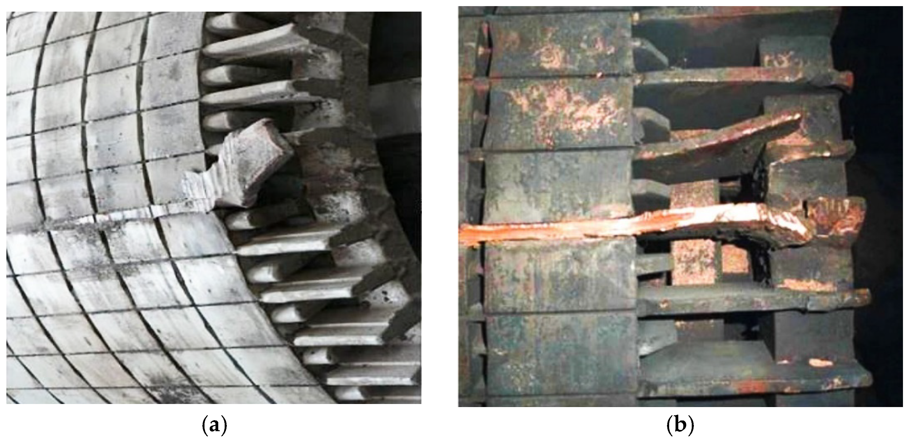
Another important structural element of an induction motor, which affects the reliability of the machine and is subject to monitoring, is rotor winding. During operation, the rotor is exposed to centrifugal forces, thermal expansion, shock current loads, and electrodynamic forces, and in some cases, the “squirrel cage” of the rotor loses its structural integrity. Damage to the rotor winding, according to the given general statistics (see Figure 1), makes up 12% of engine failures, but for powerful traction engines, rotor failures have significantly greater values. Damage to the rotor winding manifests in the form of the breakage of some rods or the destruction of contact in the rods of the “squirrel cage”. Structurally, the rods of the “squirrel cage” at the exit from the rotor grooves are connected to short-circuited rings located at some distance from the rotor core on both sides. When the rotor rotates, significant mechanical forces occur, which contribute to the creation of rod breaks at the exit from the rotor core or near short-circuited rings, especially during the start-up or limit load periods of rotors with copper or brass rods. For rotors with a winding made of aluminum, rod breaks occur more often in the grooves. Figure 2 shows images of rotor damage for various “squirrel cage” designs.
When operating machines with a broken “squirrel cage” structure, pulsation of currents occurs in the stator with a slip frequency, which creates vibration and affects the torque of the machine. At the same time, the frequency of rotation of the rotor fluctuates even with changes in small loads.
The occurrence of a contact failure in individual rods leads to an increase in the load on other rods remaining in the structure of the “squirrel cage” and increases their heating. Increased overheating during start-ups and significant engine loads leads to further destruction of the rods of the rotor winding structure, leading to emergency engine failure. In addition, the separated rods, under the action of centrifugal forces, are prone to displacement and exit from the grooves in the direction of the air gap (see Figure 2a,b), which leads to their engagement with the winding or the stator core and additional financial costs during engine restoration. The necessary current monitoring of the state of the rotor winding during operation as part of the built-in diagnostic system will reduce the probability of emergency failure and contribute to the timely identification of the appearance of a defect before the development and failure of the equipment. To solve the problem of early detection of the type and degree of damage to the rotor winding with a poor-quality power supply system in industrial conditions, the most effective is application of current diagnostic methods [17].

3. Development of an Algorithm for Determining the State of the Squirrel-Cage Rotor Winding of an Induction Motor

3.1. Using the Park’s Vector Method for Rotor Diagnostics

A number of works [21,25,26] of modern researchers are devoted to the use of Park’s vector approach, which belongs to current diagnostic methods for diagnosing elements of electric machines and drives.
The basis of Park’s vector approach is the transformation of the three-phase coordinate system of the stator currents into a two-dimensional moving system (dq-coordinates). The trajectory described by the end of the created vector on the coordinate plane with the corresponding axes of the stator current Isd and Isq when the power supply frequency changes has diagnostic signs of both electrical and mechanical engine defects.
Park’s vector currents Isd and Isq are determined from ratios based on the previously measured stator phase currents IA, IB, and IC [17]:
Isd = 2 3 IA 1 6 IB 1 6 IC
Isq = 1 2 IB 1 2 IC
Then, in the dq-coordinate system, the Park’s vector for the engine describes a figure centered at the origin according to the equation:
I ¯ s = Isd + J I s q
In the presence of a working electric machine, all currents are balanced and have no deviations from the normal mode. Then, under the condition of power supply from a strictly symmetrical voltage system, the Park’s vector pattern has a regular circle centered at the origin of the dq system coordinates [18,19,20].
Depending on the degree of damage to the stator winding, rotor winding, bearings, or a violation of the symmetry of the supply voltage system, three-phase stator currents result in a changed form of the Park’s vector pattern [27]. Despite the simplicity of damage detection using Park’s vector approach, the identification of different types of damage from a graphical representation of the presence of off-state modes of operation is too difficult. The vector pattern is affected by the quality of the power supply, the engine’s operating mode, the type of load, and many other factors. The most effective results were obtained for diagnosing the stator with the determination of the number of closed turns in case of a turn-to-turn short circuit in the phase of the stator winding, taking into account a poor-quality power supply system [21]. In these studies, the authors developed an algorithm for the practical use of the module for establishing the state and degree of the stator winding as part of the built-in diagnostic system [23]. The construction of a Park’s vector ring is provided using a mathematical model of an induction motor with the addition of a Park’s vector hodograph block.
The considered principle of using the Park’s vector method also makes it possible to determine the defects of the rotor winding of an induction motor with high accuracy. In [26], the authors presented a study of the influence of this type of malfunction on the phase current of the machine using the Park’s vector transformation method with analysis using complex wavelets. Determining the defect by the considered method is possible for stationary and bench conditions without the influence of external interference, especially if the induction motor operates at low slip values, when the characteristic frequency components of the rotor fault are very close to the main frequency component. The use of this method does not allow determination of the state of the rotor during operation with poor engine power. The development of this study is given in [18,26,28], where the analysis of the graphic drawing of the Park’s vector in case of rotor damage is carried out using different approaches. In the studies cited in [26] regarding the diagnosis of rotor rod breakage in induction motors, an increase in the width of the Park’s vector ring is used using more complex signal processing methods. In this work, it is shown that the result of defect detection depends on the magnetic poles and the number of rotor grooves, for which it is necessary to introduce a new approach with signal filtering, which greatly complicates the operational determination of the type of damage, and it is difficult to implement control in an automated mode. The authors of [28] use the deformation of the Park’s vector pattern as an indicator for predicting the condition using different magnetic saturation in a working and faulty induction motor with a squirrel-cage rotor for rotor diagnostics. This approach does not allow us to accurately identify the degree of damage to the rotor and does not take into account the changes in parameters associated with a poor power supply system. This issue is partially resolved in [29], where the conducted studies established that the degree of failure depends on the width of the ring of the Park’s vector pattern and gradually increases as the severity of the rotor malfunction increases. By monitoring the relative width of Park’s vector patterns, it is possible to identify rotor defects and control their development in an automated control mode. The authors propose to measure the width of the ring by monitoring the amplitude of a specific frequency in the frequency spectrum of the Park’s vector module, where rotor faults create spectral components in the left and right parts of the main frequency spectrum of linear currents. Control of these sidebands in the current spectra leads to an increase in the width of the Park’s vector trajectory. However, the work does not take into account the effect of an asymmetric system of voltages on the change of spectral components, which are informative for assessing the degree of damage to the engine rotor.
Figure 3 shows the difference between the Park’s vector patterns for an undamaged AIR132 M4 engine with a power of 11 kW (Figure 3a) and with simulated damage to the rotor rods (Figure 3b) with a symmetrical power supply system. A simulation model of an induction motor with a squirrel-cage rotor, made in the MATLab 2018b software environment and presented in [21,30] with the established adequacy of the simulation results [31], was used to construct the hodograph of the Park’s vector. In order to obtain reliable research results, a stable mode of operation of the engine without the influence of transient processes was considered. 2018b

3.2. Development of a Technique for Determining Rotor Damage by the Park’s Vector Hodograph Method

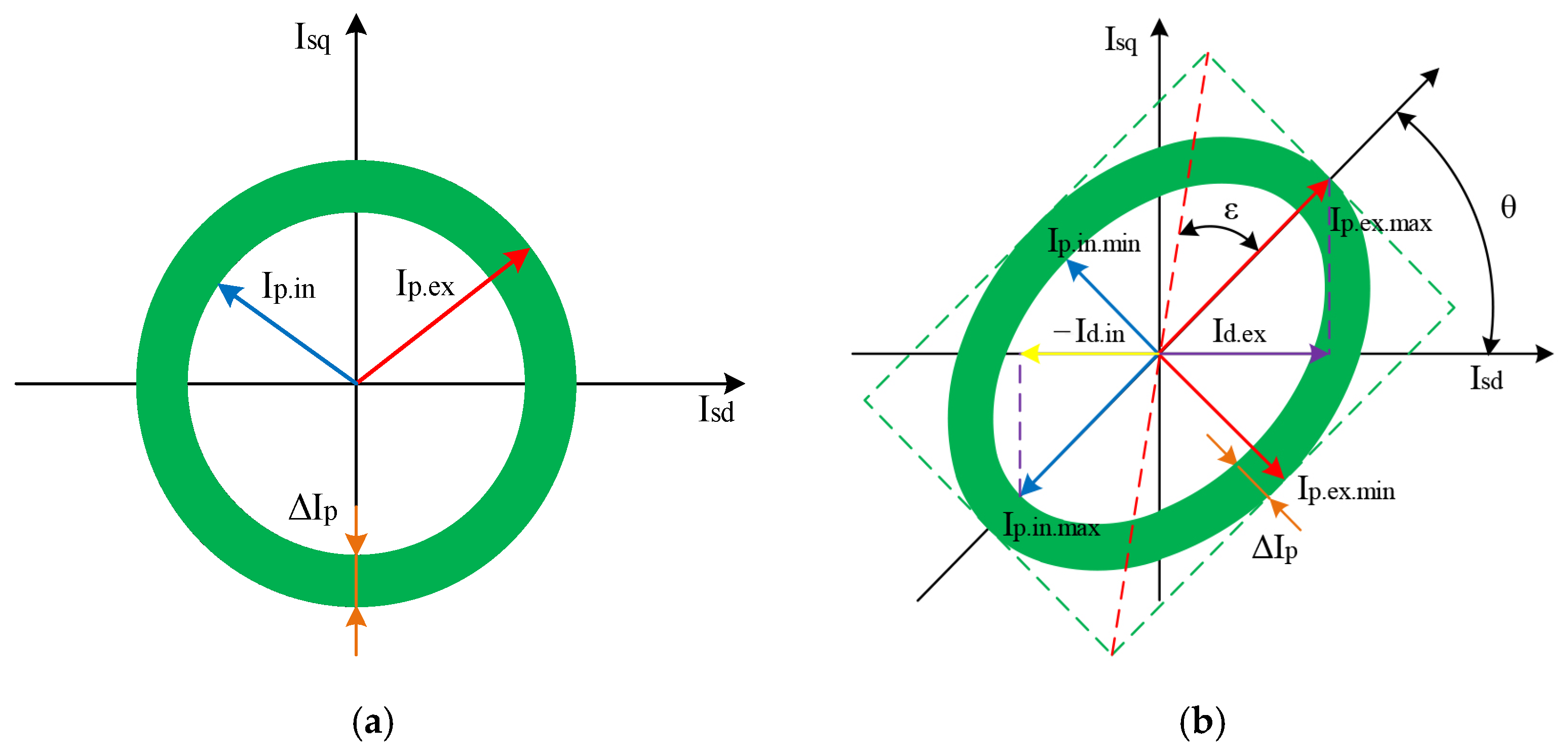
As can be seen from Figure 3a, with a symmetrical system of the power supply voltages of an induction motor, the hodograph of the Park’s vector describes a circle, and the thickening of the Park’s vector line means that there is damage in the rotor. It is possible to determine the presence of rotor damage by calculating the thickness of the Park’s vector line. According to the conducted simulation, when the supply voltage system is not symmetrical, the trajectory of the Park’s vector describes an ellipse even with symmetrical stator windings and an intact rotor. The effect of rotor damage for an unbalanced power system on the Park’s vector pattern is also observed. If the rotor is not damaged, the ellipse will be described by a thin line, and if the rotor is damaged, the line of the ellipse will thicken. In addition to the creation of an ellipse, when the symmetry of the supply voltage is violated, the slope of the ellipse is created with an angle that depends on the degree of asymmetry of the supply voltages, which also affects the accuracy of the calculation of the thickness of the Park’s vector pattern. To determine the thickness of the ellipse line—which depends on the accuracy of quantifying the degree of damage—in the presence of asymmetry in the supply voltage system, the trajectory of the Park’s vector should be transferred from an orthogonal elliptical basis (Figure 4b) to an orthogonal circular one (Figure 4a).
The following designations are accepted in Figure 4:
Ip.ex—Park’s vector of the external circle (Figure 4a);
Ip.in—Park’s vector of the inner circle (Figure 4a);
Ip.ex.max—the maximum value of the Park’s vector for the external circle (Figure 4b);
Ip.ex.min—the minimum value of the Park’s vector for the external circle (Figure 4b);
Ip.in.max—the maximum value of the Park’s vector for the inner circle (Figure 4b);
Ip.in.min—the minimum value of the Park’s vector for the inner circle (Figure 4b);
Id.ex—projection of the Park’s vector of the external circle onto the d-axis (Figure 4b);
Id.in—projection of the Park’s vector of the inner circle onto the d-axis (Figure 4b);
ε—angle of ellipticity;
θ—angle of inclination of the ellipse.
To determine the degree of damage to the rotor with a symmetrical power system (see Figure 4a), the thickness of the circle line of the Park’s vector is calculated according to the formula:
Δ I p = I p . e x I p . i n ,
where:
Ip.ex—Park’s vector of the external circle;
Ip.in—Park’s vector of the inner circle.
Since, with the symmetry of the supply voltage system, the modulus of the Park’s vector is the instantaneous value of the phase current of phase A, then expression (4) takes the following form:
Δ I p = I s A max I s A m i n ,
where:
IsAmax—the maximum instantaneous value of the stator phase current of phase A;
IsAmin—the minimum instantaneous value of the stator phase current of phase A.
A value of ΔIp = 0 will mean that the rotor is intact. A value of Δip > 0 will indicate the presence of damage in the rotor, and the larger the value of Δip, the more damaged the rotor.
When determining the thickness of the ellipse line in the presence of asymmetry in the supply voltage system, the calculation is performed in the following sequence to convert the Park’s vector pattern from an orthogonal elliptical basis (Figure 4b) to an orthogonal-circular one (Figure 4a).
Transition from three-phase to two-phase dq coordinate system according to formulae:
{ I s d = I s A cos ( ω t + φ ) 1 3 I s B s i n ( ω t + φ ) 1 3 I s C s i n ( ω t + φ ) ; I s q = I s A s i n ( ω t + φ ) + 1 3 I s B cos ( ω t + φ ) 1 3 I s C cos ( ω t + φ ) ,
where:
IsA—the instantaneous value of the stator phase current of phase A;
IsB—the instantaneous value of the stator phase current of phase B;
IsC—the instantaneous value of the stator phase current of phase C;
ω—the angular frequency of the supply voltage;
φ—the phase shift between phase voltages and currents.
Formula (6) determines the maximum and minimum values of the Park’s vector Ipmax and Ipmin, respectively. The value with the max index corresponds to the Park’s vector of the outer circle, and the value with the min index corresponds to the Park’s vector of the inner circle.
When projecting the obtained maximum value of the outer circle of the Park’s vector Ipmax onto the d-axis, Id.ex is determined. Based on the values of the Park’s vector for the outer circle Ipmax and its projection on the d-axis Id.ex, the angle of inclination of the ellipse of the drawing of the Park’s vector is determined (see Figure 4b):
θ = arccos i d . e x i p max .
Since the ellipses of the external and inner circles have the same angles of inclination (Figure 4b), it is not necessary to determine the angle of inclination for the inner circle.
Then, the transition from an orthogonal elliptical basis (see Figure 4b) to an orthogonal circular one (see Figure 4a) can be carried out using the formulae:
i d 0 e x = ( cos ε 0 cos θ 0 j sin ε 0 sin θ 0 ) I p m a x cos θ + j ( cos ε 0 sin θ 0 j sin ε 0 cos θ 0 ) I p m a x sin θ ,
i q 0 e x = ( cos ( ε 0 ) cos ( θ 0 + π 2 ) j sin ( ε 0 ) ( θ 0 + π 2 ) ) I p m a x cos θ + + j ( cos ( ε 0 ) sin ( θ 0 + π 2 ) j sin ( ε 0 ) cos ( θ 0 + π 2 ) ) I p m a x sin θ ,
where ε0—the angle of ellipticity of the basic single vector along the d-axis in the new basis (along the q-axis, the value of this angle is ε0. For an orthogonal-circular basis ε0 = π/4); θ0—the angle of inclination of the basic single vector ellipse along the d-axis in the new basis (along the q-axis, the value of this angle is equal to θ0 + π/2). For an orthogonal-circular basis θ0 = 0.
The maximum value of the Park’s vector for the inner circle is determined by the expression (Figure 4b):
I p . i n . max = I d . i n cos θ = I p min cos θ sin θ .
Substitution of expression (10) in (8) and (9) gives the following results:
i d 0 i n = ( cos ε 0 cos θ 0 j sin ε 0 sin θ 0 ) i p min sin θ cos θ + j ( cos ε 0 sin θ 0 j sin ε 0 cos θ 0 ) i p m a x i p m i n cos θ ,
i q 0 i n = ( cos ( ε 0 ) cos ( θ 0 + π 2 ) j sin ( ε 0 ) ( θ 0 + π 2 ) ) i p min sin θ + + j ( cos ( ε 0 ) sin ( θ 0 + π 2 ) j sin ( ε 0 ) cos ( θ 0 + π 2 ) ) i p m i n cos θ .
Then, the projections of the Park’s vector of the external circle in the new basis can be defined as:
{ i d 0 e x = ( Re ( i d 0 e x ) ) 2 + ( Im ( i d 0 e x ) ) 2 ; i q 0 e x = ( Re ( i d 0 e x ) ) 2 + ( Im ( i d 0 e x ) ) 2 .
Projections of the Park’s vector of the inner circle in the new basis are defined as:
{ i d 0 i n = ( Re ( i d 0 i n ) ) 2 + ( Im ( i d 0 i n ) ) 2 ; i q 0 i n = ( Re ( i d 0 i n ) ) 2 + ( Im ( i d 0 i n ) ) 2 .
If I′d0ex = I′q0ex and I′d0in = I′q0in are equal, and if I′d0ex≠I′d0in and I′q0ex≠I′q0in, there will be damage in the rotor of the induction motor. When I′d0ex≠I′q0ex and I′d0in≠I′q0in and I I′d0ex≠I′d0in and I′q0ex≠I′q0in, damage will occur in both the stator and the rotor. If I′d0ex≠I′q0ex and I′ I′d0in≠I′q0in and I′d0ex = I′d0in and I′q0ex = I′q0in, damage will occur only in the stator [21].
Since it was found that when only the rotor of the induction motor is damaged, I′d0ex = I′q0ex and I′d0in = I′q0in, the thickness of the Park’s vector line can be calculated using the expression:
Δ i p = i d 0 e x i d 0 i n ,
or by expression:
Δ i p = i q 0 e x i q 0 i n .
Calculation of the figure thickness of the Park’s vector according to expressions (15) and (16) according to the proposed method allows us to obtain the value of ∆Ip, which can be used to quantitatively assess the degree of damage to the rotor winding of an induction electric machine with a sufficiently high reliability, regardless of the quality of the power supply system.

3.3. Algorithm for Using Park’s Method for Rotor Diagnostics in Built-In Diagnostic Systems

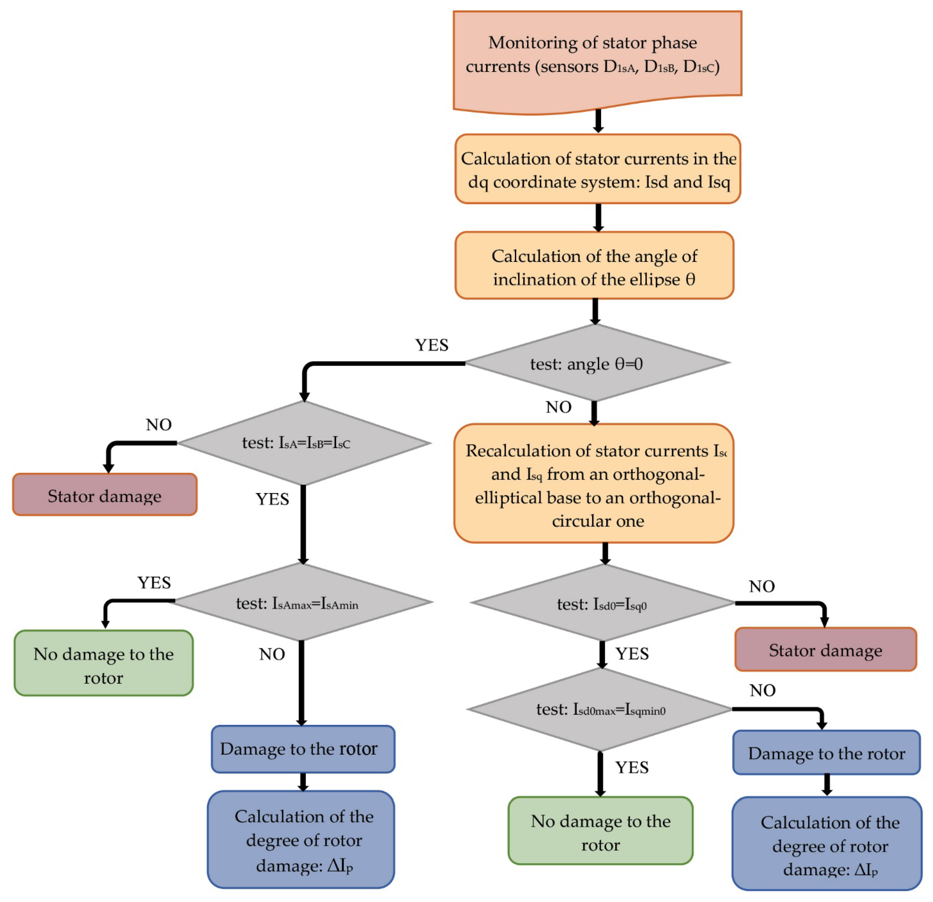
In accordance with the proposed method of calculating the thickness of the Park’s vector figure, an algorithm for diagnosing damage to the rotor of an induction motor in the built-in vehicle diagnostics system has been developed. When compiling the algorithm, we considered the option of sharing the same sensors for the stator interturn diagnostic module and determining the state of the rotor using the Park’s vector method.The algorithm for diagnosing damage to the rotor of an induction motor for practical implementation is shown in Figure 5.
To obtain the value of the phase currents, three current sensors—DIsA, DIsB, and DIsC—are used. It is typical for transport systems that an induction electric motor receives power from an autonomous voltage inverter, so the supply voltage system can be non-sinusoidal in nature. Therefore, to determine the amplitude and phase of the first (fundamental) harmonic of the stator phase currents (IsA1, IsB1, IsC1, φIsA1, φIsB1, φI), a fast Fourier transform block is used to correctly obtain the stator current diagrams.
The amplitudes of the first harmonics of the stator phase currents (IsA1, IsB1, IsC1) are sent to the block where they are converted from the three-phase coordinate system to the two-phase moving dq coordinate system with the receipt of Isd and Isq currents in accordance with (5). After determining Ipmax and its projection on the d-axis (Id.ex), the angle of inclination of the ellipse of the drawing of the Park’s vector from (6) is determined. If the angle is θ = 0 , then the induction motor has a symmetrical quality supply, and the stator currents are used to determine the damage element of the motor. In case of damage to the rotor winding, the difference between the maximum instantaneous phase current of the stator IsAmax and the minimum instantaneous phase current IsAmin gives the value of the parameter ∆Ip (5), which determines the degree of damage to the rotor.
At the set value of the angle of inclination of the shape of the trajectory of the Park’s vector (Figure 4b), the electric machine receives low-quality power; therefore, in order to accurately determine the parameter ∆Ip, it is necessary to recalculate the current values Isd and Isq for the transition from the orthogonal elliptical basis to the orthogonal circular basis according to the ratios (7)–(11).
After determining the values of the projections of the stator currents of the Park’s vector figure on the d-axis (Isd0) and on the q-axis (Isq0), the damaged machine element is set. If the values of current projections are uneven, the stator winding of the machine is damaged. In the case of the Isd0=Isq0 equation, the maximum instantaneous value of the phase current projection Isd0max and the minimum instantaneous value of the stator phase current projection Isd0min are compared. When the values of the current projections differ, the parameter ∆Ip is calculated, which can be called the “rotor damage criterion” in the future. An increase in the ∆Ip parameter indicates an increase in the level of damage to the squirrel-cage rotor winding, the development of which can be monitored during the operation of the electric machine.

4. Discussion

The Park’s vector hodograph method is the most promising method for monitoring the state of the main elements of an induction motor during operation using the automation of the diagnostic process. The advantage of the method is the ability to obtain reliable diagnostic parameters despite the quality of the power supply system being disturbed at the earliest stages of their appearance. In the proposed rotor condition control algorithm, it is possible to establish the current technical condition of the rotor by comparing the width of the ring of the Park’s vector circle with the reference value for this type of engine and to control the development of the degree of damage to the rotor by increasing the width of the ring of the Park’s vector figure. To control the development of rotor defects during the operation of the electric machine, the damage criterion ∆Ip is used. When powering the machine through an inverter with a non-sinusoidal signal, the algorithm provides for the use of a fast Fourier transform block to determine the amplitude and phase of the first (main) harmonic of the phase currents to obtain correct diagnostic results. The main disadvantage of using Park’s method in diagnostics is the difficulty of detecting damage in idling modes or with a slight engine load. However, for the use of the method in the built-in diagnostic systems of vehicles, this is not decisive. In order to identify the degree of severity of damage to the squirrel-cage rotor winding and to determine the number of damaged rods based on the value of the parameter ∆Ip, it is necessary to conduct additional research by means of mathematical modeling. At the same time, already at this stage, it is possible to predict the period of trouble-free operation of the engine based on the deviation of the value of ∆Ip. In addition, when using Park’s method, some current sensors and a part of the calculation blocks are used to determine the state of the stator winding to ensure the diagnostic processes of both important engine elements.
The use of Park’s vector method is also possible for the detection of mechanical damage, which demonstrates the universality and perspective of the method for use in the built-in diagnostic monitoring systems of all important elements of an induction motor.
The next work will be devoted to research on determining the number of damaged rotor winding rods via the proposed method. This is necessary for making a prognosis of trouble-free operation during the period of operation of the electric machines of vehicles and planning the recovery period in the event of damage.

5. Conclusions

The work provides statistics of damage to the main important elements of induction electric machines that are subject to control during the period of operation to ensure the efficiency and safety of transportation. Research on the development of a methodology and algorithm for the practical application of Park’s vector approach for diagnosing rotor damage during engine operation is also presented.
In the course of research, a procedure was developed for recalculating the values of the amplitudes of the phase currents of the stator—obtained with a poor-quality power supply system—to the actual values of the currents of the symmetrical system of the supply voltages of the induction motor in order to correctly determine the degree of damage to the rotor.
A means of determining the thickness of the circle of the trajectory of the Park’s vector is proposed for determining the degree of rotor damage by the difference between the maximum and minimum values of the phase currents of the Park’s vector pattern, which correspond to the outer and inner size of the circle of the vector trajectory.
The algorithm of the module for monitoring the presence of damage in the squirrel-cage rotor winding has been developed for practical implementation in diagnostic systems with possible use together with the module for monitoring the stator from common sensors and part of the blocks.
The proposed control approach allows us to determine the degree of damage to the squirrel-cage rotor winding and to monitor the development of the defect during operation using an automated mode, regardless of the quality of the power supply system.

Author Contributions

Conceptualization, O.G. and O.K.; methodology, O.G., O.K. and J.G.; software, O.G. and I.M.; validation, O.G. and I.M.; formal analysis, O.K., I.M. and O.M.; investigation, O.G., O.K. and I.M.; resources, O.G., I.M. and O.M.; writing—original draft preparation, O.G. and O.K.; writing—review and editing, J.G. and O.K.; visualization, O.G., O.K. and I.M.; supervision, O.G. and J.G. All authors have read and agreed to the published version of the manuscript.

Funding

This publication was issued thanks to support from the Cultural and Educational Grant Agency of the Ministry of Education of the Slovak Republic in the projects, “Implementation of modern methods of computer and experimental analysis of properties of vehicle components in the education of future vehicle designers” (Project No. KEGA 036ŽU-4/2021). This research was also supported by the Slovak Research and Development Agency of the Ministry of Education, Science, Research and Sport of the Slovak Republic in Educational Grant Agency of the Ministry of Education of the Slovak Republic in the project and VEGA 1/0513/22 “Investigation of the properties of railway brake components in simulated operating conditions on a flywheel brake stand” and project “Scholarships for Excellent Researchers Threatened by the Military Conflict in Ukraine”, code 09103-03-V01-00129.

Data Availability Statement

Not applicable.

Conflicts of Interest

The authors declare no conflict of interest.

References

  1. Tuychieva, M. Control of electric locomotives with asynchronous electric motors under asymmetric operating conditions in Uzbekistan. IOP Conf. Ser. Earth Environ. Sci. 2020, 614, 012060. [Google Scholar] [CrossRef]
  2. Lovska, A.; Fomin, O.; Píštěk, V.; Kučera, P. Dynamic load modelling within combined transport trains during transportation on a railway ferry. Appl. Sci. 2020, 10, 5710. [Google Scholar] [CrossRef]
  3. Kuznetsov, V.; Kardas-Cinal, E.; Gołębiowski, P.; Liubarskyi, B.; Gasanov, M.; Riabov, I.I.; Kondratieva, L.; Opala, M. Method of Selecting Energy-Efficient Parameters of an Electric Asynchronous Traction Motor for Diesel Shunting Locomotives—Case Study on the Example of a Locomotive Series ChME3 (ЧMЭ3, ČME3, ČKD S200). Energies 2022, 15, 317. [Google Scholar] [CrossRef]
  4. Goolak, S.; Tkachenko, V.; Šťastniak, P.; Sapronova, S.; Liubarskyi, B. Analysis of Control Methods for the Traction Drive of an Alternating Current Electric Locomotive. Symmetry 2022, 14, 150. [Google Scholar] [CrossRef]
  5. Balakrishna, P.; Khan, U. An Autonomous Electrical Signature Analysis-Based Method for Faults Monitoring in Industrial Motors. IEEE Trans. Instrum. Meas. 2021, 70, 1–8. [Google Scholar] [CrossRef]
  6. Wu, Y.; Jiang, B.; Wang, Y. Incipient winding fault detection and diagnosis for squirrel-cage induction motors equipped on CRH trains. ISA Trans. 2020, 99, 488–495. [Google Scholar] [CrossRef] [PubMed]
  7. Kondratieva, L.; Bogdanovs, A.; Overianova, L.; Riabov, I.; Goolak, S. Determination of the Working Energy Capacity of the On-Board Energy Storage System of an Electric Locomotive for Quarry Railway Transport During Working with a Limitation of Consumed Power. Arch. Transp. 2023, 65, 119–135. [Google Scholar] [CrossRef]
  8. Turpak, S.M.; Taran, I.O.; Fomin, O.V.; Tretiak, O.O. Logistic technology to deliver raw material for metallurgical production. Sci. Bull. Natl. Min. Univ. 2018, 1, 162–169. [Google Scholar] [CrossRef]
  9. Bodnar, B.; Ochkаsov, O.; Bodnar, E.; Hryshechkina, T.; Keršys, R. Safety performance analysis of the movement and operation of locomotives. In Proceedings of the Transport means 2018: 22nd International Scientific Conference, Trakai, Lithuania, 3–5 October 2018; Kaunas University of Technology: Kaunas, Lithuania, 2018. Pt. II. pp. 839–843. Available online: https://transportmeans.ktu.edu/wp-content/uploads/sites/307/2018/02/Transport-means-II-A4-2018-09-25.pdf (accessed on 25 March 2023).
  10. Gubarevych, O.; Goolak, S.; Golubieva, S. Classification of Defects, Systematization and Selection of Methods for Diagnosing the Stator Windings Insulation of Asynchronous Motors. Rev. Roum. Sci. Techn.–Électrotechn. et Énerg 2022, 67, 445–450. [Google Scholar]
  11. Choudhary, A.; Goyal, D.; Shimi, S.L.; Akula, A. Condition Monitoring and Fault Diagnosis of Induction Motors: A Review. Arch. Comput. Methods Eng. 2019, 26, 1221–1238. [Google Scholar] [CrossRef]
  12. Rauf1, A.; Usman, M.; Butt, A.; Ping, Z. Health Monitoring of Induction Motor Using Electrical Signature Analysis. J. Dong Hua Univ. 2022, 39, 265–271. [Google Scholar] [CrossRef]
  13. Gundewar, S.K.; Kane, P.V. Condition Monitoring and Fault Diagnosis of Induction Motor. J. Vib. Eng. Technol. 2021, 9, 643–674. [Google Scholar] [CrossRef]
  14. Gubarevych, O.; Gerlici, J.; Gorobchenko, O.; Kravchenko, K.; Zaika, D. Analysis of the features of application of vibration diagnostic methods of induction motors of transportation infrastructure using mathematical modeling. Diagnostyka 2023, 24, 2023111. [Google Scholar] [CrossRef]
  15. AlShorman, O.; Alkahatni, F.; Masadeh, M.; Irfan, M.; Glowacz, A.; Althobiani, F.; Kozik, J.; Glowacz, W. Sounds and acoustic emission-based early fault diagnosis of induction motor. A review study. Adv. Mech. Eng. 2021, 13, 1–19. [Google Scholar] [CrossRef]
  16. Yatsugi, K.; Pandarakone, S.E.; Mizuno, Y.; Nakamura, H. Common Diagnosis Approach to Three-Class Induction Motor Faults Using Stator Current Feature and Support Vector Machine. IEEE Access 2023, 11, 24945–24952. [Google Scholar] [CrossRef]
  17. Abdelhak, G.; Sid Ahmed, B.; Djekidel, R. Fault diagnosis of induction motors rotor using current signature with different signal processing techniques. Diagnostyka 2022, 23, 2022201. [Google Scholar] [CrossRef]
  18. Wei, L.; Rong, X.; Wang, H.; Yu, S.; Zhang, Y. Method for Identifying Stator and Rotor Faults of Induction Motors Based on Machine Vision. Math. Probl. Eng. 2021, 2021, 6658648. [Google Scholar] [CrossRef]
  19. Vilhekar, T.G.; Ballal, M.S.; Suryawanshi, H.M. Application of Multiple Parks Vector Approach for Detection of Multiple Faults in Induction Motors. J. Power Electron. 2017, 17, 972–982. [Google Scholar] [CrossRef]
  20. Wei, S.; Zhang, X.; Xu, Y.; Fu, Y.; Ren, Z.; Li, F. Extended Park’s vector method in early inter-turn short circuit fault detection for the stator windings of offshore wind doubly-fed induction generators. IET Gener. Transm. Distrib. 2020, 14, 3905–3912. [Google Scholar] [CrossRef]
  21. Gerlici, J.; Goolak, S.; Gubarevych, O.; Kravchenko, K.; Kamchatna-Stepanova, K.; Toropov, A. Method for Determining the Degree of Damage to the Stator Windings of an Induction Electric Motor with an Asymmetric Power System. Symmetry 2022, 14, 1305. [Google Scholar] [CrossRef]
  22. Sheikh, M.A.; Bakhsh, S.T.; Irfan, M.; bin Mohd Nor, N.; Nowakowski, G. A Review to Diagnose Faults Related to Three-Phase Industrial Induction Motors. J. Fail. Anal. Prev. 2022, 22, 1546–1557. [Google Scholar] [CrossRef]
  23. Gubarevych, O.; Goolak, S.; Melkonova, I.; Yurchenko, M. Structural diagram of the built-in diagnostic system for electric drives of vehicles. Diagnostyka 2022, 23, 2022406. [Google Scholar] [CrossRef]
  24. Sarkar, S.; Das, S.; Purkait, P. Wavelet and SFAM based classification of induction motor stator winding short circuit faults and incipient insulation failures. In Proceedings of the IEEE 1st International Conference on Condition Assessment Techniques in Electrical Systems (CATCON), Kolkata, India, 6–8 December 2013; pp. 237–242. Available online: http://toc.proceedings.com/21152webtoc.pdf (accessed on 25 March 2023).
  25. Spyropoulos, D.V.; Mitronikas, E.D. Induction motor stator fault diagnosis technique using Park vector approach and complex wavelets. In Proceedings of the 2012 XXth International Conference on Electrical Machines, Marseille, France, 2–5 September 2012; pp. 1730–1734. [Google Scholar]
  26. Gyftakis, K.N.; Cardoso, A.J.M.; Antonino-Daviu, J.A. Introducing the Filtered Park’s and Filtered Extended Park’s Vector Approach to detect broken rotor bars in induction motors independently from the rotor slots number. Mech. Syst. Signal Process. 2017, 93, 30–50. [Google Scholar] [CrossRef]
  27. Goolak, S.; Riabov, I.; Tkachenko, V.; Kondratieva, L. Concerning the Diagnosis of Asymmetric Modes in the Traction Induction Drive of the Electric Locomotive. In Proceedings of the 2022 IEEE 3rd KhPI Week on Advanced Technology (KhPIWeek), Kharkiv, Ukraine, 3–7 October 2022; pp. 1–6. [Google Scholar]
  28. Chaouch, A.; Chouitek, M.; Mohamed Reda, M.A.; Belaid, M. Current Park’s Vector Pattern Technique for Diagnosis of Broken Rotor Bars Fault in Saturated Induction Motor. J. Electr. Eng. Technol. 2023. [Google Scholar] [CrossRef]
  29. Messaoudi, M.; Flah, A.; Alotaibi, A.A.; Althobaiti, A.; Sbita, L.; El-Bayeh, C.Z. Diagnosis and fault detection of rotor bars in squirrel cage induction motors using combined Park’s vector and extended Park’s vector approaches. Electronics 2022, 11, 380. [Google Scholar] [CrossRef]
  30. Goolak, S.; Riabov, I.; Gorobchenko, O.; Yurchenko, V.; Nezlina, O. Improvement of the model of an asynchronous traction motor of an electric locomotive by taking into account power losses. Prz. Elektrotechnicznythis 2022, 98, 1–10. [Google Scholar] [CrossRef]
  31. Gubarevych, O.; Golubieva, S.; Melkonova, I. Comparison of the results of simulation modeling of an asynchronous electric motor with the calculated electrodynamic and energy characteristics. Przegląd Elektrotechniczny 2022, 98, 61–66. [Google Scholar] [CrossRef]
Figure 1. Distribution of induction motor failures.
Energies 16 05109 g001
Figure 2. Damage to the rotor winding: (a) cast winding; (b) welded winding.
Energies 16 05109 g002
Figure 3. Hodographs of the Park’s vector with a symmetrical induction power supply system of an electric machine: (a) for an intact rotor; (b) with one damaged rod rotor.
Energies 16 05109 g003
Figure 4. The trajectory of the Park’s vector with a damaged rotor: (a) with a symmetrical power system; (b) with an asymmetric power system.
Energies 16 05109 g004
Figure 5. Algorithm for diagnosing damage to the rotor of an induction motor.
Energies 16 05109 g005
Disclaimer/Publisher’s Note: The statements, opinions and data contained in all publications are solely those of the individual author(s) and contributor(s) and not of MDPI and/or the editor(s). MDPI and/or the editor(s) disclaim responsibility for any injury to people or property resulting from any ideas, methods, instructions or products referred to in the content.