Article

High Brightness Ce:Nd:YAG Solar Laser Pumping Approach with 22.9 W/m2 TEM00-Mode Collection Efficiency

CEFITEC, Departamento de Física, FCT, Universidade NOVA de Lisboa, Campus de Caparica, 2829-516 Caparica, Portugal
*
Author to whom correspondence should be addressed.
Energies 2023, 16(13), 5143; https://doi.org/10.3390/en16135143
Submission received: 28 April 2023 / Revised: 29 May 2023 / Accepted: 26 June 2023 / Published: 3 July 2023
(This article belongs to the Special Issue Challenge and Research Trends of Solar Concentrators II)

Abstract

:
A compact side-pumped solar laser design using a Ce:Nd:YAG laser medium is here proposed to improve the TEM00-mode solar laser output performance, more specifically the beam brightness. The solar laser performance of the Ce:Nd:YAG laser head was numerically studied by both ZEMAX® v13 and LASCADTM v1 software. Maximum multimode laser power of 99.5 W was computed for the 4.1 mm diameter, 34 mm length grooved rod, corresponding to a collection efficiency of 33.2 W/m2. To extract TEM00-mode solar laser, symmetric and asymmetric optical resonators were investigated. For the 4.1 mm diameter, 34 mm length grooved rod, maximum TEM00-mode solar laser collection efficiency of 22.9 W/m2 and brightness figure of merit of 62.4 W were computed using the symmetric optical resonator. While, for the asymmetric optical resonator, the maximum fundamental mode solar laser collection efficiency of 16.1 W/m2 and brightness figure of merit of 37.3 W were numerically achieved. The asymmetric resonator offered a TEM00-mode laser power lower than the one obtained using the symmetric resonator; however, a collimated laser beam was extracted from the asymmetric resonator, unlike the divergent TEM00-mode laser beam provided by the symmetric resonator. Nevertheless, using both optical resonators, the TEM00-mode Ce:Nd:YAG solar laser power and beam brightness figure of merit were significantly higher than the numerical values obtained by the previous Nd:YAG solar laser considering the same primary concentrator.

1. Introduction

Solar-pumped lasers (SPLs) are of burgeoning significance attributable to the ability to directly convert part of the solar emission spectrum into narrowband, coherent and collimated laser radiation. Several prospective applications are envisaged, such as laser-enabled space connectivity, wireless power transfer from space, laser power beaming, and high-temperature materials processing [1,2,3]. In comparison with electrically powered laser, SPL offers simplicity, reliability and low cost due to electricity conversion and regulation systems being unneeded.
The first laser emission pumped by solar radiation dates from the 1960s [4,5]. Since then, great progresses in optical pumping systems and laser media have taken place to ameliorate the SPL performance [6,7,8,9,10,11,12,13,14,15,16,17,18,19].
Although the yttrium aluminum garnet (YAG) doped with neodymium (Nd) ions single rod is the laser medium usually employed in SPLs as a result of its high conversion yield for absorbed photons, efficient heat transfer properties, and mechanical strength, it is not very efficient at absorbing broadband solar radiation, which limits its ability to transform solar radiation into a laser. The utilization of sensitizers (Cr3+ and Ce3+ or both) to co-dope the Nd:YAG crystal could lead to an efficiency increase by radiative and non-radiative energy transfer between the co-doped ions and Nd3+ ions [20]. SPLs have used Cr:Nd:YAG active media, presenting results in concordance with the theoretical prediction [14,16,21].
The Ce:Nd:YAG active media have revealed a large capability to improve the broadband-pumped laser performance, compared with the Nd:YAG media [19,22,23,24,25]. Within the range of ultraviolet and visible wavelengths, the absorption of pump light is strong for Ce:Nd:YAG medium and the energy transfer from Ce3+ to Nd3+ ions is efficient. Figure 1 illustrates the standard solar emission spectrum as well as the fluorescence and absorption spectra of Ce:YAG and Ce:Nd:YAG, respectively. The Ce:YAG fluorescence shows an intense, wide green emission centered at approximately 530 nm, which matches well with two Nd3+ ion peaks of maximum absorption at around 530 nm and 589 nm. In contrast, the Ce:Nd:YAG absorption spectrum features two wide spectral regions of absorption centered at 460 nm and 340 nm, resulting from the Ce3+ ion in the YAG lattice, while other absorption zones are attributed to the Nd3+ ions.
Better heat dissipation and reduction in thermal lens effects can be achieved through grooved rods rather than conventional rods with smooth sidewalls, since the area of contact between the laser medium and the cooling water is increased due to the shape of its sidewall, further improving the laser efficiency and beam quality [12].
The TEM00-mode is one of the most preferred laser beam modes owing to the smooth intensity profile and low divergence, being a beam with minimal diffraction. The first SPL operating in the fundamental mode was conducted in 2013, by the side-pumping of a Nd:YAG rod [11]. The most efficient fundamental-mode SPL achieved a collection efficiency of 7.9 W/m2 [14]. This was possible by using an end-side-pumping configuration. However, this approach seriously limits the ability to compensate for solar tracking errors because a slight deviation of the focal spot leads to a misalignment of the pump radiation with the active medium. This issue is even more critical when using thin laser rods.
Here, a compact Ce:Nd:YAG SPL system is presented to ameliorate the emission of the fundamental-mode SPL. The Ce:Nd:YAG solar laser displayed a substantial improvement in power and beam brightness figure of merit when compared to previous Nd:YAG SPLs considering the same primary concentrator [27].

2. Ce:Nd:YAG SPL

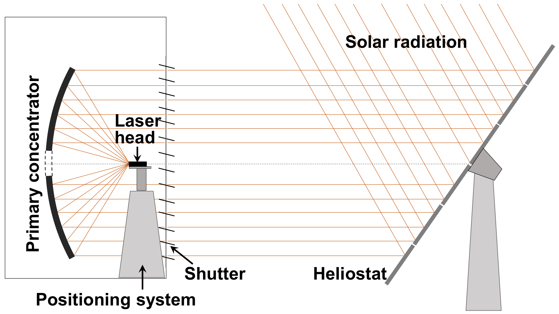
2.1. Heliostat-Parabolic Mirror System at PROMES-CNRS for Solar Energy Collection and Concentration

The PROMES-CNRS heliostat-parabolic mirror system was used in the simulation analysis. A vast flat reflector on a two-axis heliostat redirected the solar radiation to the immobile 60° rim angle, 850 mm focal length, 2 m diameter primary concentrator (Figure 2). The effective collection area of the system was 3 m2, by discounting the positioning system shadow and the aperture at the center of the parabolic concentrator. The mirrors had a silver coating on their back surfaces. Considering a combined reflectivity of only 59% for the heliostat-parabolic mirror system and a direct solar irradiance of 1000 W/m2 in Odeillo, France, a nearly Gaussian-shaped light spot with a full width at half maximum of 10 mm and 1700 W solar power can be found at the focus.

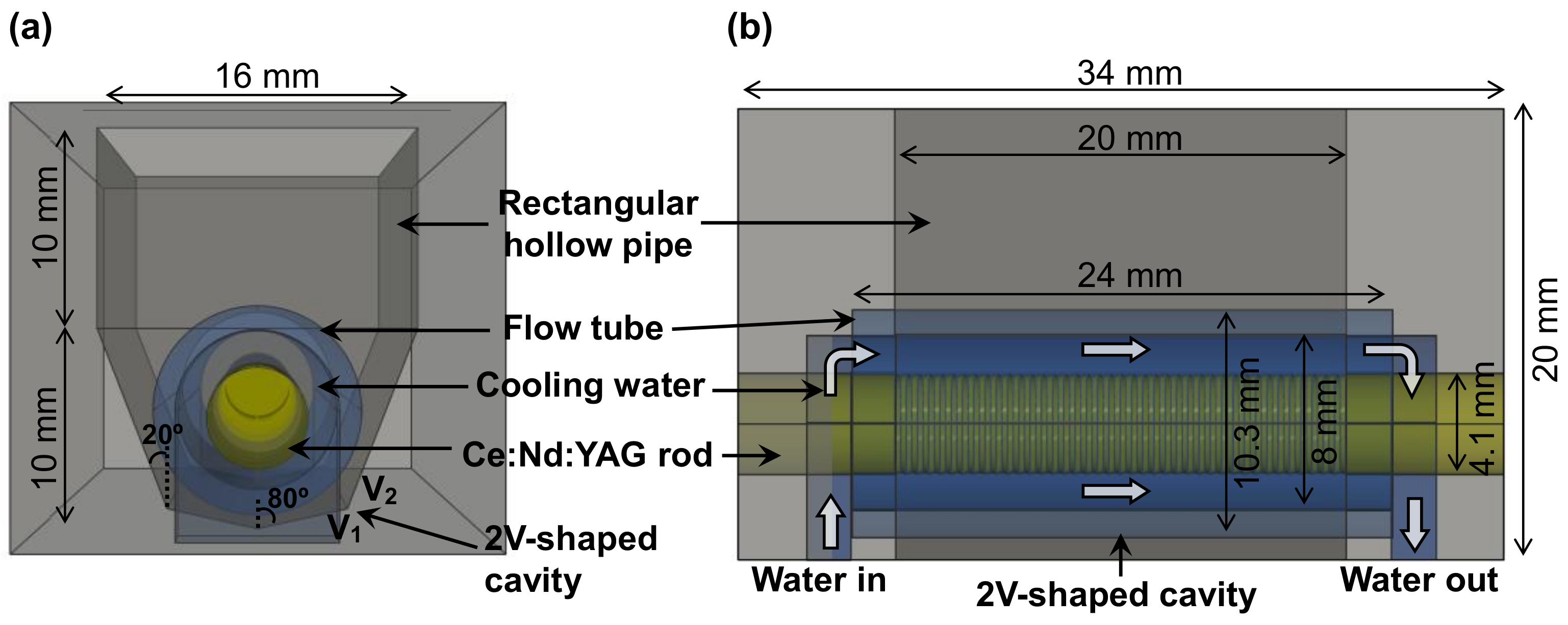
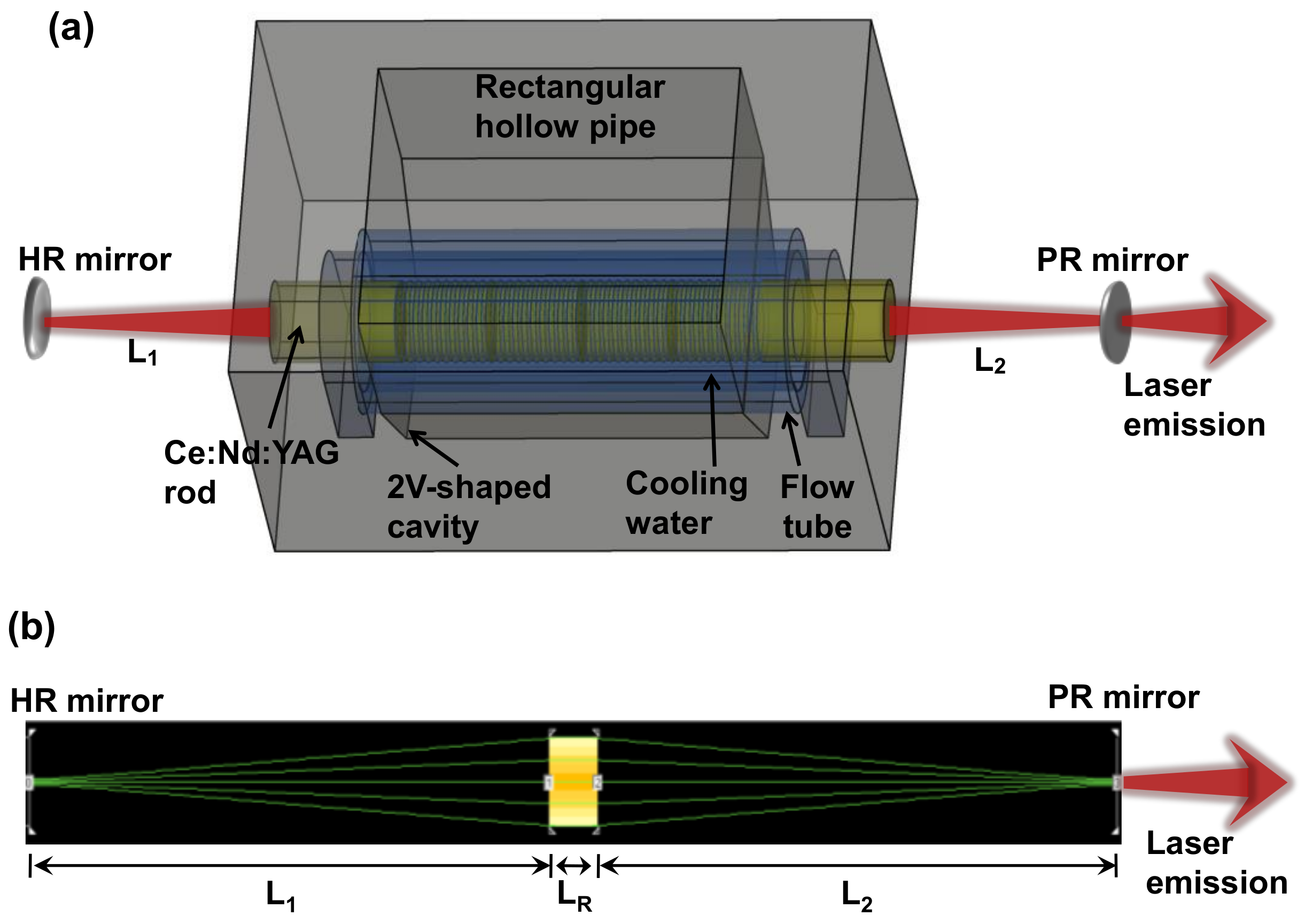
2.2. Ce:Nd:YAG Solar Laser Head

The laser head was comprised of a double-stage secondary concentrator, consisting of a rectangular hollow pipe and a 2V-shaped dry pump cavity, and a fused silica flow tube [27], within which a grooved Ce:Nd:YAG rod was placed (Figure 3).
The internal surface of the rectangular hollow pipe and the 2V-shaped dry pump cavity were considered to have 95% reflectivity, and both had a 16 mm × 20 mm entrance aperture and a 10 mm depth. A V-shaped reflector, V1, which had a half-angle of 80°, and two flat reflectors, V2, with a half-angle of 20° in relation to V1, formed the 2V-shaped cavity. This configuration ensured the efficient coupling of sun rays with different incident angles into the laser medium [27].
The laser rod was designed with a 6 mm length reserved for mechanical fixation, divided equally into 3 mm sections on either side. The remaining 28 mm of the longitudinal surface of the rod was cooled by the flow of water inside a fused silica tube. The flow tube, with an external diameter of 10.3 mm, internal diameter of 8.0 mm and length of 24 mm, also collected and concentrated the pump radiation along the laser rod.

3. Ce:Nd:YAG Solar Laser Head Numerical Optimization

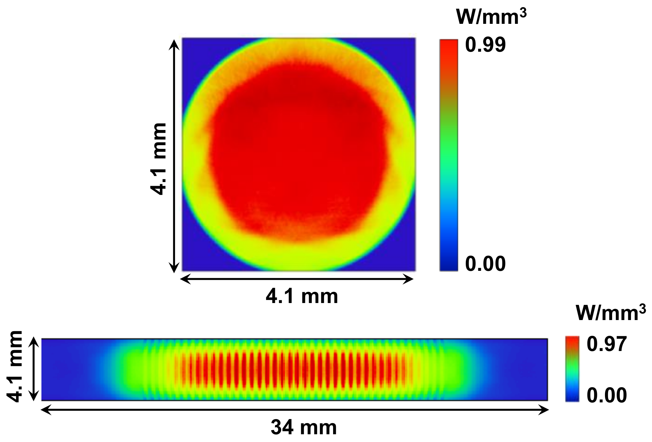
3.1. Zemax® Ray Tracing Analysis

In Figure 1, both the solar emission spectrum and the Ce:Nd:YAG absorption spectrum are shown. Nine cm−1 is the highest absorption coefficient, corresponding to the Ce3+ absorption band at 460 nm, whereas the absorption coefficient of 4.5 cm−1 corresponds to the other Ce3+ ion band located at 339 nm. The absorption coefficients of 586-nm and 531-nm Nd3+ ion peaks are 3.7 cm−1 and 2.3 cm−1, respectively, while the absorption coefficients for the peaks at 880 nm, 865 nm, 808 nm, 793 nm, 746 nm and 736 nm are 4.2 cm−1, 3.1 cm−1, 4.9 cm−1, 4.2 cm−1, 4.6 cm−1 and 5.0 cm−1, respectively.
As indicated in Equation (1), by disregarding the weak absorption lines of Nd3+, the total absorbed power ( P Nd 3 + ) per unit area can be assessed by introducing solar spectral irradiance (I λ )   in short wavelength (λ) range, firstly from λ1 = 320 nm to λ2 = 500 nm to account for the solar power absorption by Ce3+ ions, and then from λ2 = 500 nm to λ3 = 1000 nm to account for the absorption by Nd3+ ions. In the 0.1 at.% Ce3+:1.1 at.% Nd3+:YAG medium, the Ce3+ and Nd3+ ions exhibit absorption coefficients denoted by αCe (λ) and αNd (λ), respectively.
P Nd 3 +   = λ 1 λ 2 I λ   [ 1 exp   α Ce λ L   ]   η non radiative   Ce 3 + Nd 3 +   d λ   + λ 1 λ 2 I λ   [ 1 exp   α Ce λ L   ] η radiative   Ce 3 + Nd 3 +   d λ   + λ 2 λ 3 I λ   [ 1 exp   α Nd λ L   ] d λ
The first and the second integrals of Equation (1) denote the additional pathways of absorption for Nd3+ ions associated with the non-radiative and radiative energy transfer from Ce3+ to Nd3+ ions (Ce3+→Nd3+), respectively, with ηnon-radiative Ce3+―Nd3+ and ηradiative Ce3+―Nd3+ being the Ce3+→Nd3+ non-radiative and radiative energy transfer efficiencies, respectively. The direct absorption of solar radiation by Nd3+ ions is indicated in the third integral of Equation (1). The optical path length within the laser medium is represented by L.
The overlap efficiencies of the solar emission and the Nd3+ absorption spectra, and the solar emission and the Ce3+ absorption spectra of 16.0% and 15.3%, respectively, were therefore estimated, corroborating the 14–16% solar emission and Nd3+ absorption spectral overlap indicated in preceding literature [8,15].
By taking into consideration a solar irradiance of 1000 W/m2, an effective collection area of 3 m2, and an overlap between the Ce:Nd:YAG medium absorption and the AM1.5 solar emission spectra of 15.3%, an effective solar source power of 459 W was assumed for pumping the Ce3+ ions. Since non-radiative energy transfer efficiency from Ce3+ ions to Nd3+ ions of approximately 70% can occur [28], 459 W × 70% = 321.3 W source power was assigned to source 1 in ZEMAX® to calculate the absorbed pump power associated with the non-radiative Ce3+→Nd3+ transfer process.
More importantly, considering an overlap efficiency of 16% between the Nd3+ ion absorption and the solar emission spectra, an effective source power of 480 W for pumping the Nd3+ ions was added to source 1, containing 16 narrow Nd3+ ion absorption peaks centered at 880 nm, 865 nm, 820 nm, 815 nm, 808 nm, 805 nm, 803 nm, 793 nm, 790 nm, 758 nm, 753 nm, 746 nm, 743 nm, 736 nm, 732 nm, 592 nm, 586 nm, 579 nm, 569 nm, 531 nm and 527 nm. The contribution of the absorption peaks associated with source 1 was calculated from the I (λ) solar irradiance value (Figure 1).
Finally, the power contribution from source 1 was estimated to be 480.0 W + 321.3 W = 801.3 W due to the contributions of both Nd3+ absorption and Ce3+ absorption with the associated non-radiative energy transfer to Nd3+.
Besides, due to Ce3+ fluorescence efficiency of around 30% from Ce3+ to Nd3+ ions by Ce3+ fluorescence and its subsequent absorption related to the six Nd3+ absorption peaks centered at 592 nm, 586 nm, 579 nm, 569 nm, 531 nm and 527 nm [28], an effective source power of 459 W × 30% = 137.7 W was assigned to source 2 in ZEMAX®. Additionally, the weight of each absorption peak of source 2 was determined using the fluorescence irradiance value If (λ) for the corresponding peak wavelength λ.
With the aforementioned data programmed for the two sources in ZEMAX® v13 software, the optimization process of the Ce:Nd:YAG solar laser started similarly to our antecedent numerical analyses [16,25].
The design variables discussed in the previous section were optimized using ZEMAX® v13 software to attain the highest possible absorption of pump power for the Ce:Nd:YAG rod. The laser rod used in the ray-tracing simulation was 34 mm in length and 4.1 mm in diameter with 0.1 mm grooved depth and 0.6 mm grooved pitch. It was divided into 62,500 voxels. Using the effective absorption coefficients of αCe(λ) and αNd(λ) for the 0.1 at.% Ce:1.1 at.% Nd:YAG material along with the path length in each voxel, the absorbed solar pump power was calculated for each laser rod.
Figure 4 presents the spatial distribution of pump power of the grooved laser rod along the central transversal and longitudinal cross-sections. A uniform and circularly symmetric distribution of absorbed pump light within the laser medium was observed (Figure 4).

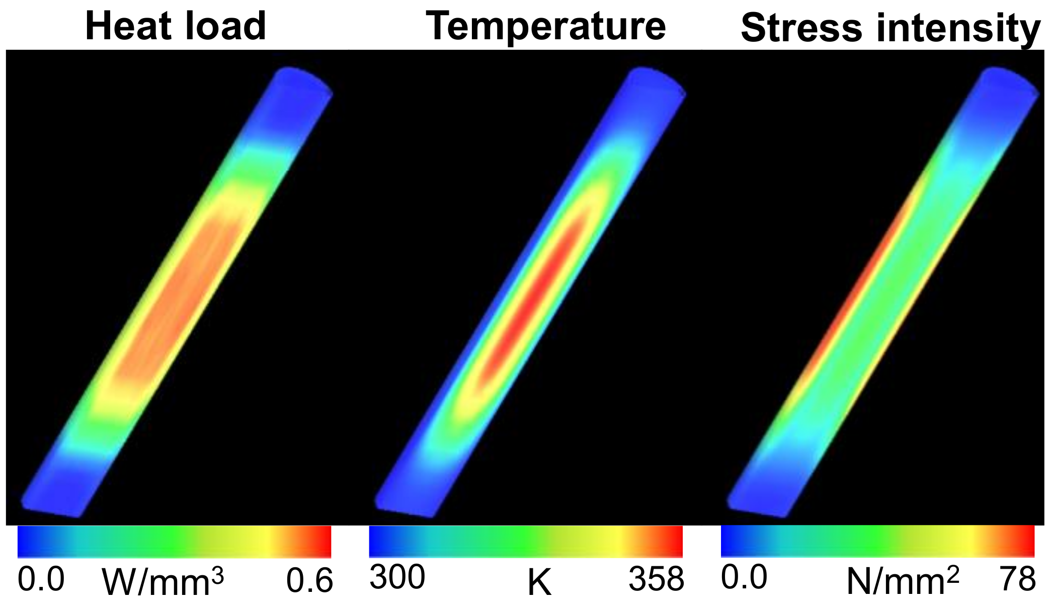
3.2. LASCADTM Analysis

The LASCADTM v1 software was utilized to optimize the resonant cavity variables and measure the thermal impact on the laser medium by processing the absorbed spatial pump power distribution data exported from the ZEMAX® software. The 660 nm solar pump wavelength was taken into account (mean absorption and intensity-weighted) along with 230 μs fluorescence lifetime, 2.8 × 10⁻¹⁹ cm2 cross-section for stimulated emission and 0.002 cm−1 absorption and scattering loss for the 0.1 at.% Ce:1.1 at.% Nd:YAG rod [8]. The laser resonator in the LASCADTM analysis was composed of two parallel mirrors that were positioned perpendicular to the laser medium’s axis, the high reflection coated (HR 1064 nm, 99.98%) rear mirror and the partial reflection coated (PR 1064 nm) output coupler with reflectivity that varied between 90% and 95%, depending on the laser rod diameter.
The loss within the resonant cavity for a complete round-trip is comprised of the combination of diffraction losses, scattering and absorption at the laser wavelength inside the active medium. Imperfect anti-reflection (AR) and HR coating losses of the resonator cavity mirrors and the laser medium additionally contributed to the total losses experienced during each round-trip within the resonant cavity. For the 4.1 mm diameter, 0.1 at.% Ce:1.1 at.% Nd:YAG rod with length LR = 34 mm, 2αLR = 1.36% amount was calculated for the scattering and absorption losses. The total loss within the resonant cavity for a complete round-trip increased to 1.76% assuming losses due to imperfect HR and AR coatings of 0.4%.

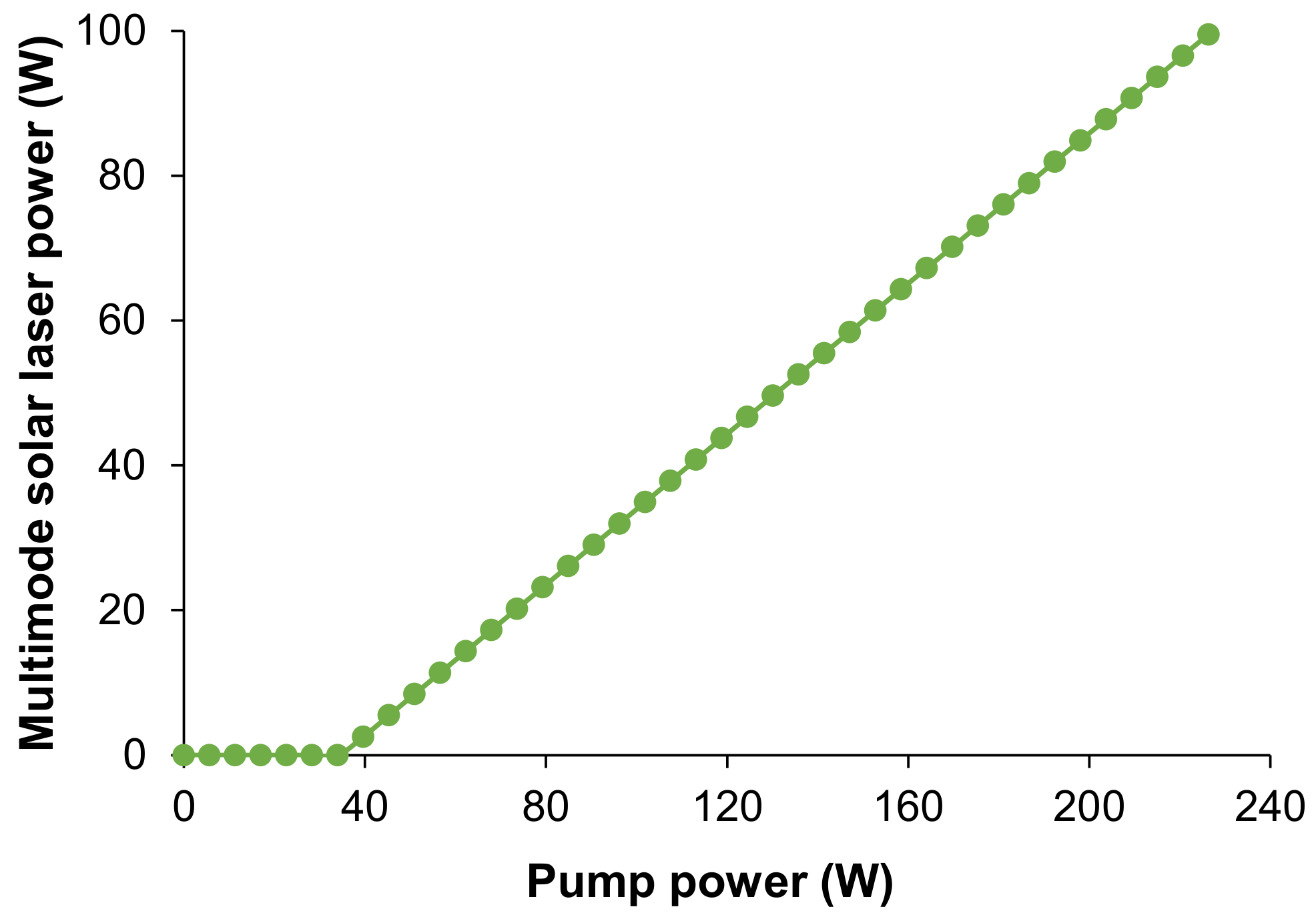
4. Multimode Solar Laser Power Analysis

A laser resonator with a symmetric configuration was used for multimode laser oscillation in LASCADTM v1 software (Figure 5). The distance between the HR mirror and the left end face of the laser rod with length LR is denoted by L1, while the separation length of the PR mirror and the laser rod’s right end face is indicated by L2. L1 = L2 = 73 mm was used as the multimode-optimized cavity length.
PR 1064 nm output mirrors and HR 1064 nm rear mirrors with different radii of curvature RoCs, and PR 1064 nm output mirrors with different reflectivities (R) were tested separately during the laser output power optimization. Different Ce:Nd:YAG rod diameters were also studied. Using RoC1 = RoC2 = 1 m for the HR 1064 nm rear mirror and the PR 1064 nm output mirror, respectively, and R = 91% for the PR 1064 nm output mirror, for the grooved Nd:YAG rod with a diameter of 4.1 mm, the beam propagation method (BPM) of LASCADTM revealed a negligible diffraction loss of 0.01%. The multimode solar laser power was found to have a 1.77% total round-trip loss. The multimode laser power for different values of absorbed pump power is presented in Figure 6. Collection efficiency of 33.2 W/m2 was attained for the 4.1 mm diameter grooved rod, which resulted from a maximum multimode laser power of 99.5 W as per the numerical simulation.
Through LASCADTM analysis, the effects induced thermically in the 4.1 mm diameter and 34 mm length grooved Ce:Nd:YAG rod were numerically calculated (Figure 7). The Ce:Nd:YAG SPL showed a safe maximum thermal stress of 78 N/mm2, maximum temperature of 358 K and maximum heat load of 0.6 W/mm3, demonstrating a good thermal performance of the side-pumped grooved Ce:Nd:YAG rod.

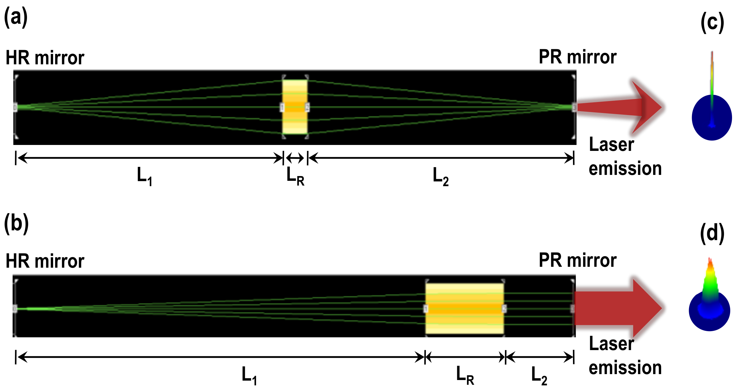
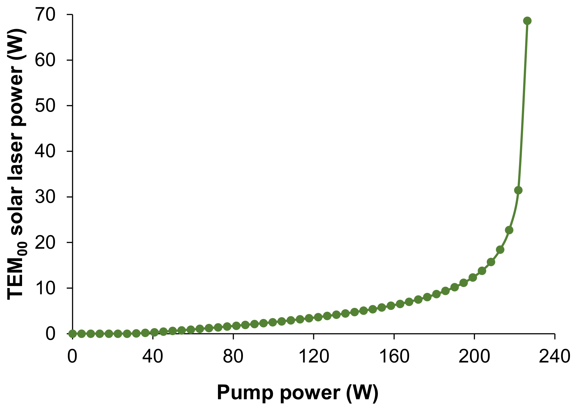
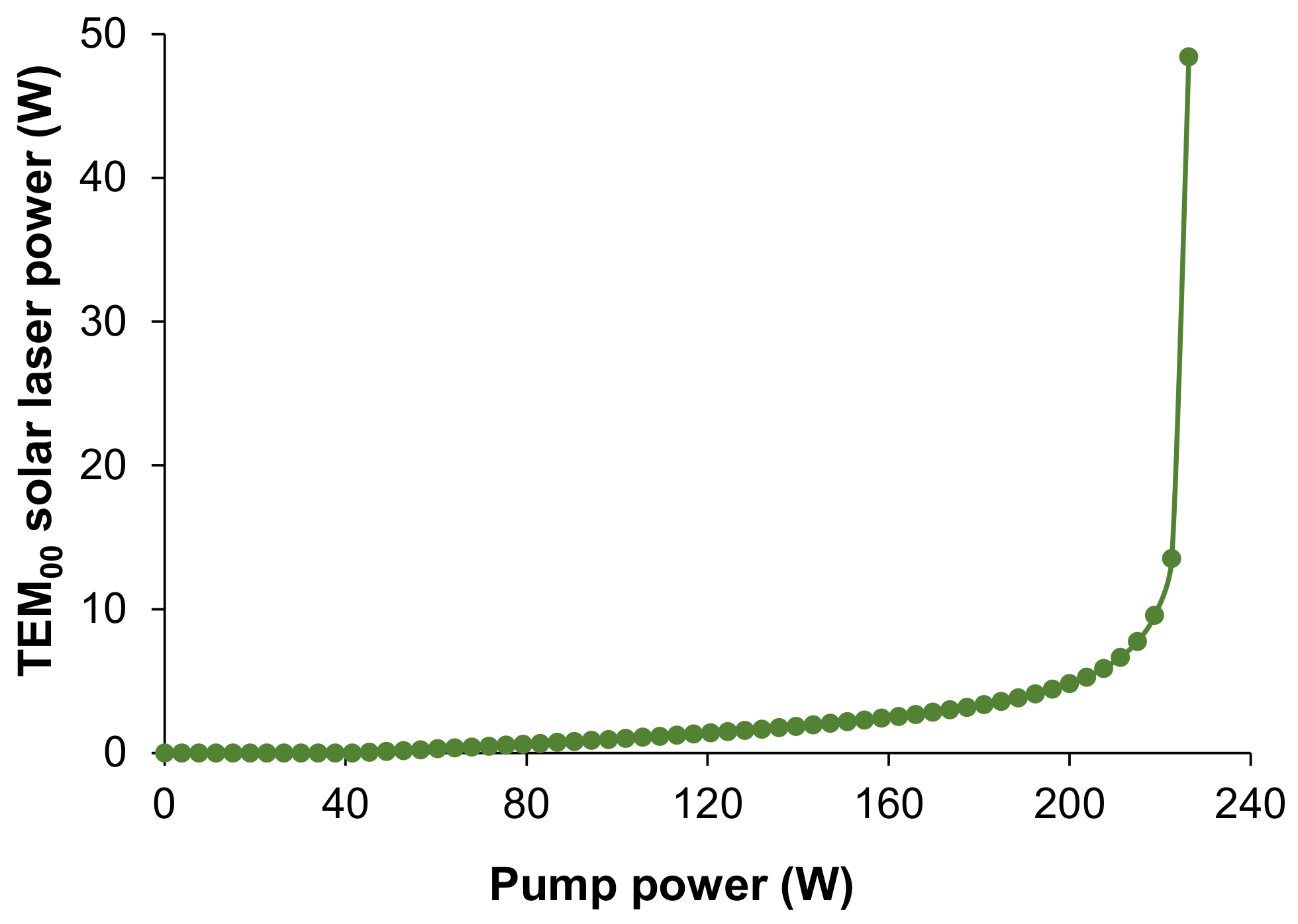
5. TEM00-Mode Solar Laser Power Analysis

For fundamental mode laser oscillation, symmetric and asymmetric optical resonators were studied in LASCADTM software (Figure 8). The parameters L1, L2, RoCs and R of the laser resonator were studied separately to optimize the TEM00-mode laser output power. Different laser rod diameters were also studied.
The symmetric optical resonator offers a significant spatial overlap between the pump and TEM00-mode volumes, enhancing the laser beam performance. An optimized cavity length of L1 = L2 = 365 mm was used in this case. The TEM00-mode solar laser power was numerically studied for different values of absorbed pump power (Figure 9). Using resonator mirrors with RoC1 = 1 m and RoC2 = ∞, and R = 92% (PR 1064 nm), maximum fundamental mode laser power of 68.6 W was computed for the grooved Ce:Nd:YAG rod with a diameter of 4.1 mm, which corresponds to a 22.9 W/m2 collection efficiency. The numerically calculated TEM00-mode solar laser power for Nd:YAG laser media pumped by the same primary parabolic concentrator [27] was surpassed by a factor of 2.14.
Using the 4.1 mm diameter grooved Nd:YAG rod, the beam quality factors were optimized, resulting in Mx2 = 1.1 and My2 = 1.0, which contributed to the excellent beam brightness figure of merit (defined as the ratio of laser power to the product of both beam quality factors Mx2, My2) of 62.4 W. This value is 1.99 higher than the highest computed brightness figure of merit obtained from the Nd:YAG SPL considering the same primary parabolic concentrator [27]. The TEM00-mode laser beam pattern is presented in Figure 8c. The output beam exhibits a Gaussian distribution with nearly minimal diffraction effects, showing around 0.2 mm 1/e2 width spot size (ω) at the output mirror.
In the asymmetric resonator configuration, L2 was fixed at 30 mm and L1 at 178 mm for a 4.1 mm diameter rod. The fundamental mode of solar laser power was numerically studied for different values of absorbed pump power, as indicated in Figure 10. Using resonator mirrors with RoC1 = ROC2 = 5 m and R = 90% for the PR 1064 nm output mirror, maximum fundamental mode power of 48.4 W was obtained by the grooved Ce:Nd:YAG rod with a diameter of 4.1 mm, which corresponds to a collection efficiency of 16.1 W/m2. Being 1.51 times higher than the highest computed Nd:YAG fundamental mode solar laser power, using the same primary concentrator [27].
Good beam quality factors Mx2 = 1.3 My2 = 1.0 were calculated, using the 4.1 mm diameter grooved Nd:YAG rod, resulting in a good solar laser beam brightness figure of merit of 37.3 W. That corresponds to 1.19 times more than the one of the Nd:YAG solar laser brightness obtained with the same primary concentrator [27]. The fundamental mode laser beam profile is presented in Figure 8d and Figure 11. The output beam exhibits a Gaussian distribution with nearly minimal diffraction effects, showing around 1.4 mm spot size 1/e2 width at the output mirror.
Using the asymmetric optical resonator, the TEM00 laser power is lower than the one obtained using the symmetric optical resonator; however, a collimated laser beam with minimal divergence is provided by the asymmetric resonator, unlike that extracted from the symmetric resonator. L1 is a critical variable to achieve the ideal modal matching. The TEM00-mode size enhances with the increase in L1, particularly for high levels of input power. Therefore, to attain a collimated beam, efficient and stable emission of fundamental mode power, the optical system should function near the boundaries of the stability region, where the TEM00-mode spot is more susceptible to thermal focal variations.

6. Conclusions

To improve the TEM00-mode solar laser output performance using the PROMES-CNRS heliostat–parabolic mirror system, a side-pumped solar laser system using the Ce:Nd:YAG laser medium was designed. The Ce:Nd:YAG solar laser head performance was numerically studied by both ZEMAX® v13 and LASCADTM v1 software. Using a symmetric and short optical resonator, maximum multimode laser power of 99.5 W was computed for the 4.1 mm diameter, 34 mm length grooved rod, corresponding to a collection efficiency of 33.2 W/m2. Symmetric and asymmetric optical resonators were investigated to extract TEM00-mode solar laser. For the 4.1 mm diameter, 34 mm length grooved rod, maximum TEM00-mode solar laser collection efficiency of 22.9 W/m2 and brightness figure of merit of 62.4 W were numerically attained using the symmetric optical resonator. While, for the asymmetric optical resonator, a maximum TEM00-mode solar laser collection efficiency of 16.1 W/m2 and a brightness figure of merit of 37.3 W was computed. The asymmetric resonator offered a TEM00-mode laser power lower than the one obtained using the symmetric resonator; however, a collimated laser beam was extracted from the asymmetric resonator, unlike the divergent TEM00-mode laser beam provided by the symmetric resonator. Nevertheless, using both optical resonators, the TEM00-mode Ce:Nd:YAG SPL power and beam brightness figure of merit were significantly higher than the numerical values reached by the previous Nd:YAG solar laser considering the same primary concentrator. In the future, the adoption of novel pumping cavity architectures, such as slab geometry laser [29], may further help in scaling the Ce:Nd:YAG solar laser power while alleviating substantially the thermal loading effects.

Author Contributions

Conceptualization, C.R.V. and D.L.; methodology, C.R.V., D.L. and J.A.; software, C.R.V., D.G. and M.C.; validation, C.R.V., D.L., J.A. and H.C.; formal analysis, C.R.V., D.L., J.A.; investigation, C.R.V., D.L., J.A., D.G., M.C., H.C. and B.D.T.; resources, D.L. and J.A.; data curation, C.R.V., D.G. and B.D.T.; writing—original draft preparation, C.R.V. and D.L.; writing—review and editing, C.R.V., D.L., J.A., M.C., H.C., D.G. and B.D.T.; supervision, D.L.; project administration, D.L.; funding acquisition, D.L., J.A. All authors have read and agreed to the published version of the manuscript.

Funding

This research was funded by Science and Technology Foundation of Portuguese Ministry of Science, Technology and Higher Education (FCT-MCTES), through the strategic project UIDB/00068/2020 and the exploratory research project EXPL/FIS-OTI/0332/2021.

Data Availability Statement

Not applicable.

Acknowledgments

The FCT-MCTES fellowship grants SFRH/BPD/125116/2016, SFRH/BD/145322/2019, 2021.06172.BD, and CEECIND/03081/2017 of Cláudia R. Vistas, Dário Garcia, Miguel Catela, Hugo Costa, and Joana Almeida, respectively, are acknowledged.

Conflicts of Interest

The authors declare no conflict of interest.

References

  1. Lando, M.; Kagan, J.A.; Shimony, Y.; Kalisky, Y.Y.; Noter, Y.; Yogev, A.; Rotman, S.R.; Rosenwaks, S. Solar-pumped solid state laser program. In Proceedings of the 10th Meeting on Optical Engineering in Israel, Jerusalem, Israel, 2–6 March 1997; Volume 3110. [Google Scholar]
  2. Vasile, M.; Maddock, C.A. Design of a formation of solar pumped lasers for asteroid deflection. Adv. Space Res. 2012, 50, 891–905. [Google Scholar] [CrossRef] [Green Version]
  3. Yamada, N.; Ito, T.; Ito, H.; Motohiro, T.; Takeda, Y. Crystalline silicon photovoltaic cells used for power transmission from solar-pumped lasers: III. Prototype for proof of the light trapping concept. Jpn. J. Appl. Phys. 2018, 57, 08RF07. [Google Scholar] [CrossRef]
  4. Kiss, Z.J.; Lewis, H.R.; Duncan, R.C. Sun pumped continuous optical maser. Appl. Phys. Lett. 1963, 2, 93–94. [Google Scholar] [CrossRef]
  5. Young, C.G. A Sun-Pumped cw One-Watt Laser. Appl. Opt. 1966, 5, 993–997. [Google Scholar] [CrossRef] [PubMed]
  6. Lando, M.; Shimony, Y.; Benmair, R.M.J.; Abramovich, D.; Krupkin, V.; Yogev, A. Visible solar-pumped lasers. Opt. Mater. 1999, 13, 111–115. [Google Scholar] [CrossRef]
  7. Arashi, H.; Oka, Y.; Sasahara, N.; Kaimai, A.; Ishigame, M. A Solar-Pumped cw 18 W Nd:YAG Laser. Jpn. J. Appl. Phys. 1984, 23, 1051–1053. [Google Scholar] [CrossRef]
  8. Weksler, M.; Shwartz, J. Solar-pumped solid-state lasers. IEEE J. Quantum Electron. 1988, 24, 1222–1228. [Google Scholar] [CrossRef]
  9. Lando, M.; Kagan, J.; Linyekin, B.; Dobrusin, V. A solar-pumped Nd:YAG laser in the high collection efficiency regime. Opt. Commun. 2003, 222, 371–381. [Google Scholar] [CrossRef]
  10. Dinh, T.H.; Ohkubo, T.; Yabe, T.; Kuboyama, H. 120 watt continuous wave solar-pumped laser with a liquid light-guide lens and an Nd:YAG rod. Opt. Lett. 2012, 37, 2670–2672. [Google Scholar] [CrossRef]
  11. Liang, D.; Almeida, J. Solar-Pumped TEM00 Mode Nd:YAG laser. Opt. Express 2013, 21, 25107. [Google Scholar] [CrossRef]
  12. Vistas, C.R.; Liang, D.; Almeida, J.; Guillot, E. TEM00 mode Nd:YAG solar laser by side-pumping a grooved rod. Opt. Commun. 2016, 366, 50–56. [Google Scholar] [CrossRef]
  13. Liang, D.; Almeida, J.; Vistas, C.R.; Oliveira, M.; Goncalves, F.; Guillot, E. High-efficiency solar-pumped TEM00-mode Nd:YAG laser. Sol. Energy Mater. Sol. Cells 2016, 145, 397–402. [Google Scholar] [CrossRef]
  14. Liang, D.; Almeida, J.; Vistas, C.R.; Guillot, E. Solar-pumped Nd:YAG laser with 31.5 W/m2 multimode and 7.9 W/m2 TEM00-mode collection efficiencies. Sol. Energy Mater. Sol. Cells 2017, 159, 435–439. [Google Scholar] [CrossRef]
  15. Guan, Z.; Zhao, C.; Li, J.; He, D.; Zhang, H. 32.1 W/m2 continuous wave solar-pumped laser with a bonding Nd:YAG/YAG rod and a Fresnel lens. Opt. Laser Technol. 2018, 107, 158–161. [Google Scholar] [CrossRef]
  16. Liang, D.; Vistas, C.R.; Tiburcio, B.D.; Almeida, J. Solar-pumped Cr:Nd:YAG ceramic laser with 6.7% slope efficiency. Sol. Energy Mater. Sol. Cells 2018, 185, 75–79. [Google Scholar] [CrossRef]
  17. Vistas, C.R.; Liang, D.; Almeida, J.; Tibúrcio, B.D.; Garcia, D. Adoughnut-shaped Nd:YAG solar laser beam with 4.5 W/m2 collection efficiency. Sol. Energy 2019, 182, 42–47. [Google Scholar] [CrossRef]
  18. Liang, D.; Vistas, C.R.; Almeida, J.; Tiburcio, B.D.; Garcia, D. Side-pumped continuous-wave Nd:YAG solar laser with 5.4% slope efficiency. Sol. Energy Mater. Sol. Cells 2019, 192, 147–153. [Google Scholar] [CrossRef]
  19. Vistas, C.R.; Dawei, L.; Joana, A.; Bruno, D.T.; Dário, G.; Miguel, C.; Hugo, C.; Emmanuel, G. Ce:Nd:YAG side-pumped solar laser. J. Photon. Energy 2021, 11, 018001. [Google Scholar] [CrossRef]
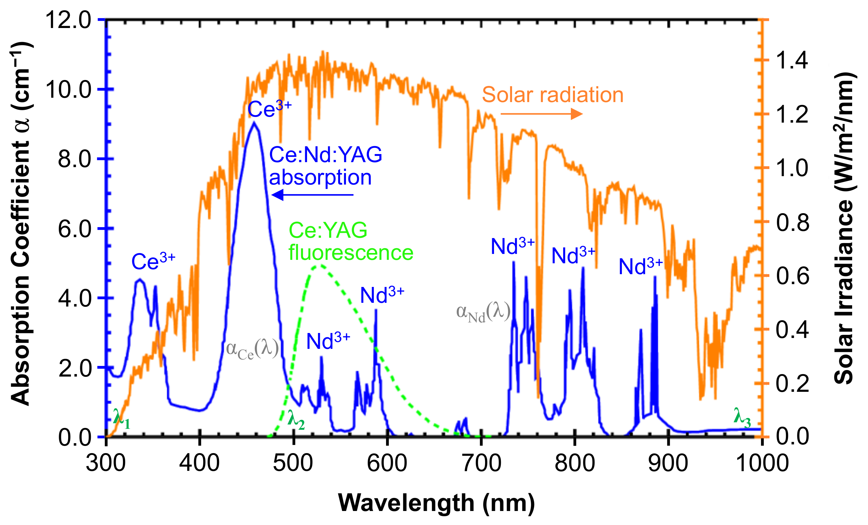
  20. Tai, Y.; Zheng, G.; Wang, H.; Bai, J. Near-infrared quantum cutting of Ce3+–Nd3+ co-doped Y3Al5O12 crystal for crystalline silicon solar cells. J. Photochem. Photobiol. A Chem. 2015, 303–304, 80–85. [Google Scholar] [CrossRef]
  21. Yagi, H.; Yanagitani, T.; Yoshida, H.; Nakatsuka, M.; Ueda, K. The optical properties and laser characteristics of Cr3+ and Nd3+ co-doped Y3Al5O12 ceramics. Opt. Laser Technol. 2007, 39, 1295–1300. [Google Scholar] [CrossRef]
  22. Guo, Y.; Huang, J.; Ke, G.; Ma, Y.; Quan, J.; Yi, G. Growth and optical properties of the Nd,Ce:YAG laser crystal. J. Lumin. 2021, 236, 118134. [Google Scholar] [CrossRef]
  23. Payziyev, S.; Sherniyozov, A.; Bakhramov, S.; Zikrillayev, K.; Khalikov, G.; Makhmudov, K.; Ismailov, M.; Payziyeva, D. Luminescence sensitization properties of Ce: Nd: YAG materials for solar pumped lasers. Opt. Commun. 2021, 499, 127283. [Google Scholar] [CrossRef]
  24. Garcia, D.; Liang, D.; Vistas, C.R.; Costa, H.; Catela, M.; Tibúrcio, B.D.; Almeida, J. Ce:Nd:YAG Solar Laser with 4.5% Solar-to-Laser Conversion Efficiency. Energies 2022, 15, 5292. [Google Scholar] [CrossRef]
  25. Liang, D.; Vistas, C.R.; Garcia, D.; Tibúrcio, B.D.; Catela, M.; Costa, H.; Guillot, E.; Almeida, J. Most efficient simultaneous solar laser emissions from three Ce:Nd:YAG rods within a single pump cavity. Sol. Energy Mater. Sol. Cells 2022, 246, 111921. [Google Scholar] [CrossRef]
  26. ASTM G173-03; Standard Tables for Reference Solar Spectral Irradiances: Direct Normal and Hemispherical on 37° Tilted Surface. ASTM International: West Conshohocken, PA, USA, 2012.
  27. Vistas, C.R.; Liang, D.; Garcia, D.; Tibúrcio, B.D.; Almeida, J. 32 W TEM00-Mode Side-Pumped Solar Laser Design. Appl. Sol. Energy 2020, 56, 449–457. [Google Scholar] [CrossRef]
  28. Wang, L.; Xia, C.; Xu, P.; Di, J.; Sai, Q.; Mou, F. Energy transfer in Ce, Nd, and Yb co-doped YAG phosphors. Chin. Opt. Lett. 2013, 11, 061604. [Google Scholar] [CrossRef]
  29. Ciofini, M.; Favilla, E.; Lapucci, A.; Sani, E. Propagation parameters of the beam extracted from a diode pumped Nd:YAG ceramic slab laser with a hybrid stable–unstable resonator. Opt. Laser Technol. 2007, 39, 1380–1388. [Google Scholar] [CrossRef]
Figure 1. Standard solar emission (orange line) [26], Ce:YAG fluorescence (green line) and Ce:Nd:YAG absorption (blue line) spectra (adapted from [23,25], respectively).
Energies 16 05143 g001
Figure 2. Schematics of the solar energy collection and concentration system at PROMES-CNRS (adapted from [12]).
Energies 16 05143 g002
Figure 3. (a) Front-view and (b) side-view of the solar laser head. A V-shaped reflector, V1, and two planar reflectors, V2, constitute the 2V-shaped cavity.
Energies 16 05143 g003
Figure 4. Absorbed spatial distribution of pump power along both the central transversal (up) and longitudinal (down) cross sections of the 4.1 mm diameter grooved Ce:Nd:YAG rod.
Energies 16 05143 g004
Figure 5. Schematic representation of (a) the solar laser head and (b) the symmetric laser resonant cavity. The distance between the HR mirror and the left end face of the laser rod with length LR is denoted by L1, while the separation length of the PR mirror and the laser rod’s right end face is indicated by L2.
Energies 16 05143 g005
Figure 6. The absorbed pump power and the corresponding numerically computed multimode solar laser power.
Energies 16 05143 g006
Figure 7. Heat load, temperature, and stress intensity distributions computed through LASCAD™ analysis for the 4.1 mm diameter grooved Ce:Nd:YAG rod.
Energies 16 05143 g007
Figure 8. Schematic representation of the (a) symmetric and (b) asymmetric laser resonant cavities. The respective laser beam profiles numerically obtained by LASCADTM are also presented (c,d). The distance between the HR mirror and the left end face of the laser rod with length LR is denoted by L1, while the separation length of the PR mirror and the laser rod’s right end face is indicated by L2.
Energies 16 05143 g008
Figure 9. The absorbed pump power and the corresponding numerically computed TEM00-mode solar laser power, using a symmetric optical resonator.
Energies 16 05143 g009
Figure 10. The absorbed pump power and the corresponding numerically computed TEM00-mode solar laser power, using a asymmetric optical resonator.
Energies 16 05143 g010
Figure 11. Computed (a) 3D and (b) 2D TEM00-mode laser beam profile obtained at the output mirror of the resonant cavity with asymmetric configuration for the grooved Nd:YAG rod with diameter 4.1 mm. ω, spot size 1/e2 width.
Energies 16 05143 g011
Disclaimer/Publisher’s Note: The statements, opinions and data contained in all publications are solely those of the individual author(s) and contributor(s) and not of MDPI and/or the editor(s). MDPI and/or the editor(s) disclaim responsibility for any injury to people or property resulting from any ideas, methods, instructions or products referred to in the content.

