Article

Potential Energy Recovery and Direct Reuse System of Hydraulic Hybrid Excavators Based on the Digital Pump

1
Energy and Power Engineering College, Lanzhou University of Technology, Lanzhou 730050, China
2
School of Mechanical Science and Engineering, Huazhong University of Science and Technology, Wuhan 430074, China
*
Author to whom correspondence should be addressed.
Energies 2023, 16(13), 5229; https://doi.org/10.3390/en16135229
Submission received: 14 June 2023 / Revised: 3 July 2023 / Accepted: 6 July 2023 / Published: 7 July 2023
(This article belongs to the Special Issue Advanced Fluid Power and Mechatronics)

Abstract

:
The potential energy recovery of hydraulic excavators is very significant for improving energy efficiency and reducing pollutant emissions. However, the more common solutions for potential energy recovery require more energy conversion processes before these potential energies can be reused, which adds to the complexity and high cost of the system. To tackle the above challenges, we proposed a novel energy recovery system for hydraulic hybrid excavators based on the digital pump with an energy recovery function. The new system could operate in three different modes: pump, energy recovery, and direct reuse. Based on the descriptions of the working principle of the digital pump and the whole energy recovery system, the mathematical models of the digital pump, the excavator arm cylinder, and the accumulator were established and the AMESim simulation model (combining mechanics, hydraulics, and electrics) was developed. The dynamic characteristics of the energy recovery system were studied under no-load and full-load conditions. The simulation results showed that this scheme could achieve 86% energy recovery when the boom was lowered and reused the recovered energy directly when raised, which could decrease the system input energy by 78.1%. This paper can provide an optimized solution for construction machinery or off-road vehicles and presents a reference for the research on digital hydraulics.

1. Introduction

In the face of the increasingly prominent energy shortage and environmental protection issues in recent decades, the problems of energy utilization in construction machinery are particularly significant [1]. As the working conditions of construction machinery are different from that of cars, it is difficult for the engines to achieve the best power matching, high energy efficiency and low carbon emissions. Earlier researchers found that the effective energy use rate of construction machinery was only 30% [2]. The mixed drive of construction machinery is an inevitable development trend; an ideal energy-saving and emission-reducing drive can be achieved [3,4,5]. Moreover, achieving energy recovery in hydraulic hybrid excavators can greatly improve overall efficiency; hence, the recovery of potential energy is a very promising research direction. To achieve these goals, researchers have investigated three directions of potential energy recovery: mechanical, electrical, and hydraulic [6]. The mechanical energy recovery method has been represented by the use of flywheel energy storage systems. Li et al. combined a flywheel with a flow regeneration circuit, which could improve the energy recovery efficiency by 13% and increase the reuse efficiency by 62% compared with systems that only d flywheel energy storage [7,8]. A representative example of an electrical energy recovery solution is the combination of a supercapacitor with a motor. Yang et al. designed a boom energy recovery system using supercapacitors for energy storage; simulations showed that the energy consumption of the system decreased by 20.72% in a single work cycle [6]. The hydraulic scheme consisted of a hydraulic accumulator and a hydraulic motor or pump. Some researchers also introduced supercapacitors into hydraulic solutions or applied the solution to energy recovery in other components of excavators. Li et al. applied the combination of supercapacitors and accumulators for boom energy recovery, reducing energy consumption by 29% [9]. Lin et al. studied the process of lowering the boom and rotating the turntable of a hybrid excavator and proposed an energy recovery system that combined a hydraulic motor and a generator [10,11]. Liu et al. used a combination of hydraulic motors, electric motors, and supercapacitors for energy recovery during the braking of the excavator rotating platform, achieving a recovery efficiency of over 40% [12]. By adding a third energy utilization cylinder for recovery to the original boom dual-cylinder drive system, it was also possible to achieve the recovery of boom potential energy [13,14,15].
However, the above energy recovery solutions using traditional hydraulic technology increased the complexity of the system structure and control and the costs were further increased. Digital hydraulic technology, with its intelligent control methods, excellent application prospects, and high efficiency characteristics, provides a new feasible solution for traditional hydraulic technology iteration upgrades [16,17]. As a new type of high-efficiency energy conversion equipment, digital displacement pumps (DDP) are very promising for use in off-road equipment, mining machinery, or energy systems [18]. Based on data from a project to retrofit a 99 cc DDP to an excavator, parallel testing of the retrofitted excavator with an unmodified excavator resulted in a 28% increase in productivity and a 10% reduction in fuel consumption at full speed [19]. Joseph J. et al. applied DDP to the crawler excavator for further experimental study. They found that the average efficiency of the pump was increased by 6% and the output was increased by 10–17.5% [20]. John Hutcheson et al. demonstrated the high energy recovery potential of the DDPM by comparing the DDPM with the swashplate pump in the load-sensitive system and the displacement control system, taking the 10 t boom as an example [21].
In conclusion, adopting digital displacement technology can simplify the system structure and efficiently utilize energy; however, these digital machines can only be used in a single mode during the working process (as pumping mode or as motoring mode). Therefore, we proposed a new type of digital pump system that could achieve energy recovery and direct reuse system (ERDRS), in which the digital pump could achieve direct reuse mode. The direct reuse mode means that the digital pump runs simultaneously in pumping and motoring mode, which can fully utilize the suction stroke and pressure stroke of the digital pump.
In this paper, we took the potential energy recovery during the lowering of a 1 t excavator boom as an example. Firstly, we explained how the new proposed digital pump worked and included the schematic diagram of three operation modes of ERDRS applied to a hydraulic hybrid excavator in Section 2. Secondly, we conducted mathematical modeling of the digital pumps, actuators, and accumulators of the ERDRS in Section 3. Then, in Section 4 we developed a simulation modeling of a 1 t hydraulic hybrid excavator boom and validated it with data under no-load conditions. To verify the effectiveness of the ERDRS, in Section 5, we investigated the system characteristics of the three operating modes of ERDRS at no-load and full-load conditions. Finally, we concluded that ERDRS allowed for 86% of boom potential energy to be recovered into the accumulator for storage and direct reuse, reducing the external input energy of the boom hydraulic system by 78.1%. Notably, adjusting the operating parameters of the digital pump could obtain a torque input close to 0 (which is worthy of further research). Improving the efficiency of the digital pump could further improve the above-mentioned results. The proposed scheme also simplified the complexity of the system and provided a significant guideline for creating greater efficiencies of construction machinery.

2. Potential Energy Recovery and Direct Reuse Energy Recovery System

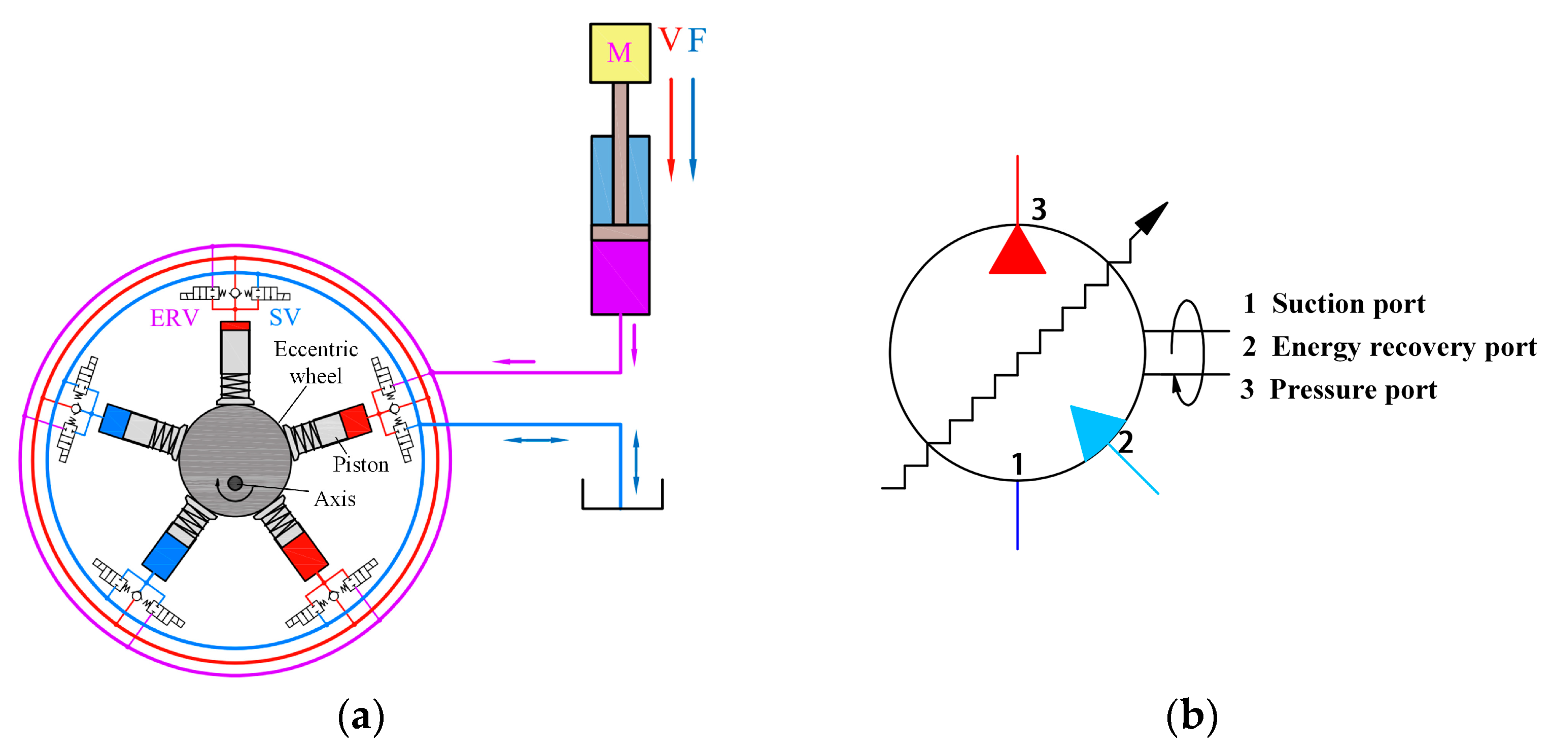
2.1. Structure and Working Principles of the Digital Pump

The structure schematic of the digital pump with five pistons is shown in Figure 1a. It is obvious that the digital pump mainly consisted of piston pairs, an eccentric wheel, and flow distribution valve groups. Each piston pair was equipped with a suction valve (SV), an energy recovery valve (ERV), and a check valve. Accordingly, the digital pump had a suction port, an energy recovery port, and a pressure port, which is illustrated in Figure 1b. The eccentric wheel driven by a motor rotated and the piston was forced by the eccentric wheel to achieve a sinusoidal variation of the sealed volume.
Figure 2 shows the timing diagram of the variable displacement control of the digital pump. At all stages of the piston sinusoidal motion of the digital pump, the opening duration of SV was regulated to enable the fluid to flow freely between the sealed volume chamber and the tank through the suction port. By opening the ERV in the suction stroke, the high pressure fluid would flow from the energy recovery port into the piston chamber. The piston was compelled to move by hydraulic force and helped the eccentric wheel to rotate, which fully utilized the suction stroke of the digital pump and provided the same function as the digital motor. SV and ERV could not be energized simultaneously; the check valve prevented fluid backflow from the pressure port.

2.2. Structure and Working Principles of the ERDRS

Combined with an accumulator, the energy recovery digital pump described above was applied to a hydraulic hybrid excavator to constitute an ERDRS system, as shown in Figure 3. The structure and working principles of the three working states that the system could achieve are analyzed as follows:

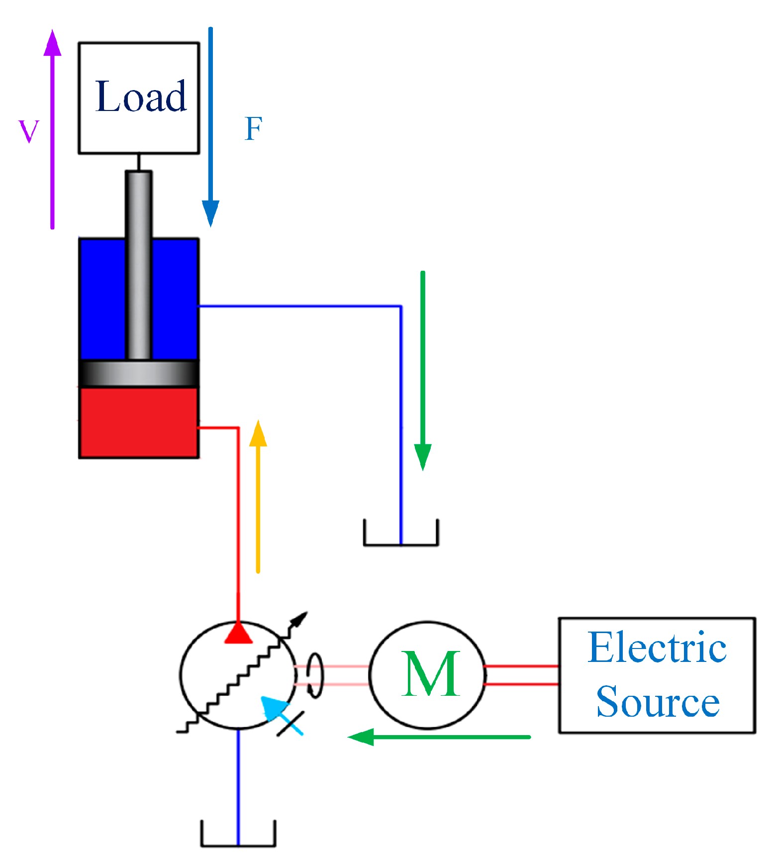
2.2.1. Pumping Mode Operation (PM)

Figure 4 shows the system diagram when the digital pump was used as the pumping mode to drive the boom cylinder. An electric motor, converting the input electrical energy into mechanical energy, was used as the prime mover of the system to drive the rotation of the digital pump. After the rotation of the digital pump, the fluid in the tank was delivered to the rod-less chamber of the boom cylinder to realize the transformation from mechanical energy to fluid pressure energy. The oil in the rod chamber of the cylinder returned to the tank through the low pressure line. The ERV of the digital pump was kept closed during the whole process and the energy recovery function was banned. It was clear that ERDRS was a pump control system in this mode; the movement speed regulation of the actuator could be achieved by controlling the flow rate into the rod-less chamber, i.e., by controlling the output displacement coefficient (ODC) of the digital pump. Another thing to note was that this system could achieve higher efficiency due to the replacement of the general hydraulic pump with a digital pump.

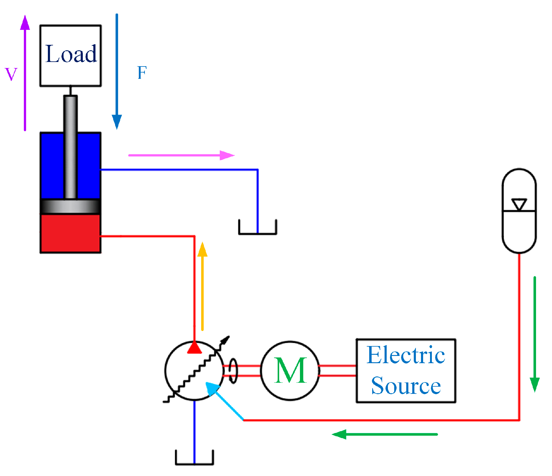
2.2.2. Energy Recovery Mode Operation (ERM)

Figure 5 demonstrates a schematic diagram of the ERDRS working in ERM. When the boom was lowered, the energy recovery function of the digital pump was enabled. The fluid recovered was pumped to the accumulator for storage through the pressure port. The transformation of the boom potential energy into the pressure energy of the accumulator was realized with the above process, which meant that potential energy recovery was achieved. Although the digital pump had its energy consumption, the percentage of energy consumed was very small compared with the total energy recovered. In addition, this consumption could be reduced by optimizing the structure and manufacturing accuracy of the digital pump or by working at the best possible operating point. During the process of boom lowering, the speed of the boom cylinder could be controlled by changing the energy recovery coefficient (ERC) of the digital pump. The size of the ERC was proportional to the switching times of the energy recovery valve. To achieve maximum energy recovery and to minimize the external input electrical energy to the system, it was essential to find a balance between the ERC and the ODC of the digital pump during the process of charging the accumulator.

2.2.3. Direct Reuse Mode Operation (DRM)

The schematic picture of the ERDRS directly reusing the recovered energy in the accumulator is displayed in Figure 6. When the boom actuator was raised, the system switched to DRM and the fluid stored in the accumulator entered the piston volume of the digital pump. In this case, the electric motor and accumulator jointly drove the digital pump to deliver fluid to the rod-less chamber of the boom cylinder; the conversion of hydraulic energy in the accumulator and electrical energy into the potential energy of the actuator was successfully realized. The energy stored in the accumulator was the main contributor to driving the rotation of the digital pump; the electric motors only played an auxiliary role in this process. If an appropriate ERC and ODC were selected, the released power of the accumulator was balanced with the power that drove the actuator movement. The electric motor only provided the energy consumed by the digital pump itself and kept the speed of the digital pump constant. If the energy recovered in the accumulator was not sufficient to meet the reuse requirements, the corresponding energy gap was filled by the electrical energy consumed by the motor.

3. Mathematical Modeling of ERDRS

From the above analysis of the working modes, it could be concluded that the energy recovery system applied to the boom was similar to that of the arm and bucket. Therefore, this paper took boom potential energy recovery as an example, which did not affect the validation of the effectiveness of the new system.

3.1. Boom Cylinder Energy Characteristics

When the boom was lowered, the potential energy of the boom was converted into the fluid pressure energy of the rod-less cavity:
E = t 1 t 2 P s Q s d t
where P s is the pressure of the rod-less cavity, Q s is the flow rate of the rod-less cavity, and t 1   t 2 are the start descent time and the complete descent time. The flow of fluid from the rod-less cavity when the boom was lowered:
Q S = v π D 2 4

3.2. Hydraulic Cylinder Characteristics

The kinetic equations of the hydraulic cylinder can be expressed as follows:
F 1 A 1 F 2 A 2 = m v ˙ + B v + F t + F L
In the formula, F 1 and F 2 are the rodless cavity pressure and rod cavity pressure, respectively; A 1 and A 2 are the areas of the rodless cavity and the area of the rod cavity, respectively; m is the equivalent mass of the piston rod and the load; B is the damping coefficient; F t is the friction; F L is the force of the rod. The continuity equation of the hydraulic cylinder can be expressed as:
Q 1 A 1 = Q 2 A 2
where Q 1   and Q 2   are the flow rates of the rod-less cavity and the rod cavity; A 1   and   A 2   are the acting areas of the rod-less cavity and the rod cavity.

3.3. Working Characteristics of the Digital Pump

The digital pump could be reducible to the combination of the plunger pump and the digital valve that is presented in Figure 7. The influence of the dead zone volume of the plunger cavity was negligible.
x = L 2 1 cos θ
where L is the effective length of the plunger. The relationship between angular displacement and the angular velocity of the axis:
θ = ω t
Equation (6) is the angular velocity of the pump shaft rotation. By substituting Equation (6) into Equation (5), we can obtain:
x = L 2 1 cos ω t
By differentiating Equation (9), the piston velocity equation is achieved as follows:
x ˙ = L 2 ω sin ω t
According to the flow calculation formula:
Q = V · A = π D 2 L 8 ω sin ω t α
The torque equation can also be obtained; α is the coefficient of displacement
T p = V · p ·   α 20 π

3.4. Accumulator Characteristic Change

In this paper, the volume change process of the gasbag accumulator used was regarded as an isothermal process. Therefore, according to the ideal gas state equation, the following equation was obtained:
P 0 V 0 n = P 1 V 1 n = P 2 V 2 n = c o n s t
where P 0   is the initial working pressure of the accumulator, V 0   is the initial volume of the accumulator, P 1   is the normal working pressure of the accumulator, V 1   is the gas volume when the accumulator pressure is P 1 , P 2   is the maximum working pressure of the accumulator, V 2 is the gas volume when the accumulator pressure is P 2 , and n is the gas variation index. Let the isothermal process be 1 and the adiabatic process be 1.4. According to the empirical formula [22]:
P 1 = 0.6 0.85 P 0
P 2 = 1.1 1.5 P 0
The initial volume of the accumulator can be calculated:
V 0 = V P 0 P 2 / P 1 1 n 1
The energy that the accumulator can recover is:
E R E = V 0 V 1 P d V = V 0 V 1 P 0 V 0 V 1 n d V =         P 0 V 0 n 1 P 1 P 0 n 1 / n 1
The inlet flow of the accumulator can be expressed as:
Q a c c = d V a c c d t

4. Simulation Modeling and Investigation

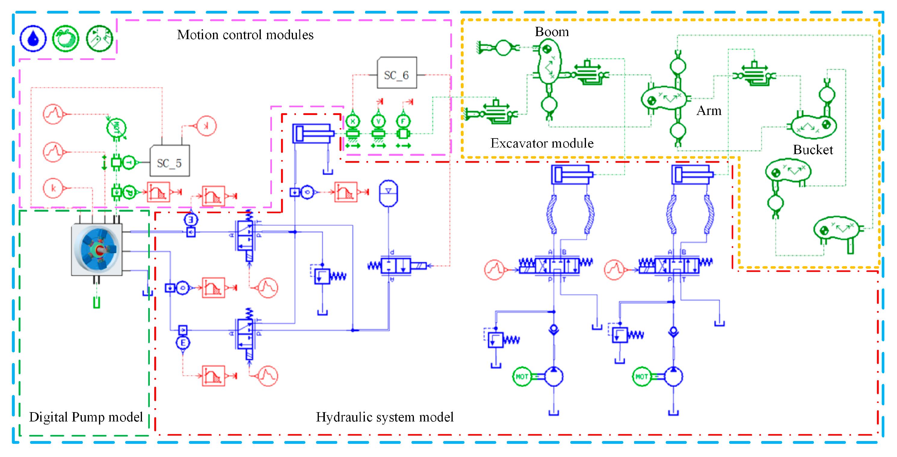
4.1. Simulation Model of ERDRS

According to the structure and working principle of ERDRS, the three different disciplines such as mechanical, hydraulic, and electrical were involved in its working process. On account of the most powerful capabilities of multidisciplinary modeling, the AMESim R15 software was adopted as a modeling platform for convenience. The mechanical library, hydraulic library, signal library, and planer mechanical library in AMESim were used to build the models of the ERDRS, as shown in Figure 8.
From the established AMESim model, the ERDRS model was mainly composed of the hydraulic system module, motion control module, digital pump module, and excavator module. In particular, the motion control module also contained signal control components and mechanical components. The SC_5 was a signal control module that was set up to adjust the ODC of the digital pump according to the real-time input torque of the motor. The SC_6 was used to detect the displacement of the boom cylinder so that the accumulator outlet valve was switched on or off. The modeling of the digital pump module was based on the principal analysis of the second part and the parameter extracted from the digital pump prototype. The relevant parameters are listed in Table 1.

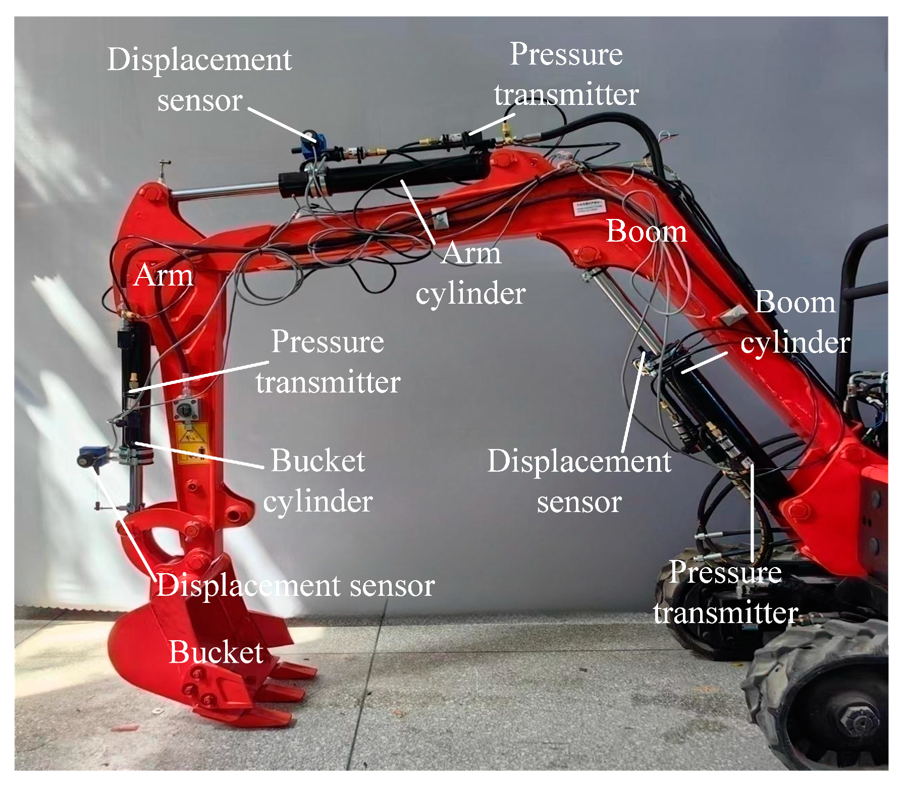
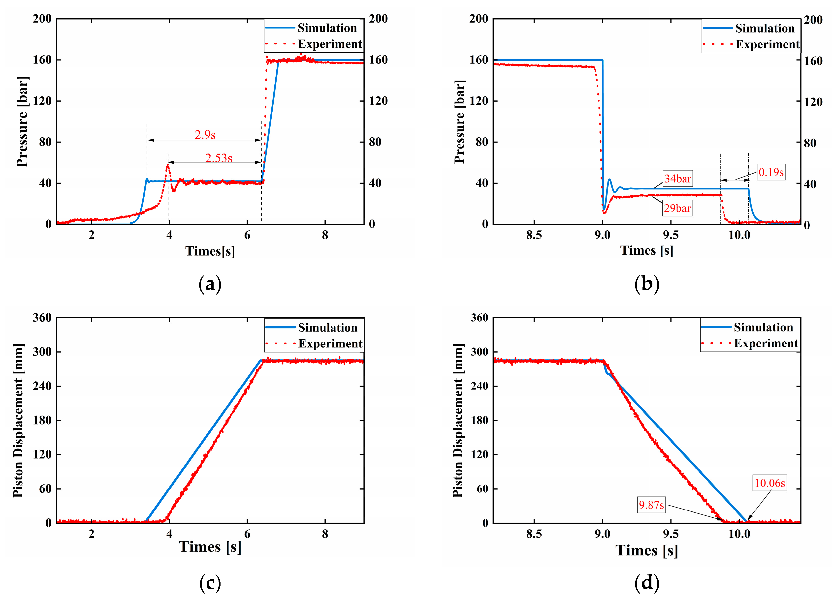
4.2. Model Accuracy Validation

A photograph of the excavator prototype used for the experimental validation is shown in Figure 9. The data acquisition device for the boom consisted mainly of two pressure transmitters, with 0.5% measurement accuracy, and a pull-wire displacement sensor, with 0.1% measurement accuracy. It was also equipped with data acquisition cards, such as PCI-6259 by National Instruments (NI), which could implement 32-channel AI (16-bit, 1.25 MS/s), 4-channel AO (2.8 MS/s) data acquisition, and LabVIEW Signal Express tasks. According to Table 1, the maximum flow rate of the digital pump used in this case was 2.98 L/min. To match the actual flow rate of this digital pump, the piston and rod diameters of the boom cylinder were chosen, as shown in Table 2. Figure 10 presents the comparative curves of working characteristics when the boom cylinder worked with no load. In the rising phase of the boom, the boom started to move up when the pressure in the rod-less cavity reached 40 bar. The boom cylinder entered overflow status, where the pressure was limited to 160 bar when the piston displacement exceeded the maximum stroke of 285 mm. The ascent process lasted 2.9 s and 2.53 s in the simulation and the experiment, respectively. When the boom displacement declined at 9 s, the pressure in the rod-less cavity dropped suddenly and then rose again to a stable pressure in a short time, such as 34 bar in the simulation and 29 bar in the experiment, until the boom dropped to the lowest position. The difference between the time used for descent in the simulation and in the experiment was 0.19 s. The trend and shape of the simulation curves were very close to those drawn from the experimental data and the deviations were acceptable, which verified the usability of the model.

5. Simulation Analysis of the ERDRS under Different Operating Conditions

To further study the performance of the system under different operating conditions and to verify the feasibility of the scheme, the PM, ERM, and reuse modes under no-load and full-load conditions, respectively, were simulated and studied; among them, the PM operation under no-load conditions was analyzed in Section 4.2.

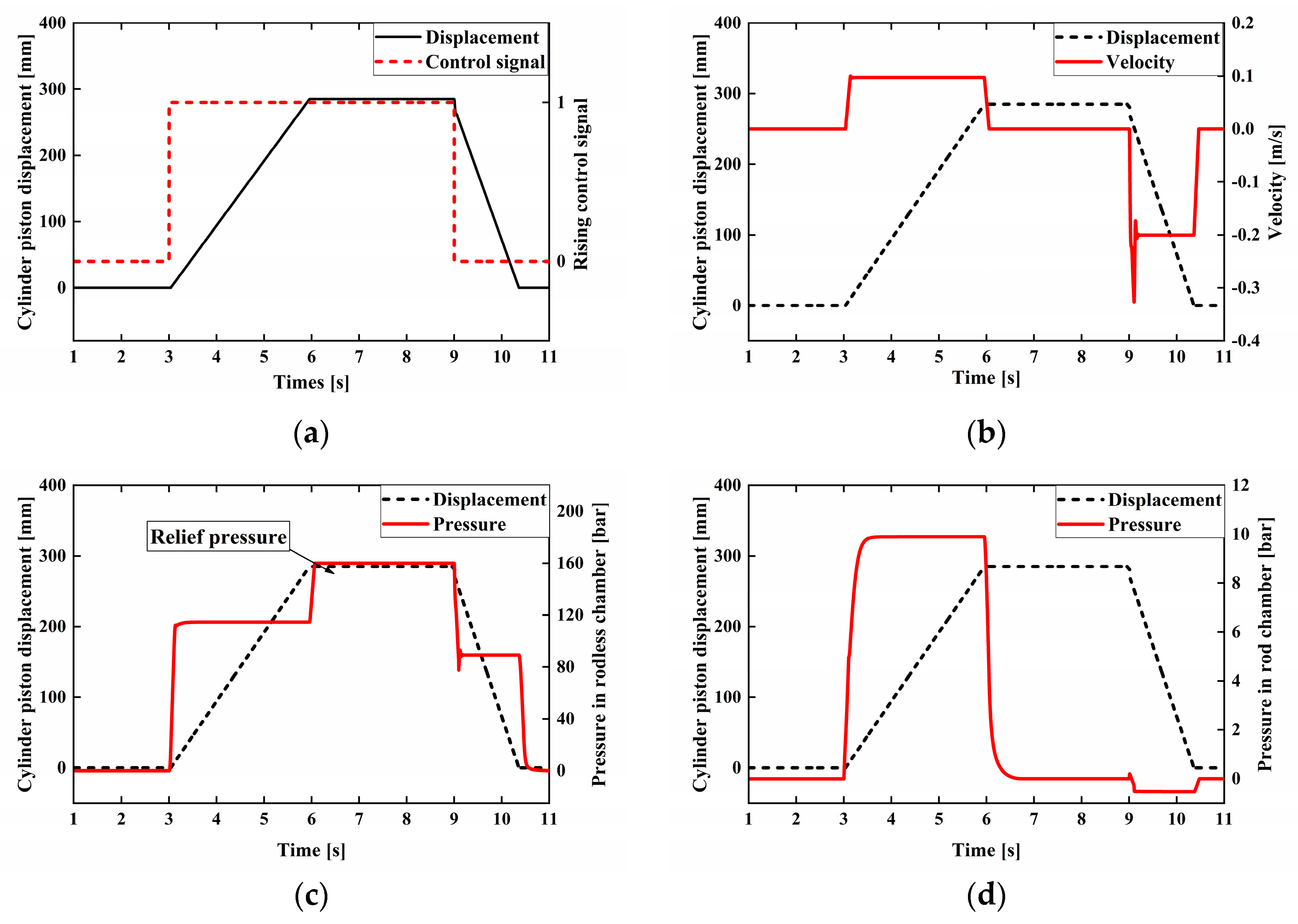
5.1. No-Load Operation

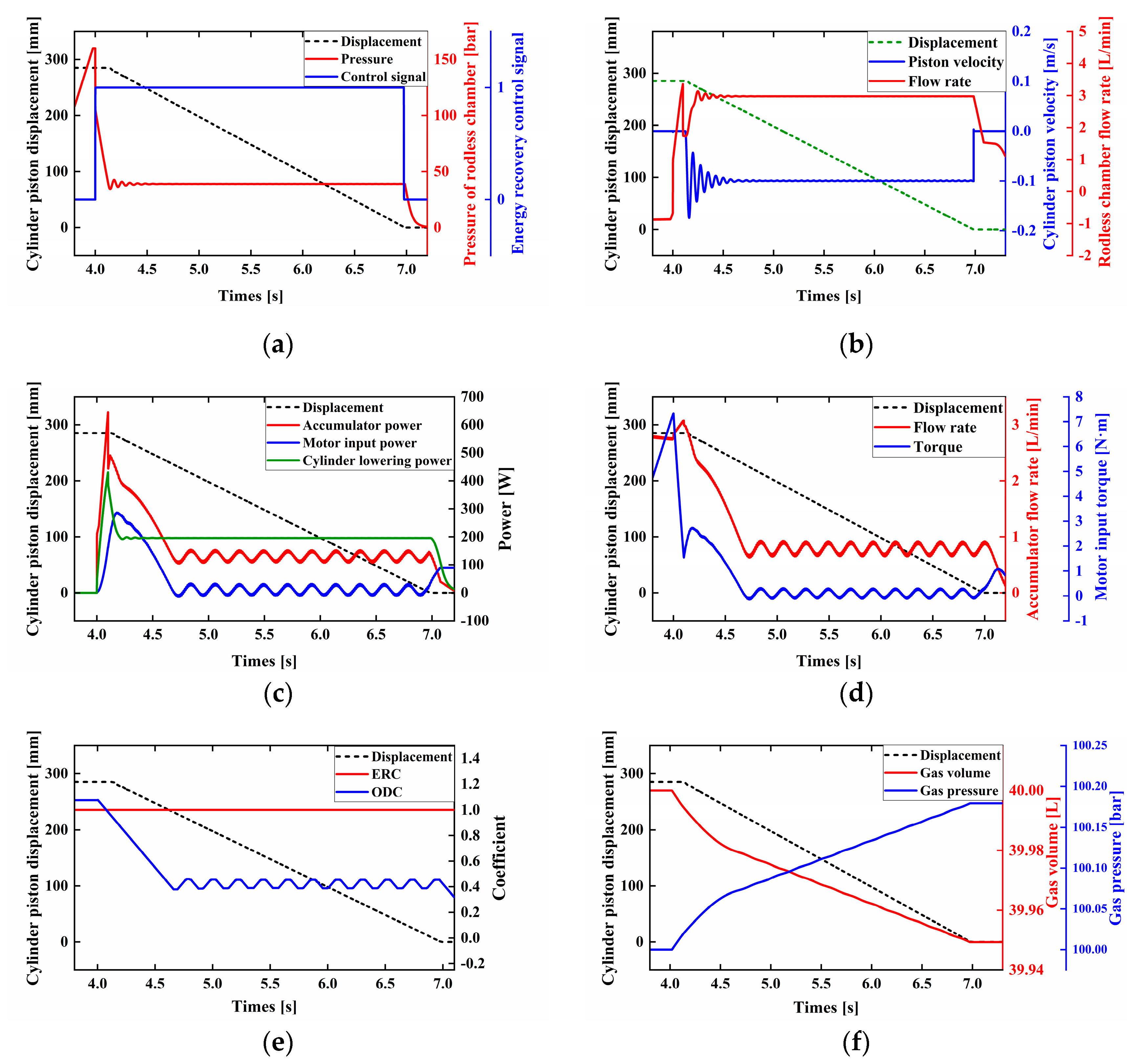
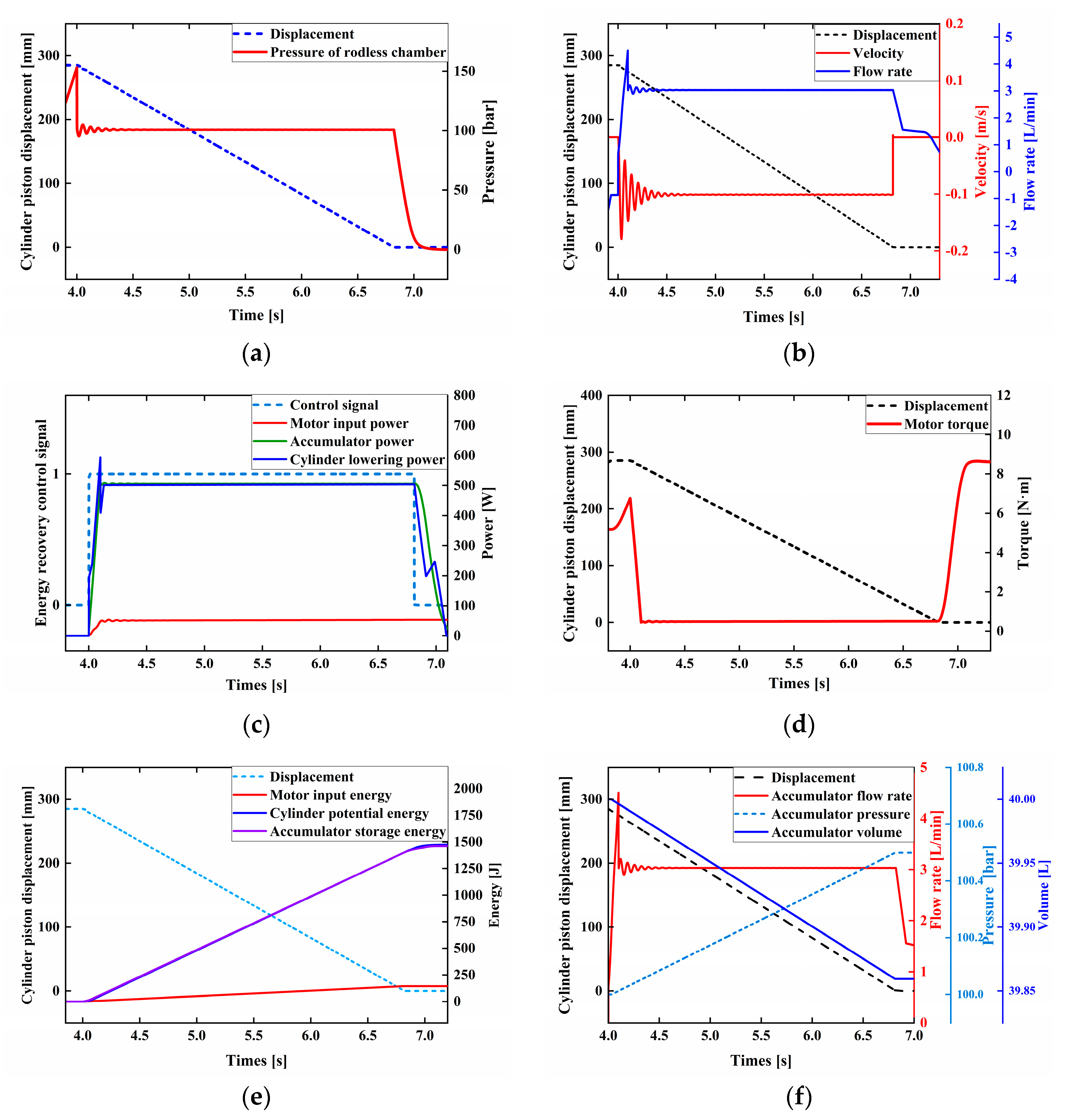
5.1.1. ERM Operating Characteristics

As shown in Figure 11a, the boom cylinder lowered from 4 s to 7 s under the no-load condition. When the boom started to lower, the ERM of the ERDRS was switched on. The fluid in the rod-less chamber of the boom cylinder entered the digital pump through the energy recovery port and drove the piston movement, so the pressure in the rod-less chamber was reduced to 38 bar rather than a lower pressure. To ensure the speed of the boom was within the safety range, the speed of lowering was maintained at 0.1 m/s by adjusting the ERC, which can be seen in Figure 11e. Due to the small displacement of the digital pump we used, the corresponding recovery flow rate was 2.98 L/min when the ERC was adjusted to the maximum value of 1. In addition, this also made a flow rate of 2.9 L/min for the descent process of the cylinder; the power of the cylinder descent was also stabilized at 200 W. To verify that this scheme could achieve the reduction of external input energy, the ODC of the digital pump was automatically reduced between 4 s and 4.75 s, as seen in picture (e). Furthermore, the above was also evidenced by the decrease in the power in picture (c) and the reduction of the accumulator inlet flow rate in picture (d). From Figure 11c,d,f, it can be seen that about 150 W of the 200 W power during the drop of the boom was recycled and used to charge the accumulator by the digital pump. This validated that the potential energy of the boom was converted into hydraulic energy of the accumulator by the digital pump; the rest was used for the consumption of the digital pump itself, as seen in picture (c). During this process, the input power of the motor fluctuated around 0 and the input torque of the motor also decreased to around 0; the motor only performed auxiliary work such as stabilizing the rotational speed.

5.1.2. DRM Operation Characteristics

When the boom rose under no-load conditions, the DRM of ERDRS and the coefficient automatic adjustment module were activated. In this simulation, the boom was lifted in 2–5.8 s. When the pressure in the rod-less chamber of the boom cylinder rose to 40 bar, it overcame the resistance and gravity to rise. During the early stages of motion, there was a slight fluctuation in speed, which was quickly maintained around 0.1 m/s. As can be seen in Figure 12e, the ODC of the pump varied around 0.9 after starting the automatic coefficient change module, resulting in a change in the flow rate into the rod-less chamber of the boom cylinder. As seen in Figure 12c,d, during the initial 2–2.5 s of the upward movement, the pressure in the rod-less chamber of the boom did not rise. The reaction torque on the digital pump shaft was very small due to the digital pump pumping the fluid from the pressure port to the rod-less chamber of the cylinder. Therefore, 250 W of the power released from the accumulator was output through the motor and the accumulator had an initial peak power of 450 W. During the period 2.5–5.5 s, the boom overcame the resistance and gravity to rise. An amount of 197 W from the 240 W power released by the accumulator was used to drive the boom movement. The remaining power was used to meet the digital pump’s consumption and other energy losses. From Figure 12c,d, after the automatic change of coefficient, the input torque of the motor was approximately 0 and the input power of the motor was only 23 W. Combining the variation in the properties of the accumulator in picture (f), the hydraulic energy stored in the accumulator was converted into potential energy for the lowering of the boom by using the digital pump; the application of this scheme under no-load conditions was effective.

5.2. Full-Load Operation

5.2.1. PM Operation Characteristics

Figure 13 shows the working characteristics of ERDRS adopting PM to drive the boom rising under full-load conditions. The raising control signal was activated within 3–9 s to drive the boom rising. Then, the rising signal was stopped to make the boom lower. From Figure 13b, the rising speed of the boom was 0.1 m/s and the lowering speed was 0.2 m/s. The rising speed of the boom was controlled by adjusting the ODC of the digital pump. The coefficient control scheme used in this paper was not unique and was not the main focus of this research; thus, not much attention was paid to it. It can be seen from Figure 13c,d that, under full-load conditions when the pressure of the rod-less chamber of the boom cylinder increased to 110 bar, the boom was able to overcome the resistance and gravity to rise. When the cylinder reached the maximum stroke, the system entered a relief pressure of 160 bar. During the raising and lowering process, the pressure in the rod cavity also increased due to the backflow pressure at the outlet; the curve trend was similar to the experimental data plotted.

5.2.2. ERM Operating Characteristics

Figure 14 shows the system characteristics when the ERDRS was switched to the ERM during the boom lowering process under full-load conditions. Figure 14a,b shows that the boom started to drop at 4 s and the pressure in the rod-less cavity decreased from a relief pressure of 160 bar to a pressure of 100 bar. The pressure in the rod-less cavity was influenced by the force required for the fluid to push the plunger and assist in the rotation of the eccentric wheel. During the lowering process, the speed of the boom was kept at 0.1 m/s in order to meet the safety requirements; the corresponding flow rate of the digital pump was 2.9 L/min. It was realized that the gravitational potential energy of the boom was transformed into hydraulic energy of the accumulator, as seen in picture (f). For testing the ideal potentials for energy recovery of this solution under full-load conditions (the system did not require external energy input for energy recovery), the automatic control of the digital pump ODC in the simulation model was activated. As shown in Figure 14c,d, after adjusting the ODC of the digital pump, the input torque of the motor was reduced approximately to 0. The recovery power of the accumulator and the power of the boom lowering were both 500 W. This meant that the motor was only supplemented by a small amount of the 60 W of power consumed to maintain the digital pump itself for the stable operation of the system. Therefore, this scheme achieved the energy recovered from the energy curve in Figure 14e and the working state of the accumulator in picture (f).

5.2.3. DRM Operation

Figure 15 shows the working characteristics of the ERDRS switching to the DRM when the boom rose under full-load conditions. From Figure 15a, it can be seen that during the initial stage of ascent, there were transient fluctuations in speed and flow rate, but it quickly remained stable at 2.9 L/min. The fluid pressure released by the accumulator into the sealed volume through the energy recovery port of the digital pump was high and the pressure of the fluid did not decrease enough when the fluid was pumped to the pressure port after pushing the piston movement. The ODC of the digital pump directly affected the flow rate charging into the rod-less chamber of the boom cylinder, controlling the movement speed of the boom. In this simulation, the running speed was still adjusted to 0.1 m/s. As shown in Figure 15b, from the comparison of motor torque between the new system (DRM) and the original system (PM system), it was verified that the new system required less than 88.37% torque.
From Figure 15c,d, it can be seen that the accumulator release power and the driving actuator power were the same at 515 W. In other words, the main contributor to the driving actuator was the recovered fluid in the accumulator. The motor only needed to supplement the power consumed by the digital pump itself and stabilized the rotational speed to ensure the stable operation of the system. But the energy recovered was not enough to be repurposed at the next time in all cases. If the recovered hydraulic energy was less than that of elevating the load (and the digital pump itself also consumed a portion of recovered energy), this resulted in the electric motor consuming more electricity to fill the energy gap, as validated in Figure 15d,e. Picture (f) shows a comparison of the input energy of the motor during the rise of the boom cylinder between the original system and the new system under full-load conditions; it was concluded that the energy recovery rate of the new system was approximately 86%, which could save about 78% of the input energy compared with the original system.

6. Conclusions

In this paper, a new potential energy recovery and direct reuse system (ERDRS) for hydraulic hybrid excavators based on the digital pump was proposed. The system was based on a new type of digital pump with an energy recovery function. This digital pump could operate in a “Direct Reuse” mode (fully utilizing the suction stroke and the pressure stroke of the digital pump). In order to evaluate the application potential of ERDRS, we took the potential energy recovery and drive upward of the boom of a 1 t hybrid hydraulic excavator as an example. Based on the description of the principles of three operating modes (PM, ERM, and DRM), we developed the mathematical modeling of the digital pump, boom cylinders, and accumulator. The working characteristics of the ERDRS in three operating modes under no-load and full-load conditions were investigated using AMESim R15 software.
Simulation results showed that ERDRS could recover potential energy and store it in the accumulator. When it switched to DRM, the energy recovered by the accumulator was allowed to be released to drive the actuator. By increasing the ERC of the digital pump, the input torque of the digital pump was reduced close to 0, which achieved the reduction of the external input energy (electrical energy) required by the system. Thus, the effectiveness of the solution was validated. In addition, increasing the ODC of the digital pump increased the input torque of the motor and increased the external energy consumption of the system. Compared with systems using only the PM, the ERDRS with ERM and DRM achieved 86% energy recovery and 78% reduction in external energy input to the system in the reciprocating motion test of the boom cylinder.
This scheme has provided new ideas and schemes for simplifying and arranging the hydraulic system of a hybrid excavator. Although the recovery of boom potential energy was taken as an example in this paper, it can still provide ideas for the energy recovery of other parts and other off-road equipment, as well as for the efficient utilization of energy. In the future, we will apply the results of this paper to the experimental bench of the digital pump for experimental verification. The coefficient balance control strategy of the system will be studied and intelligent control will be implemented in combination with different operating modes.

Author Contributions

Conceptualization, Y.L. and L.W.; methodology, L.W.; software, D.Y. and H.G.; validation, D.Y., H.G. and Z.L.; formal analysis, Y.L. and L.W.; investigation, H.G. and X.Z.; resources, L.W.; data curation, Z.L. and D.Y.; writing—original draft preparation, D.Y. and H.G.; writing—review and editing, Z.L. and X.Z.; visualization, H.G.; supervision, Z.L.; project administration, Z.L.; funding acquisition, L.W. and D.Y. All authors have read and agreed to the published version of the manuscript.

Funding

This research was funded by the National Key R&D Program of China (Grant No. 2020YFB2009803).

Data Availability Statement

Not applicable.

Conflicts of Interest

The authors declared no potential conflict of interest with respect to the research, authorship, and publication of this article.

Nomenclature

ERDRSEnergy recovery and direct reuse system
SVSuction valve
ERVEnergy recovery valve
PMPump mode
ERMEnergy recovery mode
DRMDirect reuse mode
ERCEnergy recovery coefficient
ODCOutput displacement coefficient

References

  1. Yang, H. Progress and Trend of Construction Machinery Intelligence. Constr. Mach. Technol. Manag. 2017, 30, 19–21. [Google Scholar] [CrossRef]
  2. Vukovic, M. An Overview of Energy Saving Architectures for Mobile Applications. In Proceedings of the 9th International Fluid Power Conference (9th IFK), Aachen, Germany, 24–26 March 2014. [Google Scholar]
  3. Lin, Y.; Lin, T.; Chen, Q.; Li, Z.; Fu, S.; Ren, H.; Guo, T. Research Progress on Key Technologies of Electric Construction Machinery. Chin. Hydraul. Pneum. 2021, 45, 1. [Google Scholar]
  4. Tong, Z.M.; Miao, J.Z.; Li, Y.S.; Tong, S.G.; Zhang, Q.; Tan, G.R. Development of electric construction machinery in China: A review of key technologies and future directions. J. Zhejiang Univ. Sci. A 2021, 22, 245–264. [Google Scholar] [CrossRef]
  5. Liu, J.-X.; Jiao, Z.-Y.; Wang, Y.; Li, Q.-Y. Research Progress of Energy Regeneration and Utilization System for Hydraulic Excavator. Chin. Hydraul. Pneum. 2018, 5, 81–87. [Google Scholar]
  6. Yang, L.; Luo, Y.; Luo, Y.; Zhou, S. Analysis of Energy Recovery System of Electric Excavator Boom. Mach. Tool Hydraul. 2023, 51, 141–146. [Google Scholar]
  7. Li, J.; Zhao, J. Energy recovery for hybrid hydraulic excavators: Flywheel-based solutions. Autom. Constr. 2021, 125, 103648. [Google Scholar] [CrossRef]
  8. Li, J.; Zhao, J.; Zhang, X. A Novel Energy Recovery System Integrating Flywheel and Flow Regeneration for a Hydraulic Excavator Boom System. Energies 2020, 13, 315. [Google Scholar] [CrossRef] [Green Version]
  9. Li, J.; Cheng, H.; Quan, L.; Hao, Y.-X.; Guan, C. Research on the Electro-hydraulic Energy Recovery and Reuse System in Compound Operation of Pure Electro-hydraulic Excavator. Chin. Hydraul. Pneum. 2020, 12, 44–50. [Google Scholar]
  10. Lin, T.-L.; Ye, Y.-Y.; Fu, S.-J.; Liu, Q. Energy-saving System of Swing for Hydraulic Excavators Based on Electric Energy Recovery Technology. China J. Highw. Transp. 2014, 27, 120–126. [Google Scholar] [CrossRef]
  11. Lin, T.-L.; Ye, Y.-Y.; Wang, Q.-F. Electric Energy Recovery System of Hydraulic Excavator Boom. China J. Highw. Transp. 2013, 26, 184–190. [Google Scholar] [CrossRef]
  12. Liu, C.S.; He, Q.H.; Gong, J. Modeling and experimental research on rotary braking energy recovery system of hybrid excavator. J. Cent. South Univ. 2016, 47, 1533–1542. [Google Scholar]
  13. Tan, L.; He, X.; Xiao, G.; Jiang, M.; Yuan, Y. Design and energy analysis of novel hydraulic regenerative potential energy systems. Energy 2022, 249, 123780. [Google Scholar] [CrossRef]
  14. Geng, J.-X.; Xia, L.-P.; Ge, L.; Quan, L.; Zhang, X.-G. Operation and Energy Efficiency Characteristics of Large-scale Mining Hydraulic Excavator Boom. Chin. Hydraul. Pneum. 2022, 46, 108–115. [Google Scholar]
  15. Hu, P.; Zhu, J.X.; Liu, C.S.; Zhang, D.Q. Characteristics of boom potential energy alternate recovery and utilization system of hydraulic excavator. J. Jilin Univ. 2022, 52, 2256–2264. [Google Scholar] [CrossRef]
  16. Linjama, M. Digital Fluid Power—State of The Art. In Proceedings of the Twelfth Scandinavian International Conference on Fluid Power, Tampere, Finland, 18–20 May 2011. [Google Scholar]
  17. Zhang, Q.W.; Kong, X.D.; Yu, B.; Ba, K.X.; Jin, Z.G.; Kang, Y. Review and Development Trend of Digital Hydraulic Technology. Appl. Sci. 2020, 10, 579. [Google Scholar] [CrossRef] [Green Version]
  18. Danfoss. Data Sheet-Digital Displacement® Pump DDP096 and DPC12; Tomorrow, E., Ed.; Danfoss: Loves Park, IL, USA, 2022; p. 1. [Google Scholar]
  19. Green, M.; Macpherson, J.; Caldwell, N.; Rampen, W.H.S. DEXTER: The Application of a Digital Displacement® Pump to a 16 Tonne Excavator. In Proceedings of the BATH/ASME 2018 Symposium on Fluid Power and Motion Control, Bath, UK, 12–14 September 2018. [Google Scholar]
  20. Budden, J.J.; Williamson, C. Danfoss Digital Displacement® Excavator: Test Results and Analysis. In Proceedings of the ASME/BATH 2019 Symposium on Fluid Power and Motion Control, Longboat Key, FL, USA, 7–9 October 2019. [Google Scholar]
  21. Hutcheson, J.; Abrahams, D.; Macpherson, J.; Caldwell, N.; Rampen, W. Demonstration of Efficient Energy Recovery Systems Using Digital Displacement® Hydraulics. In Proceedings of the BATH/ASME 2020 Symposium on Fluid Power and Motion Control, Virtual, Online, 9–11 September 2020. [Google Scholar]
  22. Wang, F.; Huang, W.-N.; Quan, L. Valve ports independently control the characteristics of hydraulic excavator rotary brake energy recovery system. J. Chongqing Univ. Technol. (Nat. Sci.) 2022, 36, 126–132. [Google Scholar]
Figure 1. Structure and working principle: (a,b) Connection diagram and graphical symbol of the digital pump.
Energies 16 05229 g001
Figure 2. The timing control diagram of the digital pump.
Energies 16 05229 g002
Figure 3. Schematic diagram of ERDRS connection structure.
Energies 16 05229 g003
Figure 4. Pump mode operation.
Energies 16 05229 g004
Figure 5. Energy recovery mode.
Energies 16 05229 g005
Figure 6. Direct reuse mode.
Energies 16 05229 g006
Figure 7. Simplified diagram of the digital pump.
Energies 16 05229 g007
Figure 8. Simulation model of the ERDRS.
Energies 16 05229 g008
Figure 9. 1 t hydraulic excavator for experiments.
Energies 16 05229 g009
Figure 10. No-load operation of PM: (a) pressure in the rod-less cavity when lowering; (b) pressure in the rod-less cavity when rising; (c) piston displacement curve during rising; (d) piston displacement curve during falling.
Energies 16 05229 g010
Figure 11. Characteristics of ERM under no-load conditions: (a) pressure-displacement curve; (b) speed flow curve; (c) power change; (d) pump output flow and input torque; (e) automatic change of coefficient; (f) characteristics of the accumulator.
Energies 16 05229 g011
Figure 12. Characteristics of DRM under no-load conditions: (a) rod-less cavity pressure displacement curve; (b) velocity and flow curves; (c) input torque curve; (d) power curve; (e) automatic change of coefficient; (f) characteristics of the accumulator.
Energies 16 05229 g012
Figure 13. Full-load operation of PM: (a) piston displacement curve; (b) velocity of the cylinder piston; (c) pressure in the rod-less chamber; (d) pressure in the rod chamber.
Energies 16 05229 g013
Figure 14. Characteristics of ERM under full-load conditions: (a) Rod-less cavity pressure displacement curve; (b) velocity and flow curves; (c) input torque curve; (d) power curve; (e) automatic change of coefficient; (f) characteristics of the accumulator.
Energies 16 05229 g014
Figure 15. Characteristics of DRM under full-load conditions: (a) velocity and flow rate; (b) comparison of the input torque; (c) power curve; (d) energy curve; (e) input energy distribution of new system; (f) comparison of input energy.
Energies 16 05229 g015
Table 1. Main performance parameters of the digital pump.
ParameterValueUnit
Pump angular speed1000rpm
The radius of the eccentric31 m m
Piston diameter10 m m
Flow coefficient0.7
Dead volume of piston0.08 m m 3
Chamber length 25 m m
Valve dynamic response3ms
Clearance on diameter1.8 × 10−5mm
Coefficient of viscous friction0.5 N / m / s
Table 2. Main performance parameters of the boom hydraulic cylinder.
ParameterValueUnit
Piston diameter25 m m
Rod diameter14 m m
Length of stroke285 m m
Dead volume 100 c m 3
Viscous friction coefficient500 N / m / s
Disclaimer/Publisher’s Note: The statements, opinions and data contained in all publications are solely those of the individual author(s) and contributor(s) and not of MDPI and/or the editor(s). MDPI and/or the editor(s) disclaim responsibility for any injury to people or property resulting from any ideas, methods, instructions or products referred to in the content.

