1. Introduction
A high quality of high-voltage (HV) insulators aids in the improvement of overhead transmission lines’ (OHTL) performance. These insulators isolate high-voltage electric lines away from the towers while also supporting the conductors by keeping them connected to the towers. Throughout its service life, high-voltage outdoor insulators are subjected to a variety of challenges. One of these hardships is a corona discharge, which occurs as a result of high E-field stress at both ends of the insulator, in all types of insulators. When the electric field (E-field) surpasses the ionization threshold of the air, it triggers the phenomenon known as a corona discharge. A corona discharge manifests itself as energy dissipation, radio interference, and a degradation of polymeric materials in the case of composite insulators. Prolonged occurrences of corona discharge can cause erosion and subsequent damage to the insulating material, ultimately resulting in failure. The geometry and capacitance of the insulator have the biggest impact on the electric field distribution over the insulator surface in dry situations [
1,
2]. Since 2006, maintenance crews of HVTLs have noticed an increase in the number of polymer insulator failures. Investigations have revealed that the failures were caused by large electric fields near or even on the end fittings of these high-voltage insulators. These findings prompted HVTL maintenance engineers to place grading rings on transmission lines’ polymer insulators with system voltages less than 161 kV [
3]. The E-field strength near the insulators increases as the transmitted power levels increase, resulting in the discharge of a corona and corona-related problems. This discharge causes significant power losses, which frequently result in damage of the insulation. In HVTLs, the nonuniform E-fields are unavoidable; this phenomenon has drawn a lot of interest [
4,
5]. The calculations of the E-field and potential distribution along nonceramic insulators considering the influences of conductors, transmission towers, and grading ring impacts have been performed by a lot of investigators [
6,
7,
8,
9,
10,
11,
12,
13,
14,
15,
16,
17,
18]. Since there is no constant design norm for grading rings, some authors have tried to design acceptable grading-ring configuration parameters for a specified device voltage. Paper [
10] used a grading ring at the HV end accessories to improve the E-field vs. potential distributions and then to minimize the corona discharges of a 230 kV composite insulator of HV OHTLs. The modeling and optimization of the grading ring dimensions’ impact on high-voltage composite insulators using FEM were investigated also in [
13].
The FEM simulation approach is appropriate for short-domain issues with constrained or closed boundary conditions. A large number of mesh components are also constructed to stop the enlarged region, which can safely impact the processing time. Furthermore, the increase of geometrical sizes in the physical model leads to an increasing calculation time and a lower accuracy [
19]. For this reason, submodeling techniques were proposed in [
6] to improve precision. In that case, the physical modeling problem was solved with exceedingly small meshes, which could be used to improve the efficiency of the field computations [
20]. The finite element solution is especially useful for fields with multiple dielectrics; it is also one of the most effective numerical methods for addressing electrostatic domain issues since it covers the domain discretization based on the estimated number of field distributions [
13]. It is a simpler method that is also well suited to situations with a complex geometry. The finite element method leads to slightly easier ways of assessing fields at very curvy and thinning electrode surfaces inside various dielectric materials. The modeling of a grading ring is performed in this work to explore its influence on the E-field and voltage distribution around the string. The purpose of this research is to compute the 2D E-field and voltage distribution over strings and grading ring surfaces. Moreover, this paper aims to investigate practical grading ring designs based mostly on field simulations. Thus, a single grading ring was installed at the energized end of the HV line. The grading ring configuration of the 220 kV nonceramic OHTL insulators was simulated by using COMSOL Multi-physics software. To obtain optimal design parameters to construct the grading ring, various parameters including the ring radius (R), the radius of the grading ring tube (r), and the vertical location of the grading ring along the insulator (H) were explored through exhaustive search when constructing the grading ring. Finally, results were compared to results obtained with similar models and other optimization strategies from the state of the art.
2. Methodology
Numerical methods have proven to be valuable tools in addressing various challenges encountered in high-voltage (HV) insulation problems. Among these methods, the finite element method (FEM) has gained widespread adoption within the engineering community. This paper aims to explore the application of FEM in tackling HV insulation problems, wherein the problem domain is discretized into numerous non-overlapping elements, commonly triangular in shape for two-dimensional models.
2.1. Description of the 220 kV Insulator Model under Investigation
For the purpose of this investigation, a long-rod silicone rubber insulator was selected as the focus of study. This insulator comprised sixty-five sheds with a large diameter, complemented by a corresponding number of sheds with smaller dimensions. Silicone rubber suspension insulator units were specifically chosen for the simulation studies conducted in this research.
Figure 1 provides a visual representation of the silicone insulator, offering a clear perspective on its design and features.
Since there is no standardized and elaborated design methodology for grading ring design, in this study, the investigations for finding the most suitable dimensions and configuration were conducted with an exhaustive search, for the 220 kV high-voltage polymeric insulators given in [
21,
22]. The considered grading ring of the polymeric insulator is as shown in
Figure 1, and its dimensions and technical data regarding the insulator are listed in
Table 1.
2.2. Boundary Conditions
The HV conductor was energized with an alternating current voltage of 220 kV at 50 Hz, which was the line–line RMS voltage, and 128 kV for each phase, which was applied on the insulator. The transmission tower, tower arms, upper big plate, suspension clamp of the other insulator units, metal connections between the final insulator units, and tower arms were all designated to be at ground potential; therefore, the upper electrode was connected to ground at 0 V. The air space around the insulator was also sufficiently modeled to limit its influence on the voltage distribution near the conductors and across the insulator profile [
23]. The outside margins of the air domain were ensured with a boundary at a zero external current for electromagnetic sources, thus depicting the system in an isolated free space, and the electric boundary conditions were the voltage, ground, and floating voltages. For the FEM method, non-overlapping elements with extremely fine meshes were applied. The accuracy of simulation outcomes is inversely proportional to the number of mesh elements employed, wherein a decrease in the number of mesh elements results in a reduced accuracy. Conversely, increasing the number of mesh elements enhances the accuracy of the simulation; however, this comes at the expense of increased memory consumption and a longer computational time. The mesh format used for our model is shown in
Figure 2.
2.3. Governing Equations
The calculation of the electric potential distribution is a simple way of quantifying the electric field distribution. The gradient of the electric potential distribution is then used to measure the electric field distribution. The E-field calculation can be carried out as follows [
23,
24,
25,
26,
27]
By substituting Equation (1) into Equation (2), the Poisson’s Equation can be derived:
in which
ρ denotes the charge density,
ε stands for the permittivity of the dielectric material,
ε0 is the permittivity of the air (8.85 × 10
−12 F/m), and
εr represents the relative permittivity of the dielectric material.
In free space, charge
ρ = 0, thus Poisson’s equation becomes Laplace’s equation:
The calculation of the electric potential at each node within the composite network, comprising multiple triangular elements was performed through the minimization of the function
W (v), where
v represents the variables associated with the electric potential, given in Equation (5) below:
3. Simulation Investigations
This study employed an exhaustive search approach to investigate the optimal electric field strength, considering various parameters such as the diameters of the grading ring, tube radii, and distances from the high voltage conductor. The value ranges applied for these calculations are provided in
Table 2.
The methodology involved keeping one variable constant while systematically changing the other two variables. For example, the radius (R) remained constant while the values of r and H varied across the columns and rows, as illustrated in the accompanying chart in
Figure 3.
To ensure consistency, the variables R and H were arranged in the same sequence for each case, with some variables repeated or similar, to validate the findings from previous cases. A comprehensive analysis comprising approximately 250 cases was conducted, enabling the determination of optimal diameters and variables for the grading ring, which hold a significant importance for various industrial sectors.
Characteristics of Insulation Model in COMSOL Multi-Physics Software
The calculation of the electric field distribution along an insulator can be effectively performed using various numerical analytic techniques, including the finite element method (FEM) and boundary element method (BEM) [
27]. Due to its ability to handle complex geometries and regions, the FEM is highly recommended for such analyses. In this method, the region of interest is subdivided into multiple subdomains, which act as individual components. The finite element method (FEM) is considered a realistic modeling approach in engineering design as it allows for accurate predictions without the need for extensive laboratory measurements, thanks to its ability to handle complex geometries and regions, providing a comprehensive understanding of the system’s behavior through a numerical analysis. The FEM has become a widely used numerical method in various engineering disciplines, including structural analysis, fluid dynamics, heat transfer, and electromagnetics, among others. An expression is employed to represent the field within each component, and a linear system of equations is solved to determine the field values within the respective regions [
28].
In this study, COMSOL Multi-physics software version 5.5 and a finite element method (FEM) analysis were used for modelling and for field simulations. In this article, a comprehensive insulator model was constructed, encompassing the actual dimensions of the physical system, including its accessories and end fittings. To ensure an accurate representation, the model was developed using 2D AutoCAD software, enabling precise drawings that surpassed the limitations of abbreviation-based representations in COMSOL software. The imported model incorporated the actual dimensions, accessories, and end fittings, facilitating an improved accuracy and reflecting the true quality of the system. Furthermore, the model incorporated the axial symmetry feature, allowing for an efficient analysis, while employing an extremely refined mesh to achieve precise and realistic results. There were essentially three levels of interest: preprocessing, resolving, and ultimately, postprocessing. The input included in the preprocessing step were the qualities of electrical materials as well as geometrical, boundary, and meshing criteria.
Furthermore, in order to encompass a comprehensive range of cases and ensure a coverage of all possible optimal scenarios, an exhaustive search through permutations and combinations of variables was employed. This approach took into account the number of variables, their respective positions, and how they satisfied the requirements of different optimization cases, as observed in previous research studies and industrial applications. Unlike other methods that only identify one or two optimum values under specific conditions, this approach provides multiple options for factories to determine the most suitable cost and electric field (E-field) from a wide range of values. It is worth noting that all the obtained values fell within the recommended range for the E-field indicated by the EPRI (4.2 kV/cm) and taken into account in similar research studies (see, e.g., [
28,
29,
30,
31,
32]) and by the IEEE (4.5 kV/cm) [
30,
33]. This comprehensive analysis will enable factories to make informed decisions based on their specific requirements and constraints, considering both cost optimization and adherence to recommended E-field ranges.
The subsequent stage, referred to as the solving stage, involved assigning boundary conditions to each geometric element and implementing the mathematical model, typically represented by differential equations that describe the underlying physical phenomenon. Through simulation, a plot of the results was generated with respect to the varying variables or parameters. Given the axial symmetry of the insulator, the analysis focused on half of the insulator model, as depicted in
Figure 4, as it adequately represented the behavior of the entire structure.
4. Results
Designing a good grading ring will help to extend the lifespan of polymeric insulators as it reduces the E-field and thus the potential deterioration of the polymeric insulator resulting in corona discharges. Simulation tests on a grading-ring configuration for a 220 kV long-rod polymeric insulator under an electrical field distribution and clean insulator conditions were conducted to achieve the objective of this study.
In the following, the details of simulations of the polymeric insulator and the grading ring configurations are presented. In addition to the modelling geometry, the field diffusion in clean and dry insulator conditions was studied. Subsequent to the meticulous design of a simulation model, encompassing the actual dimensions of the insulator along with its accessories and end fittings, utilizing the precise drawing capabilities of 2D AutoCAD software, the simulation was performed using COMSOL 5.5. Leveraging the advanced features of COMSOL, particularly within the context of the finite element method (FEM), facilitated the accurate representation of the current operational conditions, rendering it the most suitable approach for addressing our problems. The effects of the grading rings on the field distribution along the polymeric insulator strings and the surface of the grading ring were explored for various ring designs.
The effective control of the electric field distribution in critical regions of the insulator as addressed through the introduction of appropriate grading ring configurations, as depicted in
Figure 1 and
Figure 2. To investigate and analyze the electric field distribution, simulation experiments were conducted using the COMSOL finite element method (FEM) program. The choice of this software was motivated by its compatibility with intricate and closed boundaries, enabling an accurate representation and analysis of the system under investigation.
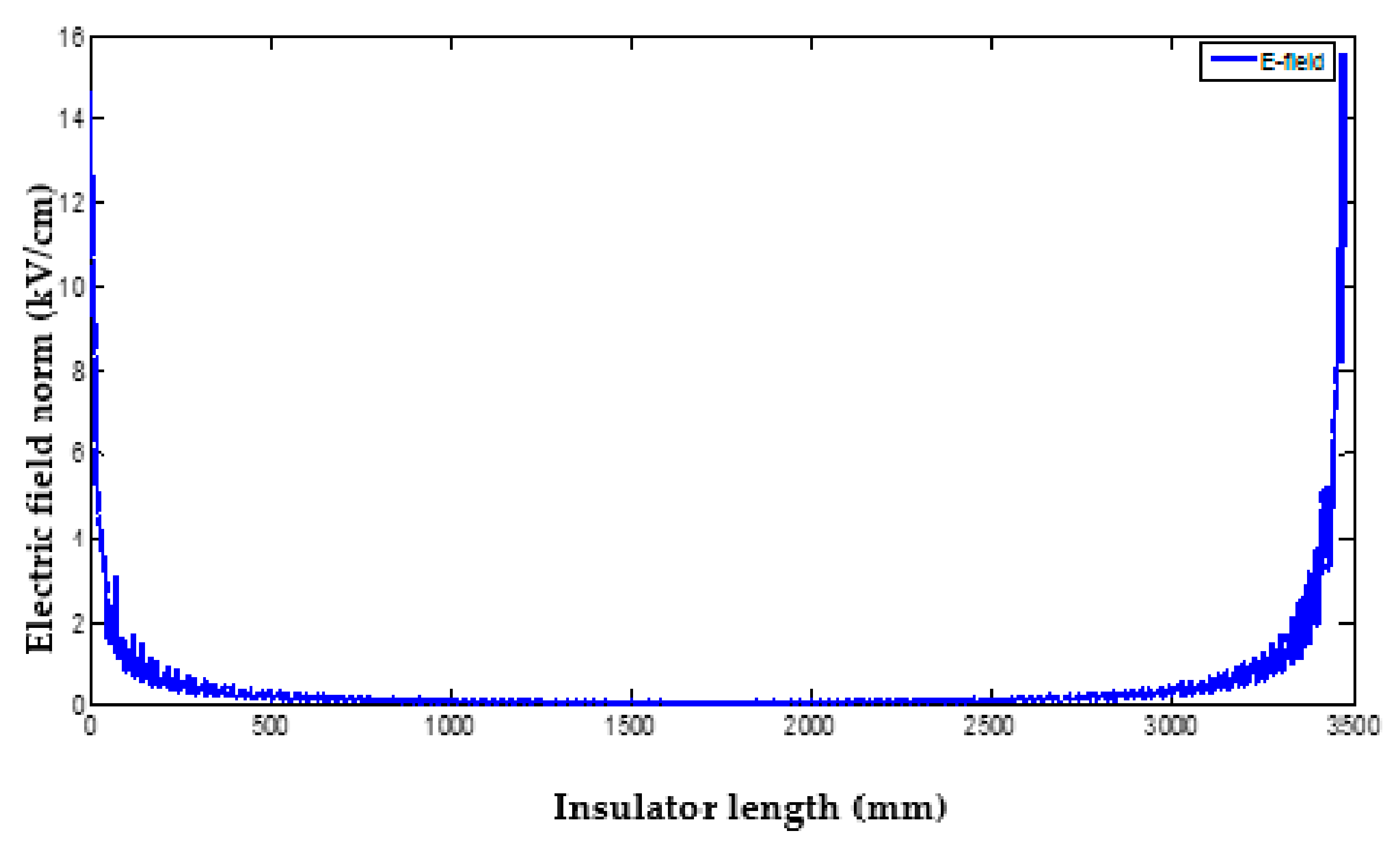
4.1. Electric Field Distribution around Sheds with and without a Grading Ring
Figure 5 illustrates the electric field distribution along the surface of the insulator, under dry and humid conditions with a grading ring fixed at the energized end. The observed maximum electric field value on the insulator, in the absence of a grading ring, was determined to be 14.61 kV/cm, as illustrated in
Figure 5.
The presence of a grading ring near the conductor significantly reduced the maximum electric field value compared to its absence, as depicted in
Figure 6. Specifically, the electric field value was determined to be 1.63 kV/cm when the grading ring was employed, representing only 11.15% of the value observed without the grading ring. This emphasized the crucial role of grading rings in high-voltage transmission lines. Moreover, the assessment of the best grading ring settings was based on the maximum field gradients at the upper regions of the insulator, where the location of the grading ring had the most significant impact.
The simulation results revealed the presence of critical regions near the high-voltage end of the silicone rubber insulator, exhibiting higher field intensities compared to other regions. Consequently, the optimization technique focused on these significant areas to mitigate the overall field strengths associated with them.
Figure 7 illustrates the identified critical regions, marked by 500 mm and 3500 mm cutlines in the 2D representation, originating from above the energized end metal. The utilization of 2D simulations served as the starting point for the investigations, considering that coronas’ starter voltages are influenced by the field distribution across the insulator. The simulations assumed dry and clean surfaces for the insulator during this analysis.
Figure 8 shows the difference between the E-field on the insulator surface with a ring and without a ring.
Figure 9 shows the equipotential lines over the insulator surface which is another technique to illustrate the E-field around the insulator where its highest value causes more lines and more concentration of the E-field near the HV conductor. In this figure (beginning with the HV region) is a zoomed part near the HV conductor.
4.2. Effect of Grading Ring Height (H) on the Electric Field of the Insulator under Study
The values of the maximum E-field were inserted using MATLAB Simulink for the optimization. The grading ring radius R, tube radius r, and vertical height of the grading ring from the triple junction H were the characteristics employed in this study. The placements of R, r, and H on the insulator are depicted in
Figure 1.
Figure 10 depicts the effect of the grading ring vertical height changes on the electric field with a constant grading ring radius of R = 80 and a varying grading ring tube radius. The electric field strength rose as the distance between the grading ring and the high-voltage conductor increased, and as the tube radius increased, the electric field value decreased, but the grading ring radius remained constant at 80 mm in all situations, as can be observed in
Figure 10.
As it can be seen in
Figure 10 and
Figure 11 and
Table A1, the maximum value reached 4.23 kV/cm at R = 80 mm, r = 20 mm, and H = 130 mm, which was the worst case for the curve representing the values of R, r, and H, respectively. The minimum amount of the electric field was 2.60 kV/cm, as it is shown in
Figure 12. The comprehensive results obtained from the study were compiled and are presented in tables in
Appendix A. It is important to note that this case study primarily emphasized the modeling and design aspects, with the collected data intended to support future simulation investigations. These results can be utilized as a foundation for conducting laboratory experiments, which would serve as a means of validation and further enhance the credibility of the simulation findings. The optimal configuration, yielding favorable results, was achieved when the dimensions of the insulator, denoted as R, r, and H, were set to 80 mm, 40 mm, and 130 mm, respectively. This optimal case is illustrated in
Figure 12 and detailed in
Table A1. Furthermore, it is observed that the electric field magnitude increased with an increase in H. The highest electric field value was obtained when H was set to 130 mm and r was set to 40 mm, while R remained at 80 mm, resulting in the optimal electric field distribution for the given system.
A similar investigation was conducted while maintaining a constant grading ring radius of R = 100 mm but varying both the tube radius and the vertical height. The corresponding results are presented in
Figure 13 and
Table A2 in
Appendix A. It is evident from the figure and table that in all examined scenarios, the utilization of grading rings consistently led to a noticeable reduction in the maximum field strengths as the tube radius and vertical height of the grading ring increased. The highest recorded electric field value was 3.89 kV/cm, as shown in
Figure 13 and
Table A2, obtained with parameters R = 100 mm, r = 20 mm, and H = 130 mm, representing the worst-case scenario for the calculations in this study. Conversely, the lowest observed electric field value was 2.19 kV/cm, achieved with parameters R = 100 mm, r = 40 mm, and H = 110 mm. This is considered as the preferred E-field value identified in this case study. The optimal E-field value was attained at H = 90 mm and r = 29.5 mm. Furthermore, when the grading ring radius was adjusted to 120 mm (as depicted in
Figure 14 and documented in
Table A3), the maximum observed electric field value reached 3.67 kV/cm. This occurred with R = 120 mm, r = 20 mm, and H = 130 mm, which represented the worst-case scenario for the calculations in this study (see
Figure 14 and
Table A3 in
Appendix A).
Figure 15 depicts an additional scenario with a grading ring radius of 140 mm. The corresponding results can be found in
Figure 15 and
Table A4 in
Appendix A. It is evident from the figure and table that the maximum electric field value observed was 3.54 kV/cm. This value was obtained with R = 140 mm, r = 20 mm, and H = 130 mm. Conversely, the minimum electric field value was 1.63 kV/cm, as shown in
Figure 15 and documented in
Table A4. This value was achieved with parameters R = 140 mm, r = 40 mm, and H = 90 mm.
The simulation results obtained when the grading ring radius was further increased to 160 mm are presented in
Figure 16 and
Table A5. Notably, the maximum electric field value recorded in that case was 3.45 kV/cm, as illustrated in the figure and table. This value corresponded to the parameters R = 160 mm, r = 20 mm, and H = 130 mm, representing the worst-case scenario. Conversely, the minimum electric field value attained was 1.64 kV/cm, as demonstrated in the same figure and documented in
Table A5. This value was obtained with parameters R = 160 mm, r = 40 mm, and H = 70 mm.
4.3. Effect of the Grading Ring Radius (R) on the Maximum Electric Field of the Insulator under Study
Figure 17 and
Table A6 in
Appendix A provide insights into the behavior of the electric field. The maximum observed value of the electric field was 3.22 kV/cm, as depicted in the figure and documented in
Table A6. This maximum value was reached when the grading ring radius (R) was set to 160 mm, with corresponding values of r = 20 mm and H = 50 mm. This particular configuration represented the worst-case scenario
for the given grading ring radius. Conversely, the minimum electric field value recorded was 1.68 kV/cm, as indicated in
Figure 17 and documented in
Table A6. This minimum value was obtained with R = 140 mm, r = 40 mm, and H = 50 mm. The data collected in
Table A6 provide detailed information on the variation of the electric field as R changed within the range of 80–160 mm, while H 15 remained fixed at 50 mm.
Figure 18, along with the corresponding data in
Table A7, demonstrates the variation of the electric field on the surface of the insulator when the vertical height (H) was adjusted to 70 mm. The maximum recorded value of the electric field reached 3.13 kV/cm, as indicated in
Figure 18 and summarized in
Table A7. This maximum value corresponded to the configuration where the grading ring radius (R), the radius of the tube (r), and the vertical height (H) were set to 160 mm, 20 mm, and 70 mm, respectively. This particular combination was considered the worst-case scenario. Conversely, the minimum electric field value observed was 1.64 kV/cm, occurring when R = 160 mm, r = 40 mm, and H = 70 mm. These findings are presented in
Figure 18 and documented in
Table A7.
Figure 19, in conjunction with
Table A8 in
Appendix A, presents the investigation of the electric field behavior when the vertical height (H) was set to 90 mm. The maximum recorded electric field value was 3.15 kV/cm, occurring in the configuration with 160–20–90 mm. This particular combination was considered the worst-case scenario within this study. Conversely, the minimum electric field value observed was 1.63 kV/cm, which happened when the parameters were set to 140–40–90 mm, as demonstrated in
Figure 19 and documented in
Table A8. Moreover,
Figure 20 and
Table A9 highlight the variation of the maximum electric field value when H was adjusted to 110 mm, while the grading ring radius (R) ranged from 80 mm to 160 mm. The maximum electric field value recorded was 3.64 kV/cm, occurring in the configuration with 80–20–110 mm. This particular combination was considered the worst-case scenario within this investigation. On the other hand, the minimum electric field value obtained was 1.79 kV/cm, which occurred with the parameters set to 140–40–110 mm, as illustrated in
Figure 20 and presented in
Table A9.
When the vertical height (H) was adjusted to 130 mm, the maximum electric field value was observed to be 4.23 kV/cm, as depicted in
Figure 21 and documented in
Table A10. This value was obtained with the parameter configuration of 80–20–130 mm, representing the worst-case scenario in this particular case study. Conversely, the minimum electric field value recorded was 2.04 kV/cm, occurring with the parameters set to 160–40–130 mm, as illustrated in
Figure 21 and presented in
Table A10.
5. Discussion of the Obtained Results
From the obtained results of the E-field calculations on the surface of the insulator with and without the use of a grading ring, it was observed that the absence of a grading ring increased the electric field to 14.61 kV/cm. With the use of a grading ring, that value reached 1.63 kV/cm. It was about 11.15% of its value without using the grading ring, i.e., the drop in the electric field from 14.61 kV/cm to 1.63 kV/cm when using the grading ring represented a reduction of approximately 88.9% in our best-case scenario.
Figure 10,
Figure 11,
Figure 12,
Figure 13,
Figure 14,
Figure 15 and
Figure 16 depict the impact of varying the height (H) of the grading ring on the electric field of the studied insulator. It is evident from these figures that increasing the height of the grading ring led to an increase in the electric field. The optimum configuration was achieved for R = 140 mm, r = 40 mm, and H = 90 mm, resulting in a maximum electric field value of 1.63 kV/cm. These dimensions serve as a useful reference for investigating the influence of grading rings on the distribution of electric field over polluted insulator surfaces.
Figure 17,
Figure 18,
Figure 19,
Figure 20 and
Figure 21 illustrate the effect of the grading ring radius (R) on the maximum electric field of the insulator under study. The figures clearly demonstrated that as the grading ring radius (R) increased, the electric field decreased. The optimal scenario occurred at R = 140 mm, r = 40 mm, and H = 90 mm. These findings aligned with the calculations conducted to examine the impact of the grading ring height on the distribution of the electric field. Additionally, it was observed that when R = 160 mm, r = 40 mm, and H = 70 mm, the maximum electric field value on the insulator surface was 1.64 kV/cm, which was very close to the electric field value of the first case (R = 140 mm, r = 40 mm, and H = 90 mm). Thus, a difference of 20 mm in the grading ring height did not result in a significant change in the electric field. The maximum electric field values of 1.63 kV/cm and 1.64 kV/cm were obtained for R = 140 mm, r = 40 mm, and H = 90 mm, and R = 160 mm, r = 40 mm, and H = 70 mm, respectively. In the following, we present some comparison between our obtained results and recent findings from the literature to further evaluate our results in the context of existing research.
In a recent study [
29], a similar approach combining a finite element method (FEM) and a design of experiments (DOE) approach was employed to optimize the geometry of the corona ring used in composite insulators. The main objective of that optimization was to minimize the maximum electric field (E-field) value. The results demonstrated a significant reduction of 71.5% in the maximum E-field value compared to the case without a corona ring. This finding highlighted the effectiveness of the FEM-DOE methodology in achieving the desired objective of minimizing the E-field for composite insulators. The agreement of our simulation results with those of that study [
29] further supports the validity and detailed nature of our model. However, it is important to note that the lack of an appropriate measurement device hinders a direct experimental validation. Nevertheless, our simulation approach provides a cost-effective means of optimizing the corona ring geometry. Further experiments should be conducted in the future to enhance the validation process and refine the simulation model.
Our research findings are also consistent with the results obtained by Jin Hong and Chen Hong in their study [
29], where they utilized the finite element method (FEM) analysis with the bat optimization method implemented in COMSOL Multi-physics software to investigate the impact of installing a corona ring on the 220 kV composite insulator given in [
21]. They observed a significant improvement in the electric field, with a reduction of approximately 58.6% compared to the threshold value. This demonstrated the effectiveness of the bat algorithm as a novel approach for designing corona rings on composite insulators in power transmission lines, providing more accurate solutions for corona discharge issues. The authors determined the maximum E-field values to be 6.93 kV/cm and 2.68 kV/cm for situations without a corona ring and with the suggested corona ring at the same applied voltage of 180 kV, respectively. With their optimized corona ring design, the maximum E-field was reduced to 1.74 kV/cm.
Regarding our own study, we investigated the optimization of corona rings using a simpler exhaustive search approach instead of bat metaheuristic search, which requires field experts to set up and may be stuck in local optima due to its early fast convergence properties. Thus, a simpler approach proves to be highly competitive as modern powerful computers can easily perform the required calculations. The other advantage of our approach is that its geometry design does not require real-time processing, making it a cost-effective solution.
Furthermore, for a more comprehensive comparison of our results, we considered the study conducted by Aramugam et al. [
33], where they utilized COMSOL Multi-physics software version 4.3 along with a grey wolf optimization (GWO) and an imperialist competitive algorithm (ICA) implemented in MATLAB software for a 132 kV composite insulator. In their investigation, the electric field was individually calculated for varying values of R, r, and H, while maintaining the other parameters constant. Notably, they discovered the optimal dimensions for the corona ring to be R = 82.181 mm, r = 24.897 mm, and H = 20.978 mm, resulting in the lowest simulated electric field of 3.724 kV/cm [
33].
Additionally, in another relevant work by Terrab et al. [
34], the maximum E-field value was achieved through an RSM optimization. They identified the ideal specifications for the corona ring as a radius of 150 mm, a projection from the end fitting of 227 mm, and a ring tube thickness of 90 mm. However, it is important to note that their findings were limited to dry conditions. Notably, their optimized corona ring design yielded a significantly lower maximum E-field of 2.25 kV/cm, which was well below the recommended E-field threshold of 46.4%. This implied that properly constructed corona rings could enhance the insulator’s ability to withstand higher voltages or potentially reduce the size of such insulators. Furthermore, these values remained below the recommended maximum E-field thresholds of 4.2 kV/cm by the EPRI (Electric Power Research Institute) and 4.5 kV/cm by the IEEE (Institute of Electrical and Electronics Engineers) [
34].
The dimensions obtained for the grading ring design, as reported in [
29,
33,
34,
35,
36], can be considered as optimized values. It is important to note that these values represent custom cases and should be regarded as recommendations in view of the lack of a general method or universal standard.
The consistency between our findings and those presented in [
28,
29] and by Aramugam [
33,
34] further validates the reliability of our simulation. These studies collectively support the effectiveness of grading rings in improving the performance of polymeric insulators. However, it is worth emphasizing that our case study results suggest a range of optimal parameter settings collected in
Appendix A, accommodating the specifications and requirements of different industrial applications. This flexibility allows industrial users to customize their setups in a cost-effective manner while complying with the recommendations set forth by the IEEE and the EPRI.
6. Conclusions
In conclusion, our study provided a comprehensive analysis of the optimal design of grading rings for high-voltage, 220 kV polymeric insulators by using an exhaustive search approach. Through the utilization of the finite element method (FEM) and the COMSOL Multi-Physics program for constructing a realistic model, we investigated the influence of the grading ring design parameters on the distribution of the electric field.
Our findings revealed that the absence of a grading ring significantly increased the electric field, reaching a value of 14.61 kV/cm. However, with the implementation of a grading ring, the electric field was reduced to 1.63 kV/cm, representing only 11.15% of the value observed without the grading ring. This remarkable reduction underscores the importance of installing grading rings on high-voltage lines, as they can effectively mitigate the electric field levels.
Furthermore, our study highlighted the optimized dimensions for grading ring design, specifically R = 140 mm, r = 40 mm, and H = 90 mm, which resulted in a minimum electric field value of 1.63 kV/cm. Comparing these results with those of the existing literature, our minimum electric field values were outstanding, demonstrating the efficacy of our approach.
However, it is important to note that our study also yielded a maximum electric field value that was relatively higher compared to the results published in the literature. This discrepancy indicates the need for a further investigation and optimization to ensure that the maximum electric field remains within acceptable limits.
We would like to emphasize that our exhaustive search approach, although simpler than metaheuristic search algorithms, offers a competitive alternative. It does not require advanced mathematical skills and avoids convergence problems often encountered with other optimization techniques. This makes our approach suitable for offline geometric design, where it is essential to find a compromise in favor of accuracy, while higher computational demands are easily satisfied by modern computers.
In addition, the comprehensive results presented in our appendix serve as a valuable “lookup table” for practitioners in the field. These results enable practitioners to easily identify the optimal grading ring design parameters based on their specific needs and requirements. This user-friendly resource assists in streamlining the decision-making process and facilitates the implementation of cost-effective and efficient solutions.
Importantly, all the results obtained in our study comply with the recommendations set forth by the IEEE and the EPRI, making them acceptable and reliable for practical applications in the industry.
In conclusion, our research provides valuable insights into the optimization of grading rings for high-voltage polymeric insulators. While our study demonstrates outstanding minimum electric field values, further investigation is required to optimize the maximum electric field. The competitive nature of our exhaustive search approach, combined with the practicality of our results in the form of an appendix, makes our findings applicable and beneficial for industry practitioners. These findings not only contribute to the existing body of knowledge but also assist in the development of efficient solutions for high-voltage power transmission systems in accordance with industry standards. To sum up, in this research, an attempt was made to provide valuable insights into the impact of grading ring design parameters on the electric field distribution, which can inform future optimization efforts and aid in the development of more effective solutions for ensuring the reliable and efficient operation of high-voltage power transmission systems. We intend to conduct experimental studies to investigate the effect of the mentioned parameters on the electric field in laboratories.
Author Contributions
Conceptualization, E.A.; Methodology, E.A. and F.A.; Validation, E.A., F.A., H.A. and A.D.; Formal analysis, E.A, F.A. and H.A.; Investigation, E.A.; Writing—original draft, E.A. and A.D.; Writing—review & editing, E.A. and A.D.; Supervision, A.D.; Funding acquisition, A.D. All authors have read and agreed to the published version of the manuscript.
Funding
This research received no external funding.
Data Availability Statement
Data is contained within the article or
Appendix A.
Acknowledgments
The Authors gratefully acknowledge the support provided by the Széchenyi István University, Győr, Hungary.
Conflicts of Interest
The authors declare no conflict of interest.
Appendix A
Table A1.
Values of the maximum electric field on the insulator surface for a corona ring design with R = 80 mm, a variable r, and a variable H.
Table A1.
Values of the maximum electric field on the insulator surface for a corona ring design with R = 80 mm, a variable r, and a variable H.
| Electric Field with the Change of the Height of the Corona Ring from the Triple Junction at a Tube Radius of 20 mm | Electric Field with the Change of the Height of the Corona Ring from the Triple Junction at a Tube Radius of 25 mm | Electric Field with the Change of the Height of the Corona Ring from the Triple Junction at a Tube Radius of 30 mm | Electric Field with the Change of the Height of the Corona Ring from the Triple Junction at a Tube Radius of 35 mm | Electric Field with the Change of the Height of the Corona Ring from the Triple Junction at a Tube Radius of 40 mm |
|---|
| 80–20–50 max E-field is 2.76 kV/cm | 80–20–50 max E-field is 2.76 kV/cm | 80–30–50 max E-field is 2.74 kV/cm | 80–35–50 max E-field is 2.71 kV/cm | 80–40–50 max E-field is 2.66 kV/cm |
| 80–20–70 max E-field is 2.78 kV/cm | 80–25–70 max E-field is 2.79 kV/cm | 80–30–70 max E-field is 2.78 kV/cm | 80–35–70 max E-field is 2.73 kV/cm | 80–40–70 max E-field is 2.69 kV/cm |
| 80–20–90 max E-field is 3.08 kV/cm | 80–25–90 max E-field is 2.75 kV/cm | 80–30–90 max E-field is 2.69 kV/cm | 80–35–90 max E-field is 2.64 kV/cm | 80–40–90 max E-field is 2.61 kV/cm |
| 80–20–110 max E-field is 3.64 kV/cm | 80–25–110 max E-field is3.10 kV/cm | 80–30–110 max E-field is 2.72 kV/cm | 80–35–110 max E-field is 2.70 kV/cm | 80–40–110 max E-field is 2.66 kV/cm |
| 80–20–130 max E-field is 4.23 kV/cm | 80–25–130 max E-field is 3.71 kV/cm | 80–30–130max E-field is 3.25 kV/cm | 80–35–130 max E-field is 2.85 kV/cm | 80–40–130 max E-field is 2.60 kV/cm |
Table A2.
Values of the maximum electric field on the insulator surface for a corona ring design with R = 100 mm, a variable r, and a variable H.
Table A2.
Values of the maximum electric field on the insulator surface for a corona ring design with R = 100 mm, a variable r, and a variable H.
| Electric Field with the Change of the Height of the Corona Ring from the Triple Junction at a Tube Radius of 20 mm | Electric Field with the Change of the Height of the Corona Ring from the Triple Junction at a Tube Radius of 25 mm | Electric Field with the Change of the Height of the Corona Ring from the Triple Junction at a Tube Radius of 30 mm | Electric Field with the Change of the Height of the Corona Ring from the Triple Junction at a Tube Radius of 35 mm | Electric Field with the Change of the Height of the Corona Ring from the Triple Junction at a Tube Radius of 40 mm |
|---|
| 100–20–50, max E-field is 2.69 kV/cm | 100–25–50, max E-field is 2.34 kV/cm | 100–30–50 max E-field is 2.32 kV/cm | 100–35–50 max E-field is 2.30 kV/cm | 100–40–50 max E-field is 2.27 kV/cm |
| 100–20–70 max E-field is 2.76 kV/cm | 100–25–70 max E-field is 2.33 kV/cm | 100–30–70 max E-field is 2.31 kV/cm | 100–35–70 max E-field is 2.26 kV/cm | 100–40–70 max E-field is 2.21 kV/cm |
| 100–20–90 max E-field is 3.04 kV/cm | 100–25–90 max E-field is 2.51 kV/cm | 100–30–90 max E-field is 2.24 kV/cm | 100–35–90 max E-field is 2.23 kV/cm | 100–40–90 max E-field is 2.22 kV/cm |
| 100–20–110 max E-field is 3.44 kV/cm | 100–25–110 max E-field is 2.92 kV/cm | 100–30–110 max E-field is 2.49 kV/cm | 100–35–110 max E-field is 2.23 kV/cm | 100–40–110 max E-field is 2.19 kV/cm |
| 100–20–130 max E-field is 3.89 kV/cm | 100–25–130 max E-field is 3.39 kV/cm | 100–30–130 max E-field is 2.97 kV/cm | 100–35–130 max E-field is 2.60 kV/cm | 100–40–130 max E-field is 2.27 kV/cm |
Table A3.
Values of the maximum electric field on the insulator surface for a corona ring design with R = 120 mm, a variable r, and a variable H.
Table A3.
Values of the maximum electric field on the insulator surface for a corona ring design with R = 120 mm, a variable r, and a variable H.
| Electric Field with the Change of the Height of the Corona Ring from the Triple Junction at a Tube Radius of 20 mm | Electric Field with the Change of the Height of the Corona Ring from the Triple Junction at a Tube Radius of 25 mm | Electric Field with the Change of the Height of the Corona Ring from the Triple Junction at a Tube Radius of 30 mm | Electric Field with the Change of the Height of the Corona Ring from the Triple Junction at a Tube Radius of 35 mm | Electric Field with the Change of the Height of the Corona Ring from the Triple Junction at a Tube Radius of 40 mm |
|---|
| 120–20–50 max E-field is 2.92 kV/cm | 120–25–50 max E-field is 2.39 kV/cm | 120–30–50 max is 2.00 kV/cm | 120–35–50 max is 1.97 kV/cm | 120–40–50 max is 1.94 kV/cm |
| 120–20–70 max E-field is 2.90 kV/cm | 120–25–70 max E-field is 2.39 kV/cm | 120–30–70 max E-field is 1.96 kV/cm | 120–35–70 max E-field is 1.90 kV/cm | 120–40–70 max E-field is 1.88 kV/cm |
| 120–20–90 max E-field is 3.06 kV/cm | 120–25–90 max E-field is 2.56 kV/cm | 120–30–90 max E-field is 2.14 kV/cm | 120–35–90 max E-field is 1.92 kV/cm | 120–40–90 max E-field is 1.90 kV/cm |
| 120–20–110 max E-field is 3.33 kV/cm | 120–25–110 max E-field is 2.84 kV/cm | 120–30–110 max E-field is 2.43 kV/cm | 120–35–110 max E-field is 2.08 kV/cm | 120–40–110 max E-field is 1.86 kV/cm |
| 120–20–130 max E-field is 3.67 kV/cm | 120–25–130 max E-field is 3.20 kV/cm | 120–30–130 max E-field is 2.80 kV/cm | 120–35–130 max E-field is 2.44 kV/cm | 120–40–130 max E-field is 2.13 kV/cm |
Table A4.
Values of the maximum electric field on the insulator surface for a corona ring design with R = 140 mm, a variable r, and a variable H.
Table A4.
Values of the maximum electric field on the insulator surface for a corona ring design with R = 140 mm, a variable r, and a variable H.
| Electric Field with the Change of the Height of the Corona Ring from the Triple Junction at a Tube Radius of 20 mm | Electric Field with the Change of the Height of the Corona Ring from the Triple Junction at a Tube Radius of 25 mm | Electric Field with the Change of the Height of the Corona Ring from the Triple Junction at a Tube Radius of 30 mm | Electric Field with the Change of the Height of the Corona Ring from the Triple Junction at a Tube Radius of 35 mm | Electric Field with the Change of the Height of the Corona Ring from the Triple Junction at a Tube Radius of 40 mm |
|---|
| 140–20–50 max E-field is 3.09 kV/cm | 140–25–50 max E-field is 2.59 kV/cm | 140–30–50 max E-field is 2.17 kV/cm | 140–35–50 max E-field is 1.82 kV/cm | 140–40–50 max E-field is 1.70 kV/cm |
| 140–20–70 max E-field is 3.02 kV/cm | 140–25–70 max E-field is 2.53 kV/cm | 140–30–70 max E-field is 2.12 kV/cm | 140–35–70 max E-field is 1.84 kV/cm | 140–40–70 max E-field is 1.66 kV/cm |
| 140–20–90 max E-field is 3.10 kV/cm | 140–25–90 max E-field is 2.62 kV/cm | 140–30–90 max E-field is 2.22 kV/cm | 140–35–90 max E-field is 1.88 kV/cm | 140–40–90 max E-field is 1.63 kV/cm |
| 140–20–110 max E-field is 3.28 kV/cm | 140–25–110 max E-field is 2.82 kV/cm | 140–30–110 max E-field is 2.42 kV/cm | 140–35–110 max E-field is 2.08 kV/cm | 140–40–110 max E-field is 1.79 kV/cm |
| 140–20–130 max E-field is 3.54 kV/cm | 140–25–130 max E-field is 3.08 kV/cm | 140–30–130 max E-field is 2.70 kV/cm | 140–35–130 max E-field is 2.36 kV/cm | 140–40–130 max E-field is 2.06 kV/cm |
Table A5.
Values of the maximum electric field on the insulator surface for a corona ring design with R = 160 mm, a variable r, and a variable H.
Table A5.
Values of the maximum electric field on the insulator surface for a corona ring design with R = 160 mm, a variable r, and a variable H.
| Electric Field with the Change of the Height of the Corona Ring from the Triple Junction at a Tube Radius of 20 mm | Electric Field with the Change of the Height of the Corona Ring from the Triple Junction at a Tube Radius of 25 mm | Electric Field with the Change of the Height of the Corona Ring from the Triple Junction at a Tube Radius of 30 mm | Electric Field with the Change of the Height of the Corona Ring from the Triple Junction at a Tube Radius of 35 mm | Electric Field with the Change of the Height of the Corona Ring from the Triple Junction at a Tube Radius of 40 mm |
|---|
| 160–20–50 max E-field is 3.22 kV/cm | 160–25–50 max E-field is 2.74 kV/cm | 160–30–50 max E-field is 2.34 kV/cm | 160–35–50 max E-field is 2.00 kV/cm | 160–40–50 max E-field is 1.70 kV/cm |
| 160–20–70 max E-field is 3.13 kV/cm | 160–25–70 max E-field is 2.66 kV/cm | 160–30–70 max E-field is 2.27 kV/cm | 160–35–70 max E-field is 1.93 kV/cm | 160–40–70 max E-field is 1.64 kV/cm |
| 160–20–90 max E-field is 3.15 kV/cm | 160–25–90 max E-field is 2.69 kV/cm | 160–30–90 max E-field is 2.31 kV/cm | 160–35–90 max E-field is 1.98 kV/cm | 160–40–90 max E-field is 1.69 kV/cm |
| 160–20–110 max E-field is 3.27 kV/cm | 160–25–110 max E-field is 2.82 kV/cm | 160–30–110 max E-field is 2.44 kV/cm | 160–35–110 max E-field is 2.11 kV/cm | 160–40–110 max E-field is 1.83 kV/cm |
| 160–20–130 max E-field is 3.45 kV/cm | 160–25–130 max E-field is 3.01 kV/cm | 160–30–130 max E-field is 2.64 kV/cm | 160–35–130 max E-field is 2.32 kV/cm | 160–40–130 max E-field is 2.04 kV/cm |
Table A6.
Values of the maximum electric field on the insulator surface for a constant corona ring with a height H = 50 mm, a variable r, and a variable R.
Table A6.
Values of the maximum electric field on the insulator surface for a constant corona ring with a height H = 50 mm, a variable r, and a variable R.
| Max Value of the E-Field with the Change of the Corona Ring Radius and Fixing Its Height from the Triple Junction at a Tube Radius of 20 mm | Max Value of the E-Field with the Change of the Corona Ring Radius and Fixing Its Height from the Triple Junction at a Tube Radius of 25 mm | Max Value of the E-Field with the Change of the Corona Ring Radius and Fixing Its Height from the Triple Junction at a Tube Radius of 30 mm | Max Value of the E-Field with the Change of the Corona Ring Radius and Fixing Its Height from the Triple Junction at a Tube Radius of 35 mm | Max Value of the E-Field with the Change of the Corona Ring Radius and Fixing Its Height from the Triple Junction at a Tube Radius of 40 mm |
|---|
| 80–20–50 max E-field is 2.76 kV/cm | 80–20–50 max E-field is 2.76 kV/cm | 80–30–50 max E-field is 2.74 kV/cm | 80–35–50 max E-field is 2.71 kV/cm | 80–40–50 max E-field is 2.66 kV/cm |
| 100–20–50 max E-field is 2.69 kV/cm | 100–25–50 max E-field is 2.34 kV/cm | 100–30–50 max is 2.32 kV/cm | 100–35–50 max E-field is 2.30 kV/cm | 100–40–50 max E-field is 2.27 kV/cm |
| 120–20–50 max E-field is 2.92 kV/cm | 120–25–50 max E-field is 2.39 kV/cm | 120–30–50 max E-field is 2.00 kV/cm | 120–35–50 max E-field is 1.97 kV/cm | 120–40–50 max E-field is 1.94 kV/cm |
| 140–20–50 max E-field is 3.09 kV/cm | 140–25–50 max E-field is 2.59 kV/cm | 140–30–50 max E-field is 2.17 kV/cm | 140–35–50 max E-field is 1.82 kV/cm | 140–40–50 max E-field is 1.68 kV/cm |
| 160–20–50 max E-field is 3.22 kV/cm | 160–25–50 max E-field is 2.74 kV/cm | 160–30–50 max E-field is 2.34 kV/cm | 160–35–50 max E-field is 2.00 kV/cm | 160–40–50 max E-field is 1.70 kV/cm |
Table A7.
Values of the maximum electric field on the insulator surface for a constant corona ring with a height H = 70 mm, a variable r, and a variable R.
Table A7.
Values of the maximum electric field on the insulator surface for a constant corona ring with a height H = 70 mm, a variable r, and a variable R.
| Max Value of the E-Field with the Change of the Corona Ring Radius and Fixing Its Height from the Triple Junction at a Tube Radius of 20 mm | Max Value of the E-Field with the Change of the Corona Ring Radius and Fixing Its Height from the Triple Junction at a Tube Radius of 25 mm | Max Value of the E-Field with the Change of the Corona Ring Radius and Fixing Its Height from the Triple Junction at a Tube Radius of 30 mm | Max Value of the E-Field with the Change of the Corona Ring Radius and Fixing Its Height from the Triple Junction at a Tube Radius of 35 mm | Max Value of the E-Field with the Change of the Corona Ring Radius and Fixing Its Height from the Triple Junction at a Tube Radius of 40 mm |
|---|
| 80–20–70, max E-field is 2.78 kV/cm | 80–25–70 max E-field is 2.79 kV/cm | 80–30–70 max E-field is 2.78 kV/cm | 80–35–70 max E-field is 2.73 kV/cm | 80–40–70 max E-field is 2.69 kV/cm |
| 100–20–70, max E-field is 2.76 kV/cm | 100–25–70 max E-field is 2.33 kV/cm | 100–30–70 max E-field is 2.31 kV/cm | 100–35–70 max is 2.26 kV/cm | 100–40–70 max E-field is 2.21 kV/cm |
| 120–20–70 max E-field is 2.90 kV/cm | 120–25–70 max E-field is 2.39 kV/cm | 120–30–70 max E-field is 1.96 kV/cm | 120–35–70 max E-field is 1.90 kV/cm | 120–40–70 max E-field is 1.88 kV/cm |
| 140–20–70 max E-field is 3.02 kV/cm | 140–25–70 max E-field is 2.53 kV/cm | 140–30–70 max is 2.12 kV/cm | 140–35–70 max E-field is 1.84 kV/cm | 140–40–70 max E-field is 1.66 kV/cm |
| 160–20–70 max E-field is 3.13 kV/cm | 160–25–70 max E-field is 2.66 kV/cm | 160–30–70 max E-field is 2.27 kV/cm | 160–35–70 max E-field is 1.93 kV/cm | 160–40–70 max E-field is 1.64 kV/cm |
Table A8.
Values of the maximum electric field on the insulator surface for a constant corona ring with a height H = 90 mm, a variable r, and a variable R.
Table A8.
Values of the maximum electric field on the insulator surface for a constant corona ring with a height H = 90 mm, a variable r, and a variable R.
| Max Value of the E-Field with the Change of the Corona Ring Radius and Fixing Its Height from the Triple Junction at a Tube Radius of 20 mm | Max Value of the E-Field with the Change of the Corona Ring Radius and Fixing Its Height from the Triple Junction at a Tube Radius of 25 mm | Max Value of the E-Field with the Change of the Corona Ring Radius and Fixing Its Height from the Triple Junction at a Tube Radius of 30 mm | Max Value of the E-Field with the Change of the Corona Ring Radius and Fixing Its Height from the Triple Junction at a Tube Radius of 35 mm | Max Value of the E-Field with the Change of the Corona Ring Radius and Fixing Its Height from the Triple Junction at a Tube Radius of 40 mm |
|---|
| 80–20–90, max E-field is 3.08 kV/cm | 80–25–90 max E-field is 2.75 kV/cm | 80–30–90 max E-field is 2.69 kV/cm | 80–35–90 max E-field is 2.64 kV/cm | 80–40–90 max E-field is 2.61 kV/cm |
| 100–20–90 max E-field is 3.04 kV/cm | 100–25–90 max E-field is 2.51 kV/cm | 100–30–90 max E-field is 2.24 kV/cm | 100–35–90 max E-field is 2.23 kV/cm | 100–40–90 max E-field is 2.22 kV/cm |
| 120–20–90 max E-field is 3.06 kV/cm | 120–25–90 max E-field is 2.56 kV/cm | 120–30–90 max E-field is 2.14 kV/cm | 120–35–90 max E-field is 1.92 kV/cm | 120–40–90 max E-field is 1.90 kV/cm |
| 140–20–90 max E-field is 3.10 kV/cm | 140–25–90 max E-field is 2.62 kV/cm | 140–30–90 max E-field is 2.22 kV/cm | 140–35–90 max E-field is 1.88 kV/cm | 140–40–90 max E-field is 1.63 kV/cm |
| 160–20–90 max E-field is 3.15 kV/cm | 160–25–90 max E-field is 2.69 kV/cm | 160–30–90 max E-field is 2.31 kV/cm | 160–35–90 max E-field is 1.98 kV/cm | 160–40–90 max E-field is 1.69 kV/cm |
Table A9.
Values of the maximum electric field on the insulator surface for a constant corona ring with a height H = 110 mm, a variable r, and a variable R.
Table A9.
Values of the maximum electric field on the insulator surface for a constant corona ring with a height H = 110 mm, a variable r, and a variable R.
| Max Value of the E-Field with the Change of the Corona Ring Radius and Fixing Its Height from the Triple Junction at a Tube Radius of 20 mm | Max Value of the E-Field with the Change of the Corona Ring Radius and Fixing Its Height from the Triple Junction at a Tube Radius of 25 mm | Max Value of the E-Field with the Change of the Corona Ring Radius and Fixing Its Height from the Triple Junction at a Tube Radius of 30 mm | Max Value of the E-Field with the Change of the Corona Ring Radius and Fixing Its Height from the Triple Junction at a Tube Radius of 35 mm | Max Value of the E-Field with the Change of the Corona Ring Radius and fixing Its Height from the Triple Junction at a Tube Radius of 40 mm |
|---|
| 80–20–110 max E-field is 3.64 kV/cm | 80–25–110 max E-field is 3.10 kV/cm | 80–30–110 max E-field is 2.72 kV/cm | 80–35–110 max E-field is 2.70 kV/cm | 80–40–110 max E-field is 2.66 kV/cm |
| 100–20–110, max E-field is 3.44 kV/cm | 100–25–110 max E-field is 2.92 kV/cm | 100–30–110 max E-field is 2.49 kV/cm | 100–35–110 max E-field is 2.23 kV/cm | 100–40–110 max E-field is 2.19 kV/cm |
| 120–20–110 max E-field is 3.33 kV/cm | 120–25–110 max E-field is 2.84 kV/cm | 120–30–110 max E-field is 2.43 kV/cm | 120–35–110 max E-field is 2.08 kV/cm | 120–40–110 max E-field is 1.86 kV/cm |
| 140–20–110 max E-field is 3.28 kV/cm | 140–25–110 max E-field is 2.82 kV/cm | 140–30–110 max E-field is 2.42 kV/cm | 140–35–110 max E-field is 2.08 kV/cm | 140–40–110 max E-field is 1.79 kV/cm |
| 160–20–110 max E-field is 3.27 kV/cm | 160–25–110 max E-field is 2.82 kV/cm | 160–30–110 max E-field is 2.44 kV/cm | 160–35–110 max E-field is 2.11 kV/cm | 160–40–110 max E-field is 1.83 kV/cm |
Table A10.
Values of the maximum electric field on the insulator surface for a constant corona ring with a height H = 130 mm, a variable r, and a variable R.
Table A10.
Values of the maximum electric field on the insulator surface for a constant corona ring with a height H = 130 mm, a variable r, and a variable R.
| Max Value of the E-Field with the Change of the Corona Ring Radius and Fixing Its Height from the Triple Junction at a Tube Radius of 20 mm | Max Value of the E-Field with the Change of the Corona Ring Radius and Fixing Its Height from the Triple Junction at a Tube Radius of 25 mm | Max Value of the E-Field with the Change of the Corona Ring Radius and fixing Its Height from the Triple Junction at a Tube Radius of 30 mm | Max Value of the E-Field with the Change of the Corona Ring Radius and fixing Its Height from the Triple Junction at a Tube Radius of 35 mm | Max Value of the E-Field with the Change of the Corona Ring Radius and fixing Its Height from the Triple Junction at a Tube Radius of 40 mm |
|---|
| 80–20–130 max E-field is 4.23 kV/cm | 80–25–130 max E-field is 3.71 kV/cm | 80–30–130 max E-field is 3.25 kV/cm | 80–35–130 max E-field is 2.85 kV/cm | 80–40–130 max E-field is 2.60 kV/cm |
| 100–20–130 max E-field is 3.89 kV/cm | 100–25–130 max E-field is 3.39 kV/cm | 100–30–130 max E-field is 2.97 kV/cm | 100–35–130 max E-field is 2.60 kV/cm | 100–40–130 max E-field is 2.27 kV/cm |
| 120–20–130 max E-field is 3.67 kV/cm | 120–25–130 max E-field is 3.20 kV/cm | 120–30–130 max E-field is 2.79 kV/cm | 120–35–130 max E-field is 2.44 kV/cm | 120–40–130 max E-field is 2.13 kV/cm |
| 140–20–130 max E-field is 3.54 kV/cm | 140–25–130 max E-field is 3.08 kV/cm | 140–30–130 max E-field is 2.69 kV/cm | 140–35–130 max E-field is 2.36 kV/cm | 140–40–130 max E-field is 2.06 kV/cm |
| 160–20–130 max E-field is 3.45 kV/cm | 160–25–130 max E-field is 3.01 kV/cm | 160–30–130 max E-field is 2.64 kV/cm | 160–35–130 max E-field is 2.32 kV/cm | 160–40–130 max E-field is 2.04 kV/cm |
References
- Al Murawwi, E.; El-Hag, A. Corona Ring Design for a 400 kV Non-Ceramic Insulator. In Proceedings of the 2nd International Conference on Electric Power and Energy Conversion Systems (EPECS), Sharjah, United Arab Emirates, 15–17 November 2011; pp. 1–4. [Google Scholar] [CrossRef]
- Sima, W.; Espino-Cortes, F.P.; Chemey, E.A.; Jayaram, S.H. Optimization of Corona Ring Design for Long-Rod Insulators Using FEM Based Computational Analysis. In Proceedings of the Conference Record of the 2004 IEEE International Symposium on Electrical Insulation, Indianapolis, IN, USA, 19–22 September 2004; pp. 480–483. [Google Scholar] [CrossRef]
- Farhad, N.; Asaad, S.; Pourya, K. Modeling and Optimization of Dimensions of Corona Rings on High-Voltage Composite Insulators Using FEM. Adv. Sci. Eng. Med. 2020, 12, 1204–1207. [Google Scholar] [CrossRef]
- Sarma Maruvada, P. Corona Performance of High Voltage Transmission Lines, 1st ed.; Research Studies Press Ltd., University of Michigan: Ann Arbor, MI, USA, 2000; ISBN 100863802540. ISBN 13978-0863802546. [Google Scholar]
- Kuffel, E.; Zaengl, W.S.; Kuffel, J. High Voltage Engineering: Fundamentals, 2nd ed.; Butterworth-Heinemann: Oxford, UK, 2000; ISBN 0-7506-3634-3. [Google Scholar]
- Daochun, H.; Jiangjun, R.; Yong, C.; Feng, H.; Shifeng, Y.; Shoubao, L. Calculation and measurement of potential and electric field distribution along 1000 kV AC transmission line composite insulator. In Proceedings of the 2008 International Conference on Electrical Machines and Systems, Wuhan, China, 17–20 October 2008; pp. 428–433, ISBN 978-1-4244-3826-6. [Google Scholar]
- Sima, W.; Yang, Q.; Sun, C.; Guo, F. Potential and Electric-Field Calculation along an Ice-Covered Composite Insulator with Finite-Element Method. IET Proc. Gener. Transm. Distribution 2006, 153, 343–349. [Google Scholar] [CrossRef]
- Joneidi, I.A.; Shayegani, A.A.; Mohseni, H. Electric Field Distribution Under Water Droplet and Effect of Thickness and Conductivity of Pollution Layer on Polymer Insulators Using Finite Element Method. Int. J. Comput. Electr. Eng. 2013, 5, 266–270. [Google Scholar] [CrossRef] [Green Version]
- Aouabed, F.; Bayadi, A.; Rahmani, A.E.; Boudissa, R. Finite element modeling of electric field and voltage distribution on a silicone insulating surface covered with water droplets. IEEE Trans. Dielectr. Electr. Insul. 2018, 25, 413–420. [Google Scholar] [CrossRef]
- Hamdi, M.; Teguar, M.; Mekhaldi, A. Optimal Design of Grading Ring on HV Composite Insulator Using PSO Approach with Dynamic Population Size. IEEE Trans. Dielectr. Electr. Insul. 2016, 23, 1048–1057. [Google Scholar] [CrossRef]
- Weiguo, Q.; Sebo, S.A. Electric field and potential distributions along dry and clean non-ceramic insulators. In Proceedings of the Electrical Insulation Conference and Electrical Manufacturing and Coil Winding Conference (Cat. No.01CH37264), Cincinnati, OH, USA, 18 October 2001; pp. 437–440. [Google Scholar] [CrossRef]
- Zhao, T.; Comber, M.G. Calculation of electric field and potential distribution along non-ceramic insulators considering the effects of conductors and transmission towers. IEEE Trans. Power Deliv. 2000, 15, 313–318. [Google Scholar] [CrossRef]
- Hussain, M.K.; Alshadeedi, B.M. Optimal design of high voltage composite insulators with grading rings in different configurations. Electr. Power Syst. Res. 2023, 221, 109493. [Google Scholar] [CrossRef]
- Zhang, B.; He, J.; Cui, X.; Han, S.; Zou, J. Electric field calculation for HV insulators on the head of transmission tower by coupling CSM with BEM. IEEE Trans. Magn. 2006, 42, 543–546. [Google Scholar] [CrossRef]
- Sebestyn, I. Electric-field calculation for HV insulators using domain-decomposition method. IEEE Trans. Magn. 2002, 38, 1213–1216. [Google Scholar] [CrossRef]
- Kontargyri, V.T.; Gonos, I.F.; Stathopoulos, I.A.; Michealides, A.M. Simulation of the Electric Field on High Voltage Insulators using the Finite Element Method. In Proceedings of the 2006 12th Biennial IEEE Conference on Electromagnetic Field Computation, Miami, FL, USA, 30 April–3 May 2006; p. 373. [Google Scholar] [CrossRef]
- Iravani, M.R.; Raghuveer, M.R. Numerical Computation of Potential Distribution along a Transmission Line Insulator Chain. IEEE Trans. Electr. Insul. 1983, 18, 167–170. [Google Scholar] [CrossRef]
- Li, J.; Peng, Z.; Feng, Y.; Fu, X.; Xie, T. Electric field calculation and grading ring optimization of composite insulator for 500kV AC transmission lines. In Proceedings of the 2010 10th IEEE International Conference on Solid Dielectrics, Potsdam, Germany, 4–9 July 2010; pp. 1–4. [Google Scholar] [CrossRef]
- Baccouch, M. A Brief Summary of the Finite Element Method for Differential Equations. In Finite Element Methods and Their Applications; IntechOpen: Rijeka, Croatia, 2021. [Google Scholar] [CrossRef]
- Abd Rahman, P. Investigation of ZNO Micro Varistor for Stress Control on Polymeric. Ph.D. Thesis, Cardiff University, Cardiff, UK, 2012. Available online: https://orca.cardiff.ac.uk/38993/1/2012AbdRahmanRPhD.pdf (accessed on 20 February 2023).
- Hong, J.; Hong, C. Electric Field Analysis of 220 kV Composite Rod Insulator. In Proceedings of the 2011 IEEE Power Engineering and Automation Conference, Wuhan, China, 8–9 September 2011; pp. 73–77. [Google Scholar] [CrossRef]
- Composite Insulator-Product Specifications, Phoenix Technology Group Co. Ltd. Available online: http://www.alibaba.com/product-gs/206311888/Composit (accessed on 11 April 2023).
- Marklein, R. The Finite Integration Technique as a General Tool to Compute Acoustic, Electromagnetic, Elasto-Dynamic, and Coupled Wave Fields; IEEE Press: New York, NY, USA, 2002; pp. 201–244. [Google Scholar]
- Weiland, T. A Discretization Method for the Solution of Maxwell’s Equation s for Six-Component Fields; Electronics and Communication (AEU), Darmstadt University of Technology: Darmstadt, Germany, 1977; Volume 31, pp. 116–120. [Google Scholar]
- Naidu, M.S.; Kamaraju, V. High Voltage Engineering, 2nd ed.; MC Grew-Hill: New York, NY, USA, 2009; ISBN 0-07-462286-2. [Google Scholar]
- Benguesmia, H.; M’ziou, N.; Boubakeur, A. Simulation of the potential and electric field distribution on high voltage insulator using the finite element method. Diagnostyka 2018, 19, 41–52. [Google Scholar] [CrossRef]
- Benguesmia, H.; Bakri, B.; Khadar, S.; Hamrit, F.; M’ziou, N. Experimental study of pollution and simulation on insulators using COMSOL® under AC voltage. Diagnostyka 2019, 20, 21–29. [Google Scholar] [CrossRef]
- Ilhan, S.; Ozdemir, A.; Ismailoğlu, H. Impacts of grading rings on the insulation performance of composite polymer insulator strings. IEEE Trans. Dielectr. Electr. Insul. 2015, 22, 1605–1612. [Google Scholar] [CrossRef]
- Belhouchet, K.; Ouchen, L.; Bayadi, A.; Nadjim, A.L. A Novel Application of Artificial Intelligence Technology for Outdoor High-Voltage Composite Insulators. J. Supercomput. 2023. [Google Scholar] [CrossRef]
- Phillips, A.J.; Kuffel, J.; Baker, A.; Burnham, J.; Carreira, A.; Cherney, E.; Chisholm, W.; Farzaneh, M.; Gemignani, R.; Gillespie, A.; et al. Electric fields on AC composite transmission line insulators. IEEE Trans. Power Deliv. 2008, 23, 823–830. [Google Scholar] [CrossRef]
- Phillips, A.; Maxwell, A.; Engelbrecht, C.; Gutman, I. Electric-field limits for the design of grading rings for composite line insulators. IEEE Trans. Power Deliv. 2015, 30, 1110–1118. [Google Scholar] [CrossRef]
- Phillips, A. Electric Field Distribution and Their Impact on Transmission Line Composite Insulators; PES T&D: Orlando, FL, USA, 2012; pp. 1–3. [Google Scholar] [CrossRef]
- Aramugam, K.; Illias, H.A.; Ching, Y.C.; Ali, M.S.; Makmud, M.Z. Optimal Design of Corona Ring for 132 kV Insulator at High Voltage Transmission Lines Based on Optimisation Techniques. Energies 2023, 16, 778. [Google Scholar] [CrossRef]
- Hocine, T.; Kara, A. Parameters design optimization of 230 kV corona ring based on electric field analysis and response surface methodology. Electr. Power Syst. Res. 2018, 163, 782–788. [Google Scholar] [CrossRef]
- Mohammad, S.; Hoseini, H.F.; Mahdi, M.A.; Tavakoli, M. Electric Field Distributions around Silicon Rubber Insulators in Polluted and Cleaned Area. Int. J. Sci. Eng. Investig. 2013, 2, 137–140. [Google Scholar]
- Lalitha, M.; Kumar, K.V.; Samala, V. Design and simulation of voltage and electric field distribution on disc insulators using finite element method in Opera software. In Proceedings of the International Conference on Smart Electric Grid (ISEG), Guntur, India, 19–20 September 2014; pp. 1–6. [Google Scholar] [CrossRef]
Figure 1.
Dimensions details for a long-rod silicone rubber insulator.
Figure 1.
Dimensions details for a long-rod silicone rubber insulator.
Figure 2.
Extremely fine meshes for the used model.
Figure 2.
Extremely fine meshes for the used model.
Figure 3.
Illustration of the methodology of arranging variables for the exhaustive search analysis approach.
Figure 3.
Illustration of the methodology of arranging variables for the exhaustive search analysis approach.
Figure 4.
Two-dimensional axial-symmetric modeling of the polymeric insulator type, 220 kV.
Figure 4.
Two-dimensional axial-symmetric modeling of the polymeric insulator type, 220 kV.
Figure 5.
Electric field distribution along the surface of the insulator, under dry and humid conditions without an existing grading ring.
Figure 5.
Electric field distribution along the surface of the insulator, under dry and humid conditions without an existing grading ring.
Figure 6.
Electric field distribution along the insulator, under dry and clean conditions with an existing grading ring at the energized end.
Figure 6.
Electric field distribution along the insulator, under dry and clean conditions with an existing grading ring at the energized end.
Figure 7.
Two-dimensional cutline from the silicone rubber up to 3500 mm.
Figure 7.
Two-dimensional cutline from the silicone rubber up to 3500 mm.
Figure 8.
Comparison of the electric field along the insulator with and without a ring.
Figure 8.
Comparison of the electric field along the insulator with and without a ring.
Figure 9.
Equipotential lines over the insulator surface.
Figure 9.
Equipotential lines over the insulator surface.
Figure 10.
Effect of H on the maximum electric field of the insulator surface with a constant grading ring radius at R = 80 mm.
Figure 10.
Effect of H on the maximum electric field of the insulator surface with a constant grading ring radius at R = 80 mm.
Figure 11.
Maximum electric field with r = 20 mm, H = 130 mm, and R = 80 mm.
Figure 11.
Maximum electric field with r = 20 mm, H = 130 mm, and R = 80 mm.
Figure 12.
Minimum electric field with r = 40 mm, H = 130 mm, and R = 80 mm.
Figure 12.
Minimum electric field with r = 40 mm, H = 130 mm, and R = 80 mm.
Figure 13.
Effect of H and grading ring variations with a constant grading ring radius at R = 100 mm on the E-field of the insulator surface.
Figure 13.
Effect of H and grading ring variations with a constant grading ring radius at R = 100 mm on the E-field of the insulator surface.
Figure 14.
Effect of H and grading ring variations with a constant grading ring radius at R = 120 mm on the E-field of the insulator surface.
Figure 14.
Effect of H and grading ring variations with a constant grading ring radius at R = 120 mm on the E-field of the insulator surface.
Figure 15.
Effect of H and grading ring variations with a constant grading ring radius at R = 140 mm on the E-field of the insulator surface.
Figure 15.
Effect of H and grading ring variations with a constant grading ring radius at R = 140 mm on the E-field of the insulator surface.
Figure 16.
Effect of H and grading ring variations with a constant grading ring radius at R = 160 on the E-field of the insulator surface.
Figure 16.
Effect of H and grading ring variations with a constant grading ring radius at R = 160 on the E-field of the insulator surface.
Figure 17.
Effect of grading ring and grading ring variations with a constant grading ring height at H = 50 mm on the E-field of the insulator surface.
Figure 17.
Effect of grading ring and grading ring variations with a constant grading ring height at H = 50 mm on the E-field of the insulator surface.
Figure 18.
Effect of grading ring and grading ring variations with a constant grading ring height at H = 70 mm on the E-field of the insulator surface.
Figure 18.
Effect of grading ring and grading ring variations with a constant grading ring height at H = 70 mm on the E-field of the insulator surface.
Figure 19.
Effect of grading ring and grading ring variations with a constant grading ring height of H = 90 mm on the maximum E-field of the insulator surface.
Figure 19.
Effect of grading ring and grading ring variations with a constant grading ring height of H = 90 mm on the maximum E-field of the insulator surface.
Figure 20.
Effect of grading ring and grading ring variations with a constant grading ring height of H = 110 mm on the E-field of the insulator surface.
Figure 20.
Effect of grading ring and grading ring variations with a constant grading ring height of H = 110 mm on the E-field of the insulator surface.
Figure 21.
Effect of grading ring and grading ring variations with a constant grading ring height of H = 130 mm on the E-field of the insulator surface.
Figure 21.
Effect of grading ring and grading ring variations with a constant grading ring height of H = 130 mm on the E-field of the insulator surface.
Table 1.
Dimensions of the long-rod silicone rubber insulator used in the study.
Table 1.
Dimensions of the long-rod silicone rubber insulator used in the study.
| Item | Dimension or Technical Data |
|---|
| Length of insulator | 3840 mm |
| Big-shed diameter | 118 mm |
| Small-shed diameter | 88 mm |
| Leakage distance | 11,630 mm |
| Metal fitting length top + bottom | 740 mm |
| Mechanical strength | 160 kN |
| A | Triple-junction point |
| B | Triple-junction point |
| C | 59 mm |
| D | 44 mm |
| E | 9 mm |
| F | 14 mm |
| R | Variable for optimize |
| H | Variable for optimize |
| r | Variable for optimize |
| I | 3125 mm |
Table 2.
Data used in the calculations.
Table 2.
Data used in the calculations.
| Item | Variables Used in
the Calculations |
|---|
| Radius of the grading ring, R (mm) | 80 | 100 | 120 | 140 | 160 |
| Tube radius, r (mm) | 20 | 25 | 30 | 35 | 40 |
| Distance from the high-voltage conductor, H (mm) | 50 | 70 | 90 | 110 | 130 |
| Disclaimer/Publisher’s Note: The statements, opinions and data contained in all publications are solely those of the individual author(s) and contributor(s) and not of MDPI and/or the editor(s). MDPI and/or the editor(s) disclaim responsibility for any injury to people or property resulting from any ideas, methods, instructions or products referred to in the content. |
© 2023 by the authors. Licensee MDPI, Basel, Switzerland. This article is an open access article distributed under the terms and conditions of the Creative Commons Attribution (CC BY) license (https://creativecommons.org/licenses/by/4.0/).


