Article

Improved Design of Fuse Tube for Environmental Protection Cabinet Based on Electric-Field Simulation

1
School of Electrical Engineering and Automation, Xiamen University of Technology, Xiamen 361024, China
2
Xiamen Key Laboratory of Frontier Electric Power Equipment and Intelligent Control, Xiamen 361024, China
*
Author to whom correspondence should be addressed.
Energies 2023, 16(14), 5242; https://doi.org/10.3390/en16145242
Submission received: 25 April 2023 / Revised: 4 July 2023 / Accepted: 6 July 2023 / Published: 8 July 2023
(This article belongs to the Section B: Energy and Environment)

Abstract

:
Since the insulation performance of air is not as good as that of S F 6 and other gases, it is necessary to conduct an in-depth study on the insulation characteristics of the fuse tube in order to meet the requirements of normal breaking and to design a structural improvement scheme for a 12 kV environmental protection cabinet fuse tube that is suitable for using air as the insulating medium. In this study, the insulation performance of the fuse tube before improvement was studied, and the electric-field distribution of the 12 kV fuse tube placed in the air-insulated switchgear was analyzed. The results showed that the electric-field was heavily concentrated in the air gap of the fuse tube plug and around the ground rod. In this study, the structure of the fuse tube was specifically designed. By spraying conductive paint on the intersection surface of different media, equipotentiality was achieved, and a reasonable metal shielding structure was added to the site where the field intensity was concentrated so as to improve the distribution of the electric-field and avoid the breakdown caused by the concentration of field intensity. Through several improved designs, the maximum electric-field strength of the fuse tube of an environmental protection cabinet can be effectively reduced, and the insulation requirements of relevant standards can be met. A partial discharge test for the improved fuse tube was carried out, and the local discharge quantity of the improved fuse tube met the industry requirements, which verified the rationality of the fuse-tube-improvement scheme.

1. Introduction

As branch and terminal equipment, the distribution switchgear is widely used in transmission and distribution networks. At present, a large part of the switchgears operating in a network adopt S F 6 gas as the insulating medium. This is because S F 6 gas has excellent electrical arc extinguishing and insulation performance, but S F 6 gas also has a greenhouse effect. In order to avoid the use of non-environmentally friendly gases, an environmentally friendly alternative must gradually replace the greenhouse gas S F 6 as the insulating medium of the switchgear. At present, switching equipment insulated by vacuum or air and other environmentally friendly gases has become a hot research and development topic [1,2,3].
One of the most-important problems of switchgears is insulation, as this will affect the reliability of the switchgear [4]. Compared with S F 6 , the insulation property of air is much lower than that of S F 6 . Due to the limitation of the installation space, the structure of the switch cabinet is very compact, which increases the complexity of the insulation design. The research object of this paper was an air-insulated 12 kV fuse tube. Under the premise of not increasing the inflation pressure and the size of the cabinet and in order to ensure that the switch cabinet has the same insulation level with the same parameter as S F 6 , it was necessary to carry out an in-depth study on the insulation characteristics of the fuse tube to improve the insulation structure. The generation of the insulation breakdown in the switchgear is closely related to the electric-field distribution in the insulating medium [5]. The layout of the conductor and the design of the insulation structure in the fuse tube are important factors affecting the distribution of the electric-field in the environmental protection cabinet. Whether the electric-field distribution is uniform or not and whether the maximum field strength exceeds the breakdown field strength of the dielectric is related to the insulation performance of the fuse tube. If the electric-field is distributed unevenly, too high of a concentration will lead to insulation breakdown and affect the normal breaking of the switchgear [6].
As the main circuit component of the switch cabinet, the fuse tube should be improved for its insulation structure to reduce the maximum electric-field intensity along the surface of the air gap and the solid medium. Just like most switch cabinets that use S F 6 as the insulating medium in the current power grid, the switch cabinet mentioned in [7] is also a S F 6 switch cabinet. The fuse tube is grounded under S F 6 conditions and is not prone to insulation breakdown. However, because the fuse in the fuse tube needs to be replaced frequently, the fuse cannot be sealed in S F 6 gas insulation or solid insulation; so, the breakdown of the air field strength is easily caused. Based on the above reasons, this study only improved the external structure of the fuse tube and proposes an optimization scheme of spraying zinc locally on the surface of the fuse tube and adding an epoxy boss at the boundary of the zinc spraying area. However, there was no detailed optimization for the ground position.
This paper mainly optimized the fuse tube of an environmentally friendly switchgear. Different from the S F 6 switchgear, the ground rod of the fuse tube was also placed under air conditions. Therefore, it was necessary not only to improve the inside of the fuse tube in detail, but also to improve the ground rod where partial discharge can very easily occur so as to reduce the maximum electric-field intensity around the ground rod with major difficulties. This will allow it to meet the insulation requirements for normal operation.
Research on the insulation performance of the switchgear is mainly conducted through on-line detection and discharge pattern recognition, and finite element simulation is rarely used to conduct electric-field numerical analysis to solve the insulation performance problem of the switchgear [8,9]. In recent years, simulation software has played a very important role in the design of high-voltage electrical appliances [10,11,12]. In the process of product research and development, the data obtained by simulating the actual working conditions can effectively assist with and improve the design so that the designed products have high reliability, a reasonable structure, and a greatly improved efficiency of the design [13]. In this paper, with the help of numerical analysis software and based on the theoretical knowledge of electric-fields, electric-field simulation was carried out on the fuse tube of an environmental protection cabinet. The electric-field intensity distribution of the fuse tube under the actual working conditions was simulated; the location of the insulation breakdown was improved in detail; the fuse tube structure was designed to meet the requirements of the operation standards.
The rest of this paper is organized as follows: In Section 2, the specific electrostatic-field simulation process, the theoretical basis of electric-fields, and the basic structure of the fuse tube are introduced. The electric-field simulation of the 12 kV fuse tube was carried out by finite element simulation software, and the voltage and electric-field intensity distribution of the fuse tube were obtained. After the analysis, the problem areas with an uneven distribution and electric-field strength greater than the breakdown strength of the insulating medium were extracted, which can provide a reference for the location of the possible insulation breakdown in the switchgear. Then, in Section 3, according to the insulation breakdown theory, the insulation structure of the fuse tube is gradually improved, and the rationality and feasibility of the improvement scheme is verified by simulation tests. In Section 4, a partial discharge test is carried out on the improved fuse tube, and the local discharge quantity of the improved fuse tube is shown to meet the industry requirements, which verifies the feasibility of the improved fuse tube. Finally, the paper is concluded in Section 5.

2. Electric-Field Simulation with Fuse Tube

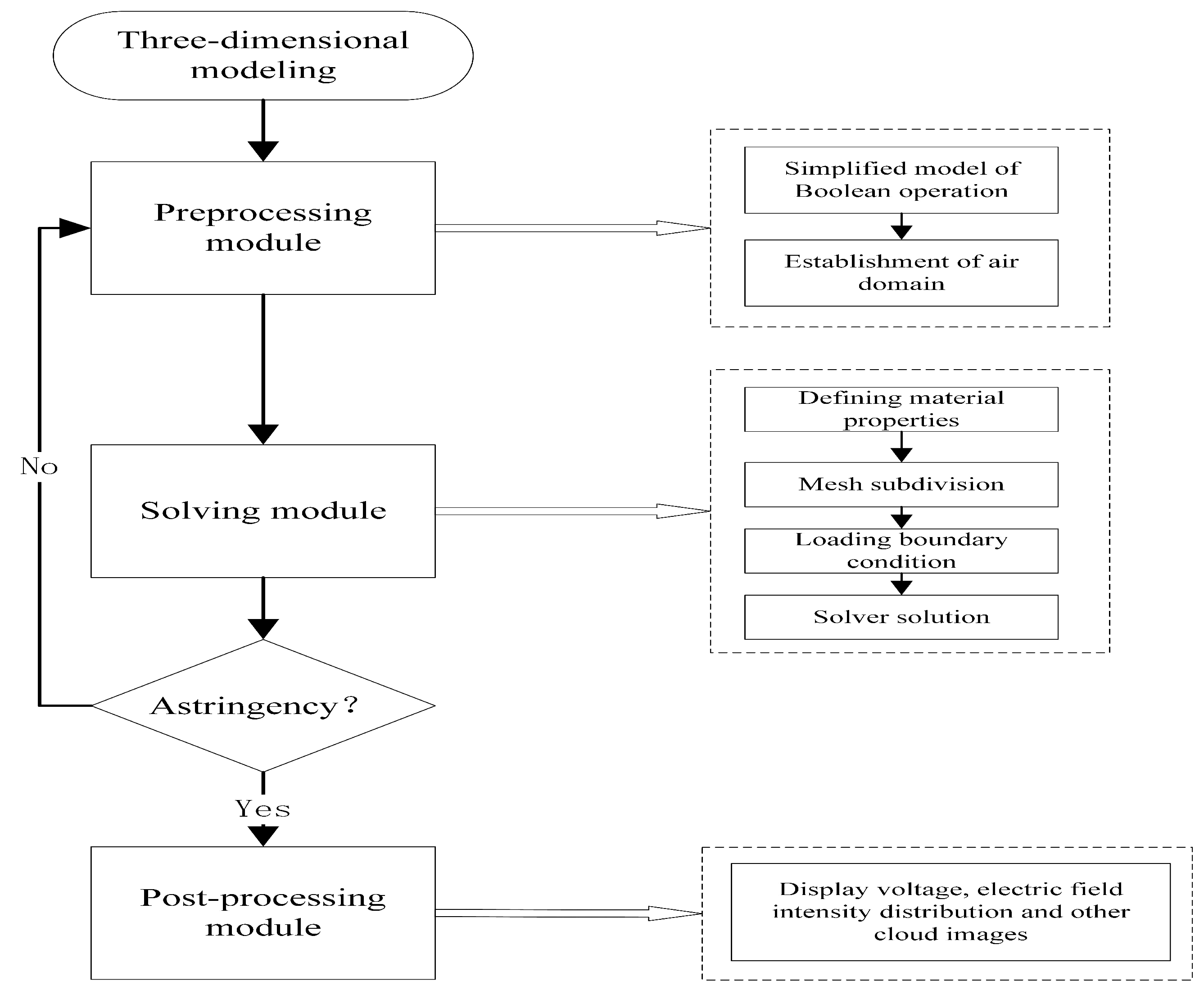
2.1. Static-Field Simulation Analysis Process

ANSYS Workbench is a multi-physics analysis platform created by the ANSYS Corporation, which can interact with commonly used 3D drawing design software, such as CAD and Solidworks, and has convenient pre- and post-processing operations and powerful solving functions. The pre-processing module Gemetry has model-processing functions such as the Boolean operation, which conveniently allows users to construct a finite element model and establish a suitable air domain. The solution module Mechanical enables material property definitions, mesh generation, load boundary conditions, and specific finite element analysis and calculations to be carried out on the 3D model processed by the pre-processing module. This module has a sensitive and accurate analysis ability. If there is no convergence in the calculation and analysis process, the solver will report an error message and immediately stop solving. At this time, it is necessary to return to the pre-processing module for model reprocessing and to re-partition the appropriate grid before calculation until the calculation converges and the correct result is obtained. The post-processing module can display the calculation result of the solver in many ways, such as through a color contour display, gradient display, vector display, three-dimensional slice display, transparent and translucent display, etc.
Therefore, the Electric module from the ANSYS Workbench platform was used in this paper to conduct electrostatic-field simulation analysis of the fuse tube, and the simulation analysis process is shown in Figure 1.

2.2. Theoretical Basis of Electric-Field

ANSYS uses Maxwell’s equations as the starting point for electromagnetic field analysis. Maxwell’s equation contains four laws: Ampere’s loop law, Faraday’s electromagnetic induction law, Gauss’s law, and Gauss’s law for magnetism. Gauss’s law is an important law in the study of electrostatic-fields, which can help us to calculate the intensity and distribution of an electric-field. In practical applications, Gauss’s law clearly describes the relationship between the electric-field and the charge distribution in space, stating that the electric-field line starts at a positive charge and ends at a negative charge or infinity.
Equation (1) is the expression of Gauss’s law in electrostatics. This formula indicates that the electric flux through a closed surface is proportional to the amount of charge surrounded by the closed surface, that is the surface integral of the electric-field strength on a closed surface is proportional to the amount of charge surrounded by the closed surface.
S E · d S = Q ε 0
In the formula, S represents any closed surface, E represents the electric-field strength, d S represents the area of the element on the surface, Q represents all the charge in the area enclosed by the closed surface S, and ε 0 represents the dielectric constant in the vacuum.
When the electromagnetic field to be analyzed or solved is close to the steady state and because the electric flux density value solved via Maxwell’s equations is very small compared with the value of the conduction current density, the magnetic field generated by the changing electrical field can be ignored.
The static equilibrium state of a conductor is a state in which there is no directional charge movement inside or on the surface of the conductor. A conductor in electrostatic equilibrium has a zero net charge everywhere inside of it, and the charge is distributed only on the conductor surface.

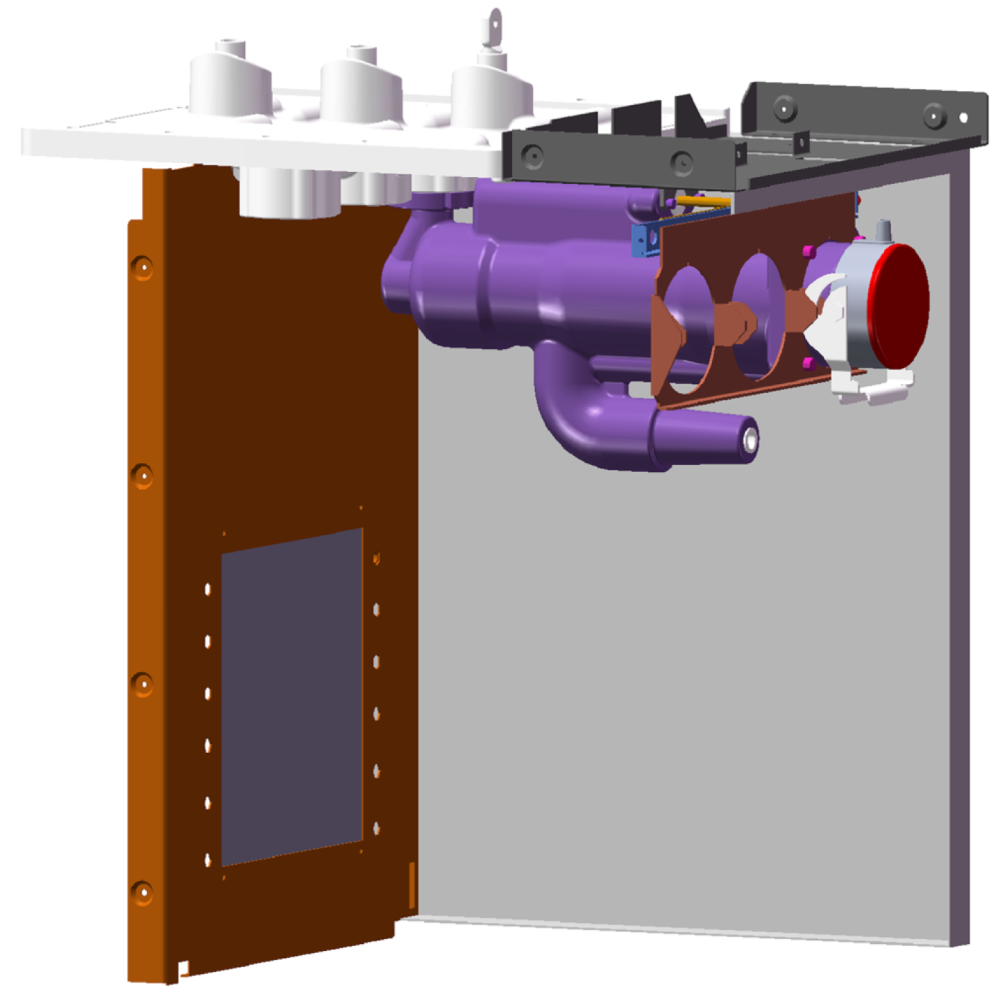
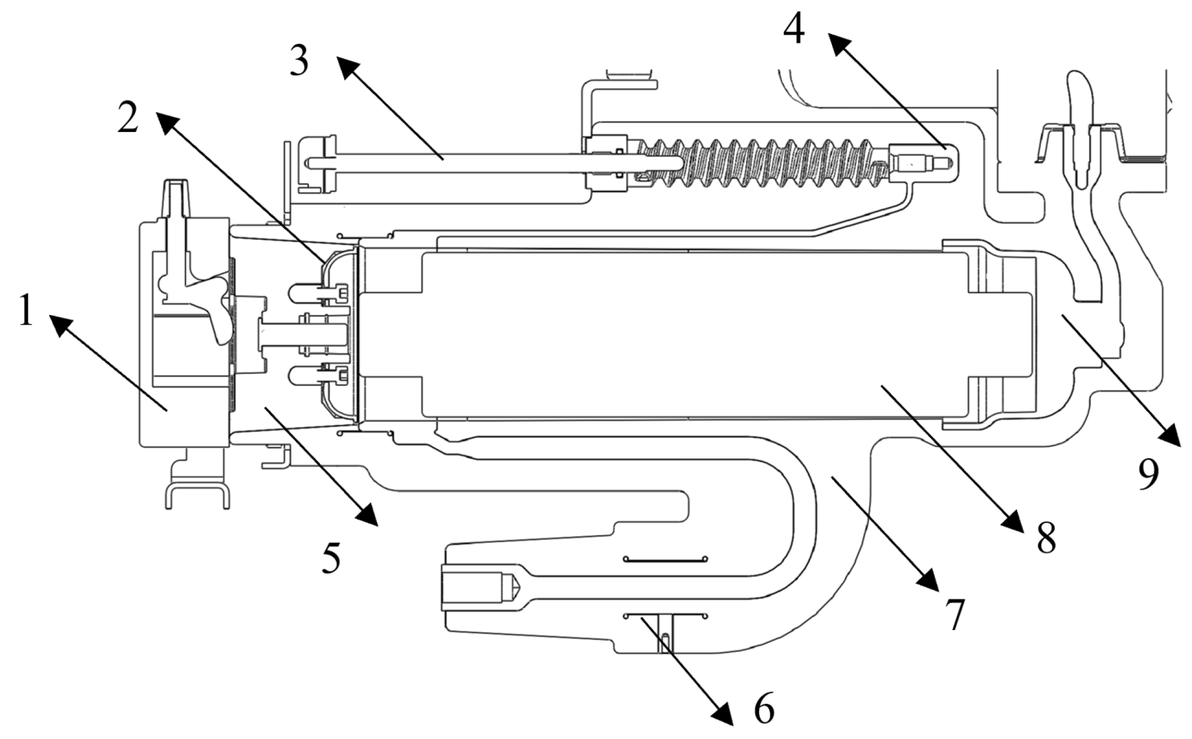
2.3. The Establishment of Simulation Model

The fuse tube is an insulating part made of fuses, other conductors, and insulating rubber sleeves wrapped in an epoxy-resin-cast body. This component cannot only effectively reduce the influence of the external environment on fuses and other conductors, but also improve the overall insulation strength of the equipment.
Due to the symmetry of the three phases of the switchgear and the symmetry of the electric-field distribution in the fuse tube, in order to reduce the time of the model calculation, only one phase of the fuse tube was analyzed. On the premise that the electric-field distribution is not affected, the original model was simplified, the irrelevant components were removed as much as possible, and the relevant features that did not affect the electric-field distribution were simplified. The simplified model is shown in Figure 2. The profile view of the 12 kV fuse tube is shown in Figure 3. Its main components included a fuse, metal guide rod, ground rod, plug and epoxy resin shell, etc.
The fuse tube model simplified in SolidWorks was imported into the ANSYS Electric module for the simulation calculation. The interference between the interior of the model was removed; the calculation domain of the model was set; the conductors of high potential and zero potential were determined. Then, the calculation domain was divided into grids, and the boundary conditions were loaded to carry out the calculation.
The actual distribution of the electric-field was located in the medium and was filled with infinite space, and the finite element analysis method electric-field simulation actually used a finite domain, which simulated the entire space of the medium to calculate the electric-field, where the boundary of the domain size was the field boundary. The medium propagating around the electric-field of the fuse tube was air, so this limited field was called the air domain.
The electrical performance parameters involved in the simulation analysis of the electrostatic-field were mainly the relative dielectric constant and the breakdown of the field strength of insulating materials. The fuse tube model contained three kinds of insulating materials, namely air, silicone rubber, and epoxy resin. The electrical performance parameters are shown in Table 1.
After the simulation model was established, the whole computing domain needed to be divided into millions of small polyhedra for the calculation. Whether the grid division is good or bad will affect the convergence of the entire electrostatic-field simulation calculation. Therefore, the model grid needed to be divided into appropriate shapes and sizes. To define the type of material and grid division, commands must be added to Mechanical, which were mainly solid121 and solid123, which were meant to divide the three-dimensional model grid into different shapes, namely hexahedrons and tetrahedrons. In engineering, solid123 is usually used to divide the grid; “et, matid, 123” is used to change the unit type and makes the numbered material number the same; “mp, perx, matid, 1et” is used to define the model material parameters, the electrostatic-field analysis environment, and the digitally altered dielectric constant.
For the setting of the epoxy material in the fuse tube, use the “et, matid, 123; mp, perx, matid, 4.5” command. For the setting of the silicone rubber material, use the “et, matid, 123; mp, perx, matid, 3.6” command. For air settings, use the “et, matid, 123; mp, perx, matid, 1” command.
In the simulation process, according to the actual operation of the fuse tube, the internal fuse conductor and ring conducting rod were set as having high potential; the ground rod, internal shielding ring, and external metal side plate were set as having zero potential; the screws in the plug were set as having suspension potential. In order to better predict the location in the fuse tube that was prone to insulation breakdown, the high-potential processing power frequency withstand voltage peak was 42 kV × 2 = 59.39 kV, with a zero potential ground.
Therefore, set the boundary condition to:
φ L 1 = 59.39 kV
φ L 2 = 0 kV
φ n L 3 = 0
where φ is the potential; L 1 and L 2 are the high and ground potential boundaries, respectively; L 3 is the boundary at infinity. By solving the above formula, the potential of the three points can be obtained, and then, the field strength of each node can be calculated from the formula E = g r a d φ .

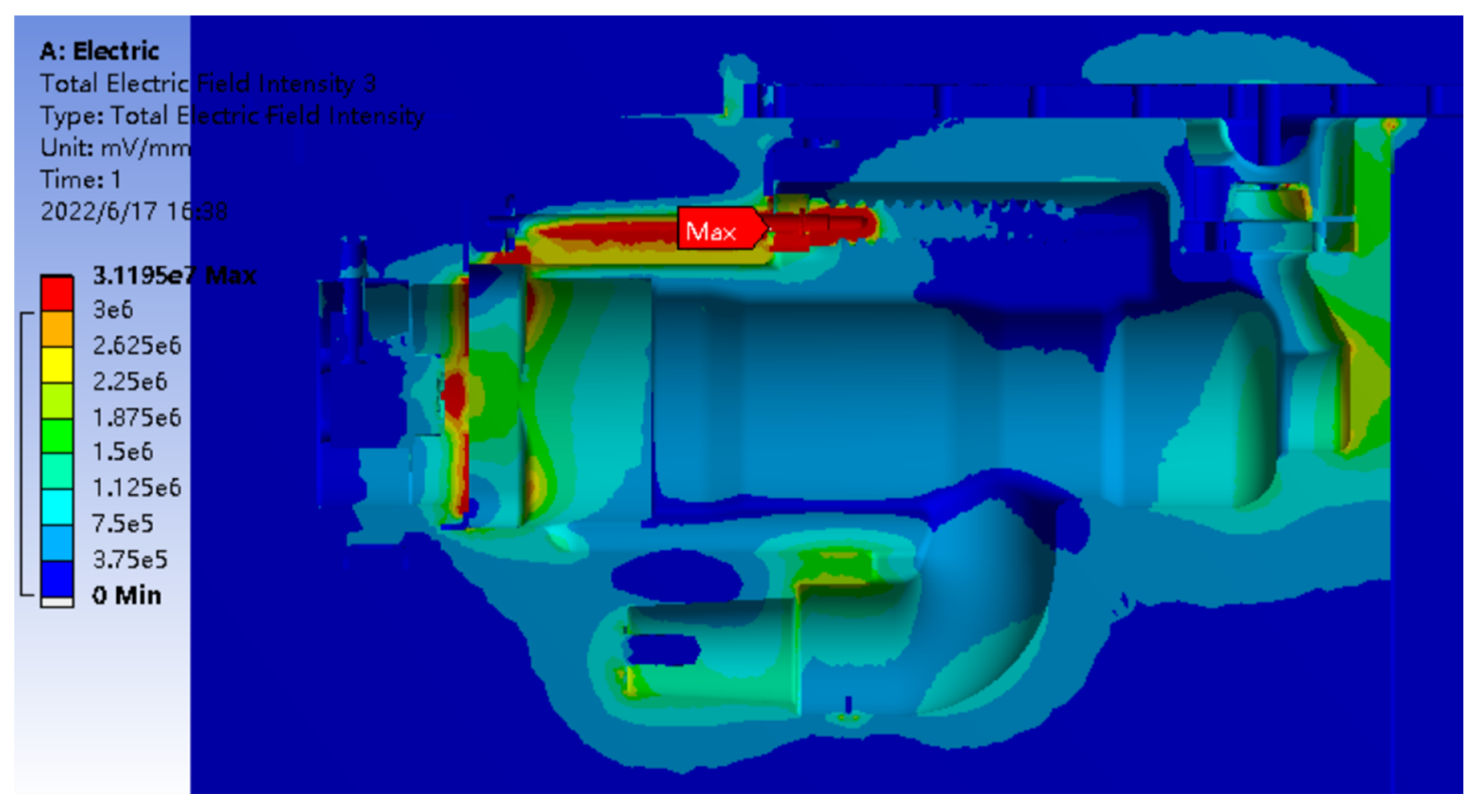
2.4. Electric-Field Simulation and Result Analysis
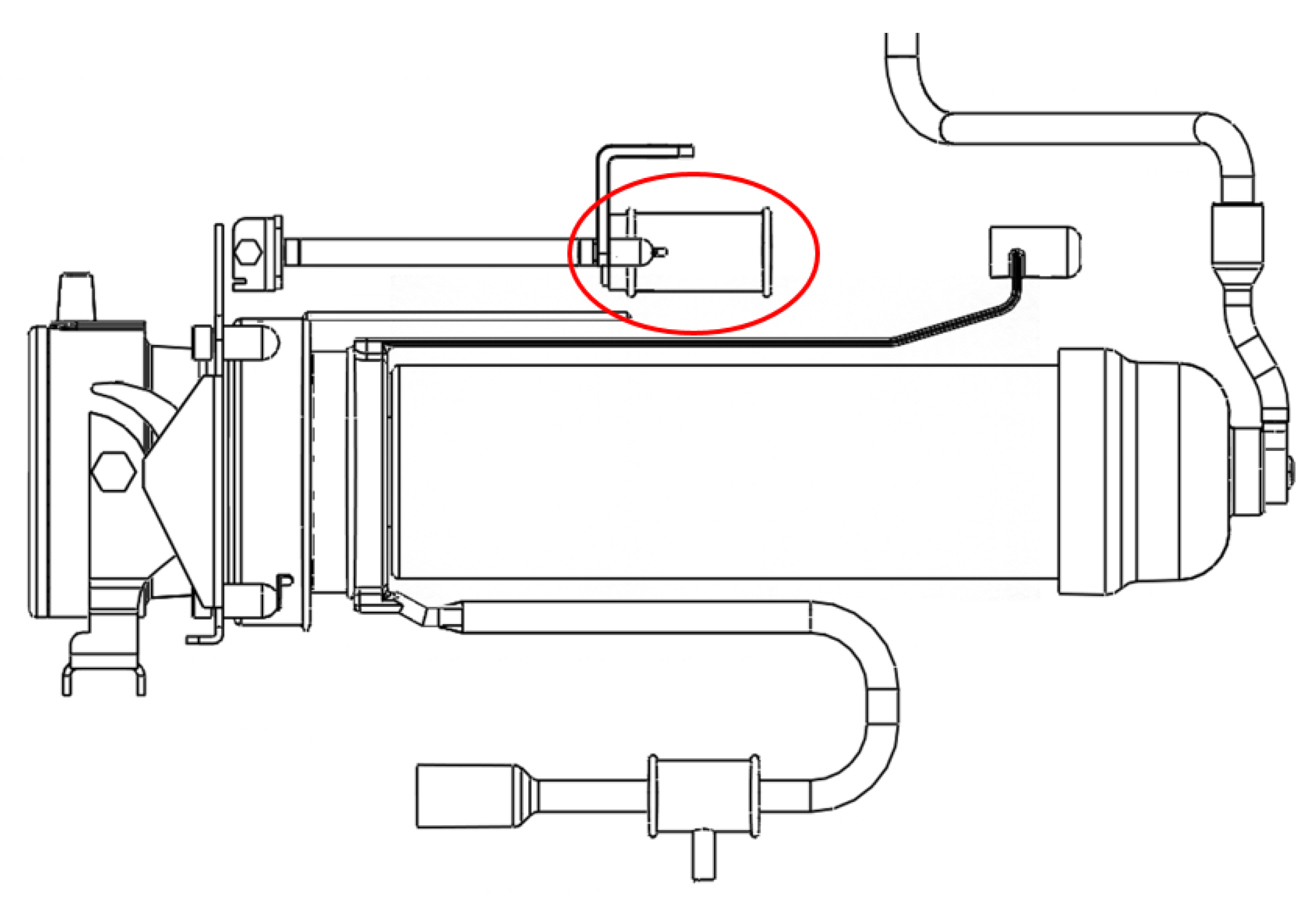
After the pre-processing of the electric-field simulation was completed, the solver was opened for completing the calculation. ANSYS has a powerful post-processing tool. The following part will expand the solution post-processing and analyze the solution results of the fuse tube from the aspects of a voltage cloud diagram, electric-field cloud diagram, and electric-field vector diagram. Before the improvement of the fuse tube, a voltage distribution nephograph of the calculation domain is shown in Figure 4, an electric-field distribution nephograph of the epoxy resin shell is shown in Figure 5, and an electric-field distribution nephograph of the air domain is shown in Figure 6.
As can be seen from the distribution of the electric-field strength of the epoxy shell in Figure 5, the maximum field strength of the epoxy shell of the fuse tube appeared at the ground shielding ring inside the fuse tube, which was 13.11 kV/mm. It was less than the breakdown field strength of the epoxy resin at 30.0 kV/mm, which will not cause insulation breakdown and affect the insulation performance of the fuse tube.
The average breakdown field strength of air is only 3 kV/mm, which can easily cause the breakdown of air during the operation of the switchgear. Therefore, the breakdown of the air gap has always been the key and a difficult problem in the insulation design of switchgears. In order to facilitate the observation of the field intensity distribution in the air domain, the location with insulation performance problems was accurately located, and the part of the cloud image with an air field intensity exceeding 3 kV/mm was set as red. As can be seen from the cloud diagram of the electrostatic-field distribution in the air domain in Figure 6, the maximum field strength in the air domain of the fuse tube at the ground rod was 31.2 kV/mm, which is far greater than the breakdown field strength of the air. The insulation performance of the fuse tube structure under the condition that air is the insulating medium was far from meeting the standard requirements. Through the analysis of simulation results, it was found that the current structure mainly had the following problems:
(1)
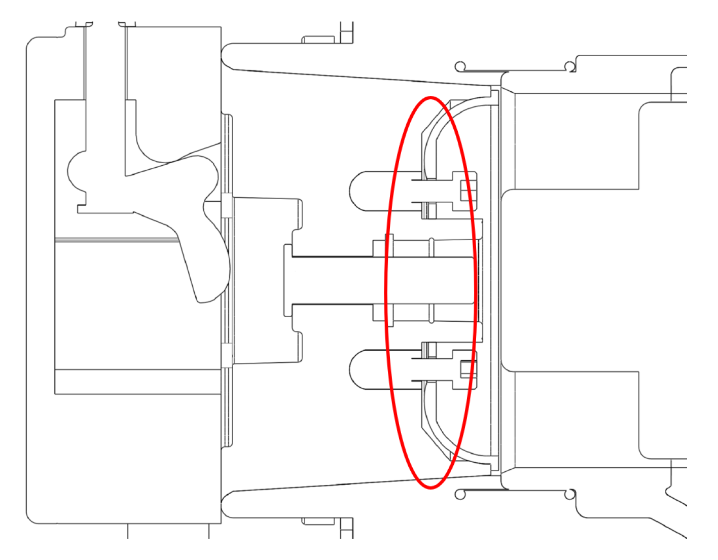
Because the installation led to many air gaps in the plug, these air gaps and the surrounding conductors and silicone rubber formed a high potential, insulation and air three different media intersection, resulting in the concentration of the field in the plug, easily causing insulation breakdown.
(2)
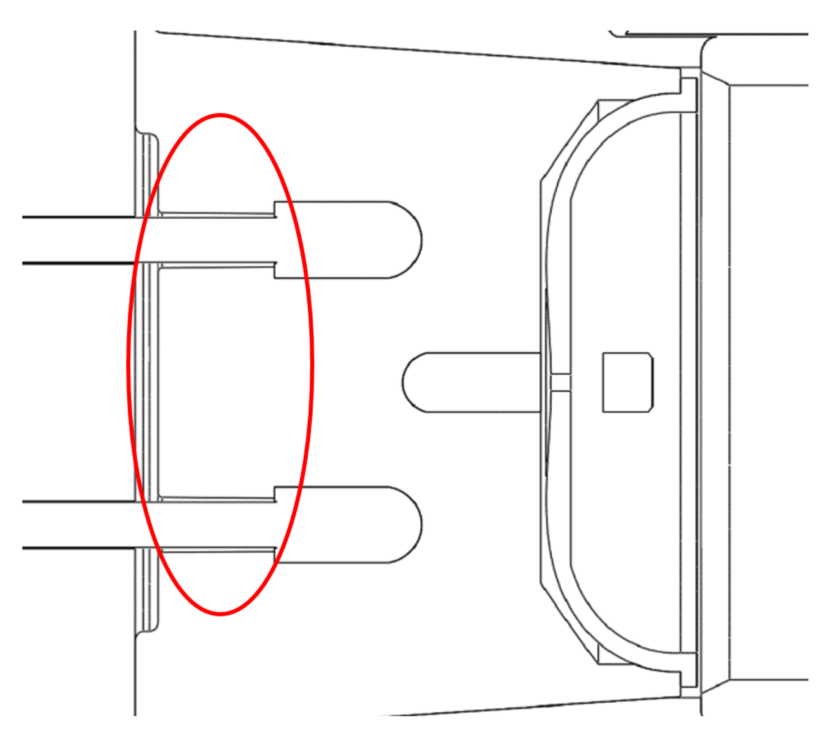
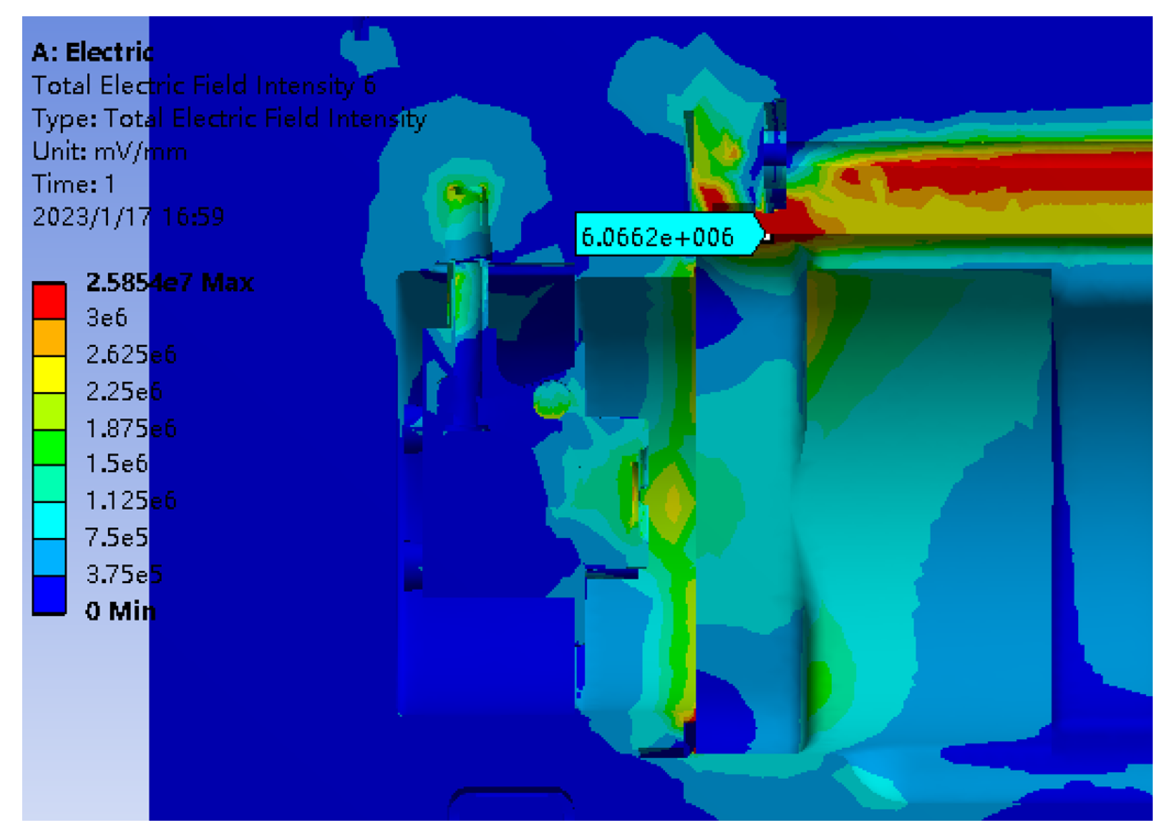
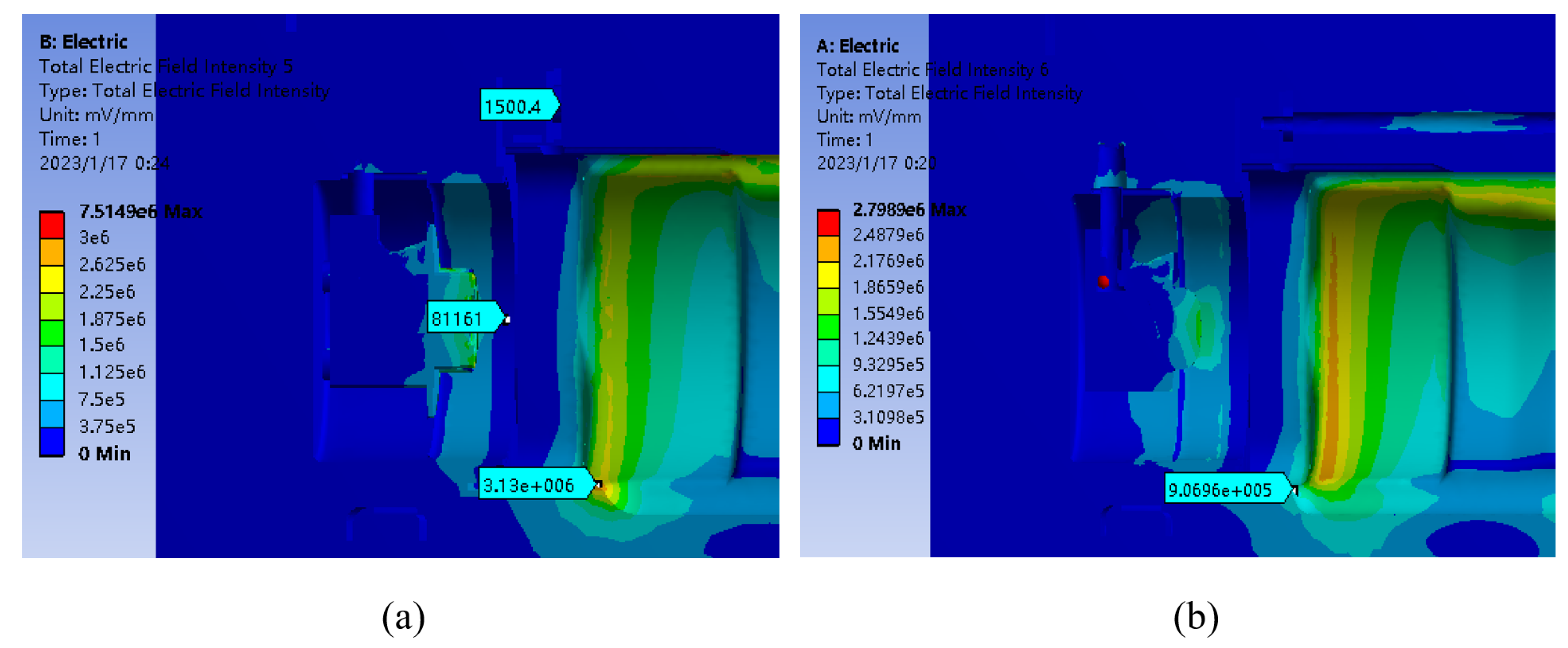
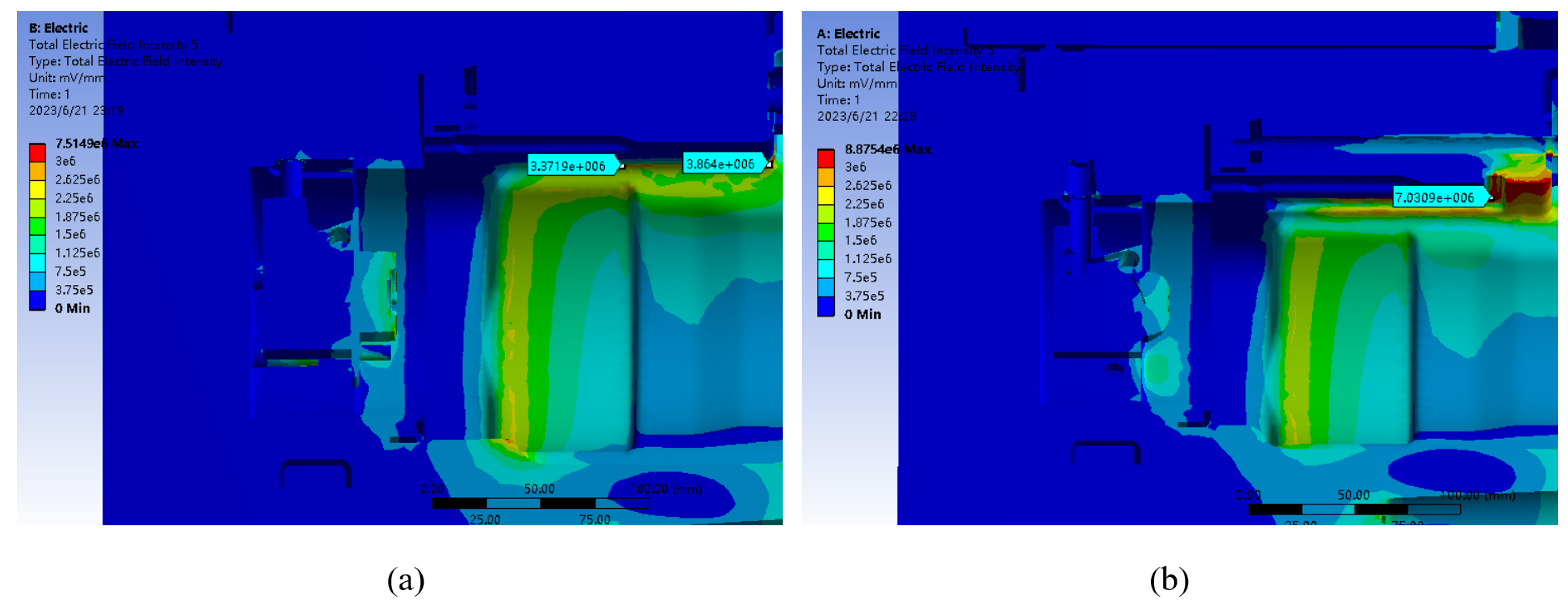
The ring rod and other metals inside the fuse tube had high potential, and the ground rod had low potential. The potential passed through the air from a high potential to a low potential, and so, the air field around the ground rod and connecting rod was very strong.

3. Design of Improvement Scheme of Fuse Tube

Based on the analysis of the above electric-field simulation results, the improvement of the fuse tube structure was mainly divided into two parts: one part was the plug of the fuse tube, and the other part was the ground rod of the fuse tube.

3.1. Plug Part Improvement

3.1.1. Improvement of Air Gap between Plug and Alloy Cover

As shown in Figure 7, circled in red, due to the air gap between the high-potential alloy cover and the silica gel, when there was a potential air insulation multi-dielectric intersection, the electric-field easily became more concentrated and breakdown occurs. The maximum field strength of 12.82 kV/mm is far greater than that of air breakdown, as shown in Figure 8a.
In practice, the air at this point cannot be completely filled by silica gel, so the silicone surface adjacent to the alloy cover can only be brushed with semiconductor paint to form equipotentiality and to even out the air field intensity at this point, as shown in Figure 9. The improved results are shown in Figure 8b. Equipotentiality was formed around the air, and the electric-field intensity was effectively reduced to about 0 kV/mm, which will not cause insulation breakdown.

3.1.2. The Screw Inside the Plug Is Improved

Since the suspension potential is not equal to no potential and the plug was close to having high potential, the screw had a suspension potential, as well as a high potential, as shown in Figure 10.
The voltage of the screw was about 17.8 kV, which was about equal to having high potential. In addition, there were many air gaps between the plug and screw, as shown in Figure 11, circled in red. As a result, the field strength was concentrated in the air slit between the insulation and high potential, as shown in Figure 12a. The maximum field strength was 3.36 kV/mm, which is greater than the air breakdown field strength.
Although the dielectric strength of silicone rubber is much greater than that of air, the existence of an air gap should be reduced as much as possible, and insulating materials with a high dielectric strength should be used in places with an uneven electric-field distribution and large field strength. However, in actual engineering, because screws need to be installed or removed, an air gap is bound to exist, and silicone rubber cannot be used for pouring and filling. Therefore, the silicone rubber surface was brushed with conductive paint around the screw air gap to form the suspension potential, which was equipotential with the screw. The improved results are shown in Figure 12b, where the field strength was greatly reduced to about 0 kV/mm.

3.2. Ground Rod Partial Improvement

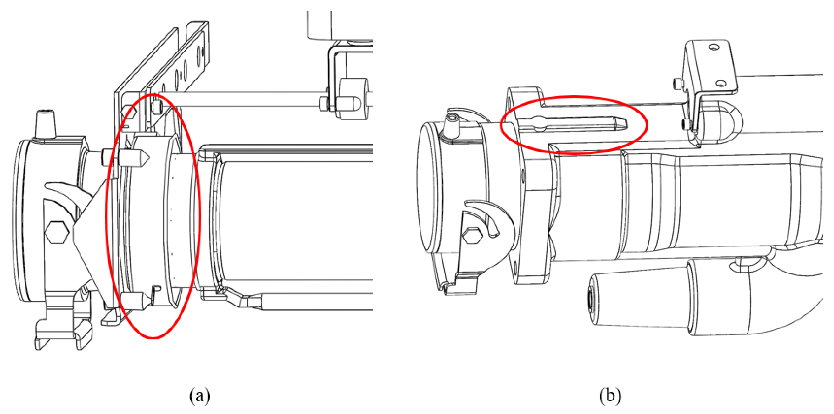
3.2.1. Improvement of Grounding Connecting Rod

Because the distance between the connecting rod at the front-end of the ground rod and the high-potential conductor inside the fuse tube was relatively close and because the ground rod was exposed to the air of the switch cabinet, air breakdown easily occurred, as shown in Figure 13.
Because the breakdown field strength of epoxy resin is 30 kV/mm, which is much higher than the breakdown field strength of air, epoxy resin is not easily broken down. Thus, the ground shielding net was added to the epoxy shell directly below the grounding connecting rod so that the potential was shielded inside the fuse tube. When the ground shielding net was increased, if the thickness of the nearby solid insulation was not increased, the distance between the shielding net and the grounding rod will be reduced, and the field strength will also increase. Therefore, when the ground shielding net increases, the epoxy thickness should be increased to prevent breakdown. Considering the distance between the ground rod and the epoxy shell, the increased epoxy thickness cannot affect the movement of the ground rod, so a 4 mm small boss was added on the surface of the square fuse tube on the shielding net, as shown in Figure 14, circled in red.
As shown in Figure 15a, it can be seen that a ground shielding ring was added inside the epoxy shell of the fuse tube to shield the potential in the epoxy shell with a high dielectric strength and effectively reduce the field strength. However, due to the addition of a ground shielding net in the epoxy shell, the wall of the tube under the fuse tube became thinner, resulting in the maximum field strength of the air outside the tube wall corresponding to the shielding net being 3.13 kV/mm, which may lead to the deterioration and breakdown of the epoxy resin sleeve insulation. Therefore, the structure was further improved, and the epoxy shell under the fuse tube was extended to the front boss of the fuse tube. The thickness of the epoxy shell increased, as shown in Figure 16.
As can be seen from the simulation results in Figure 15b, after increasing the thickness of the epoxy shell, the improvement effect was obvious. The air field strength in this area was no longer concentrated, and the field strength in this area dropped to 0.9 kV/mm, which was lower than the air breakdown field strength.

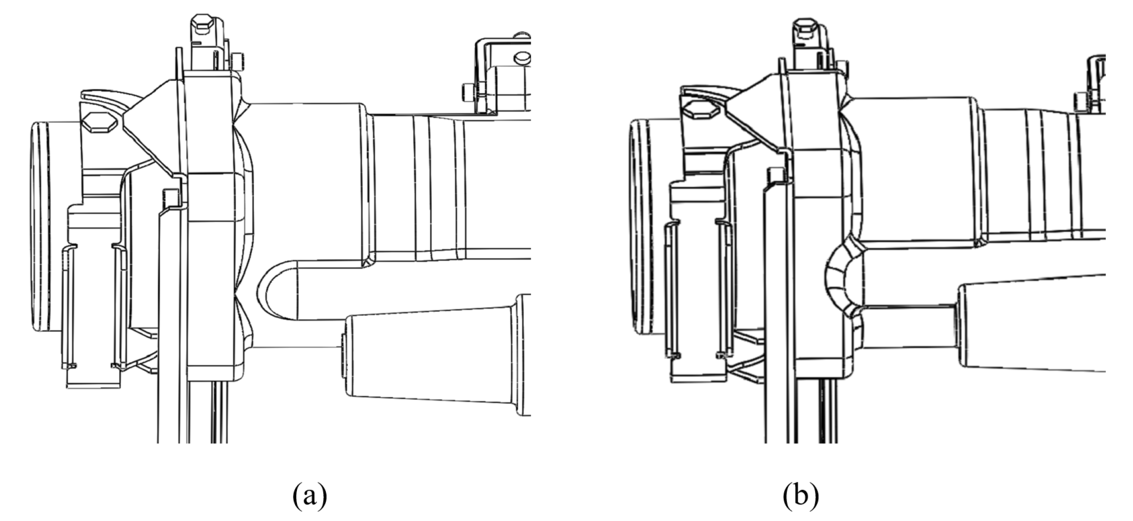
3.2.2. Ground Rod Front-End Air Zone Improvement

As shown in Figure 17a, for the improvement of the air domain at the front-end of the ground rod, the upper surface of the fuse tube was grounded by spraying it with zinc so that the potential was shielded from the surface of the epoxy shell without passing through the air part. However, as can be seen from the improvement results in Figure 18a, although zn-spraying grounding shielded most of the electric-field, the field strength was greatly reduced. However, because the potential at the edge of the area sprayed with zinc was connected to the air and insulation, the electric-field at the edge was concentrated, and the field intensity in the air domain was still greater than that of the air breakdown field. Based on the improvement results, a 4 mm U-shaped boss was added and zinc was sprayed onto the boss indirectly, as shown in Figure 17b. However, it can be seen from the simulation results that the air field strength at the edge and groove of the zinc spraying was still greater than the air breakdown field strength, as shown in Figure 18b.
Based on the results of the two zinc-spraying schemes, it can be seen that the grounding method of zinc spraying can shield most of the potential, but under the action of alternating voltage, the edge of zinc spraying will appear along the surface discharge and then develop into surface flashover, resulting in the breakdown of air. Therefore, the improvement method of zinc spraying is not feasible for the fuse tube structure. Therefore, referring to the improved design of the connecting rod of the upper section, a 40 mm × 133.5 mm ground shielding net was added inside the fuse tube, which was 8 mm away from the surface of the high-potential ring rod so that the high-potential ring rod and fuse directly discharged through the epoxy resin ground shielding net. Thus, the potential was completely shielded inside the fuse tube without passing through the air between the grounding rod and the epoxy shell, as shown in Figure 19, circled in red.
As shown in Figure 20, by adding a metal shielding net, the air field strength around the grounding rod was greatly reduced, and the air breakdown field strength did not exceed the standard requirements.

3.2.3. Ground Rod Rear-End Air Zone Improvement

As shown in Figure 21, the metal ring rod had a high potential, while the ground rod had a low potential. The high and low potentials were close to each other in this area. As shown in Figure 22, a ground shielding ring with a radius of 15.5 mm and a length of 56.5 mm was inserted into the epoxy shell at the end of the ground rod. As can be seen from the simulation results in Figure 23, circled in red, the strength amplitude of the improved electric-field was reduced to 3.67 kV/mm, with a decrease of about 74%. Thus, it can be seen that the scheme of adding a ground shielding ring was feasible. Although the electric-field strength here was effectively improved, it was still slightly greater than the air breakdown field strength; so, it was necessary to find the optimal improvement plan through a series of data comparative analyses.
In the electric-field vector diagram in the air domain at the end of the ground rod in Figure 24, the direction of the arrow represents the direction of the potential, that is the high potential points to the low potential ground shielding ring. The arrow in the figure mainly points to the low potential ground shielding ring from the end of the high potential ring, indicating that the electric-field mainly reached the ground rod through the air in the epoxy shell rather than directly through the solid insulation epoxy to reach the low potential. Therefore, it can be known that the length of the shielding ring will have an impact on the air field intensity at the end of the ground rod. If the electric-field intensity here were reduced, it would be very important to select an appropriate length for the shielding ring.
According to the above analysis, the shielding rings of different lengths were compared and simulated. When the length of the shielding ring was 40.5 mm, the end of the grounding rod would exceed the end of the shielding ring. Considering that the shielding ring needs to completely cover the grounding rod to ensure its shielding effect, a simulation test with a 42.5 mm shielding ring was conducted. The simulation results are shown in Figure 25.
As shown in Figure 25, the simulation results showed that, when the radius of the shielding ring was 15.5 mm, the field strength in the air domain was the lowest when the length of the shielding ring was 42.5 mm, being 3.05 kV/mm, but it was still slightly greater than the air breakdown field strength. Therefore, under the condition of ensuring that the wall of the insulation tube is not too thin to cause breakdown, the radius of the shielding ring with a length of 42.5 mm was expanded from 15.5 mm to 17 mm so as to increase the distance between potentials. As shown in Figure 26, when the radius of the shielding ring was 17 mm and the length was 42.5 mm, the maximum field strength of the air domain at the end of the ground rod was reduced to 2.83 kV/mm, which did not exceed the air breakdown field strength, achieving the purpose of reducing the field strength.
After comparing the improvement results several times, as shown in Table 2, the electric-field simulation results from the ground shielding rings of different sizes showed that, when the radius of the shielding ring was 17 mm and the length was 42.5 mm, the maximum field strength in the air region at the end of the ground rod was the lowest, and the shielding effect of the ground shielding ring was the best.

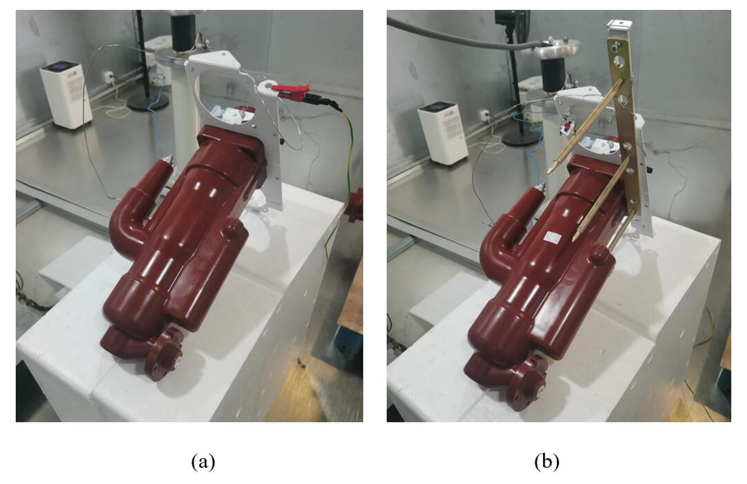
4. Partial Discharge Test of Fuse Tube

In order to verify the accuracy of the analysis of the electric-field distribution of the switchgear using the finite element software ANSYS and the feasibility of the improvement scheme in engineering practice, several sets of partial discharge tests were carried out on the fuse tube before and after improvement, as shown in the Figure 27 and Figure 28. In order to ensure the accuracy of the partial discharge test, the process was as follows: first, to ensure that the fuse tube processing power frequency could withstand a voltage of 42 kV, wait for the voltage stability, then reduce the voltage to 0 kV, and then, slowly increase the voltage until the discharge arc, the local discharge and the initial discharge voltage were measured. According to the requirements of the industry standards, the partial discharge of the fuse tube must be less than 10 pC when the partial discharge voltage is 1.2-times the rated voltage. The rated voltage of the fuse tube is 12 kV, the partial discharge voltage of the fuse tube should be less than 10 pC to meet the insulation requirements under the condition that the partial discharge voltage is greater than or equal to 14.4 kV.
The sample numbers of the fuse tube without a grounding rod were set as A01-03 after the plug was improved. The sample numbers of the fuse tube with a grounding rod only after plug improvement were B01-03. After the plug and grounding rod were improved, the fuse tube sample numbers were C01-03.
According to the results of the partial discharge test in Table 3, it can be found that, under the condition that the partial discharge voltage of Group A was greater than or equal to 14.4 kV, the local discharge quantity was less than 10 pC. Therefore, after the completion of the plug improvement, the fuse tube met the insulation requirements without a grounding rod, which verified the effectiveness of the plug improvement. Compared with the results of the A01-03 samples under the same test environment, the initial discharge voltage of the B01-03 samples was lower, and the discharge energy of the Group B samples was exponentially increased; the discharge energy of the Group B samples was much higher than the industry standard of 10 pC. From this, it can be concluded that a partial discharge fault easily occurred with the grounding rod. In the electrostatic-field simulation of the original model above, the field strength around the grounding rod was indeed very uneven and too large, which validated the correctness of the electrostatic-field simulation analysis. As shown in the test data of Group C, the further improvement of the butt rod part on the basis of the improvement of the plug successfully achieved a significant reduction in the discharge capacity of the fuse tube to within the 10 pC standard, which proved the rationality of the above series of improvements and the feasibility of using electrostatic-field simulation analysis to solve the insulation problem of the switchgear.

5. Conclusions

Based on the above research, the improvement and optimization of a fuse tube are summarized as follows:
(1)
Brush conductive paint on the silicone rubber surface adjacent to the alloy cover to form equipotentiality, so as to avoid the formation of a high potential, insulation, and air intersection, which results in a gas gap discharge.
(2)
Brush conductive paint on the silicone rubber wall around the slit of the screw in the plug, which forms the suspension potential, equipotentiality, and the uniform electric-field with the screw.
(3)
Add a ground shielding net to the fuse tube directly below the grounding connecting rod. The metal shielding structure adopts epoxy resin through integrated pouring so that the potential shield is inside the fuse tube. Then, add a small 4 mm high boss on the surface of the fuse tube above the shielding ring; the lower end of the epoxy shell grows to cover the fuse tube front boss, increasing the epoxy thickness to prevent breakdown.
(4)
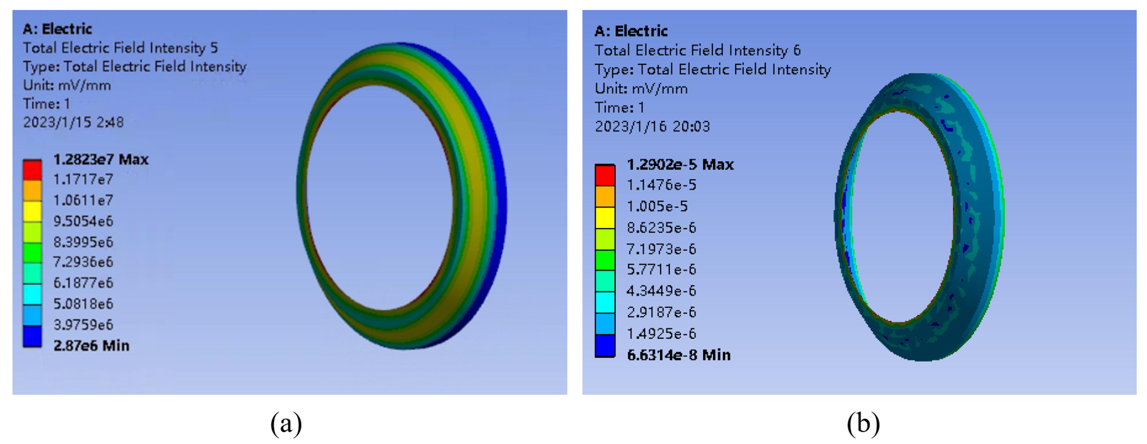
Add a 40 mm × 133.5 mm earth shielding net inside the fuse tube that is 8 mm away from the surface of the high-potential ring rod, and shield the electric-field inside the epoxy.
(5)
Add a 42.5 mm-long and 17 mm-radius ground shielding ring at the end of the grounding rod to avoid electric-field concentration and insulation breakdown.
In this study, through electric-field simulation, the structure of the place where the electric-field strength is too high and the main reasons leading to the high field strength were analyzed, and the corresponding improvement scheme was proposed. Through the above series of structural improvement, the electric-field intensity can be effectively reduced. As shown in Figure 29, compared with the simulation results of the fuse tube before improvement, the maximum electric-field strength in the air domain was reduced from 31.2 kV/mm to 2.8 kV/mm, which is lower than the air breakdown field strength of 3 kV/mm, meeting the insulation requirements. At the same time, the improved fuse tube passed the partial discharge test, which verified the rationality and feasibility of the above series of improved designs for utilization in actual engineering. The improvement scheme greatly improved the insulation performance of the fuse tube, leading it to obtain the same insulation level as the S F 6 -insulated switchgear without increasing the inflation pressure and cabinet size.

Author Contributions

Conceptualization, Y.Y.; methodology, Y.Y. and R.Q.; software, R.Q.; validation, R.Q. and S.L.; formal analysis, S.Z. (Shunxiong Zhou); data curation, S.Z. (Shenjun Zhou) and Z.P.; writing–original draft preparation, R.Q.; writing–review and editing, S.L.; funding acquisition, Y.Y. All authors have read and agreed to the published version of the manuscript.

Funding

This work was supported in part by the Xiamen Key Laboratory of Frontier Electric Power Equipment and Intelligent Control, Xiamen 361024, China.

Data Availability Statement

Data available on request due to restrictions eg privacy or ethical The data presented in this study are available on request from the corresponding author. The data are not publicly available due to manufacturer’s trade secret.

Conflicts of Interest

The authors declare no conflict of interest.

References

  1. Wegierek, P.; Kostyla, D.; Lech, M. Directions of Development of Diagnostic Methods of Vacuum Medium-Voltage Switchgear. Energies 2023, 16, 2087. [Google Scholar] [CrossRef]
  2. Zhang, T.; Zhou, W.; Yu, J.; Yu, Z. Insulation properties of C4F7N/CO2 mixtures under lightning impulse. IEEE Trans. Dielectr. Electr. Insul. 2020, 27, 181–188. [Google Scholar] [CrossRef]
  3. Li, Y.; Wang, Y.; Xiao, S.; Li, Z.; Tang, N.; Zhou, Y.; Li, L.; Zhang, Y.; Tang, J.; Zhang, X. Partial discharge induced decomposition and by-products generation properties of HFO-1234ze(E)/CO2: A new eco-friendly gas insulating medium. J. Phys. D Appl. Phys. 2023, 56, 165203. [Google Scholar] [CrossRef]
  4. Sun, T.; Li, L.; Li, G.; Yang, S.; Wang, W. Evaluation and optimization of electric-field on a high-voltage switchgear in nuclear power station. Electr. Eng. 2021, 103, 2733–2746. [Google Scholar] [CrossRef]
  5. Ghasemzadeh, M.R.; Faghihi, F.; Mozafari, S. FEM analysis of elliptical void in insulator of GIS compartment based on electric-field distribution. Electr. Power Syst. Res. 2023, 220, 109261. [Google Scholar] [CrossRef]
  6. Li, X.; Zhang, G.; Cao, C.; Shi, Y.; Li, J.; Chang, W. Effects of volume and surface conductivity on the surface charge and electric-field characteristics of the tri-post insulator in SF6-filled +/− 500 kV DC-GIL. IET Gener. Transm. Distrib. 2023, 17, 230–239. [Google Scholar] [CrossRef]
  7. Zheng, Y.; Xiao, S.; You, Y.; Ma, Z.; Huang, S. Partial discharge of fuse tube based on electrostatic-field simulation. High Volt. Eng. 2018, 54, 157–164. [Google Scholar] [CrossRef]
  8. Vu-Cong, T.; Toigo, C.; Jacquier, F.; Girodet, A.; Tuczek, M.N.; Riechert, U.; Mor, A.R. Long-Term Partial Discharge Behavior of Protrusion Defect in HVDC GIS. IEEE Trans. Dielectr. Electr. Insul. 2023, 29, 2294–2302. [Google Scholar] [CrossRef]
  9. Li, S.; Song, P.; Wei, Z.; Li, X.; Tang, Q.; Meng, Z.; Li, J.; Liu, S.; Wang, Y.; Li, J. Partial Discharge Detection and Defect Location Method in GIS Cable Terminal. Energies 2023, 16, 413. [Google Scholar] [CrossRef]
  10. Yao, Y.; Ouyang, X.; Zeng, G.; Tang, Q.; Ma, W. Research on modularizing design of 10 kV switchgear with line outlet for live maintenance. Energy Rep. 2021, 7, 10–16. [Google Scholar] [CrossRef]
  11. Krajewski, W.; Krasuski, K.; Blazejczyk, T. Some aspects of medium voltage switchgear designing with aid of numerical analysis. IET Sci. Meas. Technol. 2020, 14, 651–664. [Google Scholar] [CrossRef]
  12. Geng, J.; Qin, Y.; Lv, F.; Yao, X.; Ding, Y. Electric Field Distribution and Switching Impulse Discharge under Shield Ball Surface Scratch Defect in an UHVDC Hall. Energies 2018, 11, 1408. [Google Scholar] [CrossRef] [Green Version]
  13. Carlos del-Pino-Lopez, J.; Hatlo, M.; Cruz-Romero, P.; Filho, S. On Simplified 3D Finite Element Simulations of Three-Core Armored Power Cables. Energies 2018, 11, 3081. [Google Scholar] [CrossRef] [Green Version]
Figure 1. Simulation flow chart of electrostatic-field of the fuse tube.
Energies 16 05242 g001
Figure 2. Overall model of the simplified switchgear.
Energies 16 05242 g002
Figure 3. Cross-section of the simplified fuse tube: 1—end cover; 2—alloy cover; 3—ground rod; 4—conducting ring rod; 5—plug; 6—metal shielding ring; 7—epoxy resin shell; 8—fuse conductor; 9—metal rear cover.
Energies 16 05242 g003
Figure 4. Nephogram of voltage distribution in the computing domain.
Energies 16 05242 g004
Figure 5. Electric-field distribution nephogram of epoxy resin shell.
Energies 16 05242 g005
Figure 6. Electric-field distribution nephogram of air domain.
Energies 16 05242 g006
Figure 7. Air gap between alloy cover and silica gel.
Energies 16 05242 g007
Figure 8. Electric-field nebulae of the air domain between the plug and the alloy cap: (a) before improvement; (b) after improvement.
Energies 16 05242 g008
Figure 9. The silicone surface is brushed with conductive paint.
Energies 16 05242 g009
Figure 10. Voltage cloud diagram of screw.
Energies 16 05242 g010
Figure 11. Air gap between plug and screw.
Energies 16 05242 g011
Figure 12. Electric-field cloud image of the air gap around the screw: (a) before improvement; (b) after improvement.
Energies 16 05242 g012
Figure 13. Air electric-field cloud image of the grounding connecting rod before improvement.
Energies 16 05242 g013
Figure 14. Improvement of fuse tube: (a) add ground shielding net in fuse tube; (b) add boss on surface.
Energies 16 05242 g014
Figure 15. Air domain electric-field cloud image at the grounding connecting rod: (a) increase the earth shielding net; (b) increase the shielding net and lengthen the epoxy shell.
Energies 16 05242 g015
Figure 16. Epoxy extension to the front boss of the fuse tube: (a) before the extension; (b) after the extension.
Energies 16 05242 g016
Figure 17. Zinc-sprayed grounding on the upper surface of the fuse tube: (a) direct zinc spraying; (b) U-shaped boss is added and zinc-sprayed.
Energies 16 05242 g017
Figure 18. Cloud image of electric -field in air domain at ground rod: (a) direct zinc spraying; (b) U-shaped boss is added and zinc-sprayed.
Energies 16 05242 g018
Figure 19. A ground shield added to the fuse tube right below the ground rod.
Energies 16 05242 g019
Figure 20. Electric-field nephogram of the air domain at the improved ground rod.
Energies 16 05242 g020
Figure 21. Grounding rod structure.
Energies 16 05242 g021
Figure 22. A ground shielding ring added at the end of the ground rod.
Energies 16 05242 g022
Figure 23. Cloud image of electric-field in air domain at the end of ground rod.
Energies 16 05242 g023
Figure 24. Vector diagram of the electric-field in air domain at the end of ground rod.
Energies 16 05242 g024
Figure 25. Air domain electric-field cloud image with a radius of 15.5 mm and different lengths of ground shielding rings: (a) the length is 40.5 mm; (b) the length is 42.5 mm; (c) the length is 44.5 mm; (d) the length is 48.5 mm; (e) the length is 52.5 mm; (f) the length is 56.5 mm.
Energies 16 05242 g025
Figure 26. Air domain electric-field cloud image of the ground shielding ring with a radius of 17 mm and a length of 42.5 mm.
Energies 16 05242 g026
Figure 27. Partial discharge test of fuse tube after improvement of plug: (a) without a ground rod; (b) with a ground rod.
Energies 16 05242 g027
Figure 28. Partial discharge test of fuse tube after improvement of plug and ground rod.
Energies 16 05242 g028
Figure 29. Air electric-field distribution cloud after improvement.
Energies 16 05242 g029
Table 1. Electrical properties of related materials.
MaterialRelative Dielectric ConstantAverage Breakdown Field Strength (kV/mm)
Air1.03.0
Silicone rubber3.625.0
Epoxy resin4.530.0
Table 2. Electric-field simulation results of different sizes of ground shielding rings.
Radius of the Ground Shielding Ring (mm)Length of the Ground Shielding Ring (mm)Maximum Field Strength (kV/mm)
15.540.53.48
15.542.53.05
15.544.53.38
15.548.53.60
15.552.53.10
15.556.53.67
17.042.52.83
Table 3. The results of the fuse tube discharge test.
Test Sample Number (mm)Measured Discharge (pC)Initial Discharge Voltage (kV)
A010.519.4
A020.818.0
A032.818.3
B0113010.5
B0211411.2
B0312210.8
C010.621.2
C020.523.0
C031.219.3
Disclaimer/Publisher’s Note: The statements, opinions and data contained in all publications are solely those of the individual author(s) and contributor(s) and not of MDPI and/or the editor(s). MDPI and/or the editor(s) disclaim responsibility for any injury to people or property resulting from any ideas, methods, instructions or products referred to in the content.

