Article

Research on Thermal Management Coupling by CPCM and Liquid Cooling for Vehicle Lithium-Ion Batteries

1
Hubei Key Laboratory of Advanced Technology for Automotive Components, Wuhan University of Technology, Wuhan 430070, China
2
Foshan Xianhu Laboratory of the Advanced Energy Science and Technology Guangdong Laboratory, Foshan 528200, China
3
Hubei Research Center for New Energy & Intelligent Connected Vehicle, Wuhan University of Technology, Wuhan 430070, China
*
Author to whom correspondence should be addressed.
Energies 2023, 16(14), 5260; https://doi.org/10.3390/en16145260
Submission received: 24 May 2023 / Revised: 21 June 2023 / Accepted: 6 July 2023 / Published: 9 July 2023
(This article belongs to the Section D2: Electrochem: Batteries, Fuel Cells, Capacitors)

Abstract

:
This study addresses the issue of heat dissipation in 18,650 cylindrical lithium-ion battery packs and proposes a novel heat dissipation model that combines paraffin wax-expanded graphite composite phase change material (CPCM) with liquid cooling. Initially, a comparison is conducted between the heat dissipation effects of the battery pack under natural convection and the heat dissipation achieved through the utilization of CPCM. Subsequently, the CPCM model is employed to identify the optimal battery arrangement. Subsequently, a heat dissipation model is developed by coupling CPCM with liquid cooling. The simulation outcomes obtained using COMSOL software demonstrate that employing the paraffin-expanded graphite CPCM liquid cooling coupled heat dissipation model can achieve a reduction in battery spacing to 0 mm while maintaining the maximum surface temperature of the battery between 20–45 °C and improving the temperature uniformity of the battery during 1–3 C cyclic charging and discharging. This approach ensures the battery pack’s normal operation, enhances safety, and prolongs the battery pack’s service life.

1. Introduction

With the escalating production and consumption of fossil fuels, global climate issues have reached a critical level [1,2,3]. New energy vehicles have emerged as a preferred choice for many individuals due to their benefits such as reduced fossil fuel consumption and lower exhaust emissions [4,5]. Lithium-ion batteries are favored as the primary power source for new energy vehicles due to their high voltage, long cycle life, lightweight design, and wide temperature range. Maintaining their temperature within the optimal range of 25 to 45 °C and minimizing temperature differences between modules are crucial for efficiency and safety [6,7,8,9]. Therefore, battery thermal management technology is a key focus in the field of new energy vehicles.
Common thermal management methods can be divided into air cooling, liquid cooling, phase change materials (PCM), and combinations thereof [10,11,12]. Among these, PCM-based cooling systems offer a simplified structure and utilize the impressive heat storage capacity and latent heat of phase change, which can better maintain battery temperature stability and balance [13,14].
The low thermal conductivity of individual PCM, such as paraffin, can hinder the cooling efficiency of battery thermal management systems [15]. To address this, researchers have blended high thermal conductivity materials such as graphene, metal foam, and expanded graphite with paraffin to create composite phase change materials (CPCMs) that enhance thermal conductivity [16,17,18]. Combining PCM with liquid cooling has become popular due to the high heat transfer efficiency of liquid cooling methods [19,20,21]. However, incorporating CPCM into battery packs necessitates consideration of weight and volume. Optimizing temperature control with minimal phase change materials is a current challenge.
Within this research, a heat dissipation model is developed, combining paraffin expanded graphite CPCM and liquid cooling, to investigate the impact of CPCM heat dissipation on cylindrical lithium-ion batteries using numerical simulation methods. The research focuses on several key aspects. Firstly, the influence of different battery spacing on the surface temperature of the battery pack is examined under the heat dissipation provided by the CPCM model. Based on the optimal battery layout, a structure model incorporating paraffin expanded graphite CPCM and liquid cooling for enhanced heat dissipation is designed. Key aspects include battery module design, CPCM design, and battery arrangement.

2. Battery Module Modeling

2.1. Geometric Modeling

In this study, 18,650 cylindrical lithium-ion batteries with a rated capacity of 3.4 Ah are utilized. The battery module adopts six batteries in series and four batteries in parallel, forming the entire six series and four parallel battery configurations. In this study, the battery module is enclosed directly within a phase change material. The edge of the battery is positioned at a distance of 4.5 mm away from the surrounding box. Furthermore, the height of the box is equal to that of a standard lithium-ion battery. The composite phase change material (CPCM) used in this study is prepared by mixing paraffin and expanded graphite. The ratio between paraffin and expanded graphite is 4:1. The numerical simulation of the battery modules is carried out using COMSOL Multiphysics 5.5, which is a software package capable of simulating multi-physical field couplings. The lithium-ion battery’s specification parameters can be found in Table 1. Table 2 presents the basic parameters of the phase change material (PCM) and composite phase change material (CPCM) used in the study. Figure 1 illustrates the battery pack model employed in the simulations.
Add “Empty Material” in the “Materials” module of COMSOL software, and set the geometric domain, thermal conductivity, constant pressure heat capacity, and density of the material. This can achieve the goal of simulating cooling media such as air or PCM.

2.2. Battery Heat Generation Model

The heat production of a battery pack needs to be calculated before conducting a numerical analysis. The heat generation of a battery can be divided into four components: reaction heat, polarization heat, side reaction heat, and ohmic heat. The commonly used formula for calculating heat production is the Bernardi equation [22], which is
q = I ( U o c - U o ) - I ( T d U o c d T )
where q is the heat generation power of the battery, W; I is the current, A; Uoc is the open circuit voltage, V; Uo is the terminal voltage, V; T is the current temperature of the battery, K; The derivative of open circuit voltage to temperature, V/K.
Equation (1) is a simplified heating model constructed by A et al. based on the principles of internal resistance and entropy increase reaction. Among them, the first term represents Ohmic heat and polarization heat, while the second term is related to the process of entropy change and electrochemical reactions.
Set the charging and discharging cycle conditions in the “Integrated Battery” module of COMSOL. Import the data of the open circuit voltage and the temperature derivative of the open circuit voltage measured in the experiment. The applied current is set to 3.4 Ah/C, and the initial state of charge (SOC) is set to 1.
In COMSOL’s “multiphysics simulation” module, the “electrochemical thermal” coupling module can be selected to couple the “lumped battery” interface and “heat transfer” interface to achieve Equation (1).

2.3. CPCM Model

Simplified assumptions for establishing the CPCM model include: ① Assuming that there is only heat conduction between the battery, CPCM, and the shell, and neglecting thermal radiation effects; ② Considering only heat conduction within the CPCM, disregarding macroscopic liquid flow and convective heat transfer; ③ Considering the thermal conductivity of CPCM as isotropic; ④ Assuming there is no gap between the battery and CPCM, and disregarding contact thermal resistance between the CPCM and individual battery cells; ⑤ Assuming the initial temperature of both the CPCM and battery pack to be the same.
The calculation formula of the specific heat capacity of CPCM is
C p = C S 1 - θ C S + θ C L + L T l - T s C L T C P C M T s T s < T C P C M < T l T C P C M T l
where C S and C L are the specific heat capacity of solid CPCM and liquid CPCM respectively; L is the latent heat of CPCM; T C P C M is the current temperature of CPCM T s and T l are the initial and cut-off temperatures of phase transition; θ is the volume fraction of liquid CPCM, which can be expressed as
θ = T C P C M - T s T l - T s T s < T C P C M < T l

2.4. Initial and Boundary Conditions

When using COMSOL software for simulation, the initial conditions set are:
t = 0 , T ( x , y , z ) = T 0
where T 0 is the initial temperature, consistent with the ambient temperature, and is a constant value of 25 °C.
The boundary conditions at the contact surface between the lithium-ion batteries and CPCM is
- k b T n = - k C P C M T n
where k b and k C P C M are the thermal conductivity of the battery and CPCM, respectively; T n is the temperature gradient.
Under the “heat transfer module” of COMSOL software, “Heat flux” can be set to set the boundary conditions of the battery pack. Set the outer surface of the battery pack to come into contact with stationary air, and the heat flux can be represented as:
q 0 = h ( T e x t - T )
where, q 0 is the heat flux; h is the heat transfer coefficient, the heat transfer coefficient under natural convection of air can be taken as 1 W / ( m 2 · K ) ; T e x t is the external temperature, taken as 25 °C; T is the temperature of the battery pack’s outer surface.

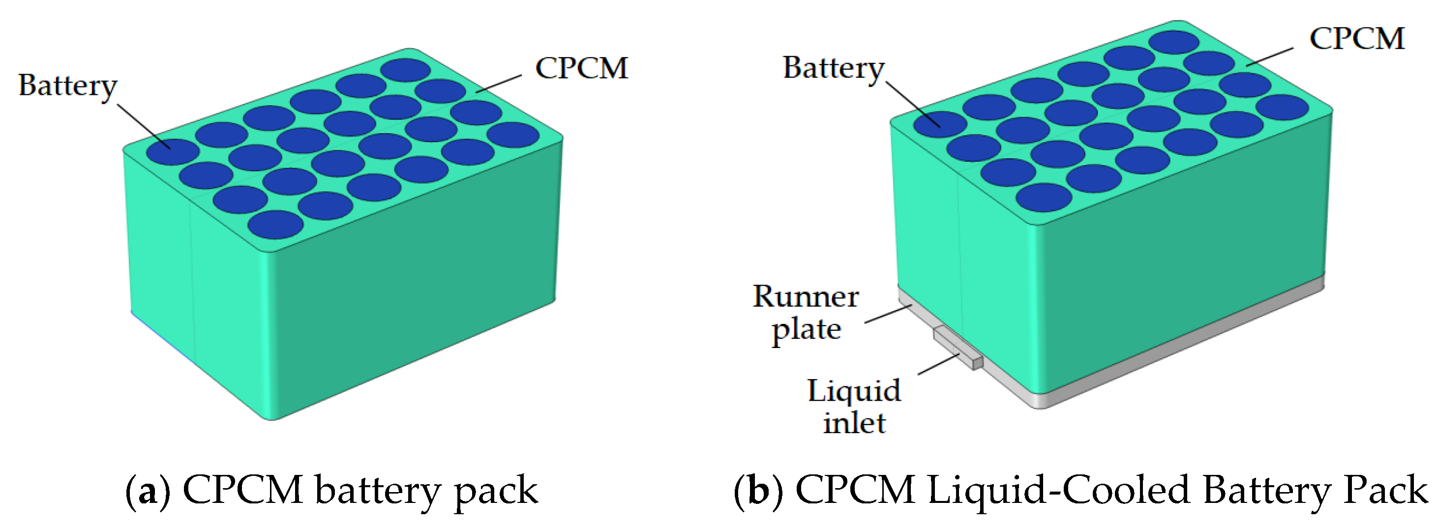
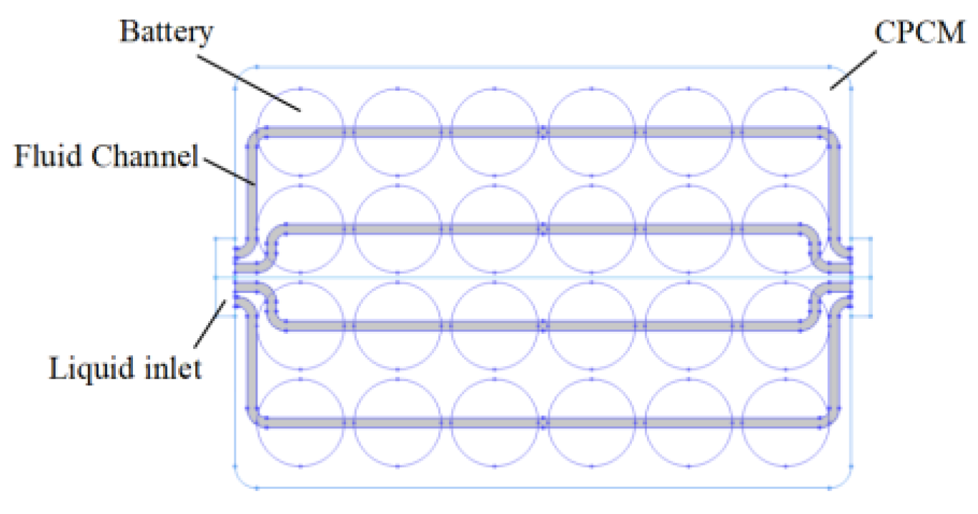
2.5. Battery Pack Layout Model

The spacing between batteries in the battery pack model is denoted as “x” mm, with specific values assigned as 0, 2, 4, and 6. The thickness of the aluminum shell used to encapsulate the CPCM is set to 1 mm, and this value is directly assigned within the COMSOL simulation software, not represented in the figure. Figure 2 illustrates the structure of the CPCM heat dissipation battery module.

2.6. Mesh Partitioning

Considering the computational complexity of the model, a symmetrical simplification method was adopted to calculate only the 6s2p battery packs on the half side. The simulation model mesh is selected as free tetrahedral meshes. The grid of the air-cooled battery pack and CPCM battery pack models includes “44,344” domain elements, 12,216 boundary elements, and 1432 edge elements. The grid of the CPCM liquid-cooled coupled battery pack model includes “76,246” domain elements, 18819 boundary elements, and 1895 edge elements. Mesh partitioning of the model is shown in Figure 3.

3. Results and Discussion

3.1. Lithium-Ion Battery Pack with Natural Convection Air Heat Dissipation

The maximum surface temperature of a lithium-ion battery pack only with natural air convection heat dissipation is investigated. The distance between battery cells is set to 2 mm. The battery module undergoes cyclic charging and discharging at a rate of 1–5 C, as shown in Figure 4.
The battery module begins from a fully charged state (i.e., SOC = 1) and undergoes charge and discharge cycles at a rate of 1–5 C. During battery charging, the lithium-ion battery produces an endothermic reaction. When the heat generated by the current flowing through the internal resistance is less than the heat absorbed by the lithium-ion battery, the battery temperature drops. The figure shows that under 1 C cyclic charging and discharging for 6000 s, the maximum surface temperature of the battery pack stays below 35 °C, within the optimal operating temperature range of 20–45 °C for lithium-ion batteries. At higher charging and discharging rates of 2–5 C, the maximum surface temperature of the battery pack exceeds the optimal operating temperature range of 45 °C. In particular, at a rate of 5 C, the maximum temperature reaches 75 °C, indicating a state of battery abuse. Moreover, with the increase in charging and discharging cycle time, the battery temperature continues to rise, which is likely to lead to the problem of thermal runaway, thus damaging the battery performance and safety. This suggests the need for effective thermal management of the battery pack to maintain the temperature within the appropriate range.

3.2. Lithium Ion Battery Pack with CPCM Heat Dissipation

After evaluating the natural convection air heat dissipation, this study refers to the comparative analysis by Wang and Du [10] regarding CPCM densities, thermal conductivity, latent heat, and phase change temperatures. A composite phase change material is prepared by mixing paraffin and expanded graphite in a 4:1 mass ratio. The six series four parallel battery packs with a battery spacing of 2 mm are wrapped for heat dissipation tests. Figure 5 illustrates the highest surface temperature curve of the paraffin-expanded graphite CPCM heat dissipation battery module under cyclic charging and discharging at a rate of 1–5 C.
The figure clearly demonstrates that the battery pack utilizing paraffin and expanded graphite for heat dissipation exhibits a considerable decrease in the maximum surface temperature compared to natural air convection heat dissipation. Under the same charging and discharging cycle of 6000 s, the maximum surface temperature of the battery has decreased by 2.22, 4.56, 14.00, 15.84, and 12.36 °C, respectively. The results demonstrate that using paraffin and expanded graphite in CPCM improves thermal conductivity. At charge rates of 1–4 C, CPCM exhibits increasing heat absorption. However, at 5 C, beyond the CPCM’s phase transition temperature, heat absorption decreases significantly. In addition, with the increase in charging and discharging cycle time, the battery temperature is still rising, and the ideal Thermal equilibrium state is not reached. Table 3 displays the maximum surface temperature of a lithium-ion battery pack with paraffin and expanded graphite CPCM heat dissipation at 1–5 C.

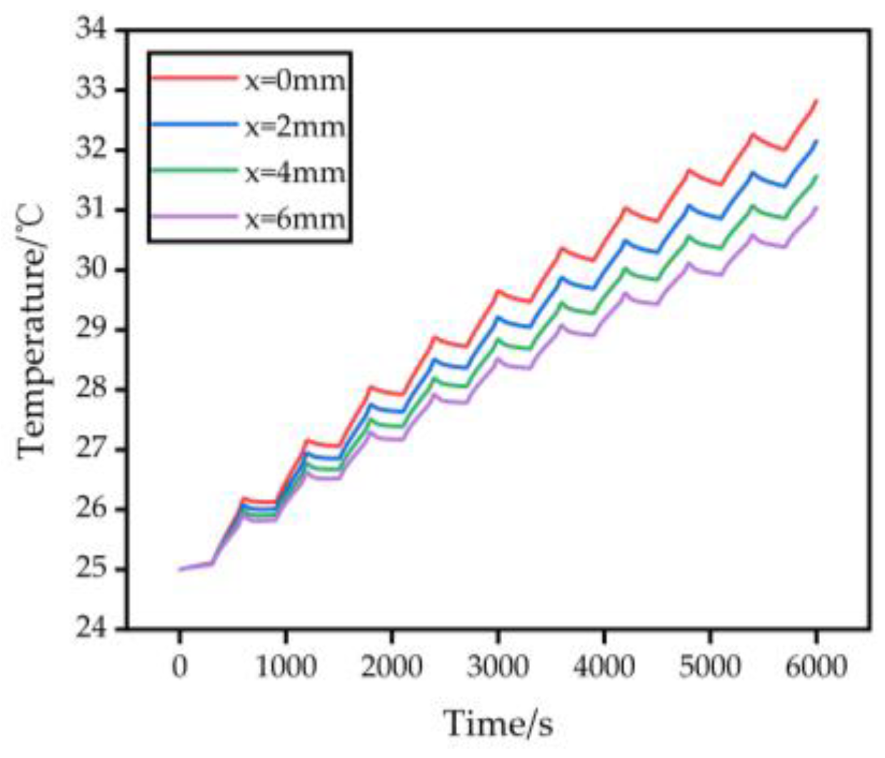
3.3. Effect of Varying Battery Spacing on Temperature Rise of Battery Pack Models

Figure 6 illustrates the surface temperature distribution of the battery module with CPCM heat dissipation at a 1 C discharge rate for different battery spacing values (x = 0, 2, 4, and 7 mm); Figure 7 displays the highest surface temperature curve of the battery pack over time at a 1 C discharge rate with varying cell spacing. Table 4 presents the maximum surface temperature of battery modules at a 1 C discharge rate for different battery spacing. Figure 8 shows the effect of different battery spacing on the specific and volumetric energy density of the battery pack.
The maximum surface temperatures of the battery pack are observed to be 32.82, 32.15, 31.56, and 31.04 °C for battery spacing of 0, 2, 4, and 6 mm, respectively. When the battery spacing is increased from 0 mm to 2 mm, the maximum surface temperature of the battery pack decreased by 0.66 °C. However, when the spacing is further increased from 4 mm to 6 mm, the maximum surface temperature of the battery pack only decreases by 0.52 °C. Increased spacing between battery cells improves cooling effectiveness, but the rate of improvement diminishes. Moreover, as the battery spacing gradually increases, the specific energy density and volume density of the battery also slightly decrease. Considering factors such as battery weight, volume, energy density, and cost, it is more appropriate to set the battery spacing to 0 or 2 mm.

3.4. Lithium-Ion Battery Pack with CPCM Liquid Cooling Heat Dissipation

To enhance the heat dissipation of CPCM and address the issue of heat dissipation after complete melting, this study develops a heat dissipation model that incorporates paraffin-expanded graphite CPCM and liquid cooling through a flow field. The length and width of the runner board are the same as the bottom surface of the battery module. The thickness of the runner plate is 10 mm. The runner plate is made of aluminum and has four runners each with a cross-sectional dimension of 2 mm by 2 mm and a length of 4 mm at the inlet and outlet. The flow channel is 4 mm away from the bottom of the battery. Assuming that the bottom of the CPCM battery pack seamlessly contacts the flow channel plate. Water is used as a coolant, with an inlet flow rate of 0.001 m/s. The cross-sectional area of the flow field model is depicted in Figure 9.
Based on the selection of a battery spacing of 0 or 2 mm, 1–5 C cyclic charging and discharging tests are performed on the CPCM liquid cooling coupling model. Figure 10 illustrates the highest surface temperature curve of the paraffin expanded graphite CPCM liquid-cooled coupled heat dissipation battery module during cyclic charging and discharging at a rate of 1–5 C.
Figure 10a shows that, at 1–5 C, the battery pack with CPCM liquid cooling coupling achieves a lower maximum surface temperature compared to CPCM heat dissipation alone. With a constant battery spacing of x = 2 mm, the maximum surface temperature decreases by 2.51, 5.28, 0.57, 5.92, and 10.13 °C, respectively. Liquid cooling coupling greatly improves the heat absorption effect of CPCM. This study attempts to reduce the battery spacing to 0 mm. When the charging and discharging rate is between 1–3 C, the maximum temperature of the battery can be maintained below 45 °C. Even with high-rate charging and discharging at 5 C, the maximum temperature of the battery can be maintained below 60 °C. Figure 10b illustrates the effectiveness of CPCM and liquid cooling in reducing the battery size while ensuring the cooling effect. Table 5 presents the maximum surface temperature of the CPCM liquid-cooled battery pack at 1–5 C.
At the same time, compare the CPCM liquid cooling coupling heat dissipation with the battery pack with only channel plate heat dissipation. Figure 11 and Table 6 show a comparison of the surface temperature difference of the battery. It can be seen that coupling CPCM with liquid cooling can improve the cooling effect on the basis of CPCM heat dissipation, while also improving the temperature uniformity of the battery on the basis of liquid cooling heat dissipation.

4. Conclusions

This study develops a paraffin-expanded graphite CPCM liquid cooling coupled heat dissipation model. It analyzes the heat absorption effect and studies the impact of different battery spacing on surface temperature. The optimal battery layout for the CPCM model is determined, and a CPCM liquid cooling coupled heat dissipation model is established. The findings are summarized as follows.
(1)
The addition of expanded graphite to paraffin in the CPCM enhances its thermal conductivity, resulting in improved heat absorption during the sensible heat stage. Under the 1–5 C charge-discharge rate, the maximum surface temperature of the battery pack using the paraffin expanded graphite CPCM heat dissipation model is lower by 2.22, 4.56, 14.00, 15.84, and 12.36 °C compared to the air cooling heat dissipation model.
(2)
Increasing the spacing between individual batteries in the battery pack can provide a certain cooling effect. However, the cooling efficiency improvement diminishes as the spacing increases. Therefore, it is crucial to consider cooling requirements, battery pack size, and cost in order to determine the optimal spacing.
(3)
CPCM liquid cooling coupled with heat dissipation effectively reduces the maximum surface temperature of the battery pack at a charging and discharging rate of 1–5 C. The temperature decrease is 2.51, 5.28, 0.57, 5.92, and 10.13 °C. This study attempts to reduce the battery spacing to 0 mm. When the charging and discharging rate is between 1–3 C, the maximum temperature of the battery can be maintained below 45 °C. Thus, CPCM liquid cooling can reduce battery size while ensuring heat dissipation efficiency.
(4)
By coupling CPCM with liquid cooling, the cooling effect can be improved on the basis of CPCM heat dissipation, while also improving the temperature uniformity of the battery on the basis of liquid cooling heat dissipation. Moreover, this structure places the flow channel plate below the CPCM battery pack, which is simpler than the structure of inserting pipes or liquid cooling plates in the middle of the battery, making it easy to install, repair, and replace, and reducing costs. This study optimizes the cooling effect, temperature uniformity, structural size, and cost of the lithium-ion battery pack thermal management system.

Author Contributions

Conceptualization, C.D., Y.W. and Z.W.; methodology, C.D., Y.W. and Z.W.; software, C.D. and Y.W.; validation, C.D. and Y.W.; formal analysis, C.D.; investigation, C.D.; resources, C.D.; data curation, C.D., Y.W. and Z.W.; writing—original draft preparation, C.D. and Y.W.; writing—review and editing, C.D. and Z.W.; visualization, C.D. and Y.W.; supervision, C.D. and Z.W.; project administration, C.D.; funding acquisition, C.D. All authors have read and agreed to the published version of the manuscript.

Funding

This work was financially supported by the National Natural Science Foundation of China, grant number 51975434; Foshan Xianhu Laboratory of the Advanced Energy Science and Technology Guangdong Laboratory, grant number XHD2020-003; Key R & D project of Hubei Province, China, grant number 2022BAA074.

Institutional Review Board Statement

Not applicable.

Informed Consent Statement

Informed consent was obtained from all subjects involved in the study.

Data Availability Statement

Not applicable.

Conflicts of Interest

The authors declare no conflict of interest.

References

  1. Höök, M.; Tang, X. Depletion of fossil fuels and anthropogenic climate change—A review. Energy Policy 2013, 52, 797–809. [Google Scholar] [CrossRef] [Green Version]
  2. Sovacool, B.K. Valuing the greenhouse gas emissions from nuclear power: A critical survey. Energy Policy 2008, 36, 2950–2963. [Google Scholar] [CrossRef]
  3. Abas, N.; Kalair, A.; Khan, N. Review of fossil fuels and future energy technologies. Futures 2015, 69, 31–49. [Google Scholar] [CrossRef]
  4. Gong, H.; Wang, M.Q.; Wang, H. New energy vehicles in China: Policies, demonstration, and progress. Mitig. Adapt. Strateg. Glob. Change 2013, 18, 207–228. [Google Scholar] [CrossRef]
  5. Li, L.Y. Current status and development trend of Li-ion batteries for new energy vehicles in China. Chin. J. Power Sources 2020, 44, 628–630. [Google Scholar]
  6. German, R.; Delarue, P.; Bouscayrol, A. Battery pack self-heating during the charging process. In Proceedings of the 2018 IEEE International Conference on Industrial Technology (ICIT), Lyon, France, 20–22 February 2018; IEEE: Piscataway, NJ, USA, 2018. [Google Scholar]
  7. Zhang, Y.; Guo, X.; Xue, W.; Zhang, Z.; Liang, J.; Wang, H. Research Progress on multi-scale thermal safety of lithium-ion power battery system. Chin. J. Beijing Univ. Aeronaut. Astronaut. 2021, 49, 31–44. [Google Scholar] [CrossRef]
  8. Chung, Y.H.; Jhang, W.C.; Chen, W.C.; Wang, Y.W.; Shu, C.M. Thermal hazard assessment for three C rates for a Li-polymer battery by using vent sizing package 2. J. Therm. Anal. Calorim. 2016, 127, 809–817. [Google Scholar] [CrossRef]
  9. Pesaran, A.A. Battery Thermal Models for Hybrid Vehicle Simulations. J. Power Sources 2002, 110, 377–382. [Google Scholar] [CrossRef]
  10. Zichen, W.; Changqing, D. A comprehensive review on thermal management systems for power lithium-ion batteries. Renew. Sustain. Energy Rev. 2021, 139, 110685. [Google Scholar] [CrossRef]
  11. Liu, L.; Zhang, H.-Q.; Guan, C. Progress in Application of Phase Change Materials in Thermal Management Systems for Power Battery. Chin. Bull. Chin. Ceram. Soc. 2016, 35, 150–153. [Google Scholar] [CrossRef]
  12. Ma, X.; Zou, D.; Liu, X.; Li, L. Research progress on phase change material for power battery thermal management. Chin. New Chem. Mater. 2017, 45, 23–25. [Google Scholar]
  13. Zhang, J. Research on Power Batteries Thermal Management Technology Based on PCM. Master’s Thesis, Chinese Guangdong University of Technology, Guangzhou, China, 2013. [Google Scholar]
  14. Rami Sabbah, R.; Kizilel, R.; Selman, J.R.; Al-Hallaj, S. Active (air-cooled) vs. passive (phase change material) thermal management of high power lithium-ion packs: Limitation of temperature rise and uniformity of temperature distribution. J. Power Sources 2008, 182, 630–638. [Google Scholar] [CrossRef]
  15. Wang, Z.; Zhang, Z.; Jia, L.; Yang, L. Paraffin and paraffin/aluminum foam composite phase change material heat storage experimental study based on thermal management of Li-ion battery. Appl. Therm. Eng. 2015, 78, 428–436. [Google Scholar] [CrossRef]
  16. Zhang, Z.; Zhang, N.; Peng, J.; Fang, X.; Gao, X.; Fang, Y. Preparation and thermal energy storage properties of paraffin/expanded graphite composite phase change material. Appl. Energy 2012, 91, 426–431. [Google Scholar] [CrossRef]
  17. Jiang, G.; Huang, J.; Fu, Y.; Cao, M.; Liu, M. Thermal optimization of composite phase change material/ expanded graphite for Li-ion battery thermal management. Appl. Therm. Eng. 2016, 108, 1119–1125. [Google Scholar] [CrossRef]
  18. Rao, Z.; Huo, Y.; Liu, X.; Zhang, G. Experimental investigation of battery thermal management system for electric vehicle based on paraffin/copper foam. J. Energy Inst. 2015, 88, 241–246. [Google Scholar] [CrossRef]
  19. Wei, Z.-H.; Xu, S.-C.; Li, Z.; Lin, C.; Chang, G. Research on active-passive thermal management system of LiFePO4 battery pack. Chin. J. Power Sources 2016, 40, 4. [Google Scholar]
  20. Huang, J.H.; Liu, Z.Q.; Cao, M.; Jiang, G.; Yan, Q. Thermal management ofbattery pack based on phase change material and liquid cooling coupling. Chin. J. Power Sources 2019, 43, 4. [Google Scholar]
  21. Liu, Z.; Huang, J.; Cao, M.; Jiang, G.; Yan, Q.; Hu, J. Experimental study on the thermal management of batteries based on the coupling of composite phase change materials and liquid cooling. Appl. Therm. Eng. Des. Process. Equip. Econ. 2021, 185, 116415. [Google Scholar] [CrossRef]
  22. Bernardi, D.; Pawlikowski, E.; Newman, J. A General Energy Balance for Battery Systems. J. Electrochem. Soc. 1985, 132, 5. [Google Scholar] [CrossRef] [Green Version]
Figure 1. Battery pack model.
Energies 16 05260 g001
Figure 2. Top View of Battery Pack Model.
Energies 16 05260 g002
Figure 3. Mesh Partitioning of the Model.
Energies 16 05260 g003
Figure 4. Maximum Surface Temperature of Air-Cooled Battery Pack.
Energies 16 05260 g004
Figure 5. Maximum Surface Temperature of the Battery Pack Wrapped in CPCM.
Energies 16 05260 g005
Figure 6. Temperature Distribution of Battery Pack with Different Battery Spacing.
Energies 16 05260 g006
Figure 7. Maximum Surface Temperature with Different Battery Spacing.
Energies 16 05260 g007
Figure 8. Specific and Volumetric Energy Densities with Different Battery Spacing.
Energies 16 05260 g008
Figure 9. Cross Section of Flow Field Model.
Energies 16 05260 g009
Figure 10. Maximum Surface Temperature of the Battery Pack with CPCM Liquid Cooling Model.
Energies 16 05260 g010
Figure 11. A Comparison of the Surface Temperature Difference of the Battery.
Energies 16 05260 g011
Table 1. Specification Parameters of Battery.
ParameterValue
Capacity/Ah3.4
Diameter/mm18
Height/mm65
Weight/g46
Nominal Voltage/V3.7
Discharge Cut-off Voltage/V2.5
Internal Resistance/mΩ35
Radial Thermal Conductivity/W·(m·K)−10.897
Axial Thermal Conductivity/W·(m·K)−129.557
Density/kg·m−32055.2
Specific heat capacity/J·(kg·K)−11399.1
Table 2. Basic Parameters of CPCM.
ParameterValue
Melting temperature/°C42.98
melting range/°C2
thermal conductivity/W·(m·K)−17.85
Density/kg·m−3714
Specific heat capacity/J·(kg·K)−12500
latent heat/kJ·kg−1181
Table 3. The Maximum Surface Temperature of the CPCM Battery Pack.
Rate of Charge and Discharge/C12345
Maximum temperature of air-cooled battery pack/°C34.3647.4058.2767.4675.42
Maximum temperature of
CPCM battery pack/°C
32.1542.8444.2751.6163.06
Maximum temperature drop/°C2.224.5614.0015.8412.36
Table 4. Maximum Surface Temperature of Battery Packs with Different Battery Spacing.
Battery Spacing/mm0246
Maximum surface temperature of battery pack/°C32.8232.1531.56 31.04
Table 5. Maximum Surface Temperature of the Battery Pack of CPCM Liquid-cooled Coupling Model.
Rate of Charge and Discharge/C12345
Maximum temperature of battery pack/°CCPCM32.1542.8444.2751.6163.06
CPCM-Liquid (x = 2 mm)29.6437.5643.7045.6952.93
CPCM-Liquid (x = 0 mm)30.4139.1644.2248.8457.71
Maximum temperature dropx = 2 mm2.515.280.575.9210.13
x = 0 mm1.743.680.052.775.35
Table 6. A Comparison of the Surface Temperature Difference of the Battery.
Rate of Charge and Discharge/C12345
Temperature difference of
liquid cooled battery pack/°C
1.05 3.07 4.89 6.57 8.35
Temperature difference of CPCM
and liquid cooled battery pack/°C
0.79 2.12 2.94 5.65 5.32
Temperature difference drop/°C0.26 0.95 1.95 0.923.03
Disclaimer/Publisher’s Note: The statements, opinions and data contained in all publications are solely those of the individual author(s) and contributor(s) and not of MDPI and/or the editor(s). MDPI and/or the editor(s) disclaim responsibility for any injury to people or property resulting from any ideas, methods, instructions or products referred to in the content.

