Review

Effect of Regenerative Braking on Battery Life

1
Automotive Research Centre, Vellore Institute of Technology, Vellore 632014, India
2
School of Mechanical Engineering, Vellore Institute of Technology, Vellore 632014, India
3
Department of Thermal Processes, Air Protection and Waste Management, Cracow University of Technology, 31-155 Cracow, Poland
4
Department of Energy, Cracow University of Technology, 31-864 Cracow, Poland
*
Author to whom correspondence should be addressed.
Energies 2023, 16(14), 5303; https://doi.org/10.3390/en16145303
Submission received: 13 June 2023 / Revised: 3 July 2023 / Accepted: 6 July 2023 / Published: 11 July 2023
(This article belongs to the Section J1: Heat and Mass Transfer)

Abstract

:
It is a well-known fact that automotive industries in every country are shifting towards electric vehicles (EVs) and in the days to come it is expected that the industry will become dominated by them, along with hybrid electric vehicles (HEVs). Unfortunately, the acceptance of EVs for mobility is affected by its poor range per charge. Thus, energy optimization and waste energy recuperation are currently in need. A promising method to recover energy that is lost during vehicle deceleration is regenerative braking, which extends the range of a vehicle by recovering the kinetic energy from braking and using it to recharge the battery. However, the intensity of the charging–discharging rate and the operating temperature of lithium–ion (Li–ion) batteries make them vulnerable to failure, making the rate of current delivered to the battery by regenerative braking a serious concern. Therefore, the focus of this review article is on how regenerative braking affects battery life and the precautions being taken to safeguard the battery against increased charge during regenerative braking. In this review paper, various research articles are referred to in order to examine how regenerative braking affects battery life. It is concluded that charging current obtained from long-term regenerative braking is the prominent factor in battery deterioration, regardless of the current intensity. Additionally, the rate of lithium plating is increased if the temperature and state of charge (SOC) are outside of the ideal range. By lowering the depth of discharge (DOD) and using shorter recharging times, higher levels of regenerative braking will extend a battery’s lifecycle even at high SOC and temperature.

1. Introduction

In urban driving situations, conventional braking systems discard the kinetic energy of the vehicle as heat in the braking system. A regenerative braking system (RBS) works by converting kinetic energy to electric energy/mechanical work, which is then stored in a battery/ultracapacitor or a fly wheel. RBS cannot substitute or replace the mechanical braking system in a vehicle, though it is used to decelerate the vehicle to a certain level during which the energy can be tapped. Based on the rate of application of the brake (travel of brake pedal), the level of regenerative braking is decided by the controller. EVs use this harvested energy to accelerate the vehicle immediately after braking or for charging the battery pack, ultracapacitor (UC), or supercapacitor (SC). Therefore, regenerative braking leads to an increase in the range of electric vehicles by 8 to 25%. The maximum current that a battery can manage depends on the operating voltage, the motor’s speed, the battery’s internal resistance, and the armature resistance. Researchers have examined several regenerative braking systems (RBS) or kinetic energy recovery systems (KERS) for electric, hybrid, and internal combustion engine vehicles with various energy storage systems (mechanical, electrical, chemical, and hydraulic), and have determined whether they are suitable for retrofit application on production vehicles. During urban driving, as much as one third to one half of the energy is wasted in braking. Figure 1 shows the conceptual diagram of a regenerative braking system used in HEVs and EVs.
The voltage adaptation between the starter/generator and/or battery is often carried out by proper power converters, which can ensure an improvement in efficiency and in the bidirectional flow of energy. Because of their inferior energy density compared with batteries, the application of supercapacitors as a novel storage solution in electric cars is still restricted. Flywheels, which are purely mechanical systems, are also used as energy recovery systems in trains, trucks, and sports vehicles. The use of an SC or UC is much more convenient than the use of a flywheel when managing severe acceleration and braking, particularly when compared with an SC or UC paired with a flywheel as a supplementary energy storage device on a pure electric car. Recently, supercapacitors have also begun to be developed for use in railway systems, where it is noticeable that energy consumption efficiency has improved and the peak power demand and operating costs in railway substations have decreased.
The implementation of modern power electronic components such as ultracapacitors, DC–DC converters (buck–boost), and flywheels have improved the performance of regenerative braking systems. A flywheel is utilized to improve energy recovery mechanically through the car’s wheel, while the buck–boost converter maintains power management in the regenerative braking system for enhanced acceleration [1]. The ultracapacitor improves the transient state of the car during its starting, provides a smoother charging characteristic for the battery and also enhances the overall performance of the EV system. Furthermore, this technology allows the vehicle to accelerate and decelerate faster with less energy loss and less degradation of the primary battery pack [2]. By using the ultracapacitors with a bidirectional IGBT DC–DC converter, an improvement in the efficiency of the vehicle can be achieved through regenerative braking.
Storing RBS energy or charging the battery depends on the state of charge of the battery, which indicates how much charge remains. Accurate measurement of SOC leads to a longer battery life and the prevention of premature battery failure. Additionally, a reliable and accurate SOC estimation is essential for effective EV operation. However, due to its reliance on different variables, including battery age, the surrounding environment, and numerous unknown elements, SOC estimation is a challenging process. The model-based and data-driven techniques have been used in recent SOC estimate methods [3]. Model-based methods aim to model battery behavior by including many aspects within complex mathematical equations to accurately estimate the SOC, whereas data-driven methods use complex algorithms to learn a battery’s behavior from a vast quantity of measured battery data. The classifications of SOC, such as the bookkeeping, adaptive, and hybrid methods of estimation, are explained in terms of their drawbacks and estimation errors [4].
Another important battery parameter that dictates an RBSs energy recovery is the state of health (SOH)—a very important parameter for estimating battery life. In an intelligent battery management system (BMS), state of health (SOH) prediction in Li–ion batteries is critical. The occurrence of the capacity regeneration phenomenon provides a significant obstacle in precisely estimating a battery’s SOH [5,6]. Batteries must be controlled more efficiently to maximize driving range, optimal power use, longevity, and battery performance and to ensure safe operation. Improper battery management may result in safety-related concerns such as increased battery ageing and overheating, concerns which might in turn lead to an explosion. SOH refers to the current condition of an existing battery’s ability to offer specified performance as compared with its ability to have given that specific performance when it was in its initial state. The SOH of a battery is calculated by dividing the actual capacity by the nominal capacity [7]. To predict the SOH of Li–ion batteries, direct assessment, adaptive, and data-driven approaches, as well as other methods [5,7], are implemented.
Today, RBSs for most electric vehicles are based on batteries, which offer the optimal energy management of energy storage systems. This review article introduces the RBS and primarily concentrates on the storing of recuperated energy in Li–ion batteries and the effect of the rate of storage of this energy on the life of the battery pack. Thus, parameters such as SOC and SOH are explained in detail in terms of the effective storage of energy. Figure 2 shows the layout of this paper.

2. Literature Review

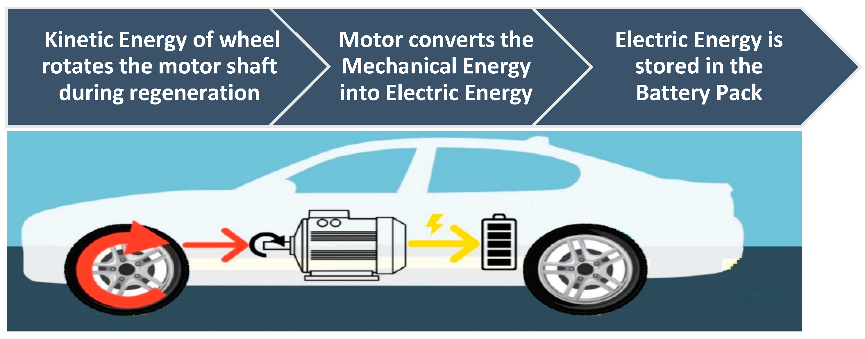
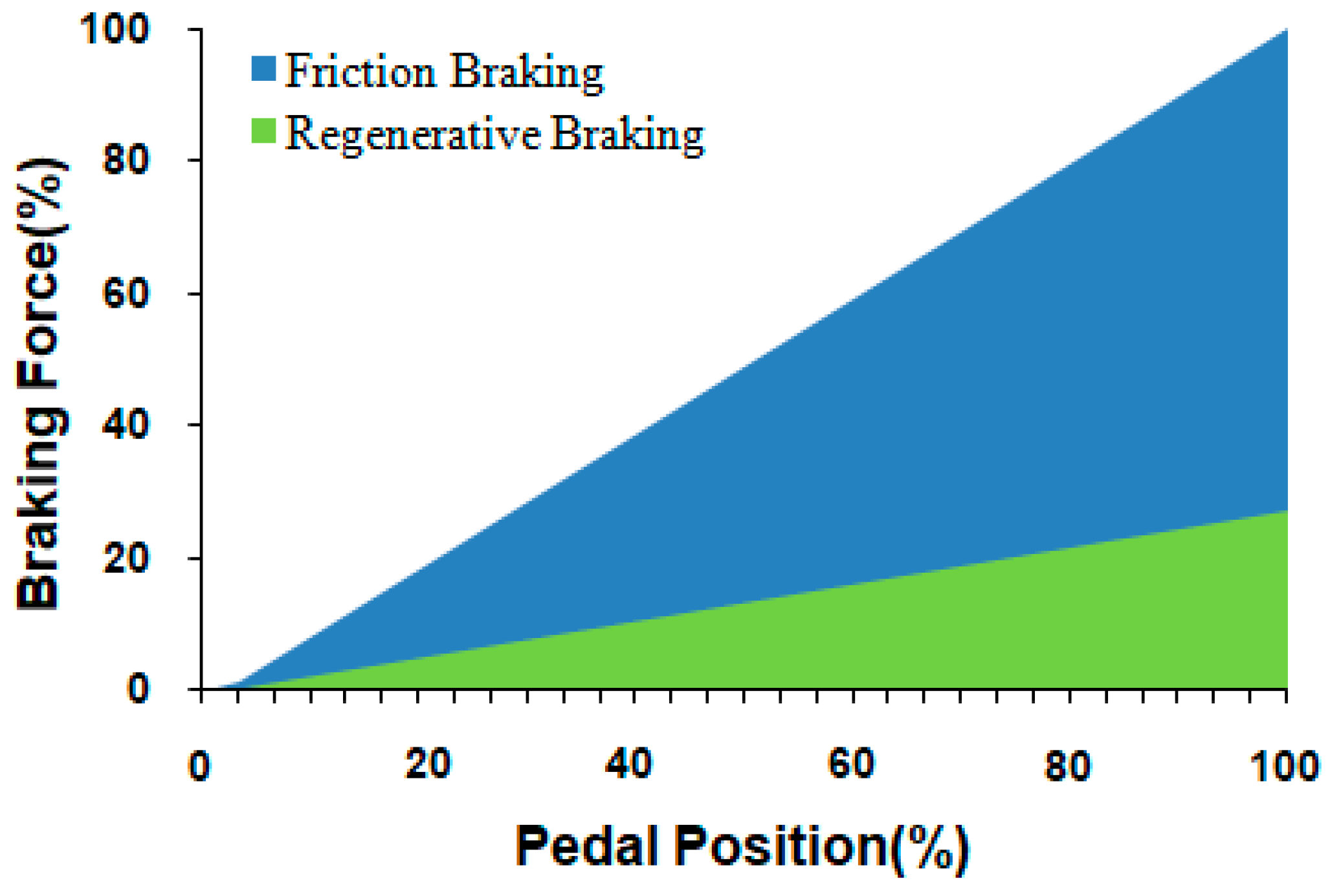
2.1. Regenerative Braking

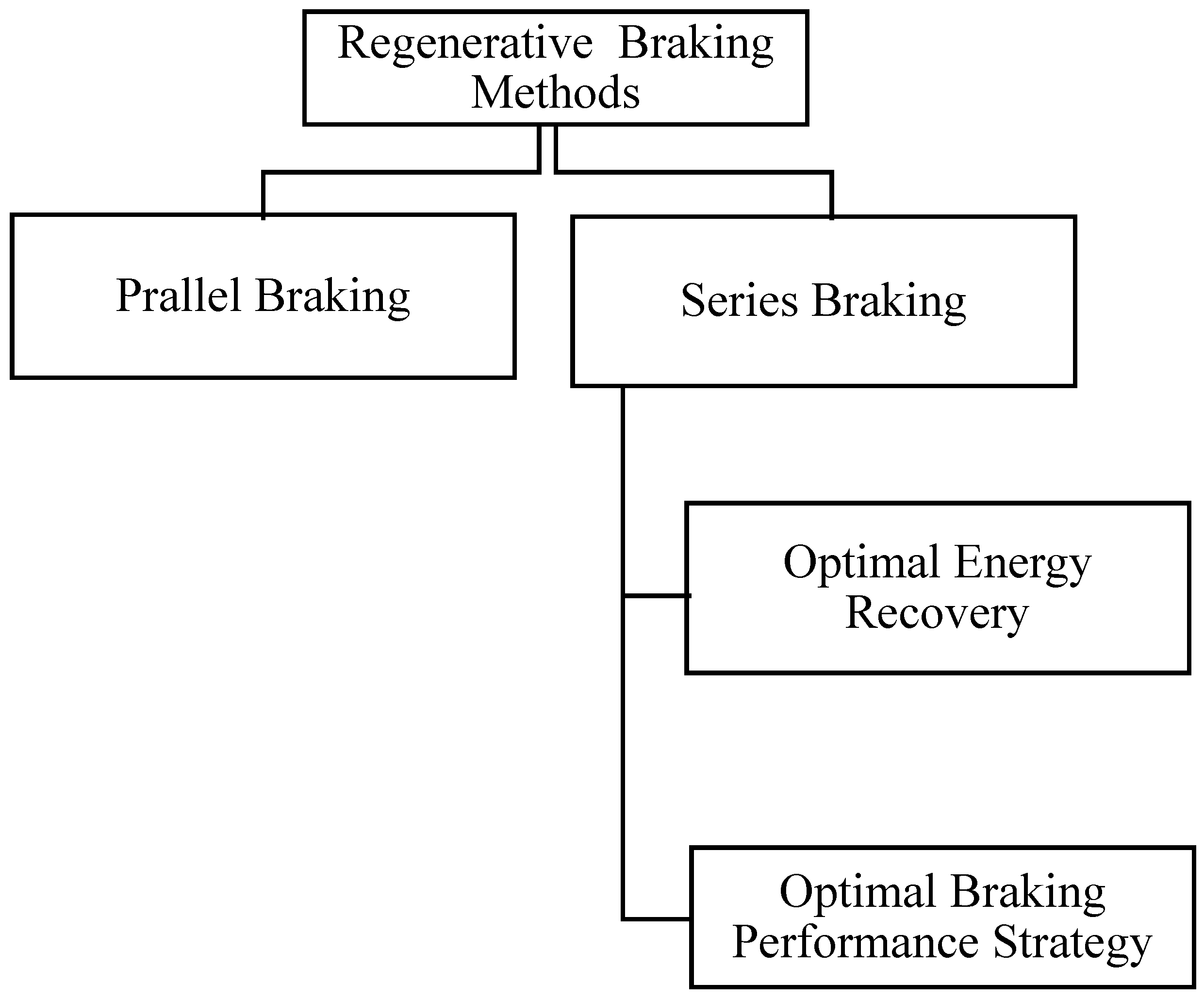
2.1.1. Different Regenerative Braking Strategies

A regenerative braking system (RBS) discussed by Cikanek and Bailey [8] for parallel hybrid electric vehicles (PHEV) performs energy recovery based on vehicle attributes. The authors calculated the maximum front and rear brake forces using slopes and intercepts. Their RBS algorithm was modelled using an analogue MATRIXx algorithm and then discretized by developing the code using MATRIXxAutocode. At first, a connection was created between hydraulic brake pressure and electric brake torque (torque generated by regenerative braking). The regenerative braking torque’s magnitude was finally calculated as a function of motor speed against torque. The engine is detached from the drive wheels during braking to reduce engine frictional losses. Regenerative braking is carried out using a high-efficiency, single-gear, direct-drive transaxle. The removal of regenerative brake torque at the drive wheels (engine-driven wheel) improved energy recovery and braking performance. In a similar simulation study on HEV, the results of baseline (without RBS) and proposed regenerative braking strategies are compared in terms of HEV system behavior, such as overall fuel economy and emissions characteristics [9]. The results show improved performance, efficiency, and reliability at reduced cost.
Figure 3 shows a layout that represents the methods of regeneration of braking.
Gao et al. [10] assumed that, for ideal wheel braking distribution, deceleration should be less than 0.1 g and regenerative applied only on the front wheels; otherwise, the ideal braking force curve is to be followed. In braking with optimal energy recovery, the optimal regenerative energy can be recovered by distributing the braking forces on the front and rear axles to avoid locking either of the axles. The maximum deceleration is equal to the adhesive coefficient when the deceleration (j/g) is greater than or equal to the adhesive coefficient of the tire–ground contact (μ). According to the required braking force and the quantity of available regenerative braking, the front axle either receives combined regenerative and mechanical braking force or solely regenerative braking. For this strategy, more braking force is allocated to the front wheels, given that the front wheels are never locked earlier than the rear wheels. The braking distribution is divided according to the r-lines and f-lines, where both lines depict the ground braking forces on the rear and front wheels, respectively, when they are locked [11].
Solely regenerative braking is used in parallel braking when the required deceleration is less than 0.1 g, and solely mechanical braking is used when the required deceleration is larger than 0.7 g. Both the mechanical and regenerative brake systems are operable between 0.1 and 0.7 g. Solely regenerative braking forces must be controlled by the electric motor controller in accordance with the vehicle’s motor speed and deceleration. Again, in the latest paper [11], parallel hybrid braking is described when the wheel speed is lower than the given threshold and total mechanical braking takes place.
Figure 4 and Figure 5 show graphical representations of series and parallel regeneration braking, respectively, and denote the relation between the braking force versus the pedal. When the wheel speed is above the threshold, and the desired vehicle deceleration is less or above than the required value, total electric regenerative braking or combined mechanical and regenerative braking takes place, respectively. Furthermore, Gao et al. [11] have presented a new optimal braking performance strategy (2007). For their strategy, when the required total braking force is less or more than the capacity of the electric motor, then either total regenerative braking or combined electric and mechanical braking is applied, respectively. The total mechanical braking is applied by following the specified I-curve in the given graph. This could lead to a 12% reduction in fuel usage for HEV powertrains [12].
An integrated braking system has been introduced that combines regenerative braking, automatic control force distribution and ABS, and in which the braking strategy is applied according to the vehicle speed and maximum motor torque [13]. If the braking torque is less than the maximum motor torque, then regenerative braking is applied, and if it is greater than the maximum motor torque, then combined regenerative braking and mechanical braking takes place, i.e., a parallel hybrid braking strategy [11] that considers motor braking torque. The simulation results show that more than 60% of braking energy can be recovered when only the front wheels are available for regenerative braking. In a panic-stop situation, a regenerative ABS reaction is preferable. An enhanced hybrid ABS solution for electrified powertrain applications might be obtained by assessing the reliability, cost, and sizing issues of electric drives and the required energy storage device for regenerative ABS [14]. Different strategies of RBS have been compared in order to maintain vehicle stability and energy recovery. A basic regenerative braking approach was presented according to the battery and motor’s charge and discharge characteristics. The strategy considered the required braking torque, the motor’s rated braking torque, and the braking torque limit, and was shown to be able to maximize the motor’s braking torque. The proposed method is stated to generate more energy than a parallel technique that enhances the battery state of charge (SOC) and regenerates energy more efficiently [15]. By using the optimal CVT speeds ratio control algorithm for regenerative braking, an increase of 8% in recuperated energy for the federal urban driving schedule was observed [16]. For safety-critical driving circumstances, Qiu et al. [17] aimed to address the EV control method for regenerative braking. The appropriate braking torque for ABS control of an electric vehicle was computed using phase plane theory after presenting the RBS strategy. Then, an allocation control was proposed, in which the required optimal brake torque is divided into two halves and distributed between the mechanical and regenerative brakes. Furthermore, two metrics for measuring the contribution of regeneration braking to energy efficiency during the deceleration braking process are outlined, these form a ‘serial control strategy’, which is similar to an optimizing braking performance strategy [11]. The findings of an ice road test indicate that the serial control approach increased energy efficiency and that it has contribution ratios to stable and dynamical breaking energy efficiencies of up to 58.56% and 69.74%, respectively.

2.1.2. Combined Regenerative Braking and Fuzzy Logics System

Nian et al. [18] used proportional–integral–derivative (PID) controller for a brushless direct–current (BLDC) motor and a fuzzy logic controller for the distribution of braking force to make RBS adaptive to the BLDC motor. From this, the distribution of the braking force and BLDC motor control is made easier. The state of charge (SOC), and braking force, are currently used to produce the braking torque as input variables of the fuzzy controller and are simulated in the Simulink. The simulated performance of RBS was determined to be similar to the practical results, and so the system optimized the regenerative braking system and extended the driving distance. However, in terms of steady-state tracking error and response speed, experimental results reveal that an H∞ robust controller that is actuated by a permanent DC motor outperforms a typical PID controller [19]. Additionally, H∞ can be optimized by integrating the sliding phase and the hitting phase, creating the parameters of a sliding mode controller. Furthermore, the system’s gain matrix ensures the system’s robust stability and disturbance rejection specifications [20]. The regenerative braking controller comprises a back propagation neural network (BPNN), a radial basis function NN (RBFNN), and a sliding mode controller (SMC or NNSMC). To avoid whippings, the BPNN is employed to modify the switching gain of the SMC online adaptively. The RBFNN is used to identify and predict parameters in a system. The experimental results show that NNSMC further outperforms standard SMC in terms of response speed, steady-state tracking error, and regenerative-braking disturbance resistance. It can also recover more energy, extend battery life, and boost driving range by around 6% [21]. If an NN-based PID controller is used, then the driving range is increased by 5.3% [22]. An NN-based switching reluctance motor (SRM) drive control technique has also been developed to meet regenerative braking requirements. However, iron loss at high rotor speed has resulted in lower energy recovery efficiency at lower braking torque [23].
Xu et al. [24] implemented the concept of fuzzy logic in an RBS to reduce energy consumption. To prevent cars from experiencing wheel lock and slippage while braking, the ideal energy recovery distribution curve distributes braking power between the front and rear wheels [11]. The allocation of friction braking force and regenerative braking force is then calculated to maximize energy recovery efficiency using a fuzzy RBS that incorporates the driver’s braking force command, vehicle speed, SOC [25], and battery temperature. Experiments on an FWD LF620 prototype EV confirmed the feasibility, controllability and effectiveness of fuzzy RBS [26]. The maximum driving range increased by 25.7% as compared with non-RBS systems. Additionally, the fuzzy RBS saved an additional 11% of the battery capacity energy, thus resulting in a 22% increase in overall energy efficiency. Peng et al. [27] presented a combined braking control strategy (CBCS) that synchronized hydraulic and regenerative braking systems according to an HEV braking torque distribution. The control system meets the criteria of a vehicle’s longitudinal braking performance while also recharging the battery with greater regenerative energy. A logic threshold control strategy (LTCS) and fuzzy logic control strategy (FCS) adjusted the hydraulic braking torque and regenerative braking torque, respectively, in real-time conditions. The control strategy ensured high regenerative efficiency and good braking performance, even when emergency braking is necessary on roads with low adhesion coefficients. Based on the calculation of the μ and using a fuzzy logic estimation approach, Paul et al. [28] proposed a brake force distribution (BFD) approach for an electric vehicle with all-wheel drive (AWD) and a single electric motor. The suggested method finds the best BFD to maximize regenerative power while braking for a particular vehicle’s speed and deceleration need by taking into consideration motor efficiency and available speed reduction ratios. Preliminary test findings with a prototype car serve as confirmation for simulation evaluations, showing the suggested tire–road friction estimation-based BFD optimization technique greatly increases braking energy recovery.

2.1.3. Other Regenerative Braking System Strategies

Zhang et al. [29] have also introduced three distinct approaches for an EV, including the maximum regeneration efficiency approach, the good-pedal-feel strategy, and the coordination strategy. MATLAB/Simulink models of an EV car’s regenerative and frictional blending brakes were created and used to examine the control effects and regeneration efficiency of the control schemes in a typical deceleration process. The practical and modelling results show that the maximum regeneration efficiency method is a compromise of brake comfort and safety. In terms of brake comfort and regeneration efficiency, the good-pedal-feel approach and coordination strategy outperform the maximum regeneration efficiency strategy. For the ECE driving cycle, the developed regenerative braking technology increased fuel economy by more than 25%. Ahn et al. [30] propounded the incorporation of an electronically controlled brake subsystem that independently distributes the braking forces to all four wheels for HEV electro-mechanical brake (EMB) systems. The internal combustion (IC) engine, electric motor, battery, and transmission are all modelled as part of the HEV powertrain to simulate the RBS performance in MATLAB/Simulink. The EMB system’s control performance was assessed by simulating the HEV’s regenerative braking under various driving circumstances. Li et al. [31] studied the HEV with an automated manual transmission (AMT). The methodology of AMT downshifting was analyzed, and the features of regenerative braking were determined using various gear locations and different downshifting strategies. These formed the basis upon which two types of downshifting strategies were offered using rule and dynamic programming (DP) algorithms. The energy conservation of the regenerative braking process with downshifting can be increased by 10.5–23.2% compared with those without downshifting systems, according to hardware-in-the-loop (HIL) studies that have been completed. By using HIL testing, Junzhiet al. [32] compared a ‘modified control strategy’, i.e., maximum regenerative efficiency strategy, with a control strategy termed ‘baseline control strategy’. Simulation and HIL tests revealed that the updated control approach has a regeneration efficiency of 47% in normal deceleration braking, i.e., 15% greater than the baseline control strategy. Furthermore, energy economy was increased for an EV operating an ECE driving cycle by greater than 10% when using an updated strategy which is 3% higher, i.e., total energy regenerated increased by 37%. A dual ABS/traction assist regenerative braking (ATR) system also analyzes fast dynamics and enables software-in-the-loop (SIL) testing before the addition of ATR hardware to the loop [33]. The cooperative control algorithm for a hydraulic brake system and regenerative braking was presented based on hydraulic brake system characteristics. The cooperative control algorithm completed the demanded braking force by conducting cooperative control between regenerative and friction braking. If the pedal stroke is shorter than the threshold value, only the front wheels will brake, either solely through regenerative braking or through a mix of friction and regenerative braking. Regenerative braking or combined regenerative and friction braking at the front wheel and friction braking at the rear wheel was used for braking the vehicle if the pedal stroke exceeded the threshold amount. More braking force is transmitted to the front wheels, improving the energy recovery of regenerative braking, when the required braking force gradient against pedal force is increased to a particular limit; otherwise, driving comfort is compromised. The necessary brake force gradient is influenced by the driver’s braking abilities, regenerative braking energy, and comfort while driving [34].
Chen et al. [35] discussed a mechanism for evaluating the contribution of regenerative braking to the development of EV energy efficiency. The energy flow of an electric car was studied, including regenerative braking energy. Then, the regenerative brake’s contribution to vehicle energy efficiency was introduced. Two evaluation measures, namely the contribution ratio to energy efficiency improvement and the driving range extension, were proposed based on the energy flow examined. Vehicle testing was conducted on a chassis dynamometer using three different control techniques and typical driving cycles. For the NEDC driving cycle, regenerative braking enhanced the energy efficiency improvement criteria by 11.18% and driving range extension by 12.58%. The "serial 2 control strategy" was also introduced and was contrasted with the "parallel control strategy" and "serial 1 control strategy". The contribution ratio to regenerative braking energy transfer efficiency improvement, i.e., serial 2 strategy, and the contribution ratio to the regenerative driving range, i.e., serial 1 strategy, are two new evaluation measures. On road tests, it was found that the serial 2 control technique outperforms the parallel and serial 1 control strategies for regeneration efficiency. The results under the China typical city regenerative driving cycle (CTCRDC) show that regenerative braking increases by up to 41.09% and 24.63% for energy transfer efficiency and regenerative driving range, respectively [36].

2.2. State of Charge (SOC) of Battery

2.2.1. Types of SOC Estimation Techniques

State of charge (SOC) is a measurement for understanding remaining battery capacity. Figure 6 shows the state of charge of a battery through regeneration, and Figure 7 shows the numerical expression of the state of charge and health. This knowledge is very important because many systems are sensitive to deep discharging and overcharging.
S o C = C R e m a i n i n g C h a r g e C D e s i g n %  
S o H = C F u l l C h a r g e C D e s i g n %    
Very low or extremely high SOC can lead to damage to the battery [3]. Full SOC can be defined as a battery that is kept at constant charge and temperature for 2 h (according to DIN 43539) [37]. Typically, a battery’s level of charge should be kept within acceptable parameters (between 20% to 95%). As a result, being able to estimate the state of charge of a battery is critical when seeking to keep it within safe limits [38]. SOC estimation under various discharging situations has different characteristics. Therefore, four mathematical approaches to estimating SOC are as follows (Table 1):
(a)
Direct measurement: This method correlates with voltage and impedance of the battery.
(b)
Book-keeping estimation: This method integrates the charging or discharge current over the period of charging or discharging duration to calculate SOC.
(c)
Adaptive systems: The adaptive systems are self-designing and can modify the SOC for various discharging situations automatically. Adaptive methods for SOC estimation have been created in a variety of ways.
(d)
Hybrid methods: In hybrid models, the benefits of each SOC estimation strategy are merged to produce a globally optimal estimation performance. The literature indicates that hybrid strategies provide accurate SOC estimation as compared with individual methodologies [39].
Some of these approaches operate well when the discharging current is fixed, whereas others perform better when the discharging current is changed. Because the existing approaches are utilized with various battery sizes and discharge circumstances, it is hard to compare how well they work. In battery applications such as BMSs in hybrid electric vehicles, many SOC estimating methods would probably be of benefit [4,40]. There has been much research into the use of model-based and data-driven estimating methods. Both model-based and data-driven approaches have yielded significant results in terms of estimating SOC. A thorough review shows that model-based strategies are theoretically best in terms of statistical performance when the system model is known in advance. The data-driven method, on the other hand, outperforms model-based solutions if the system is not well understood [41,42,43].
Table 1. Overview of SOC estimation methods.
CategoryModelCharacteristics
Direct measurement [44,45,46,47,48,49]
(i)
Open circuit voltage method
(ii)
Terminal voltage method
(iii)
Impedance method
(iv)
Impedance spectroscopy
(v)
method
  • Easy to implement
  • Low accuracy
  • Accuracy depends on sensors measurement
  • Depends on battery characteristics
  • Not suitable for real-time measurement
Book-keeping estimation [37,50,51,52,53]
(i)
Coulomb counting method
(ii)
Modified Coulomb counting
(iii)
method
  • Average precision
  • Easy to implement
  • Has cumulative errors
  • Accuracy depends on sensor measurement
Adaptive systems [48,54]
(i)
BP neural network
(ii)
RBF neural network
(iii)
Support vector machine
(iv)
Fuzzy neural network
(v)
Kalman filter
(vi)
Model based
  • High accuracy
  • Hard to implement
  • Accuracy depends on the training data
  • Can be implemented with any type of battery
  • Requires extensive domain knowledge
  • Much experimental data is required
Hybrid methods [55,56,57,58]
(i)
Coulomb counting and EMF
(ii)
combination
(iii)
Coulomb counting and Kalman filter combination
(iv)
Per-unit system and EKF
(v)
combination
  • Good precision.
  • Easy to implement
  • Less cumulative errors compared with book-keeping estimation
  • Accuracy depends on sensor measurement

2.2.2. SOC Estimation Technique in Modern Vehicles

In modern vehicles, the SOC estimation method based on Coulomb counting with an extended Kalmon filter is used. When compared with the Coulomb counting approach, EKF-based methods have better tracking performance but higher processing and complexity. Better results are obtained using the traditional coulomb counting approach, which is occasionally corrected by EKF tracking with a predetermined battery model [59]. An adaptive nonlinear observer design that corrects for nonlinearity and improves estimation accuracy is also effective. It has been shown that a fixed feedback gain cannot sufficiently tolerate wide ranges of SOC fluctuations during charge/discharge operations [60,61,62,63]. SOC estimation accuracy can be significantly improved by using the calculated SOC to alter the feedback gain. SOC estimates are extremely susceptible to voltage and current measurement disturbances, resulting in estimate bias and volatility. A two-time-scale signal processing approach has been used [46,50] to reduce the influence of measurement disturbances on SOC estimates. The Kalman filter method is utilized in the Kalman Ah method to ensure that the approximate initial value converge to the true value. The SOC is then estimated using the Coulomb counting method for the prolonged operating period. The SOC estimation inaccuracy is 2.5% when compared with the actual SOC obtained from a discharge test. This can be favorably compared to the estimated error of 11.4% when using the Coulomb counting method [64].

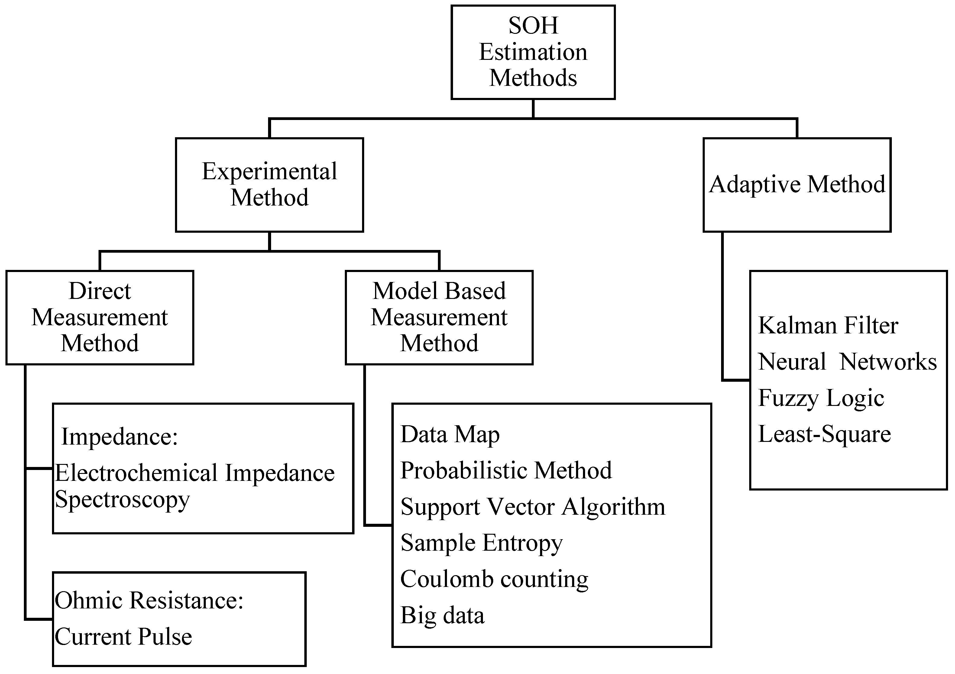
2.3. State of Health (SOH) of Battery

Venugopal et al. [5] assessed the way in which a usable battery’s capacity should not fall below 80% of its original capacity because of its exponential degradation below 80%. Estimating battery SOH is challenging, as many unknown and unpredictable aspects influence the battery’s health. To estimate the SOH of Li–ion batteries utilized in EV applications, an independently recurrent neural network (IndRNN)-based SOH estimation model was used.
A deep learning-based data-driven technique has been used to estimate SOH. Because of its ability to capture the complicated non-linear properties of batteries by avoiding the gradient problem and allowing the neural network to learn long-term relationships among capacity degradations, the IndRNN has been used [65,66]. Shi et al. [67] assert that, in a battery management system, an online state of health (SOH) estimate is critical for Li–ion batteries. Therefore, various measures linked to internal resistance have been offered as SOH estimate indicators. Figure 7 shows the flow chart of the state of health and its methods. The reduction of temperature disturbances and the elimination of state of charge (SOC) disturbances were considered. The suggested indicators and estimation approach were estimated with a maximum error of 2.301%, demonstrating its dependability and practicality. The most common method for calculating SOH is to use the battery capacity. However, capacity estimation in EVs is challenging to accomplish online. This work proposes measurable SOH indicators from ECM based on statistical analysis [45]. Xu et al. [68] described the battery parameters and used current, charge depth, and charge frequency to determine charge behavior and charge capacity. The K-means clustering technique was used to investigate various charging habits, and the findings demonstrate that there are clear distinctions between the various groups. The charge behavior characteristics, for which the charge current has the most impact on the state of the health of the battery, are connected to the attenuation rate of the vehicle’s lithium battery capacity. The frequency of charge is the second-most critical element impacting battery health, offering a theoretical framework for the investigation of alternative charge habits and excellent charge behavior suggestions [69,70].
Lin et al. [71] estimated SOH without utilizing the whole battery profile and concluded that incremental capacity analysis could increase estimation efficiency. A robust cubic smoothing spline approach to generate an incremental capacity curve was used. This approach is superior to traditional filters that need trial-and-error window size tweaking. The suggested technique estimated the SOH even without full charge or discharge data. Gabriel et al. [72] assert that, in the 0 to 50 °C range, the discharge capacity of LiCoO2 (LCO) batteries charged at one temperature and discharged at another should be investigated for low and high status of health (SOH) batteries. A discharge capacity dependency on relative charge–discharge temperatures was discovered. The surface self-temperature of the battery was tested at varied charging and discharging currents in 0.2 C to 2 C C-rates, with the surface heat being effectively constant with the charging C-rates. In the battery discharges, however, a considerable surface temperature rise is observed, which corresponds to the battery SOH dependency. The temperature at which LCO batteries are charged and discharged in the 0–50 °C range, as well as their SOH, affects their performance. When charging or discharging temperatures are loaded, the amount of charge stored or supplied also decreases, and this decline is particularly pronounced at 0 °C. At any temperature, the Coulombic efficiency of an L battery is always lower than that of an H battery. Diao et al. [73] have asserted that the current maximum available energy (MAE) to the rated total energy be proposed and defined as the energy SOH for a battery pack. In comparison with the capacity and power of SOH, this technique is more suitable for and accurate in reflecting the real status of the battery pack. The superiority of this strategy is demonstrated by comparison and study in several ways. The energy SOH model for a battery pack incorporates capacity and internal resistance inconsistencies. The data from LiCoO2 and LiFePO4 batteries are used to analyze the cases. This demonstrates that both deterioration and irregularity influence a battery pack’s SOHE [74,75].
Battery energy storage is a key enabling technology for electric vehicles and renewable energy sources, according to Moura et al. [76] SOH estimation of Li–ion can also be achieved using the least squares model, which combines an empirical degradation model and a data-driven method. Using parabolic PDEs and nonlinearly parameterized output functions, the state of health is estimated as a parameter to pinpoint the problem. The elements influencing a battery’s life degradation are depicted in Figure 8. The swapping identification strategy for unidentified parameters was applied to the diffusion partial differential equation (PDE). The availability of full-state measurements was a key premise of this investigation. By creating a signal-only parametric model, this assumption was relaxed. This made it possible to create an adaptive observer that estimates states (SOC) and parameters (SOH) at the same time. We also wish to investigate the theoretical and practical performance of the state estimator/parameter identifier structure. Cacciato et al. [77] asserted that, to permit the exact construction of the control algorithms for energy storage systems (ESS), detailed information on a battery pack’s SOC and SOH is required. A new method for estimating SOC and SOH was thus proposed. This is based on the creation of a battery circuit model as well as a technique for adjusting model parameters. Accurate ESS modelling is critical because it helps power electronics systems to improve their control strategies. In the field of primary electrochemical technologies, a unique approach for ESS state estimation has been devised. The core component of the technique is a PI-based observer system in which the SOC and SOH values are calculated via an appropriate algorithm. A study by Hatzell et al. [78] on Li–ion battery characterization, control, and optimization is reviewed in this work. It looks at the basic degrading mechanisms in cycled cells before highlighting the difficulties in managing them. This necessitated the determination of how batteries fail and the building of fundamental models of their failure that are control oriented. Impedance spectroscopy is a powerful method for identifying battery health models, as well as for online health estimation, prognostics, and diagnostics. Health-conscious battery control is a very interesting study subject, especially if the community can remove the limitations imposed by “conventional” battery control systems such as CCCV charging/discharging and rigorous cell-to-cell balance. Lipu et al. [7] observed that electric vehicles with Li–ion batteries have difficulty in predicting their health and useful remaining life. The SOH and RUL of a battery were analyzed using traditional procedures, model-based approaches, and algorithms. The construction of an adequate model for calculating SOC while taking into consideration different model disruptions and uncertainties must be investigated. A thermal management module should be implemented inside the BMS to decrease the impact of thermal runaway. Cuma et al. [79] assert that estimating methodologies help with battery management, vehicle energy management, and vehicle control by completing several duties. In order to estimate the capacities and instantaneous resistances—major indications of SOH—for lead–acid batteries, sample entropy (SE), subspace parameter (SP), equivalent circuit parameter (ECP) and other methods are proposed along with their percentage of error. To undertake the same for Li–ion batteries, genetic algorithm (GA), model-based, dynamic impedance, dynamic Bayesian network (DBN), and other methods are employed along with their accuracies. Qin et al. [6] propounded that, for an intelligent battery management system (BMS), state of health (SOH) prediction in Li–ion batteries is critical. The occurrence of capacity regeneration events, on the other hand, presents a significant barrier to the precise estimation of battery SOH. From the raw SOH time series of the present battery, the global deterioration of the nth trend and regeneration phenomena (defined by regeneration amplitude and regeneration cycle number) was derived. A current battery’s global deterioration trend and regeneration phenomena were prospected and then combined to produce overall SOH prediction values. A historical battery’s regeneration threshold was calculated using particle swarm optimization (PSO). The global deterioration trend was forecast using a Gaussian process (GP) model, while the regeneration amplitude and cycle number of each regeneration zone were forecast using linear models. Yeon Lee et al. [80] have stated that a Li-ion battery’s state of health (SOH) is crucial in deciding how long it will last. Before developing a suitable SOH estimation model, one must consider the factors that cause battery deterioration. Multiple regression models with selected parameters have been developed to account for the effects of deterioration. The reduction in battery capacity and increase in resistance are used as signs that the battery is getting older. Multiple regression analysis has been used to examine the complicated impacts of factors on Li–ion battery degeneration [81].
Anselma et al. [82] have explained that the fundamental problem in the design of hybrid electric cars is achieving a sufficient high-voltage battery lifespan while maintaining fuel efficiency. While there have been various control techniques that are sensitive to a battery’s state of health (SOH) for HEVs proposed in the literature, they have seldom been empirically verified. This work sought to demonstrate an optimum, multi-objective battery SOH-sensitive off-line HEV control strategy based on dynamic programming (DP), which had been empirically tested in terms of battery lifetime prediction capabilities. Cells with present characteristics were aged for three distinct expected lifespan instances in an experimental campaign. By incorporating the influence of temperature and updating the empirical ageing characterization curve, the battery ageing model’s predicted accuracy was increased [83,84]. Yang et al. [85] analyzed the existing characteristic parameters for defining battery SOH at the cell and pack levels. The factors used to define SOH, including capacity, impedance, and ageing-mechanism parameters, were utilized to categorize SOH estimating techniques. Limiting the SOH definition to battery capacity or impedance estimation makes it difficult to characterize a battery’s ageing status completely. An emphasis on pack-level SOH was also created in addition to a cell-level SOH definition. The capacity to distribute energy and cell-to-cell variances was taken into account when defining pack-level SOH, internal deterioration types, data accessibility, and the aims of chosen SOH-related characteristics. The current SOH prognosis approaches mostly consist of short-term state estimate and long-term RUL prediction, which judges battery retirement point and ignores the instructional value of the battery ageing process [86]. M Dalal et al. [87] have stated that a battery’s life could be estimated based on dynamic properties using a lumped parameter battery model, including non-linear open-circuit voltage, current, temperature, cycle number, and time-dependent storage capacity. The remaining usable life (RUL) of the system was estimated using statistical estimation methods with a particle filtering framework and a sequential significance resampling approach to estimate a battery’s EOL and EOD for individual discharge cycles and its lifecycle. Estimation can thus be undertaken with the help of developed methods (RUL) [88]. Sarikurt et al. [89] attempted to estimate the number of battery pulse widths in the ECE 15 driving cycle, with a new approach for obtaining the SOH of a battery using the cycle number also shown. An analytical SOH estimation approach is provided in their study wherein the available capacity of the battery depends on the number of cycles, i.e., the exploitable capacity of the battery decreases as the number of cycles increases [90].

2.4. Effect of Regenerative Braking on the Life of Battery

Keil and Jossen [75] have suggested that a high charging current using regenerative braking deteriorates battery life. Thus, they conducted a lifecycle study on a Li–ion battery by using different driving load profiles for different regenerative braking values.
Li–ion batteries were subjected to various regenerative braking situations at various temperatures and levels of charge (SOCs). Cells cycled at 25 °C are shown to offer a fair balance between calendar and cyclic ageing. Furthermore, on evaluating the battery ageing in EVs based on driving load profile, they revealed that calendar ageing diminishes as the temperature drops, and cycle ageing increases and becomes more sensitive to load profile changes. Cycling over 200,000 km demonstrated that regenerative braking extends battery life by reducing the cycle depth. Figure 9 shows the layout of the energy recovery due to integrated regenerative and neural network methods. This significantly reduces capacity fade and increases resistance. The evaluation of different levels of regenerative braking has shown that short-duration recharging times during braking do not enhance battery degradation for a typical driving load profile—even at low battery temperatures of 10 °C. Higher degrees of regenerative braking inhibit degradation, particularly at high SOC and low temperature, which are prime conditions for lithium plating. The lower degradation is due to the battery’s reduced DOD when partially refilled by using shorter recharging periods during braking moments [91]. The amount of charge refilled at the charging station appears to have a greater impact on capacity fade than the overall charge flow. As a result, EVs benefit from a high level of regenerative braking, but only when low recharging currents are used [92].
Jingying et al. [93] have revealed that regenerative braking increases the temperature of a Li–ion battery. They proposed a control method subjected to braking safety regulations and adjusted the regenerative braking ratio by using a fuzzy controller. It was found that, by modifying the charge current due to regenerative braking, the proposed control strategy suppresses the rise in battery temperature. It was also observed that, along with the real-time battery SOC and temperature, the fuzzy logic controller adjusts the regenerative braking ratio. Carrilero et al. [94] examined the above C/2 charging regimes. They determined that a cell’s overall performance is suitable for fast charging when more than 90% of its effective capacity can be recharged in 15 min or less throughout its life (more than 5000 cycles) without experiencing a significant loss in power capability.
The usable capacity of a battery is dependent on its cycle count, as shown in Figure 10. In the figure blue dots represent the experimental data and solid line is the curve fitted. the A battery’s useful capacity diminishes as its cycle count rises. In addition to extending HEV driving time by providing backup power in deceleration mode, Asif et al.’s RBS for HEVs also lengthened battery life cycles by charging ultracapacitors [95]. Without using a buck or boost system, the improved regenerative braking system has lower power losses between the BLDC motor and ESS. In RBS mode, energy is increased by using an induction motor in winding and the inverter’s H-bridge switching approach to transfer it to ESS with the fewest possible losses. Through a fuzzy logic controller, pulse width modulation (PWM) is used to operate these switches. As a result, battery life and working time will both increase. Wu et al. [96] presented a hierarchical control technique by considering battery ageing. The up-level controller’s control objectives were to increase energy recovery and decrease battery ageing while ensuring vehicle braking safety in emergency braking mode. The low-level controller, which takes instructions from the up-level controller (EM), manages the pneumatic braking system and the electric motor. Maximum EM torque and battery charging power have been defined for the protection of the EM and battery. The real-time calculation performance was assessed using controller-in-the-loop testing and the control efficacy of the suggested method. For both control strategies, the braking distance, vehicle speed, wheel speed, and slip ratio were nearly identical (with or without battery ageing consideration). When battery ageing was taken into account, the EM motor was reduced in size, considering EM torque. Long et al. [97] analyzed the hybrid power supply system made up of ultracapacitors and batteries that can increase an EV’s one-time charging driving mileage and energy recovery efficiency. A design technique for H∞ [27,28] was proposed based on stability and dynamic responsiveness. The experimental results show that a vehicle can gain 5.3% braking energy (approximately) when utilizing the suggested energy-management scheme and the recommended H∞ over the use of a regular PID controller under the same conditions. To protect the battery from damage incurred by excessive charging current during regenerative braking, Cao et al. [98] suggest a control strategy that uses the charging current as a control object. The weighted mixed-sensitivity issue was used to model the design of regenerative braking controllers.
To guarantee the robustness of the closed-loop system in the presence of uncertainties, such as parameter perturbation during the period and unidentified model dynamics, the H∞ robust controller for regenerative braking was created together with a DC–DC converter. This also minimizes the effect of the disturbance, battery voltage variation, state of the road, and driving profile of the vehicle. In terms of steady-state tracking error, response speed and energy recovery, the experimental results reveal that the H∞ robust controller outperforms the typical PI controller.
Zhu et al. [99] suggest a technique for regenerative braking management based on multi-objective optimization of switched reluctance generator (SRG) drive systems to increase braking effectiveness and regenerative energy in front-wheel drive electric vehicles (EVs) using switched reluctance motors (SRMs). Safety and braking energy were both taken into consideration when developing the partition brake force distribution method. The low speed and high-speed scenarios form the basis of the SRG propulsion system model. Mechanical braking system, SRG drive system model, and partition braking force distribution system are three types of braking system models for front-wheel drive vehicles with 4-phase 8/6 SRM. Regeneration braking was later offered as a control approach to increase braking effectiveness and vehicle regeneration energy, based on multi-objective optimization of SRG propulsion systems, including output, generated power, torque smoothness, and current smoothness as optimization targets selected to increase battery life, range, braking comfort, and maneuverability.
Naseri et al. [100] introduced a hybrid energy storage system, wherein complementary qualities of batteries and ultracapacitors may be efficiently employed (HESS). The usage of an HESS in electric cars (EVs) has several advantages, including quicker acceleration, more effective regenerative braking, and improved battery safety. An innovative RBS based on the utilization of HESS is suggested for EVs with BLDC motors. During regenerative braking and/or energy regeneration, the ultracapacitor utilizes the appropriate switching pattern of the inverter to store the vehicle’s kinetic energy. Power electronics interfaces are, therefore, no longer necessary. An MLP-ANN controller was used to control how much braking power is applied to the front and rear wheels of the EV. Furthermore, a PI controller was employed to control the PWM duty cycle. Dixon et al. [101] have stated that, through the interplay of the other aforementioned factors, such as the vehicle speed and the state of charge of the battery, the capacitor voltage is regulated by an insulated-gate bipolar transistor (IGBT) PWM technique used in the buck–boost converter. For an electric car, a simulated ultracapacitor bank was constructed. The purpose of this device is to allow the vehicle to accelerate and decelerate more quickly with less energy loss and main battery pack degradation. An IGBT buck–boost converter controlled the system by monitoring the battery voltage, SOC, automobile speed, instantaneous currents at both terminals (load and ultracapacitor), and the ultracapacitor’s actual voltage.
Carteret et al. [102] recommend hybridizing batteries and ultracapacitors to reduce peak battery currents. Extending the life of a battery has the potential to enhance total propulsion efficiency, increase range, and reduce life cycle costs. They constructed a programmable control strategy that can be altered to satisfy various objectives. When employed in a hybrid vehicle system, ultracapacitors may provide high burst power even when the battery capacity is low, due to the low SOC, allowing the vehicle to keep its acceleration performance. Ultracapacitors can be employed in an EV hybrid battery/ultracapacitor system. Extending the life of the battery can improve total propulsion efficiency, boost range, and lower life cycle costs.
A better solution for the recuperation of the energy lost during braking is regenerative braking. Every drive cycle or city driving involves a series of acceleration and braking. So, there is a lot of scope for energy saving using regenerative braking at the same time it also has ill effects on the battery. Figure 11 summarizes both the positive and negative aspects of regenerative braking. This review paper discussed various strategies of regenerative braking followed in HEVs and EVs and has also provided insights into the impact of regenerative braking on the battery life of EVs and HEVs. SOC and SOH are important factors for indicating battery life and its condition. Though various methods are available for estimating battery SOC and SOH, accurate prediction of its values is a challenge. Along with disadvantages, such as an increase in vehicle weight and complexity of the braking system, and the long-term effects of short charging on the battery, regenerative braking also offers advantages. From the outcomes of various research, it is very clear that regenerative braking has been shown to extend battery life by decreasing discharge depth. Further, regenerative braking increases operating range, reduces wear and tear of brake pads, and reduces emissions marginally.
On the other hand, the recuperation of energy recovered from the regenerative braking system depends upon the battery chemistry, battery operating temperature, vehicle architecture, driving conditions, and driving habits. Considering these factors, it becomes very complicated to design a regenerative system to recover the maximum energy from the system. Therefore, during maximum deceleration, a certain amount of energy should directly charge the battery (at a level that is safe for the battery), and the excess energy should be stored in an ultra- or supercapacitor. The combination of battery and supercapacitor is known as a hybrid energy storage system (HESS). The energy stored in an ultracapacitor or supercapacitor can be utilized for immediate acceleration after braking in traffic congestion situations. This will give better regeneration output from the systems without compromising battery life. Supercapacitors are more effective than the vehicle’s primary battery pack for regeneration because they can meet the demands of long cycle life and high-power density. Therefore, a supercapacitor can help the battery pack during times of peak power consumption, extending the battery life and enhancing vehicle acceleration.

3. Conclusions

Various regenerative braking techniques have been introduced to extract energy from the braking phenomenon. Two basic techniques have been implemented, i.e., the parallel hybrid braking system and the fully controllable hybrid braking system. The fully controllable hybrid braking system includes further sub-strategies such as optimal braking performance and optimal braking energy recovery, which are based on the braking distribution of the vehicle. Many authors have compared these strategies and testified to their advantages and disadvantages. Moreover, in EVs and hybrid vehicles, conventional regenerative braking is merged with ABS. Higher regenerative braking efficiency has also been achieved by downsizing the AMT, as more energy loss is observed at lower brake torque. The high speed of the rotor causes iron loss which reduces energy recovery efficiency due to regenerative braking. A combined H∞ controller has been implemented in RBSs, using fuzzy logic systems to provide optimal performance while considering the SOC of the battery. The H∞ controller has been further combined with PID and SMC to further improve the braking process.
In the field of SOC estimation, there has been much research into the use of model-based and data-driven estimating methods. In SOC estimation, both model-based and data-driven approaches have shown significant results. A model-based strategy is theoretically the best approach, but has high complexity compared with other methods. The conventional Coulomb counting method, occasionally corrected by EKF tracking with a pre-defined battery model, gives better results, as well as an adaptive nonlinear observer design that compensates for nonlinearity and achieves better estimation accuracy. SOH is related to battery ageing and various methods have been developed to estimate an accurate SOH. From that estimation, it can be determined when a battery should be replaced. In EVs, regenerating braking is used to improve battery life as a higher level of regeneration can reduce battery ageing.
It has been found that, if the temperature is too low or high, the battery life further deteriorates due to the current occurring due to the regenerative braking. It has been stated that 25 °C provides the optimal conditions to slow down battery ageing due to an RBS. It has also been found that the Li plating increases with higher SOC, higher charging currents for longer durations and low temperature. Therefore, at low temperatures, the ageing of the battery increases and becomes susceptible to changes in the load profile. A higher degree of regeneration braking ameliorates the battery life by reducing the battery’s DOD by using shorter and lower recharging currents. This also reduces battery life degradation even at high SOC and high temperature. Thus, only a high level of regenerative braking for low recharging currents is preferred for battery life. It has also been found that regenerative braking increases the internal resistance of the battery, which eventually increases the temperature of the Li–ion battery.
Many control strategies have been introduced in modern RBSs, including the use of a fuzzy logic controller. The fuzzy controller adjusts the regenerative braking ratio by observing real-time battery SOC and temperature to prevent the increase in battery temperature. The electric motor torque and battery charging power have also been taken into account in the hierarchical control while adjusting the regenerative braking ratio. To reduce the battery ageing rate, the size of the motor should be optimized. An H∞ controller also protects the battery from parameter perturbation and excessive charging current obtained during regenerative braking. SRG drive systems improve regenerative recovery energy while keeping the smoothness in the charging current and improving the battery lifetime. The ultracapacitors allow quick vehicle acceleration and deceleration with minimum energy loss while keeping the main battery safe. Ultracapacitors are used to reduce the peak current, which reduces battery life. Beyond this, ultracapacitors provide high burst power when a battery’s SOC is low.

4. Future Work

There has been little work undertaken to signify the effect of regenerative braking on the SOH of a battery. However, much work has been undertaken with regard to the incorporation of ultracapacitors in regenerative braking as they support the battery in storing charge for a longer time. Thus, this work can be further extended by analyzing the effect of supercapacitors on the storage of charge and, thereby, the charging of the battery.

Author Contributions

Conceptualization, methodology, writing—original draft preparation, R.K.C. and D.C.; resources, R.K.C., D.C., B.B., P.P.D., J.T., D.T. and T.S.; language editing T.S., D.T. and J.T.; supervision R.K.C.; formal analysis, R.K.C., D.C., B.B. and P.P.D.; writing—review and editing, R.K.C., B.B., P.P.D., J.T. and T.S. All authors have read and agreed to the published version of the manuscript.

Funding

This research received no external funding.

Data Availability Statement

Data available on request.

Conflicts of Interest

The auth ors declare that they have no known competing financial interest or personal relationships that could have appeared to influence the work reported in this paper.

References

  1. Yoong, M.K.; Gan, Y.H.; Gan, G.D.; Leong, C.K.; Phuan, Z.Y.; Cheah, B.K.; Chew, K.W. Studies of regenerative braking in electric vehicle. In Proceedings of the 2010 IEEE Conference on Sustainable Utilization and Development in Engineering and Technology, Kuala Lumpur, Malaysia, 20–21 November 2010; IEEE: Miami, FL, USA, 2010; pp. 40–45. [Google Scholar]
  2. Dixon, J.W.; Ortuzar, M.E. Ultracapacitors+ DC-DC converters in regenerative braking system. IEEE Aerosp. Electron. Syst. Mag. 2002, 17, 16–21. [Google Scholar] [CrossRef]
  3. Piller, S.; Perrin, M.; Jossen, A. Methods for state-of-charge determination and their applications. J. Power Source 2001, 96, 113–120. [Google Scholar] [CrossRef]
  4. Hu, C.; Youn, B.D.; Chung, J. A multiscale framework with extended Kalman filter for lithium-ion battery SOC and capacity estimation. Appl. Energy 2012, 92, 694–704. [Google Scholar] [CrossRef]
  5. Venugopal, P. State-of-Health estimation of li-ion batteries in electric vehicle using IndRNN under variable load condition. Energies 2019, 12, 4338. [Google Scholar] [CrossRef] [Green Version]
  6. Qin, T.; Zeng, S.; Guo, J.; Skaf, Z. State of health estimation of li-ion batteries with regeneration phenomena: A similar rest time-based prognostic framework. Symmetry 2016, 9, 4. [Google Scholar] [CrossRef] [Green Version]
  7. Lipu, M.H.; Hannan, M.A.; Hussain, A.; Hoque, M.M.; Ker, P.J.; Saad, M.M.; Ayob, A. A review of state of health and remaining useful life estimation methods for lithium-ion battery in electric vehicles: Challenges and recommendations. J. Clean. Prod. 2018, 205, 115–133. [Google Scholar] [CrossRef]
  8. Cikanek, S.R.; Bailey, K.E. Regenerative braking system for a hybrid electric vehicle. In Proceedings of the 2002 American Control Conference (IEEE Cat. No. CH37301), Anchorage, AK, USA, 8–10 May 2002; IEEE: Miami, FL, USA, 2010; Volume 4, pp. 3129–3134. [Google Scholar]
  9. Panagiotidis, M.; Delagrammatikas, G.; Assanis, D. Development and Use of a Regenerative Braking Model for a Parallel Hybrid Electric Vehicle; SAE Transactions: Warrendale, PA, USA, 2000; pp. 1180–1191. [Google Scholar]
  10. Gao, Y.; Chen, L.; Ehsani, M. Investigation of the Effectiveness of Regenerative Braking for EV and HEV; SAE Transactions: Warrendale, PA, USA, 1999; pp. 3184–3190. [Google Scholar]
  11. Gao, Y.; Chu, L.; Ehsani, M. Design and control principles of hybrid braking system for EV, HEV and FCV. In Proceedings of the 2007 IEEE Vehicle Power and Propulsion Conference, Arlington, TX, USA, 9–12 September 2007; IEEE: Miami, FL, USA, 2007; pp. 384–391. [Google Scholar]
  12. Cacciatori, E.; Bonnet, B.; Vaughan, N.D.; Burke, M.; Price, D.; Wejrzanowski, K. Regenerative braking strategies for a parallel hybrid powertrain with torque controlled IVT. SAE Tech. Pap. 2005, 1, 3826. [Google Scholar]
  13. Gao, Y.; Ehsani, M. Electronic Braking System of EV And HEV-Integration of Regenerative Braking, Automatic Braking Force Control and ABS; SAE Transactions: Warrendale, PA, USA, 2001; pp. 576–582. [Google Scholar]
  14. Tur, O.; Ustun, O.; Tuncay, R.N. An introduction to regenerative braking of electric vehicles as anti-lock braking system. In Proceedings of the 2007 IEEE Intelligent Vehicles Symposium, Istanbul, Turkey, 13–15 June 2007; IEEE: Miami, FL, USA, 2007; pp. 944–948. [Google Scholar]
  15. Guo, J.; Wang, J.; Cao, B. Regenerative braking strategy for electric vehicles. In Proceedings of the 2009 IEEE Intelligent Vehicles Symposium, Xi’an, China, 3–5 June 2009; IEEE: Miami, FL, USA, 2009; pp. 864–868. [Google Scholar]
  16. Yeo, H.; Hwang, S.; Kim, H. Regenerative braking algorithm for a hybrid electric vehicle with CVT ratio control. Proc. Inst. Mech. Eng. Part D J. Automob. Eng. 2006, 220, 1589–1600. [Google Scholar] [CrossRef]
  17. Qiu, C.; Wang, G.; Meng, M.; Shen, Y. A novel control strategy of regenerative braking system for electric vehicles under safety critical driving situations. Energy 2018, 149, 329–340. [Google Scholar] [CrossRef]
  18. Nian, X.; Peng, F.; Zhang, H. Regenerative braking system of electric vehicle driven by brushless DC motor. IEEE Trans. Ind. Electron. 2014, 61, 5798–5808. [Google Scholar] [CrossRef]
  19. Chuanwei, Z. Experimental Research on H∞ Control for Regenerative Braking of Electric Vehicle. In Proceedings of the 2010 International Conference on Electrical and Control Engineering, Wuhan, China, 25–27 June 2010; IEEE: Miami, FL, USA, 2010; pp. 940–943. [Google Scholar]
  20. Ye, M.; Bai, Z.; Cao, B. Robust sliding model control for regenerative braking of electric vehicle. In Proceedings of the 2006 CES/IEEE 5th International Power Electronics and Motion Control Conference, Shanghai, China, 14–16 August 2006; IEEE: Miami, FL, USA, 2006; Volume 3, pp. 1–4. [Google Scholar]
  21. Cao, J.; Cao, B.; Xu, P.; Bai, Z. Regenerative-braking sliding mode control of electric vehicle based on neural network identification. In Proceedings of the 2008 IEEE/ASME International Conference on Advanced Intelligent Mechatronics, Xi’an, China, 2–5 July 2008; IEEE: Miami, FL, USA, 2008; pp. 1219–1224. [Google Scholar]
  22. Cao, J.; Cao, B.; Chen, W.; Xu, P. Neural network self-adaptive PID control for driving and regenerative braking of electric vehicle. In Proceedings of the 2007 IEEE International Conference on Automation and Logistics, Shandong, China, 18–21 August 2007; IEEE: Miami, FL, USA, 2007; pp. 2029–2034. [Google Scholar]
  23. Gao, H.; Gao, Y.; Ehsani, M. A neural network based SRM drive control strategy for regenerative braking in EV and HEV. In Proceedings of the IEMDC 2001. IEEE International Electric Machines and Drives Conference (Cat. No. 01EX485), Cambridge, MA, USA, 17–20 June 2001; IEEE: Miami, FL, USA, 2001; pp. 571–575. [Google Scholar]
  24. Xu, G.; Li, W.; Xu, K.; Song, Z. An intelligent regenerative braking strategy for electric vehicles. Energies. 2011, 4, 1461–1477. [Google Scholar] [CrossRef] [Green Version]
  25. Li, X.; Xu, L.; Hua, J.; Li, J.; Ouyang, M. Regenerative braking control strategy for fuel cell hybrid vehicles using fuzzy logic. In Proceedings of the 2008 International Conference on Electrical Machines and Systems, Wuhan, China, 17–20 October 2008; IEEE: Miami, FL, USA, 2010; pp. 2712–2716. [Google Scholar]
  26. Zhang, J.M.; Song, B.Y.; Cui, S.M.; Ren, D.B. Fuzzy logic approach to regenerative braking system. In Proceedings of the 2009 International Conference on Intelligent Human-Machine Systems and Cybernetics, Hangzhou, China, 26–27 August 2009; IEEE: Miami, FL, USA, 2009; Volume 1, pp. 451–454. [Google Scholar]
  27. Peng, D.; Zhang, Y.; Yin, C.L.; Zhang, J.W. Combined control of a regenerative braking and antilock braking system for hybrid electric vehicles. Int. J. Automot. Technol. 2008, 9, 749–757. [Google Scholar] [CrossRef]
  28. Paul, D.; Velenis, E.; Cao, D.; Dobo, T. Optimal μ-Estimation-Based regenerative braking strategy for an AWD HEV. IEEE Trans. Transp. Electrif. 2016, 3, 249–258. [Google Scholar] [CrossRef]
  29. Zhang, J.; Lv, C.; Gou, J.; Kong, D. Cooperative control of regenerative braking and hydraulic braking of an electrified passenger car. Proc. Inst. Mech. Eng. Part D J. Automob. Eng. 2012, 226, 1289–1302. [Google Scholar] [CrossRef]
  30. Ahn, J.K.; Jung, K.H.; Kim, D.H.; Jin, H.B.; Kim, H.S.; Hwang, S.H. Analysis of a regenerative braking system for hybrid electric vehicles using an electro-mechanical brake. Int. J. Automot. Technol. 2009, 10, 229–234. [Google Scholar] [CrossRef]
  31. Li, L.; Wang, X.; Xiong, R.; He, K.; Li, X. AMT downshifting strategy design of HEV during regenerative braking process for energy conservation. Appl. Energy 2016, 183, 914–925. [Google Scholar] [CrossRef]
  32. Junzhi, Z.; Yutong, L.; Chen, L.; Ye, Y. New regenerative braking control strategy for rear-driven electrified minivans. Energy Convers. Manag. 2014, 82, 135–145. [Google Scholar] [CrossRef]
  33. Bailey, K.E.; Powell, B.K.; Villec, G.N. ABS/traction assist/regenerative braking application of hardware-in-the-loop. In Proceedings of the 1998 American Control Conference. ACC (IEEE Cat. No. 98CH36207), Philadelphia, PA, USA, 26 June 1998; IEEE: Miami, FL, USA, 1998; Volume 1, pp. 503–507. [Google Scholar]
  34. Ko, J.; Ko, S.; Son, H.; Yoo, B.; Cheon, J.; Kim, H. Development of brake system and regenerative braking cooperative control algorithm for automatic-transmission-based hybrid electric vehicles. IEEE Trans. Veh. Technol. 2014, 64, 431–440. [Google Scholar] [CrossRef]
  35. Lv, C.; Zhang, J.; Li, Y.; Yuan, Y. Mechanism analysis and evaluation methodology of regenerative braking contribution to energy efficiency improvement of electrified vehicles. Energy Convers. Manag. 2015, 92, 469–482. [Google Scholar] [CrossRef]
  36. Qiu, C.; Wang, G. New evaluation methodology of regenerative braking contribution to energy efficiency improvement of electric vehicles. Energy Convers. Manag. 2016, 119, 389–398. [Google Scholar] [CrossRef]
  37. Baccouche, I.; Jemmali, S.; Mlayah, A.; Manai, B.; Amara, N.E. Implementation of an improved Coulomb-counting algorithm based on a piecewise SOC-OCV relationship for SOC estimation of li-IonBattery. arXiv 2018, arXiv:1803.10654. [Google Scholar]
  38. Sauer, D.U.; Bopp, G.; Jossen, A.; Garche, J.; Rothert, M.; Wollny, M. State of Charge—What do we really speak about. In Proceedings of the 21st International Telecommunications Energy Conference, Kopenhagen, Denmark, 9 June 1999; pp. 6–9. [Google Scholar]
  39. Chiasson, J.; Vairamohan, B. Estimating the state of charge of a battery. In Proceedings of the 2003 American Control Conference, Denver, CO, USA, 4–6 June 2003; IEEE: Miami, FL, USA, 2003; Volume 4, pp. 2863–2868. [Google Scholar]
  40. Jia, C.; Zhou, J.; He, H.; Li, J.; Wei, Z.; Li, K.; Shi, M. A novel energy management strategy for hybrid electric bus with fuel cell health and battery thermal-and health-constrained awareness. Energy 2023, 271, 127105. [Google Scholar] [CrossRef]
  41. Zhang, R.; Xia, B.; Li, B.; Cao, L.; Lai, Y.; Zheng, W.; Wang, H.; Wang, W. State of the art of lithium-ion battery SOC estimation for electrical vehicles. Energies 2018, 11, 1820. [Google Scholar] [CrossRef] [Green Version]
  42. Hannan, M.A.; Lipu, M.H.; Hussain, A.; Mohamed, A. A review of lithium-ion battery state of charge estimation and management system in electric vehicle applications: Challenges and recommendations. Renew. Sustain. Energy Rev. 2017, 78, 834–854. [Google Scholar] [CrossRef]
  43. Yanhui, Z.; Wenji, S.; Shili, L.; Jie, L.; Ziping, F. A critical review on state of charge of batteries. J. Renew. Sustain. Energy 2013, 5, 021403. [Google Scholar] [CrossRef]
  44. Ng, K.S.; Moo, C.S.; Chen, Y.P.; Hsieh, Y.C. State-of-charge estimation for lead-acid batteries based on dynamic open-circuit voltage. In Proceedings of the 2008 IEEE 2nd International Power and Energy Conference, Johor Bahru, Malaysia, 1–3 December 2008; IEEE: Miami, FL, USA, 2008; pp. 972–976. [Google Scholar]
  45. Berecibar, M.; Gandiaga, I.; Villarreal, I.; Omar, N.; Van Mierlo, J.; Van den Bossche, P. Critical review of state of health estimation methods of Li-ion batteries for real applications. Renew. Sustain. Energy Rev. 2016, 56, 572–587. [Google Scholar] [CrossRef]
  46. Zhang, J.; Xia, C. State-of-charge estimation of valve regulated lead acid battery based on multi-state Unscented Kalman Filter. Int. J. Electr. Power Energy Syst. 2011, 33, 472–476. [Google Scholar] [CrossRef]
  47. Anbuky, A.H.; Pascoe, P.E. VRLA battery state-of-charge estimation in telecommunication power systems. IEEE Trans. Ind. Electron. 2000, 47, 565–573. [Google Scholar] [CrossRef]
  48. Ran, L.; Junfeng, W.; Haiying, W.; Gechen, L. Prediction of state of charge of lithium-ion rechargeable battery with electrochemical impedance spectroscopy theory. In Proceedings of the 2010 5th IEEE Conference on Industrial Electronics and Applications, Taichung, Taiwan, 15–17 June 2010; IEEE: Miami, FL, USA, 2010; pp. 684–688. [Google Scholar]
  49. Huet, F. A review of impedance measurements for determination of the state-of-charge or state-of-health of secondary batteries. J. Power Source 1998, 70, 59–69. [Google Scholar] [CrossRef]
  50. Kim, J.; Cho, B.H. State-of-charge estimation and state-of-health prediction of a Li-ion degraded battery based on an EKF combined with a per-unit system. IEEE Trans. Veh. Technol. 2011, 60, 4249–4260. [Google Scholar] [CrossRef]
  51. Xie, J.; Ma, J.; Bai, K. Enhanced coulomb counting method for state-of-charge estimation of lithium-ion batteries based on peukert’s law and coulombic efficiency. J. Power Electron. 2018, 18, 910–922. [Google Scholar]
  52. Lee, S.; Kim, J.; Lee, J.; Cho, B.H. State-of-charge and capacity estimation of lithium-ion battery using a new open-circuit voltage versus state-of-charge. J. Power Source 2008, 185, 1367–1373. [Google Scholar] [CrossRef]
  53. Baccouche, I.; Mlayah, A.; Jemmali, S.; Manai, B.; Amara, N.E. $ Implementation of a Coulomb counting algorithm for SOC estimation of Li-Ion battery for multimedia applications. In Proceedings of the 2015 IEEE 12th International Multi-Conference on Systems, Signals & Devices (SSD15), Mahdia, Tunisia, 16–19 March 2015; IEEE: Miami, FL, USA, 2015; pp. 1–6. [Google Scholar]
  54. Jeong, Y.M.; Cho, Y.K.; Ahn, J.H.; Ryu, S.H.; Lee, B.K. Enhanced Coulomb counting method with adaptive SOC reset time for estimating OCV. In Proceedings of the 2014 IEEE Energy Conversion Congress and Exposition (ECCE), Pittsburgh, PA, USA, 14–18 September 2014; IEEE: Miami, FL, USA, 2014; pp. 1313–1318. [Google Scholar]
  55. How, D.N.; Hannan, M.A.; Lipu, M.H.; Ker, P.J. State of charge estimation for lithium-ion batteries using model-based and data-driven methods: A review. IEEE Access 2019, 7, 136116–136136. [Google Scholar] [CrossRef]
  56. Plett, G.L. Kalman-filter SOC estimation for LiPB HEV cells. In Proceedings of the 19th International Battery, Hybrid and Fuel Cell Electric Vehicle Symposium & Exhibition (EVS19), Busan, Republic of Korea, 19–21 October 2002; pp. 527–538. [Google Scholar]
  57. Sepasi, S.; Ghorbani, R.; Liaw, B.Y. Improved extended Kalman filter for state of charge estimation of battery pack. J. Power Source 2014, 255, 368–376. [Google Scholar] [CrossRef]
  58. Peng, S.; Chen, C.; Shi, H.; Yao, Z. State of charge estimation of battery energy storage systems based on adaptive unscented Kalman filter with a noise statistics estimator. IEEE Access 2017, 5, 13202–13212. [Google Scholar] [CrossRef]
  59. Liu, L.; Chen, Z.; Wang, C.; Lin, F.; Wang, H. Integrated system identification and state-of-charge estimation of battery systems. IEEE Trans. Energy Convers. 2012, 28, 12–23. [Google Scholar] [CrossRef]
  60. Kim, M.J.; Chae, S.H.; Moon, Y.K. Adaptive Battery State-of-Charge Estimation Method for Electric Vehicle Battery Management System. In Proceedings of the 2020 International SoC Design Conference (ISOCC), Yeosu, Republic of Korea, 21–24 October 2020; IEEE: Miami, FL, USA, 2020; pp. 288–289. [Google Scholar]
  61. El Din, M.S.; Hussein, A.A.; Abdel-Hafez, M.F. Improved battery SOC estimation accuracy using a modified UKF with an adaptive cell model under real EV operating conditions. IEEE Trans. Transp. Electrif. 2018, 4, 408–417. [Google Scholar] [CrossRef]
  62. He, Z.; Yang, Z.; Cui, X.; Li, E. A method of state-of-charge estimation for EV power lithium-ion battery using a novel adaptive extended Kalman filter. IEEE Trans. Veh. Technol. 2020, 69, 14618–14630. [Google Scholar] [CrossRef]
  63. Wang, J.; Cao, B.; Chen, Q.; Wang, F. Combined state of charge estimator for electric vehicle battery pack. Control. Eng. Pract. 2007, 15, 1569–1576. [Google Scholar] [CrossRef]
  64. Sun, F.; Hu, X.; Zou, Y.; Li, S. Adaptive unscented Kalman filtering for state of charge estimation of a lithium-ion battery for electric vehicles. Energy 2011, 36, 3531–3540. [Google Scholar] [CrossRef]
  65. Yang, D.; Wang, Y.; Pan, R.; Chen, R.; Chen, Z. A neural network-based state-of-health estimation of lithium-ion battery in electric vehicles. Energy Procedia 2017, 105, 2059–2064. [Google Scholar] [CrossRef]
  66. Lin, H.T.; Liang, T.J.; Chen, S.M. Estimation of battery state of health using probabilistic neural network. IEEE Trans. Ind. Inform. 2012, 9, 679–685. [Google Scholar] [CrossRef]
  67. Shi, G.; Chen, S.; Yuan, H.; You, H.; Wang, X.; Dai, H.; Wei, X. Determination of optimal indicators based on statistical analysis for the state of health estimation of a Lithium-ion battery. Front. Energy Res. 2021, 9, 262. [Google Scholar] [CrossRef]
  68. Xu, Z.; Yan, X.; Huang, B.; Wang, Y.; Dong, D.; Liu, Z. The Effect of Charge Behavior on Lithium Battery SOH. In Proceedings of the 2020 3rd International Conference on Advanced Electronic Materials, Computers and Software Engineering (AEMCSE), Shenzhen, China, 6–8 March 2020; IEEE: Miami, FL, USA, 2020; pp. 658–661. [Google Scholar]
  69. Kim, T.; Qiao, W.; Qu, L. Online SOC and SOH estimation for multicell lithium-ion batteries based on an adaptive hybrid battery model and sliding-mode observer. In Proceedings of the 2013 IEEE Energy Conversion Congress and Exposition, Denver, CO, USA, 15–19 September 2013; IEEE: Miami, FL, USA, 2013; pp. 292–298. [Google Scholar]
  70. Dong, G.; Han, W.; Wang, Y. Dynamic Bayesian Network-Based Lithium-Ion Battery Health Prognosis for Electric Vehicles. IEEE Trans. Ind. Electron. 2020, 68, 10949–10958. [Google Scholar] [CrossRef]
  71. Lin, C.P.; Cabrera, J.; Denis, Y.W.; Yang, F.; Tsui, K.L. SOH estimation and SOC recalibration of lithium-ion battery with incremental capacity analysis & cubic smoothing spline. J. Electrochem. Soc. 2020, 167, 090537. [Google Scholar]
  72. Mater, I.J. Effect of ambient temperature, C-rate and SOH on the charge and discharge performance and self-temperature of LCO batteries. Int. J. Electroactive Mater. 2021, 9, 1. [Google Scholar]
  73. Diao, W.; Jiang, J.; Zhang, C.; Liang, H.; Pecht, M. Energy state of health estimation for battery packs based on the degradation and inconsistency. Energy Procedia 2017, 142, 3578–3583. [Google Scholar] [CrossRef]
  74. Torai, S.; Nakagomi, M.; Yoshitake, S.; Yamaguchi, S.; Oyama, N. State-of-health estimation of LiFePO4/graphite batteries based on a model using differential capacity. J. Power Source 2016, 306, 62–69. [Google Scholar] [CrossRef]
  75. Balagopal, B.; Chow, M.Y. The state of the art approaches to estimate the state of health (SOH) and state of function (SOF) of lithium Ion batteries. In Proceedings of the 2015 IEEE 13th International Conference on Industrial Informatics (INDIN), Cambridge, UK, 22–24 July 2015; IEEE: Miami, FL, USA, 2015; pp. 1302–1307. [Google Scholar]
  76. Moura, S.J.; Chaturvedi, N.A.; Krstić, M. PDE estimation techniques for advanced battery management systems-Part II: SOH identification. In Proceedings of the 2012 American Control Conference (ACC), Montreal, QC, Canada, 27–29 June 2012; IEEE: Miami, FL, USA, 2012; pp. 566–571. [Google Scholar]
  77. Cacciato, M.; Nobile, G.; Scarcella, G.; Scelba, G. Real-time model-based estimation of SOC and SOH for energy storage systems. IEEE Trans. Power Electron. 2016, 32, 794–803. [Google Scholar] [CrossRef]
  78. Hatzell, K.B.; Sharma, A.; Fathy, H.K. A survey of long-term health modeling, estimation, and control of lithium-ion batteries: Challenges and opportunities. In Proceedings of the 2012 American Control Conference (ACC), Montreal, QC, Canada, 27–29 June 2012; IEEE: Miami, FL, USA, 2012; pp. 584–591. [Google Scholar]
  79. Cuma, M.U.; Koroglu, T. A comprehensive review on estimation strategies used in hybrid and battery electric vehicles. Renew. Sustain. Energy Rev. 2015, 42, 517–531. [Google Scholar] [CrossRef]
  80. Lee, P.Y.; Kim, J. Impact analysis of deterioration and SOH estimation based on multiple regression analysis. In Proceedings of the 2019 IEEE Transportation Electrification Conference and Expo, Asia-Pacific (ITEC Asia-Pacific), Jeju, Republic of Korea, 8–10 May 2019; IEEE: Miami, FL, USA, 2019; pp. 1–6. [Google Scholar]
  81. Fang, L.; Li, J.; Peng, B. Online Estimation and Error Analysis of both SOC and SOH of Lithium-ion Battery based on DEKF Method. Energy Procedia 2019, 158, 3008–3013. [Google Scholar] [CrossRef]
  82. Anselma, P.G.; Kollmeyer, P.; Lempert, J.; Zhao, Z.; Belingardi, G.; Emadi, A. Battery state-of-health sensitive energy management of hybrid electric vehicles: Lifetime prediction and ageing experimental validation. Appl. Energy 2021, 285, 116440. [Google Scholar] [CrossRef]
  83. Bloom, I.; Cole, B.W.; Sohn, J.J.; Jones, S.A.; Polzin, E.G.; Battaglia, V.S.; Henriksen, G.L.; Motloch, C.; Richardson, R.; Unkelhaeuser, T.; et al. An accelerated calendar and cycle life study of Li-ion cells. J. Power Source 2001, 101, 238–247. [Google Scholar] [CrossRef]
  84. Anselma, P.G.; Kollmeyer, P.; Belingardi, G.; Emadi, A. Multi-objective hybrid electric vehicle control for maximizing fuel economy and battery lifetime. In Proceedings of the 2020 IEEE Transportation Electrification Conference & Expo (ITEC), Detroit, MI, USA, 21–23 June 2020; IEEE: Miami, FL, USA, 2020; pp. 1–6. [Google Scholar]
  85. Yang, S.; Zhang, C.; Jiang, J.; Zhang, W.; Zhang, L.; Wang, Y. Review on state-of-health of lithium-ion batteries: Characterizations, estimations and applications. J. Clean. Prod. 2021, 314, 128015. [Google Scholar] [CrossRef]
  86. Wang, L.; Pan, C.; Liu, L.; Cheng, Y.; Zhao, X. On-board state of health estimation of LiFePO4 battery pack through differential voltage analysis. Appl. Energy 2016, 168, 465–472. [Google Scholar] [CrossRef]
  87. Dalal, M.; Ma, J.; He, D. Lithium-ion battery life prognostic health management system using particle filtering framework. Proc. Inst. Mech. Eng. Part O: J. Risk Reliab. 2011, 225, 81–90. [Google Scholar] [CrossRef]
  88. Saha, B.; Goebel, K. Modeling Li-ion battery capacity depletion in a particle filtering framework. In Proceedings of the Annual Conference of the PHM Society, San Diego, CA, USA, 29 November–2 December; 2021; Volume 1. Available online: http://www.papers.phmsociety.org/index.php/phmconf/article/view/1614 (accessed on 5 July 2023).
  89. Sarıkurt, T.; Ceylan, M.; Balikçi, A. An analytical battery state of health estimation method. In Proceedings of the 2014 IEEE 23rd International Symposium on Industrial Electronics (ISIE), Istanbul, Turkey, 1–4 June 2014; IEEE: Miami, FL, USA, 2014; pp. 1605–1609. [Google Scholar]
  90. Goebel, K.; Saha, B.; Saxena, A.; Celaya, J.R.; Christophersen, J.P. Prognostics in battery health management. IEEE Instrum. Meas. Mag. 2008, 11, 33–40. [Google Scholar] [CrossRef]
  91. Keil, P.; Jossen, A. Aging of lithium-ion batteries in electric vehicles: Impact of regenerative braking. World Electr. Veh. J. 2015, 7, 41–51. [Google Scholar] [CrossRef] [Green Version]
  92. Keil, P.; Jossen, A. Impact of dynamic driving loads and regenerative braking on the aging of lithium-ion batteries in electric vehicles. J. Electrochem. Soc. 2017, 164, A3081. [Google Scholar] [CrossRef]
  93. Huang, J.; Qin, D.; Peng, Z. Effect of energy-regenerative braking on electric vehicle battery thermal management and control method based on simulation investigation. Energy Convers. Manag. 2015, 105, 1157–1165. [Google Scholar] [CrossRef]
  94. Carrilero, I.; Ansean, D.; Viera, J.C.; Fernandez, Y.; Pereirinha, P.G.; González, M. Impact of fast-charging and regenerative braking in LiFePO4 batteries for electric bus applications. In Proceedings of the 2017 IEEE Vehicle Power and Propulsion Conference (VPPC), Belfort, France, 11–14 December 2017; IEEE: Miami, FL, USA, 2017; pp. 1–6. [Google Scholar]
  95. Asif, R.M.; Yousaf, A.; Rehman, A.U.; Shabbir, N.; Sadiq, M.T. Increase battery time by improvement in regenerative braking with storage system in hybrid vehicle. J. Appl. Emerg. Sci. 2019, 9, 53. [Google Scholar] [CrossRef]
  96. Wu, J.; Wang, X.; Li, L.; Du, Y. Hierarchical control strategy with battery aging consideration for hybrid electric vehicle regenerative braking control. Energy 2018, 145, 301–312. [Google Scholar] [CrossRef]
  97. Long, B.; Lim, S.T.; Bai, Z.F.; Ryu, J.H.; Chong, K.T. Energy management and control of electric vehicles, using hybrid power source in regenerative braking operation. Energies 2014, 7, 4300–4315. [Google Scholar] [CrossRef] [Green Version]
  98. Cao, B.; Bai, Z.; Zhang, W. Research on control for regenerative braking of electric vehicle. In Proceedings of the IEEE International Conference on Vehicular Electronics and Safety, Xi’an, China, 14–16 October 2005; IEEE: Miami, FL, USA, 2005; pp. 92–97. [Google Scholar]
  99. Zhu, Y.; Wu, H.; Zhang, J. Regenerative braking control strategy for electric vehicles based on optimization of switched reluctance generator drive system. IEEE Access 2020, 8, 76671–76682. [Google Scholar] [CrossRef]
  100. Naseri, F.; Farjah, E.; Ghanbari, T. An efficient regenerative braking system based on battery/ultracapacitor for electric, hybrid, and plug-in hybrid electric vehicles with BLDC motor. IEEE Trans. Veh. Technol. 2016, 66, 3724–3738. [Google Scholar]
  101. Dixon, J.W.; Ortúzar, M.; Wiechmann, E. Regenerative braking for an electric vehicle using ultracapacitors and a buck-boost converter. In Proceedings of the 17th Electric Vehicle Symposium (EVS17), (Canada), Detroit, MI, USA, 18–19 January 2019. [Google Scholar]
  102. Carter, R.; Cruden, A.; Hall, P.J. Optimizing for efficiency or battery life in a battery/ultracapacitor electric vehicle. IEEE Trans. Veh. Technol. 2012, 61, 1526–1533. [Google Scholar] [CrossRef]
Figure 1. Conceptual diagram of regenerative braking.
Energies 16 05303 g001
Figure 2. The layout of the paper.
Energies 16 05303 g002
Figure 3. Regenerative braking methods.
Energies 16 05303 g003
Figure 4. Parallel regeneration braking.
Energies 16 05303 g004
Figure 5. Series regeneration braking.
Energies 16 05303 g005
Figure 6. State of charge.
Energies 16 05303 g006
Figure 7. Flow chart of SOH estimation methods.
Energies 16 05303 g007
Figure 8. Degradation of battery life.
Energies 16 05303 g008
Figure 9. Flow chart of combined energy recovery of regeneration [11,16,17,19,21,22,26,29,31,36].
Energies 16 05303 g009
Figure 10. Relative capacity versus cycle number curve of a Kokam SLBP5520510H battery [95].
Energies 16 05303 g010
Figure 11. Flow chart showing the effects of regenerative braking on the life of a battery [2,91,92,93,95,96,97,99,100,102].
Energies 16 05303 g011
Disclaimer/Publisher’s Note: The statements, opinions and data contained in all publications are solely those of the individual author(s) and contributor(s) and not of MDPI and/or the editor(s). MDPI and/or the editor(s) disclaim responsibility for any injury to people or property resulting from any ideas, methods, instructions or products referred to in the content.

