
Decoupled Speed and Flux Control of a Three-Phase Permanent Magnet Synchronous Motor under an Open-Circuit Fault Using a PR Current Controller

Abstract
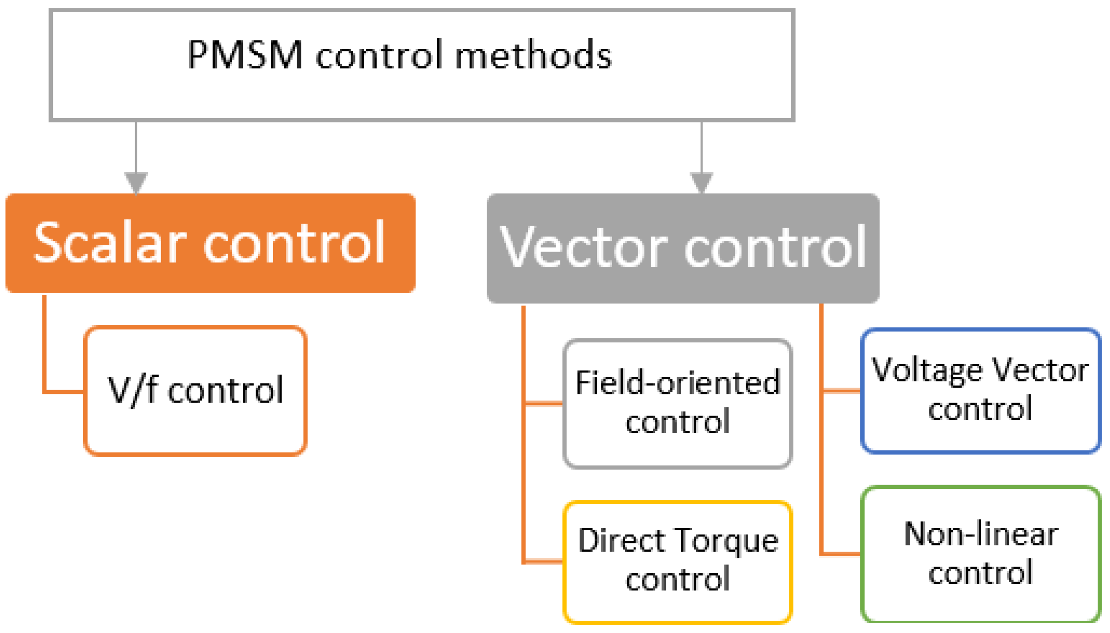
:1. Introduction
- Guarantee the continuous operation of the motor and enhance the reliability of the drive system against the open-circuit fault.
- Strong robustness control under flux change, speed change, and load conditions under OCF operation.
- Independent control of flux and speed is achieved during OCF conditions.
- Simple control method, no speed/position estimators are required, no PLL is required, and no need to design flux/torque observers.
2. Mathematical Model
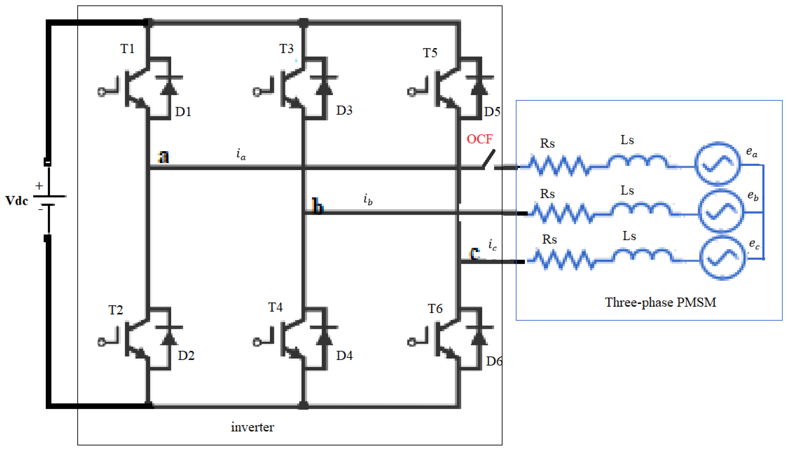
3. Open-Circuit Fault of PMSM
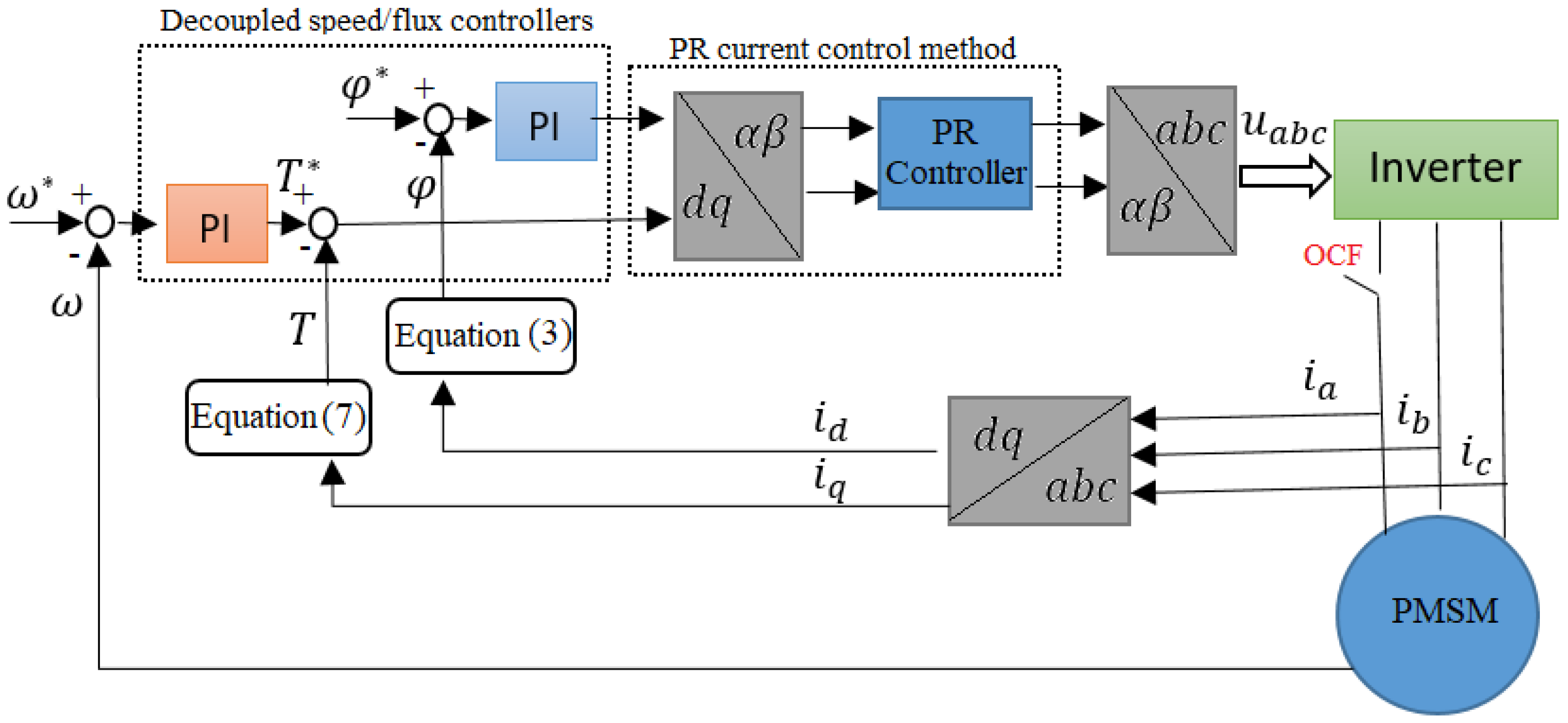
4. Proposed Control Method
4.1. Speed/Flux Control Design
4.2. PR Current Controller Design
- Initially, is set to zero.
- Gradually, is increased until stable oscillation occurs in the error waveform and this happened at .
- Then, .
- is adjusted until zero steady-state error is achieved.
- Choosing depends on the desired overshoot and settling time. A higher value of can decrease both the settling time and steady-state error; however, it can also result in increased overshoot. Therefore, selecting appropriate gains involves finding a balance between minimizing steady-state error and controlling overshoot.
5. Evaluation and Validation
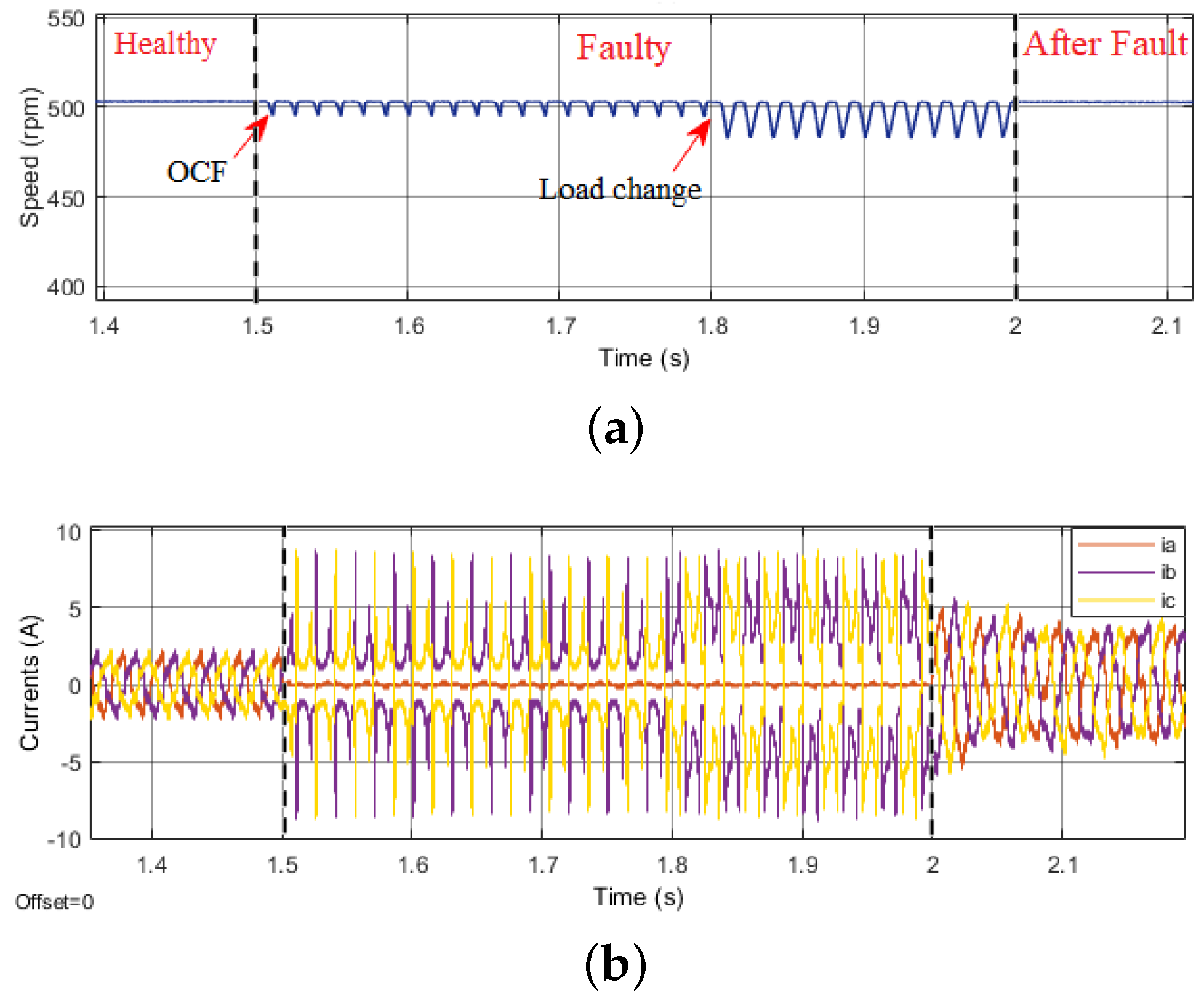
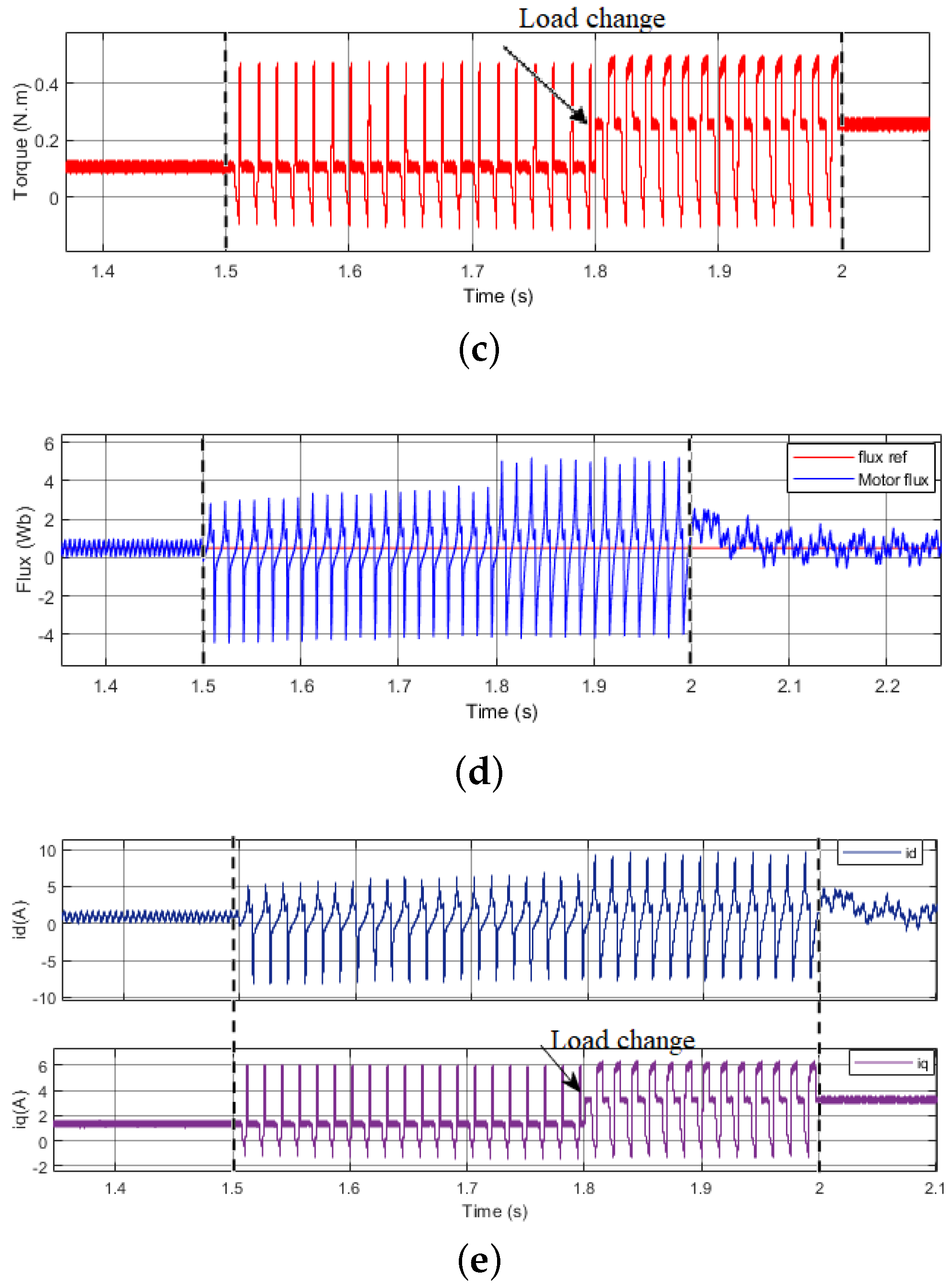
5.1. Simulation Results
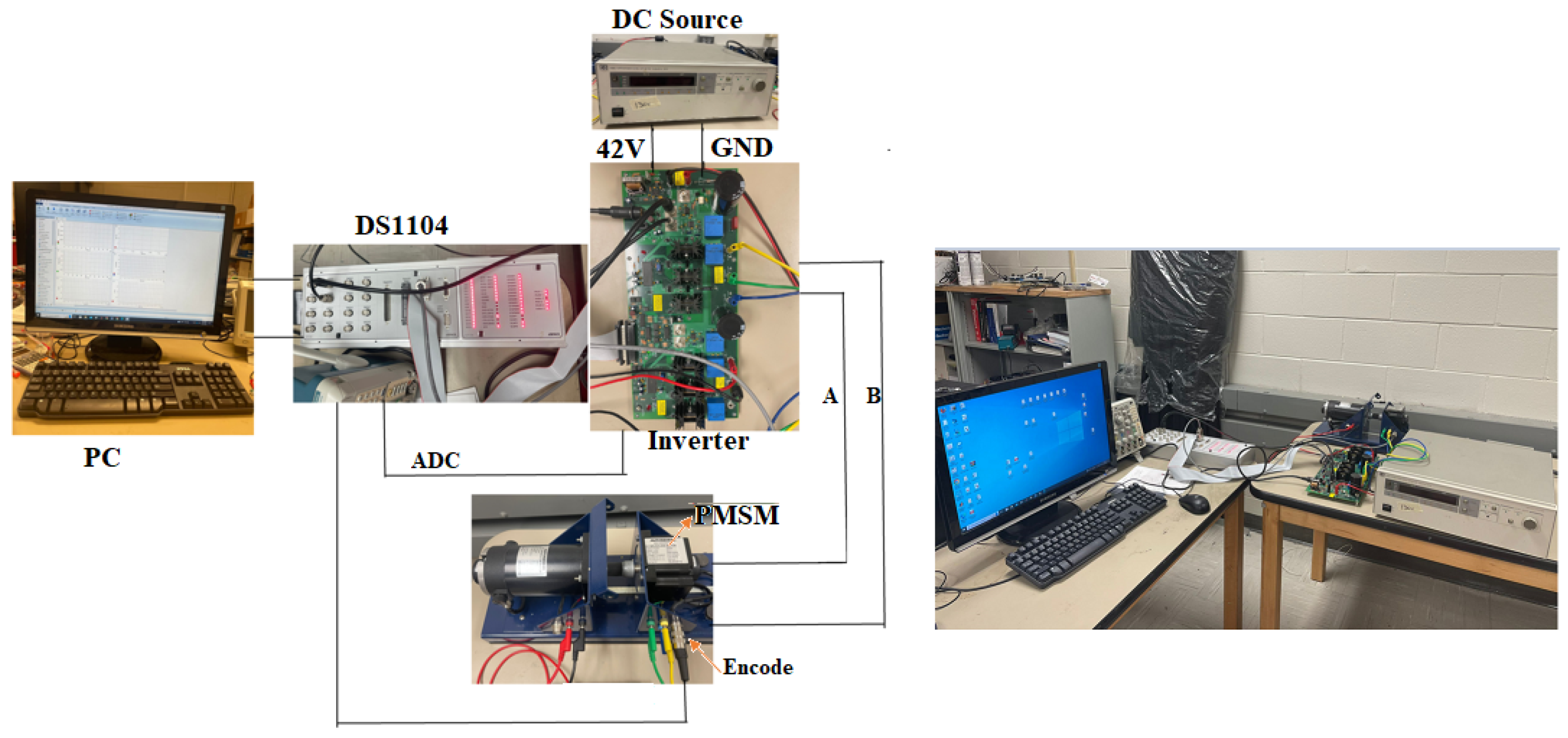
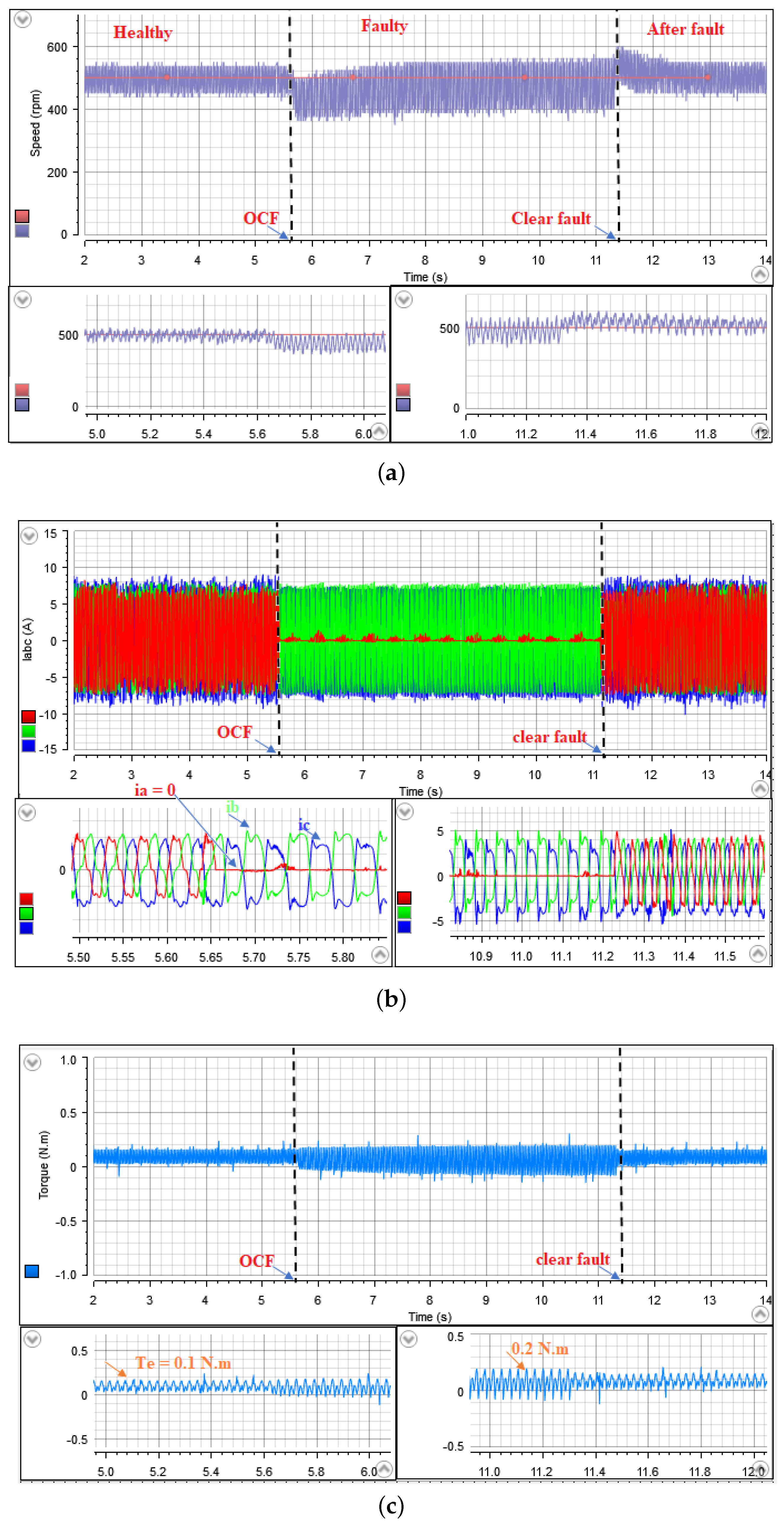
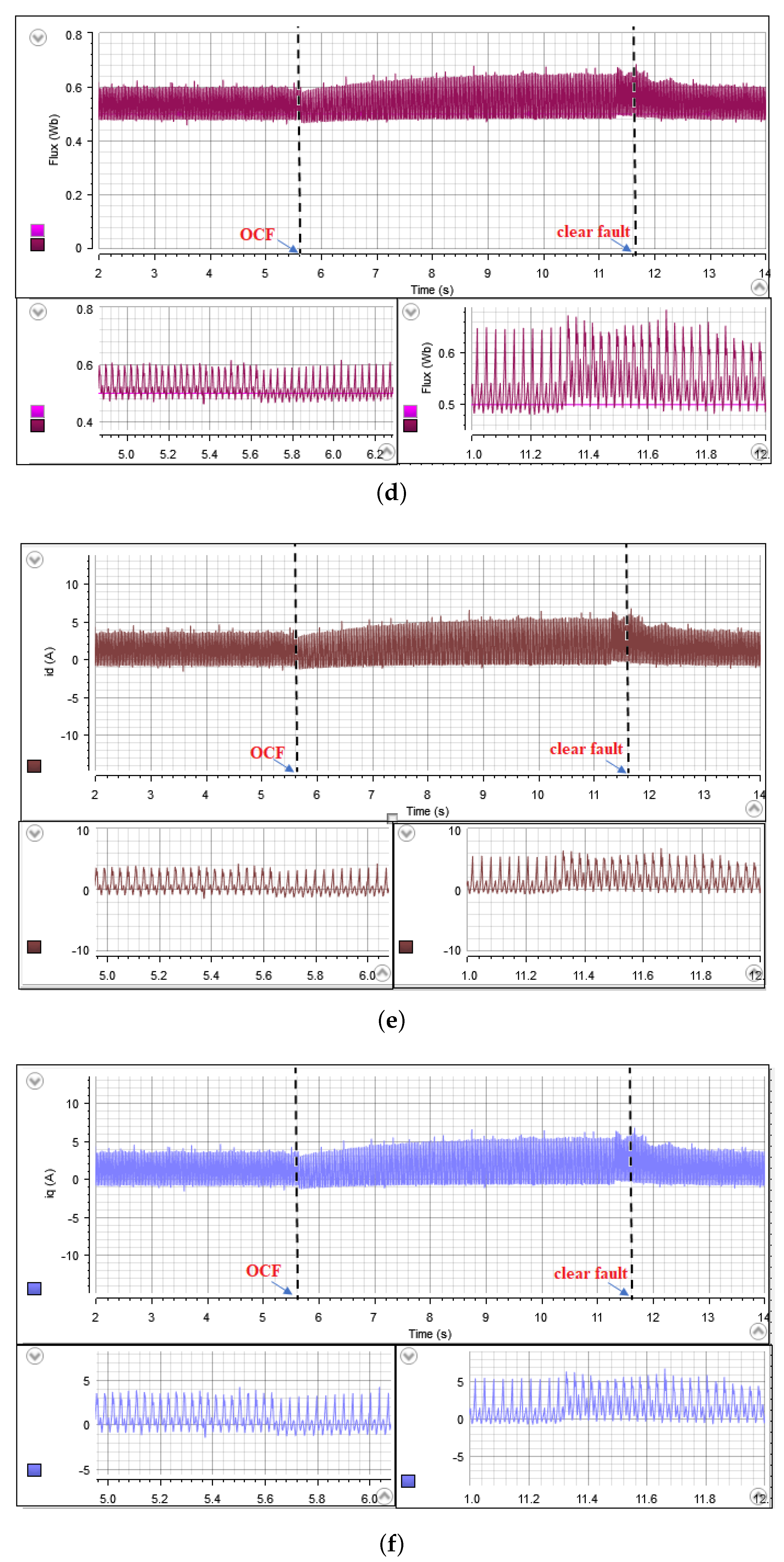
5.2. Experimental Results
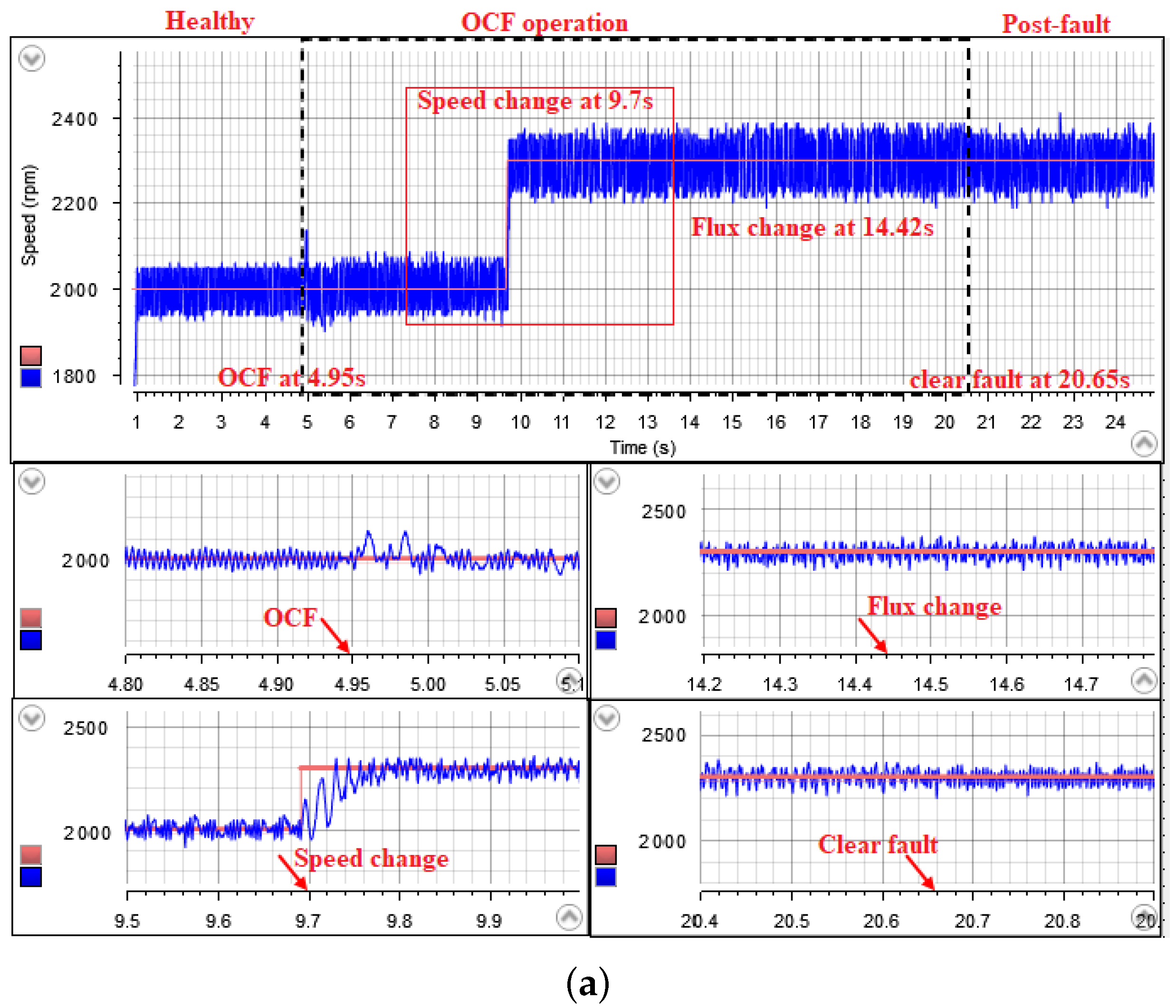
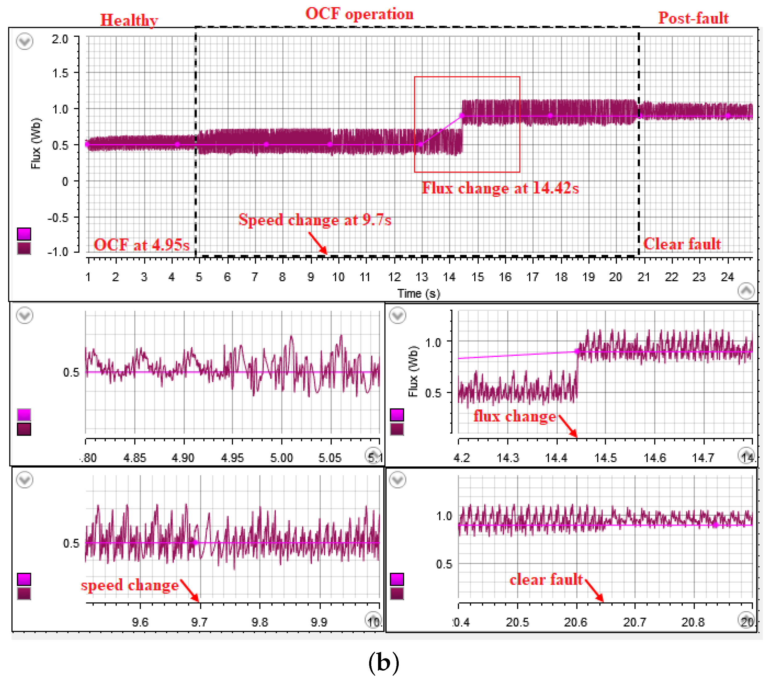
Decoupled Control Case Study
6. Conclusions
Author Contributions
Funding
Data Availability Statement
Conflicts of Interest
References
- Ghanayem, H.; Alathamneh, M.; Nelms, R.M. A comparative study of PMSM torque control using proportional-integral and proportional-resonant controllers. In Proceedings of the SoutheastCon 2022, Mobile, AL, USA, 26 March–3 April 2022; pp. 453–458. [Google Scholar]
- Stulrajter, M.; Hrabovcová, V.; Franko, M. Permanent Magnets Synchronous Motor Control Theory. J. Electr. Eng. 2007, 58, 79–84. [Google Scholar]
- Sakunthala, S.; Kiranmayi, R.; Mandadi, P.N. A Review on Speed Control of Permanent Magnet Synchronous Motor Drive Using Different Control Techniques. In Proceedings of the International Conference on Power, Energy, Control and Transmission Systems (ICPECTS), Chennai, India, 22–23 February 2018; pp. 97–102. [Google Scholar]
- Bida, V.M.; Samokhvalov, D.V.; Al-Mahturi, F.S. PMSM vector control techniques—A survey. In Proceedings of the IEEE Conference of Russian Young Researchers in Electrical and Electronic Engineering (EIConRus), Moscow/St. Petersburg, Russia, 29 January–1 February 2018; pp. 577–581. [Google Scholar]
- Ghanayem, H.; Alathamneh, M.; Nelms, R.M. Decoupled Speed and Flux Control of Three-Phase PMSM Based on the Proportional-Resonant Control Method. Energies 2023, 16, 1053. [Google Scholar] [CrossRef]
- Ghanayem, H.; Alathamneh, M.; Nelms, R.M. Three-phase PMSM vector control using decoupled flux and Speed Controller. Energy Rep. 2023, 9, 645–652. [Google Scholar] [CrossRef]
- Abassi, M.; Khlaief, A.; Saadaoui, O.; Chaari, A.; Boussak, M. Performance analysis of FOC and DTC for PMSM drives using SVPWM technique. In Proceedings of the 16th International Conference on Sciences and Techniques of Automatic Control and Computer Engineering (STA), Monastir, Tunisia, 21–23 December 2015; pp. 228–233. [Google Scholar]
- Korkmaz, F.; Topaloğlu, I.; Çakir, M.F.; Gürbüz, R. Comparative performance evaluation of FOC and DTC controlled PMSM drives. In Proceedings of the 4th International Conference on Power Engineering, Energy and Electrical Drives, Istanbul, Turkey, 13–17 May 2013; pp. 705–708. [Google Scholar]
- Dwivedi, S.; Singh, B. Vector Control vs. Direct Torque Control comparative evaluation for PMSM drive. In Proceedings of the Joint International Conference on Power Electronics, Drives and Energy Systems & 2010 Power India, New Delhi, India, 20–23 December 2010; pp. 1–8. [Google Scholar]
- Gupta, N.P.; Gupta, P. Performance analysis of direct torque control of PMSM drive using SVPWM—Inverter. In Proceedings of the IEEE 5th India International Conference on Power Electronics (IICPE), Delhi, India, 6–8 December 2012; pp. 1–6. [Google Scholar]
- Yue, Y.; Zhang, R.; Wu, B.; Shao, W. Direct torque control method of PMSM based on fractional order PID controller. In Proceedings of the 6th Data Driven Control and Learning Systems (DDCLS), Chongqing, China, 26–27 May 2017; pp. 411–415. [Google Scholar]
- Codreş, B.; Găiceanu, M.; Şolea, R.; Eni, C. Model predictive speed control of Permanent Magnet Synchronous Motor. In Proceedings of the International Conference on Optimization of Electrical and Electronic Equipment (OPTIM), Bran, Romania, 22–24 May 2014; pp. 477–482. [Google Scholar]
- Tang, M.; Zhuang, S. On Speed Control of a Permanent Magnet Synchronous Motor with Current Predictive Compen-sation. Energies 2019, 12, 65. [Google Scholar] [CrossRef] [Green Version]
- Fang, L.; Yushun, W.; Ruiqi, W. Simulation of speed-control system for PMSM based on sliding mode control. In Proceedings of the International Conference on Mechatronic Sciences, Electric Engineering and Computer (MEC), Shenyang, China, 20–22 December 2013; pp. 52–56. [Google Scholar]
- Rubino, S.; Bojoi, I.R.; Armando, E.; Tenconi, A. Deadbeat direct flux vector control of surface permanent magnet motor drives. IEEE Trans. Ind. Appl. 2020, 56, 2685–2699. [Google Scholar] [CrossRef]
- Sun, X.; Zhang, Y.; Lei, G.; Guo, Y.; Zhu, J. An improved deadbeat predictive stator flux control with reduced-order dis-turbance observer for in-wheel PMSMs. IEEE/ASME Trans. Mechatron. 2021, 27, 690–700. [Google Scholar] [CrossRef]
- Chen, J.; Wang, J.; Yan, B. Simulation Research on Deadbeat Direct Torque and Flux Control of Permanent Magnet Synchronous Motor. Energies 2022, 15, 3009. [Google Scholar] [CrossRef]
- Ton, T.-D.; Hsieh, M.-F. A Deadbeat Current and Flux Vector Control for IPMSM Drive with High Dynamic Performance. Appl. Sci. 2022, 12, 3789. [Google Scholar] [CrossRef]
- Vujji, A.; Dahiya, R. Speed Estimator for Direct Torque and Flux Control of PMSM Drive using MRAC based on Rotor flux. In Proceedings of the IEEE 9th Power India International Conference (PIICON), Sonepat, India, 28 February–1 March 2020; pp. 1–6. [Google Scholar]
- Yunhao, P.; Dejun, Y.; Yansong, H. The stator flux linkage adaptive SVM-DTC control strategy of permanent magnet synchronous motor. In Proceedings of the 6th Asia Conference on Power and Electrical Engineering (ACPEE), Chongqing, China, 8–11 April 2021; pp. 826–831. [Google Scholar]
- Ghanayem, H.; Alathamneh, M.; Nelms, R.M. Performance of a vector controlled PMSM drive based on proportional–resonance control under single-phase open circuit fault. Energy Rep. 2023, 9, 755–763. [Google Scholar] [CrossRef]
- Usman, A.; Doiphode, N.T.; Rajpurohit, B.S. Stator winding faults investigation in permanent magnet synchronous motor using motor signatures: Part I. In Proceedings of the 2019 International Conference on Electrical Drives & amp; Power Electronics (EDPE), The High Tatras, Slovakia, 24–26 September 2019; pp. 160–168. [Google Scholar]
- Sun, T.; Lee, S.H.; Hong, J.P. Faults analysis and simulation for interior permanent magnet synchronous motor using Simulink@ Matlab. In Proceedings of the 2007 International Conference on Electrical Machines and Systems (ICEMS), Seoul, Republic of Korea, 8–11 October 2007; pp. 900–905. [Google Scholar]
- Li, W.; Tang, H.; Luo, S.; Yan, X.; Wu, Z. Comparative Analysis of the Operating Performance, Magnetic Field, and Temperature Rise of the Three-Phase Permanent Magnet Synchronous Motor with or without Fault-Tolerant Control under Single-Phase Open-Circuit Fault. IET Electr. Power Appl. 2021, 15, 861–872. [Google Scholar] [CrossRef]
- Zhou, H.; Zhao, W.; Liu, G.; Cheng, R.; Xie, Y. Remedial field-oriented control of five-phase fault-tolerant permanent-magnet motor by using reduced-order transformation matrices. Energies 2017, 64, 169–178. [Google Scholar] [CrossRef]
- Feng, G.; Lai, C.; Li, W.; Tjong, J.; Kar, N. Open-Phase Fault Modeling and Optimized Fault-Tolerant Control of Dual Three-Phase Permanent Magnet Synchronous Machines. IEEE Trans. Power Electron. 2019, 34, 11116–11127. [Google Scholar] [CrossRef]
- Chen, Y.; Bao, Z.; Lin, C.; Zhao, X. Fault-tolerant SVPWM control strategy for five-phase PMSM under single-phase open-circuit fault. Energy Procedia 2019, 158, 2605–2610. [Google Scholar]
- Canseven, H.T.; Unsal, A. Performance improvement of a five-phase PMSM drive under open circuit stator faults. In Proceedings of the 2021 5th International Symposium on Multidisciplinary Studies and Innovative Technologies (ISMSIT), Ankara, Turkey, 21–23 October 2021. [Google Scholar]
- Iftikhar, M.H.; Park, B.-G.; Kim, J.-W. Design and analysis of a five-phase permanent-magnet synchronous motor for fault-Tolerant Drive. Energies 2021, 14, 514. [Google Scholar] [CrossRef]
- Tao, T.; Zhao, W.; He, Y.; Cheng, Y.; Saeed, S.; Zhu, J. Enhanced fault-tolerant model predictive current control for a five-phase PM motor with continued modulation. IEEE Trans. Power Electron. 2021, 36, 3236–3246. [Google Scholar] [CrossRef]
- Huang, W.; Du, J.; Hua, W.; Lu, W.; Bi, K.; Zhu, Y.; Fan, Q. Current-based open-circuit fault diagnosis for PMSM drives with model predictive control. IEEE Trans. Power Electron. 2021, 36, 10695–10704. [Google Scholar] [CrossRef]
- Scarcella, G.; Scelba, G.; Pulvirenti, M.; Lorenz, R.D. Fault-tolerant capability of deadbeat-direct torque and Flux Control for three-phase PMSM drives. IEEE Trans. Ind. Appl. 2017, 53, 5496–5508. [Google Scholar] [CrossRef]
- Wang, W.; Zhang, J.; Cheng, M. Common model predictive control for permanent-magnet synchronous machine drives considering single-phase open-circuit fault. IEEE Trans. Power Electron. 2017, 32, 5862–5872. [Google Scholar] [CrossRef]
- Krause, P.C.; Wasynczuk, O.; Sudhoff, S.D.; Pekarek, S.D. Analysis of Electric Machinery and Drive Systems; Wiley-IEEE Press: Piscatawy, NJ, USA, 2013. [Google Scholar]
- Campos-Delgado, D.U.; Pecina-Sánchez, J.A.; Espinoza-Trejo, D.R.; Arce-Santana, E.R. Diagnosis of open-switch faults in variable speed drives by stator current analysis and pattern recognition. IET Electron. Power Appl. 2013, 7, 509–522. [Google Scholar] [CrossRef]
- Ziegler, J.G.; Nichols, N.B. Optimum Settings for Automatic Controllers. J. Dyn. Syst. Meas. Control 1993, 115, 220–222. [Google Scholar] [CrossRef] [Green Version]
- Alathamneh, M.; Ghanayem, H.; Nelms, R.M. Power control of a three-phase grid-connected inverter using a pi controller under unbalanced conditions. In Proceedings of the SoutheastCon 2022, Mobile, AL, USA, 26 March–3 April 2022. [Google Scholar]
- Alathamneh, M.; Yang, X.; Nelms, R.M. Power control of a three-phase grid-connected inverter using a proportional-resonant control method under unbalanced conditions. In Proceedings of the IECON 2021—47th Annual Conference of the IEEE Industrial Electronics Society, Toronto, ON, Canada, 13–16 October 2021. [Google Scholar]
- Holmes, D.G.; Lipo, T.A.; McGrath, B.P.; Kong, W.Y. Optimized Design of Stationary Frame Three Phase AC Current Regulators. IEEE Trans. Power Electron. 2009, 24, 2417–2426. [Google Scholar] [CrossRef]


| Parameter | Value |
|---|---|
| Rated power | 200 W |
| Rated voltage | 42 V |
| Max speed | 3000 RPM |
| Voltage constant | 9.5 V/Krpm |
| Resistance (L-L) | 0.4 Ohms |
| Inductance (L-L) | 540 H |
| Pole-pairs number | 4 |
| Magnetic flux linkage | 0.01309 Wb |
Disclaimer/Publisher’s Note: The statements, opinions and data contained in all publications are solely those of the individual author(s) and contributor(s) and not of MDPI and/or the editor(s). MDPI and/or the editor(s) disclaim responsibility for any injury to people or property resulting from any ideas, methods, instructions or products referred to in the content. |
© 2023 by the authors. Licensee MDPI, Basel, Switzerland. This article is an open access article distributed under the terms and conditions of the Creative Commons Attribution (CC BY) license (https://creativecommons.org/licenses/by/4.0/).
Share and Cite
Ghanayem, H.; Alathamneh, M.; Nelms, R.M. Decoupled Speed and Flux Control of a Three-Phase Permanent Magnet Synchronous Motor under an Open-Circuit Fault Using a PR Current Controller. Energies 2023, 16, 5325. https://doi.org/10.3390/en16145325
Ghanayem H, Alathamneh M, Nelms RM. Decoupled Speed and Flux Control of a Three-Phase Permanent Magnet Synchronous Motor under an Open-Circuit Fault Using a PR Current Controller. Energies. 2023; 16(14):5325. https://doi.org/10.3390/en16145325
Chicago/Turabian StyleGhanayem, Haneen, Mohammad Alathamneh, and R. M. Nelms. 2023. "Decoupled Speed and Flux Control of a Three-Phase Permanent Magnet Synchronous Motor under an Open-Circuit Fault Using a PR Current Controller" Energies 16, no. 14: 5325. https://doi.org/10.3390/en16145325