1. Introduction
In recent decades, there has been a rapid advancement in microelectronic technology and the telecommunications industry, leading to increasingly integrated, miniaturized, and high-performance electronic components. However, while the internal power consumption of these devices has significantly increased, their physical dimensions have been continuously shrinking [
1]. Consequently, there is a challenge in efficiently dissipating the high heat flux generated by chips within confined spaces in a timely manner [
2,
3]. Elevated temperatures resulting from inadequate heat dissipation can lead to electronic component failures and pose serious safety hazards. To address this issue, ultra-thin two-phase heat transfer devices have gained widespread use in portable electronic devices due to their large heat dissipation area, high heat transfer efficiency, and lightweight characteristics.
The wick plays a crucial role in two-phase heat transfer devices, serving as both the driving force behind the circulation of the working fluid and the main source of resistance to fluid flow. In ultra-thin heat pipes and vapor chambers, as the thickness decreases, the vapor space and wick thickness also decrease significantly, especially when the thickness is less than 0.3 mm. Even slight variations in thickness can result in a sharp increase in thermal resistance, often exponentially [
4,
5]. Therefore, it is essential for the wick to maintain optimal capillary performance while minimizing its thickness as much as possible.
Wire mesh wicks are currently the most widely used type of wicks in commercial applications due to their various advantages, including multiple pore size options, easy processing, low cost, and high permeability. Many researchers have incorporated wire mesh wicks into ultra-thin two-phase heat transfer devices. Sintered wire mesh wicks typically exhibit relatively high permeability. Aoki et al. [
6] first developed sintered copper mesh wicks for ultra-thin heat pipes with thicknesses of 1.0 mm and 0.7 mm, which exhibited high maximum heat transfer capacities of 20 W and 7 W, respectively, in narrow spaces. The minimum thermal resistances achieved were 0.2 °C/W and 0.4 °C/W. Zhou et al. [
5] prepared multi-layered wicks made of sintered copper mesh with 100- and 180- mesh, allowing for the adjustment of the liquid-to-vapor channel area ratio by varying the wick’s width. Chen et al. [
7] made a multilayer composite micromesh wick, comprised of coarse and fine meshes with different layer combinations, and with an equilibrated wicking height at 55.98 mm. Tang et al. [
8] used a three-layer wire mesh as the wick structure to fabricate high-temperature cylindrical heat pipes with anti-gravity performance. Wang et al. [
9] utilized five different specifications of single-layer copper mesh within the range of 120–220 mesh as the wicks to fabricate ultra-thin heat pipes with a thickness of 1 mm. Among them, the copper mesh with a mesh size of 180 exhibited an optimal heat transfer performance, significantly reducing the evaporator temperature and demonstrating anti-gravity performance. However, due to their regular structure, they often suffer from the drawback of low capillary action, which hinders the efficient reflux of the working fluid. Currently, most wire mesh wicks use multiple layers of copper mesh or chemical modification methods to improve the structure and meet the requirements of capillary performance. Lv et al. [
10] fabricated an ultra-thin flat heat pipe with a thickness of 0.95 mm, using a superhydrophilic sintered copper mesh wick internally. This design provided strong capillary forces and low flow resistance. Compared to copper plates, the evaporator temperature and thermal resistance of these ultra-thin flat heat pipes were significantly lower, demonstrating an excellent heat transfer performance. Zhou et al. [
11] employed a special porous spiral structure wire mesh as the wick and found that it exhibited much a higher capillary performance compared to traditional wire mesh structures. Xu et al. [
12] utilized copper mesh modified with nanostructures as the capillary core structure for ultra-thin heat pipes, resulting in a significant improvement in the heat flux density of the heat pipes. Cheng et al. [
13] report a novel strategy to realize the controllable water permeation on the mixed thiol modified nanostructured copper mesh films.
Regarding the methods mentioned above, the approach of superimposing multiple layers of copper mesh enhances the capillary force but also increases the overall thickness. While this method may be effective in certain applications, it presents challenges when working within a limited space, as it increases the thickness of the device and reduces the available vapor flow space. Moreover, the wick structure in two-phase phase change devices requires adequate strength and stability to withstand long-term cycles of operation. On the other hand, in a two-phase heat exchange device, the wick structure serves not only to facilitate the return flow of the liquid, but also to facilitate the phase change heat transfer during evaporation/boiling and condensation at the interface. Therefore, the wick’s surface plays a crucial role in enhancing the phase change heat transfer and overall thermal performance. It is essential to strike a balance between the capillary force, thickness, strength, and thermal performance when constructing an effective wick for two-phase heat transfer applications.
In previous research, we discovered that the biomimetic copper forest structure, due to its abundant dendrites, exhibits superhydrophilic characteristics and high capillary features. At same time, it shows excellent heat transfer performance at boiling and in ultra-thin heat pipes [
14,
15,
16]. Therefore, this paper combines the biomimetic copper forest structure with copper mesh to fabricate a composite ultra-thin wick with a high capillary performance. The copper forest structure is deposited on the surface of the copper mesh using electrodeposition, resulting in a copper forest modified copper mesh wick. The morphology and capillary performance of the modified wick are characterized and studied in this paper. Furthermore, to further investigate the mechanism of the copper forest structural modification on the capillary performance of the copper mesh, the capillary rising process of both the copper mesh wick and the copper forest modified copper mesh wick is analyzed through visualization.
3. Results and Discussion
3.1. The Morphological Features of CFMW
The information about the CFMW samples is presented in
Table 2. The data are drawn in
Figure 5; as the electrodeposition time increases, the thickness of the wick grows. Similarly, reducing the wire diameter also leads to an increase in wick thickness. Although the porosity remains relatively stable, there is a slight improvement observed after modification.
The left side of
Figure 6 shows the typical copper mesh and the biomimetic copper forest structure. The copper mesh, as the most widely used wick structure, has advantages such as high permeability, strong stability, and ease of acquisition due to its large pore structure. However, single-layer copper mesh usually has a poor capillary performance, requiring multiple layers to increase the capillary force, which leads to an increased thickness. The biomimetic copper forest structure, with its vertical dendrites structure and rich secondary and tertiary nanostructures, forms abundant dendrites in the upper part and interconnected channels in the lower part, creating a connected “Ω” shaped channel. At the same time, the nanoscale pores formed between the secondary and tertiary branches provide a larger capillary force, and the “Ω” shaped channel structure effectively increases the permeability of the structure and reduces resistance during liquid flow [
16]. However, when reducing the thickness of the biomimetic copper forest structure, it usually sacrifices permeability while maintaining a high capillary force. By combining the advantages of the copper mesh structure and the biomimetic copper forest structure, the high permeability of the copper mesh and the high capillary force of the biomimetic copper forest structure can be utilized, while significantly reducing the thickness of the wick to meet the requirements of ultra-thin heat dissipation devices.
Figure 6 illustrates the morphological structure of the CFMWs. From top to bottom are the #1, #2, and #3 specifications of the copper mesh, and from left to right are the electrodepositions for 100 s, 120 s, and 150 s. The copper wires intersect to form micrometer-scale pores that serve as channels for liquid reflux. The copper forest structure deposited on the copper wires comprises nanoscale copper particles, and the interlocking voids created by the branching pattern provide the abundant capillary force. Due to the shielding effect, no deposited copper is observed at the intersections of the copper wires and beneath the copper foil substrate. Copper dendrites is only deposited on the copper wires. When viewed from left to right, for the same specification of copper mesh, the thickness of the deposited copper dendrites significantly increases with longer deposition times, forming elongated layers resembling dispersed hedgehogs. Shorter deposition times result in shorter dendrites. When viewed from top to bottom, for the same electric charge, the thinner the diameter of the copper wires in the copper mesh, the thicker the deposited copper dendrites and the longer the dendrites. In contrast, when the diameter of the copper wires is thicker, only small copper particles are deposited, resulting in a thinner layer on the copper wires.
3.2. The Capillary Performance of MWs and CFMWs
To determine the improvement in capillary performance of the CFMWs and further optimize the ratio between the MWs and the CFMWs, capillary rising tests were conducted on the samples made as described above. The capillary performance parameters and capillary rising curves when ethanol was used as the working fluid are shown in
Figure 7.
It can be observed that the CFMWs at different time intervals have different effects on the three types of MW. For #1 MW with a smaller wire diameter, the deposition of copper forest dendrites is more significant under the same applied charge, leading to an increase in the thickness of the deposition layer. Simultaneously, the capillary performance of the wick also increases. This indicates a good proportion between the pore size and the deposited dendrites. As the thickness of the deposition layer increases, the nano-scale dendrite structure can provide higher and more abundant capillary forces. However, due to the relatively smaller copper pore size, the volume of fluid flow channels decreases, resulting in a slight decrease in permeability. Nonetheless, within the experimental range, the longer the deposition time, the better the capillary performance. At a deposition time of 150 s, the ΔPc·K value of the CFMW reaches 8.44 × 10⁻⁸ N. After copper forest modification, the capillary forces of the wicks significantly increased from the original 777 Pa to 1100–1400 Pa, while the permeability remained relatively unchanged. The capillary pressure drops of CFMWs are 1.45, 1.62, and 1.8 times than that of MWs. Therefore, it can be concluded that the appropriate copper forest modification can further enhance the capillary forces of the MW while maintaining its original permeability, thereby achieving an overall improvement in capillary performance.
For the #2 and #3 MWs with slightly larger pore sizes, when the deposition time is short (100 s, 120 s), only shorter “bush-like” dendrites is deposited, leading to a limited enhancement in capillary performance. The thickness of the deposition layer shows a linear increase with the increase in deposition time. When the deposition time reaches 150 s, lateral branches start to grow on the dendrites, resulting in a significant improvement in the capillary forces and a noticeable enhancement in overall capillary performance. The ΔPc·K values for #2F3 and #3F3 reach 6.21 × 10⁻⁸ N and 8.21 × 10⁻⁸ N, respectively. Within the experimental range, samples #1F3, #2F3, and #3F3 exhibit the best capillary performance, reaching 8.44 × 10⁻⁸ N, 6.41 × 10⁻⁸ N, and 8.21 × 10⁻⁸ N, respectively, which are 1.7, 1.2, and 1.6 times higher than the unmodified MWs (#1, #2, #3).
Comparisons of the Δ
Pc·K values of the MWs and the CFMWs with other wick structures are shown in
Figure 8 [
16,
18,
19,
20,
21,
22,
23,
24,
25,
26,
27,
28,
29]. The CFMWs exhibit superior capillary performance at an ultra-thin thickness, especially superior sintered meshes. At a thickness of 142 μm, the Δ
Pc·K value can reach 2.9 times that of the 450 μm composite parallel woven spiral woven wick.
3.3. The Microscopic Flow Analysis for the Liquid in Wicks
To verify the improvement mechanism, visual analysis was conducted through a high-speed camera with a microscope lens to capture the images of the liquid rising process in both the MW and the CFMW.
Figure 9a shows the liquid rising process of the MWs. When the liquid flows inside the wick, it is subjected to four forces: upward capillary force (dynamic force), downward gravity, viscous force, and inertia force (resistance). In general, the inertia force can be neglected due to its small magnitude. In the initial stage, the gravitational force acting on the working fluid is small, so under the influence of capillary force, the working fluid rises rapidly. As the rising time increases, the working fluid undergoes a transition from ascending in a continuous column (0–60 ms) to flowing from right to left along the copper mesh grid (80–160 ms). This change occurs because, with increasing height, the gravitational force acting on the working fluid becomes more significant. Simultaneously, the capillary force weakens due to the larger aperture of the copper mesh. As a result, the climbing force exerted on the working fluid becomes insufficient, requiring it to fill the entire grid before resuming its ascent. This leads to a significant decrease in the liquid rising rate. In the MW, as the working fluid climbs from the first row to the fourth row, its volumetric flow rate decreases from 171 μm
3·s
−1 to 64 μm
3·s
−1.
Figure 9b shows the liquid rising process of the CFMW. The working fluid climbs rapidly under the action of capillary force, ascending from bottom to top, without the phenomenon of flowing along the grid. This behavior can be attributed to the enhanced capillary force provided by the copper forest structure, which directs the working fluid to flow along the dendrites rather than the copper wires. As the height increases, the climbing rate does not decrease significantly, and the liquid level continues to rise uniformly and steadily from 100 ms to 160 ms. Even when the working fluid reaches higher positions and experiences increasing gravity, the substantial capillary force attracts the liquid to replenish through the lower copper forest dendrites. This replenishment process maintains the climbing rate of the working fluid.
From
Figure 9, it is evident that the modification of the copper mesh structure results in the dendritic structure covering the surface of the copper wires, slightly reducing the space within the copper grid. However, upon closer inspection of the pink circle in
Figure 9, it can be observed that during the liquid rising process, the liquid first appears between the gaps among the copper wires, and then it fills the holes within the MW. This observation suggests that the capillary force of the copper mesh primarily relies on the tiny gaps between the copper wires. Similarly, in the case of the CFMW, the liquid also initially appears in the dendritic parts of the structure. Once the dendritic parts are completely infiltrated, the larger pores within the MW are filled with the liquid. Hence, the improvement in capillary performance of the modified copper mesh can be attributed mainly to the presence of dendrites. The large pores of the copper mesh provide flow channels for the flow of the liquid.
By examining
Figure 7a,b together, it is evident that there is a noticeable change in capillary performance before and after the modification. The modification significantly enhances the capillary force. However, when considering permeability, the change is relatively small, with a maximum of 25% (#1–#1F2). Nevertheless, the overall capillary performance is improved. Therefore, the utilization of the copper forest structure modification can significantly enhance the overall capillary performance. In summary, the copper forest modification can provide a richer capillary force, greater driving force, while maintaining the high permeability of the copper mesh, thereby enhancing its overall capillary performance.
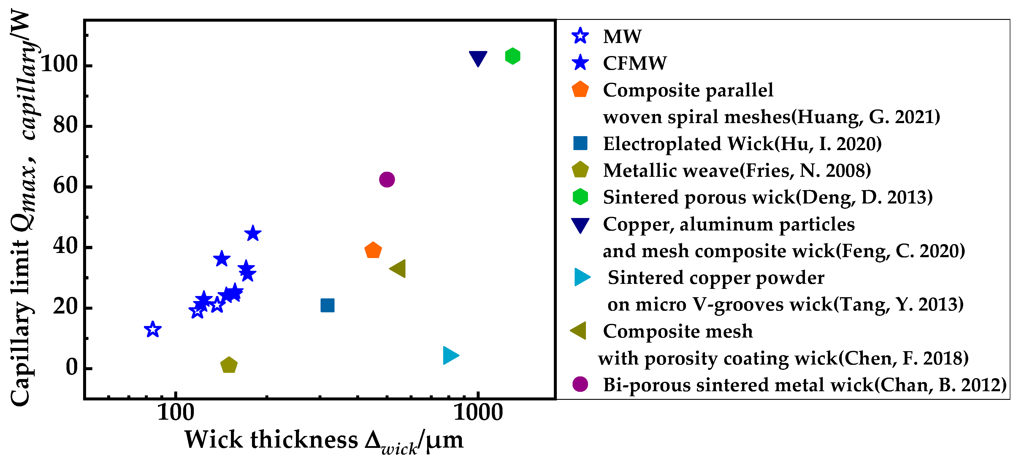
3.4. The Capillary Limit of the Wicks
The capillary performance of the wick plays a critical role in determining its heat transfer capacity. During the operation of a heat pipe, in order for the heat pipe to operate, Equation (12) must be satisfied. The wick’s capillary performance sets the boundaries for providing a sufficient driving force to facilitate the circulation of the working fluid. Consequently, it imposes limitations on the operation of ultra-thin heat pipes and directly affects their heat transfer capacity. This limitation is referred to as the capillary limit [
30]. An expression for the maximum flow rate
may readily be obtained in Equation (13), and the corresponding heat transport is given by Equation (14), when the angle of inclination angle of heat pipe
Ψ is 0, it can be drawn as Equation (15) [
30]. The operation of ultra-thin heat pipes is mainly constrained by the capillary limit, which indirectly reflects the heat transfer capacity of the ultra-thin heat pipes. The capillary limit of the wick is calculated according to Equation (15) [
30].
Here,
ρl represents the density of water,
σ is the surface tension of water,
μl is the viscosity of working fluid,
Leff denotes the effective length,
Awick is the cross-sectional area of the wick,
Reff represents the effective capillary radius, and
hfg is the latent heat of evaporation. Assuming
Awick as the cross-sectional area of the liquid wick structure (Δ
wick × 3 cm) instead of the cross-sectional area of the heat pipe, and taking
Leff as 9 cm, the capillary limit for MWs and CFMWs is calculated as shown in
Figure 10. The capillary limit of the CFMWs is 1.2–2.8 times that of the unmodified copper mesh wick.
Figure 11 presents the capillary limits of different liquid wick structures. Compared to the composite parallel woven spiral mesh structure, the CFMW structure reduces the thickness by 68% while maintaining the same capillary limit (36 W). The CFMW can provide a significantly higher capillary limit at an ultra-thin thickness, which greatly reduces the thickness of the heat pipe and facilitates the preparation of ultra-thin heat pipes.
4. Conclusions
This study employed an electrochemical deposition method to deposit a series of biomimetic copper forest modified copper mesh wicks on three different specifications of copper mesh (250 mesh, 200 mesh, 150 mesh) for deposition times of 100 s, 120 s, and 150 s, respectively. The morphology characterization and capillary performance testing were conducted on these wicks. For all three copper mesh structures, the capillary performance increased with an increasing deposition time. The ΔPc·K values of the CFMWs for the three specifications reached 8.44 × 10⁻⁸ N, 6.41 × 10⁻⁸ N, and 8.21 × 10⁻⁸ N, which were 1.7, 1.2, and 1.6 times higher than those of the unmodified MWs. Compared to other wick structures, the ΔPc·K value of the CFMWs was 2.9 times higher than that of the 450 μm composite parallel woven spiral woven wick at a thickness of 142 μm. Compared to the composite parallel woven spiral woven structure, the CFMW structure reduces the thickness by 68% while maintaining the same capillary limit (40 W).
Analysis of its flow performance characteristics revealed that the deposition of nanoscale copper particles in the form of copper forest structures introduced dendrite and crisscrossing holes that enhanced the capillary action of the wick, and the big pores of the mesh provide the flow path for the liquid. Therefore, copper forest modification can provide a greater capillary force and working fluid replenishment while maintaining the high permeability characteristics of the copper mesh, thus improving its overall capillary performance.


