Article

Pitting and Strip Corrosion Influence on Casing Strength of Salt Cavern Compressed Air Energy Storage

1
China Energy Digital Technology Group Co., Ltd., Beijing 100044, China
2
CNPC Engineering Technology R&D Company Limited, Beijing 102206, China
3
School of Mechanical Engineering, Yangtze University, Jingzhou 434023, China
4
Beijing Petroleum Machinery Co., Ltd., Beijing 102206, China
*
Author to whom correspondence should be addressed.
Energies 2023, 16(14), 5362; https://doi.org/10.3390/en16145362
Submission received: 23 April 2023 / Revised: 29 May 2023 / Accepted: 5 June 2023 / Published: 14 July 2023
(This article belongs to the Special Issue Advances in the Utilization of Underground Energy and Space)

Abstract

:
In response to the localized corrosion generated by underground casing, which seriously affects the safe operation of salt cavern compressed air storage, we used commercial finite element software, ANSYS, to propose a partial model applicable to casings with pitting and strip corrosion. The results show that the pitting depth of the casing is closely related to fracture and collapse pressure. As pitting corrosion depth increases, its effect on fracture and collapse pressure becomes more significant. The greater the number of corrosion pits, the lower the compressive strength of the casing, and the casing tends to be more prone to fracture. The area with large stress is mainly distributed along the long axis of the strip corrosion. In the short axis of the strip corrosion, there is no stress concentration and appears as a low stress region. The effect of strip corrosion depth on failure pressure is greater than the effect of strip corrosion length. In this work, we developed a method to predict residual strength, which is useful to assess not only well integrity but, additionally, safety of the casing used during petroleum and natural gas exploration and production.

1. Introduction

Electricity generated from traditional energy sources such as coal, oil and natural gas is already facing serious environmental problems and economic pressures. At the same time, emission restrictions, rising prices and tight supplies are forcing attempts to find alternatives. A new power system that relies on renewable energy sources is a clean, sustainable and environmentally friendly power system. The system relies on a variety of renewable energy sources including solar, wind, hydro and geothermal to produce electricity and supply it to people. It produces no air or water pollution, no greenhouse gases, and is more sustainable because the constant flow of renewable energy reduces dependence on finite energy sources such as oil and natural gas. In addition, this type of power system is less expensive to operate, more stable and more diverse in where it uses renewable energy, regardless of geography, season, etc.
The new power system, primarily relying on renewable energy, constitutes a significant approach to accomplish the strategic objective of “carbon peaking and carbon neutral” [1]. However, the intermittent, unpredictable and cyclical nature of renewable energy poses limitations on grid integration and utilization [2,3]. Compressed Air Energy Storage (CAES) presents a viable solution to effectively mitigate these challenges. That is, during low power consumption hours, electricity is used to compress air to high pressure and stored in underground caverns at 300–1500 m, so that electricity is converted into the internal energy of air and stored; during peak power consumption hours, high pressure air is released from the underground storage caverns into the combustion chamber and heated up by fuel combustion to drive turbines to generate electricity.
Currently, underground compressed air energy storage is primarily categorized into four forms: aquifer, depleted reservoir, lined rock caverns and salt cavern [4,5].
Aquifer compressed air energy storage harnesses the potential of underground aquifers as storage reservoirs, compressing and storing air in rock formations or permeable formations using compressors. When energy is needed, the stored compressed air is released to drive a generator and generate electricity. One notable advantage is the elimination of the need for a separate gas storage well. However, it also has limitations due to geological conditions, limited gas storage capacity and high investment costs.
Depleted reservoir compressed air energy storage makes use of abandoned coal mines as storage reservoirs, where air is compressed within the coal mine using compressors. The stored compressed air is then released to drive a generator, generating electricity as needed. On the other hand, it boasts a significant gas storage capacity. However, it is important to note that there may be inherent gas safety risks associated with utilizing coal mines for storage in this manner.
Lined rock cave compressed air storage, similar to above, is generally constructed by conventional mining techniques (shaft sinking, blasting or excavation). The stratum itself is rocky and compact, or it is made compact by adding a water curtain system, installing engineered liners. It is a natural underground cavern structure that can store air without taking up ground space, and therefore, does not have much impact on land use. However, it has the disadvantage of limited number and location and small storage capacity.
Salt cavern compressed air energy storage (SCCAES) refers to the use of electrical energy compressed air in the grid load low valley. Its high pressure is sealed in the underground salt cavern, and then compressed air is released to drive the air turbine to generate electricity during the peak load, which can realize the functions of power system peak shaving and emergency response [6,7]. This energy storage method has low cost, large storage capacity, reliable technology and long operational life [8,9]. It is one of the key technologies for regulating the imbalance between supply and demand in energy systems in the future [10].
The above four forms of underground compressed air energy storage are different, but the basic principles are the same. As shown in Figure 1, a complete compressed air system includes three key parts: surface equipment, wellbore and underground space [11], and the surface equipment consists of five key parts, such as compressors, coolers, heat returners, turbines and generators, among which, the compressor is compressing air to realize the conversion of electrical energy into internal air energy. Air pressure is usually up to 70–100 bar and temperature up to 1000 °C. The cooler is the heat exchange equipment, mainly used for cooling and preventing the air from decreasing in pressure in the cavern. The recuperator is the heat exchange equipment or combustion chamber that raises the air temperature to about 1000 °C to keep the turbine running consistently and steadily for a long time in order to improve the turbine efficiency. The turbine is a turbine through which the air is depressurized to convert the internal energy into kinetic energy. A generator is the conversion of kinetic energy into electrical energy, usually a synchronous generator.
The wellbore serves a dual purpose as a key piping system connecting the surface to the underground salt cavern: to transport air from the surface compressor to the salt cavern for storage and to release compressed air from the salt cavern to the surface for power generation [12]. Among the various components of a wellbore, the casing is a type of pipe widely used in wellbores and is usually made of metal or plastic. Its main role is to protect the well wall, control fluids in the wellbore, and provide a support structure. The casing plays a pivotal role as a core part of the wellbore and has a significant impact on the safety and reliability of the entire system [13,14]. Therefore, the integrity of the casing is of utmost importance as it can determine the success or failure of the entire compressed air storage system.
Figure 1. Schematic diagram of surface equipment, wellbore and underground space.
Energies 16 05362 g001
Oxygen corrosion is an extremely serious electrochemical corrosion, compared with other corrosion types, oxygen corrosion is also the most significant, will bring a certain threat to the safe operation of pipelines and other related equipment. Casing corrosion caused by oxygen is a common issue in SCCAES, particularly in high temperature, high pressure, and high salt content environments. This corrosion can lead to structural damage to the casing, compromising its integrity and reliability and posing potential risks to the safety and stability of the CAES system. Therefore, it is crucial to carefully analyze the role of casing corrosion and implement effective preventive measures, such as selecting corrosion-resistant materials, applying coatings and monitoring brine quality to ensure the reliable operation of the SCCAES system.
In view of the special geological conditions of salt mines in China, compressed air energy storage has put forward higher requirements for the stability of the wellbore after the completion of cavity modification; therefore, it is urgent to solve the engineering and technical problems of corrosion resistance of salt cavity energy storage casing devices [15,16]. Around casing corrosion, many scholars have done a lot of research. Shi et al. [17] established a casing tubercular corrosion model. Based on the residual strength of casing damaged by tubercular corrosion assessed using elastic–plastic finite element method, changes of collapse and tensile resistance—as well as burst strength of casings—were analyzed. Che et al. [18] studied the affection influence on casing strength from stress concentration caused by corrosion cavity. Based on the knowledge of plasto-elasticity, a mathematical model which can calculate the stress concentration factor caused by corrosion cavity was established. Additionally, a mathematical model which can calculate the residual intensity of casing after corrosion was also established. Wang et al. [19] calculated the collapse strength and burst strength of corroded casings, and predicted the safe service life of casings. Nabipour et al. [20] established a coupling plane model of wellbore, studied the influence of internal pressure, horizontal stress difference and casing eccentricity on wellbore. Through theory and simulation verification, Zhu et al. [21] Xiaohua developed a numerical model, and used finite element method (FEM) to analyze casing collapsing strength with varieties of corrosion defects.
In this paper, we report residual strength of a casing damaged by both pitting and strip corrosion, which was studied using ANSYS finite element analysis method. The main emphasis of this analysis was erosion pits number and how strip corrosion depth and length affected casing strength. We expect that results of this study will establish a theoretical foundation to assess safety of the corroded casings during gas and oil exploration.

2. Failure Criterion

Assuming that the casing is subjected to uniform external pressure, according to the thick-walled cylinder theory of elastic mechanics, the planar force diagram of the thick-walled cylinder is shown in Figure 2. Neglecting the axial pressure, the axial length can be regarded as infinite. Then, the thick-walled cylinder on the force at any radius r can be Lame formula [22].
σ r = r 1 2 r 2 2 r 1 2 1 r 2 2 r 2 q 1 r 2 2 r 2 2 r 1 2 1 r 1 2 r 2 q 2 σ ρ = r 1 2 r 2 2 r 1 2 1 + r 2 2 r 2 q 1 r 2 2 r 2 2 r 1 2 1 + r 1 2 r 2 q 2
where: σ r is Radial stress (MPa); σ ρ is circumferential stress (MPa); r 1 is the inner radius of the casing (mm); r 2 is the outer radius of the casing (mm); r is the distance from the axis of the casing to any point on the pipe wall (mm); q 1 is the pressure inside the casing (MPa) and q 2 is the pressure outside the casing (MPa).
Residual resistance strength of the corroded casing according to the ASME FFS-1 standard can be calculated as shown below [23].
p t = 2 σ s D δ v ω 1 D δ v ω 2
where p t is residual resistance strength (MPa); σ s is casing yield strength (MPa); D is casing outer diameter (mm); δ is casing nominal wall thickness (mm); v is corrosion velocity (mm/a) and ω is the service time (a).
Two failure criteria are typically used [4], and they depend on the failure modes: (1) elastic failure implies casing failure when the equivalent stress in corrosion areas reaches the yield strength of the casing string. In this work, we adopted Von Mises equivalent stress mode. (2) Plastic failure occurs during casing failure when the minimum stress in corrosion areas reaches the tensile strength of the casing string.
Failure criterion is the basis for assessing the failure, depending on the failure mode. Oil and gas casing generally use the pipe with plastic. Therefore, the failure of the pipe is generally plastic failure. That is, when the equivalent stress (Von mises conditions) of corrosion defect area reaches the yield limit, the pipe will be a failure. This paper adopts the criterion based on this plastic failure. The plastic failure criterion is that the minimum equivalent stress of corrosion defect area should be determined by the fourth strength theory.
The Von Mises condition in three-dimensional principal stress space can be expressed as:
σ v = 1 2 [ ( σ 1 σ 2 ) 2 + ( σ 2 σ 3 ) 2 + ( σ 1 σ 3 ) 2 ] [ σ ]
where σ v and [ σ ] are is Von Mises equivalent and allowable stresses (MPa) and σ 1 , σ 2 , σ 3 are main stresses (MPa) in X ,   Y ,   Z directions, respectively.
In the finite element model, the equivalent stress of casing under different defect size can be calculated, and ultimate load of casing can be analyzed to compare its residual strength. The greater the equivalent stress, the smaller the residual strength of pipeline, and the more prone to corrosion failure.

3. Strength Analysis of Corroded Casing under Internal Pressure

Based on mechanism, corrosion is typically divided into uniform and localized corrosion types. In the case of a uniform corrosion, casing walls become thinner and can be calculated according to the thinning casing. Local corrosion includes pitting corrosion, strip corrosion and perforation corrosion. Pitting corrosion forms round pits in the inner wall of the casing. Strip corrosion usually forms a strip in the axial direction. Perforation corrosion causes casing to leak. Corrosion can cause accidents, and the residual strength of the corroded pipe needs to be accurately evaluated. In this work, for implication of the FE analysis, we only considered pitting and strip corrosion types. Thus, this work studied how pitting and strip corrosion affects mechanical behavior of casings.

3.1. Strength Analysis of Casing with Pitting Corrosion Defects

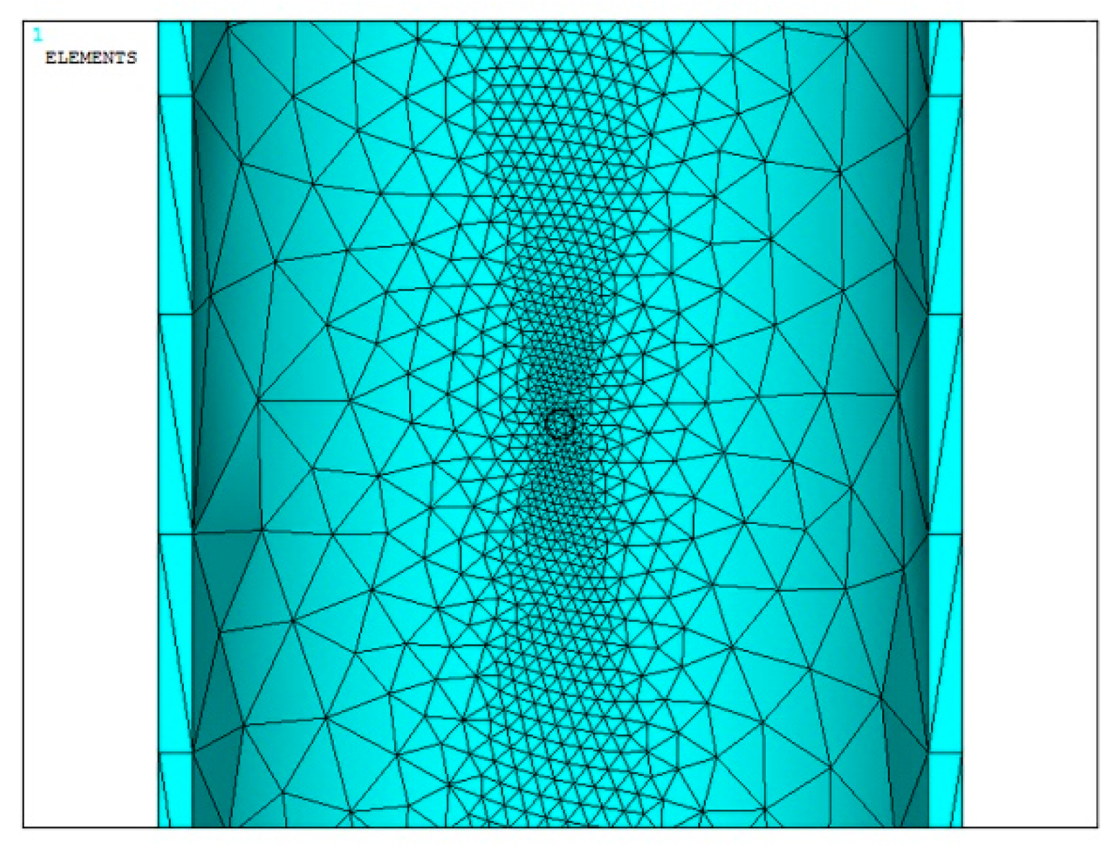
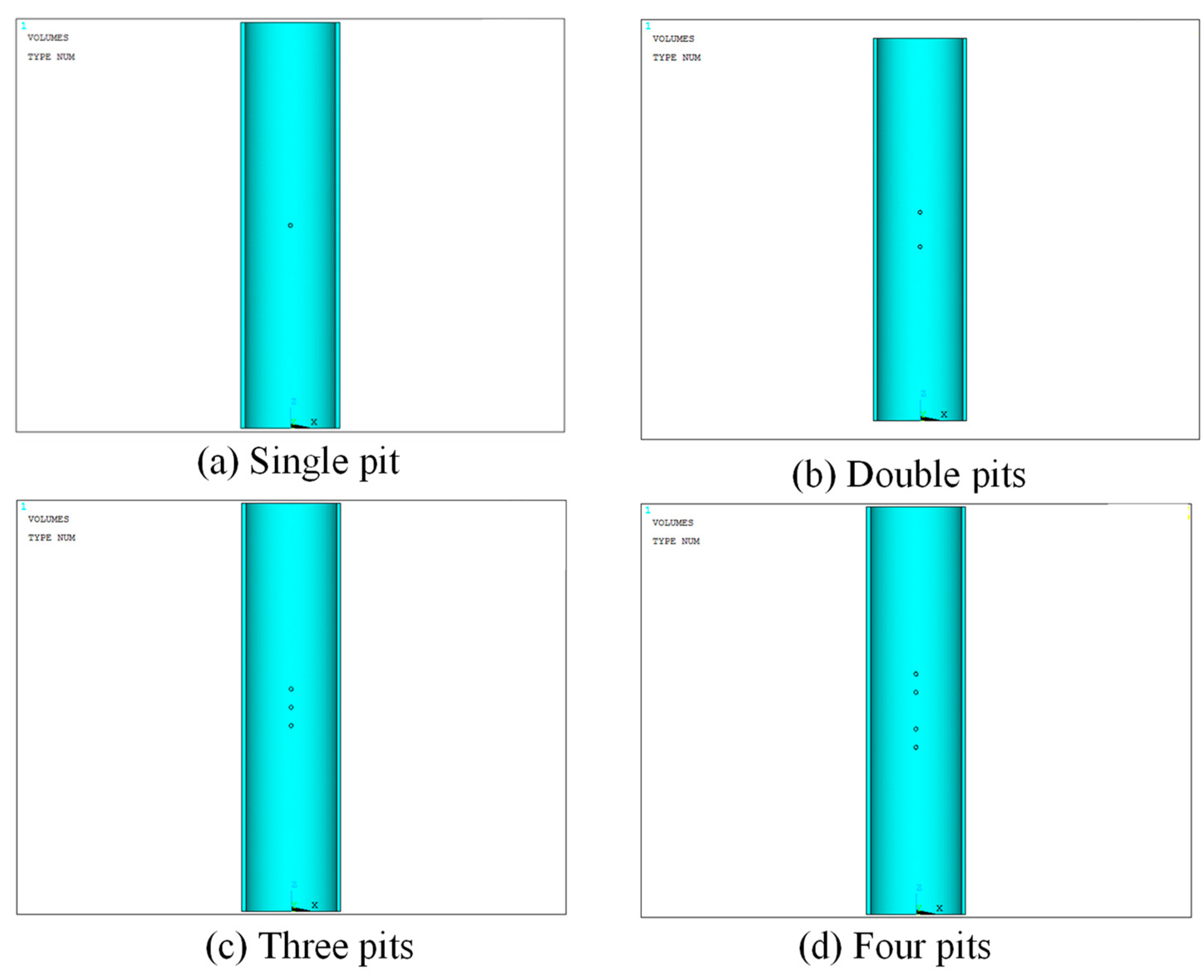
3.1.1. Finite Element Model

P110 casing is used in this model, parameters of which are presented in Table 1.
The FEM model is shown in Figure 3 and Figure 4 when the meshing is performed, the uniform internal pressure is applied and end DOF (degree of freedom) is constrained.

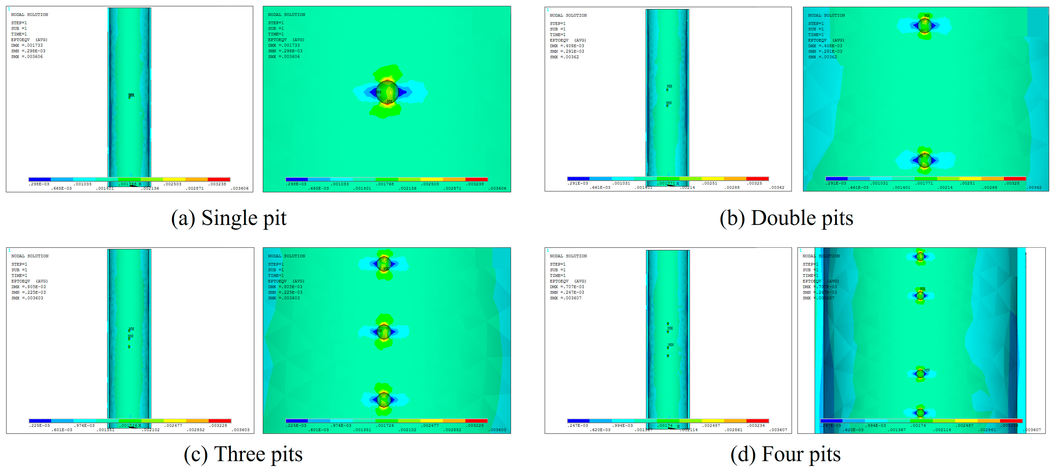
3.1.2. Calculation Results and Analysis

  • The effect of pitting corrosion depth
Table 2 is the calculation of fracture pressure of casing with different pit depth when casing is subjected to internal pressure. Figure 5 shows the trend of fracture pressure with different pitting corrosion depth. It can be seen that with the development of corrosion, depth of pitting corrosion is getting deeper, remaining wall thickness becomes thinner and fracture pressure shows a tendency toward increasing first and then decreasing. The main reason is that, for pitting corrosion, when pit depth is shallow, the stress is concentrated locally in the pitting corrosion area, so that casing tends to crack at the pit. When the pitting depth increases (2–7 mm), the total corrosion area under internal pressure also increases accordingly, making the stress concentration get some relief, thus fracture pressure increases. When pitting depth further increases to 8 mm, since the remaining casing wall thickness is only 2.36 mm, residual strength of casing decreases rapidly, thus cause the fracture pressure to drop.
Figure 6 shows the equivalent stress and strain distribution of casing with different depths (2 mm, 4 mm, 6 mm and 8 mm) of pitting corrosion when casing is subjected to fracture pressure. As can be seen from the figure, the maximum stress and strain position are above and below the pitting, which is, diverging outward along the axial direction of the casing. While the left and right sides of the pitting cavity come out low stress and strain zones. This is mainly related to the force state of the casing. When the pitting depth is 2 mm and 8 mm, the shallow green stress zone of the casing is smaller than the area under the other two conditions, which is consistent with the results in Table 2.
  • The effect of pits number
In actual situation, when pitting corrosion occurs on casing, it will first start from a local area. Then, the place where pitting corrosion occurs is more and more. This may cause casing damage. The number and density of pits are necessarily related to anti-cracking performance of casing. In this section, a finite element model with a different number of pits is established in Figure 7, and the influence of the number of pits on casing strength is calculated and analyzed.
Taking pit depth of 5 mm as an example, with number of pits being 1, 2, 3 and 4, respectively; the fracture pressure was calculated and shown in Table 3. It can be seen that the small increase in the number of pits does not significantly change the fracture pressure of casing, but with increase in number, the fracture pressure decreases generally.
Figure 8 indicates the Mises stress and strain distribution of casing under fracture pressure with different number of pits. As can be seen from the figure, when casing with a number of corrosion pits under the inner pressure, each pit will appear a certain degree of stress concentration. However, a pit that shows the greatest Mises stress will be cracked firstly. When the internal pressure continues to increase, the remaining pits will be cracked successively. It is envisioned that if the number of pits is large enough, the stress concentration zone of adjacent pitting corrosion will intersect, and when such a situation occurs, the casing tends to be more prone to fracture. Therefore, in general, the greater the number of corrosion pits, the lower the compressive strength of the casing.

3.2. Strength Analysis of Casing with Strip Corrosion

3.2.1. Finite Element Model of Strip Corrosion

The model uses P110 casing, parameters of which are presented in Table 1. Take the casing finite element model with 1 m length: because the casing has a symmetrical cross-section, so the finite element model can be simplified as a symmetric model. The middle of strip corrosion is rectangular, ends are round, the overall appearance is strip and the finite element model is shown in Figure 9. Strip corrosion depth was selected with different values. The residual wall thickness is the total wall thickness minus the corrosion depth. Define the cell type and divide the grid, as shown in Figure 10. The uniform internal pressure is applied, and when the internal pressure is 50 MPa, the loading figure is shown in Figure 11.

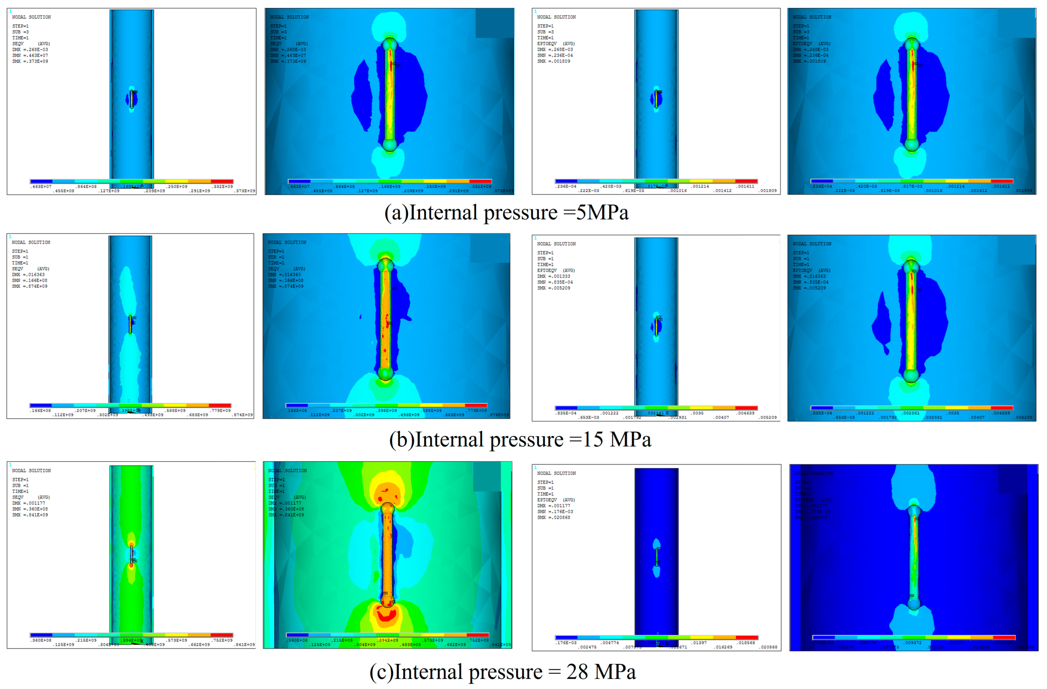
3.2.2. Calculation Results and Analysis

Take strip corrosion depth is 5 mm and internal pressure value is 5, 15 and 28 MPa, respectively, for example. Figure 12 is the maximum equivalent stress and strain distribution of the casing with strip corrosion under different internal pressure. As shown in the figure, the maximum equivalent stress and strain of the casing increase with an increase in internal pressure. The central position (red stress region) and the outer ends of the strip corrosion have the highest equivalent stress and second maximum stress positions. Hence, the region with the highest stress is mostly distributed alongside the long axis of the strip corrosion (specimen’s axial direction). The short axis of the strip corrosion has no stress concentration and appears as a low stress region. The location of the maximum strain is near the center of the strip corrosion, and there is no strain concentration in areas far away from the strip corrosion.
  • The effect of strip corrosion depth.
Table 4 is the calculation of the bursting pressure of the casing with different strip corrosion depth when subjected to internal pressure.
Figure 13 shows the relationship between the fracture pressure and the corrosion depth when the casing with strip corrosion is subjected to internal pressure. Figure 14 is Missile stress and strain distribution of casing with different strip corrosion depth under fracture pressure. It can be seen that with the development of corrosion and corrosion depth getting deeper, the remaining wall thickness becoming thinner, fracture pressure gets lower, and the fracture pressure reduce speed is faster. Initially, a reduction of 1 mm in wall thickness resulted in a fracture pressure decrease of approximately 0.02 MPa. However, as wall thickness continued to decrease, each 1 mm reduction resulted in a fracture pressure decrease of 4 MPa or more.
  • Effect of axial length of strip corrosion.
In general, the effect of the strip corrosion length and depth on the failure pressure of the casing is not the same. In order to compare the influence of these two factors on the failure pressure, the effect of the axial length of the strip corrosion on the failure pressure is also calculated in this chapter.
It can be seen in Figure 13 and Figure 15 that the effect of the length and depth of strip corrosion on the residual strength of the casing is not exactly the same. The failure pressure of the casing was decreasing when the length of the band corrosion was increased from 90 mm to 270 mm. However, the increase in corrosion length has little effect on the fracture pressure of the casing compared to the depth of the band corrosion. It can be seen that the effect of the depth of band corrosion on the fracture pressure is greater than the effect of the corrosion length.

4. Conclusions

Salt cavern compressed air energy storage technology has an important impact in effectively solving the problems of renewable energy volatility and energy utilization efficiency, and furthermore, promoting energy transformation and regional economic development. As the intermediate link of this system, the wellbore assumes the bridge between the surface equipment and the underground salt cavern space, and the casing is the core component of the wellbore. From the above-mentioned study of casing corrosion, the following conclusions can be drawn:
(1) The pitting corrosion depth is closely related to the fracture pressure and collapse pressure. When the pitting corrosion depth is small, the thickness reduction of the wall caused by the pitting corrosion has a minimum effect on fracture and collapse pressure. As pitting corrosion depth increased, the influence of corrosion depth increased.
(2) The greater the number of corrosion pits, the lower the compressive strength of the casing and the casing tends to be more prone to fracture.
(3) The area with large stress is mainly distributed along the long axis of the strip corrosion. In the short axis of the strip corrosion there is no stress concentration and appears as a low stress region.
(4) The increase in the length of the strip corrosion has little effect on the failure pressure of the casing. The effect of strip corrosion depth on failure pressure is greater than the effect of corrosion length.

Author Contributions

Conceptualization, W.J.; Methodology, J.W. and W.J.; Software, W.J.; Writing—original draft, Y.H.; Writing—review & editing, Y.G.; Visualization, J.L. All authors have read and agreed to the published version of the manuscript.

Funding

The authors would gratefully like to acknowledge the financial support from the Scientific Research and Technology Development Project of China Energy Engineering Corporation Limited (No. CEEC-KJZX-04).

Data Availability Statement

All data details are in the paper, and there is no additional data to share.

Conflicts of Interest

The authors declared no potential conflict of interest with respect to the research, authorship, and/or publication of this article.

References

  1. Alirahmi, S.M.; Razmi, A.R.; Arabkoohsar, A. Comprehensive assessment and multi-objective optimization of a green concept based on a combination of hydrogen and compressed air energy storage (CAES) systems. Renew. Sustain. Energy Rev. 2021, 142, 110850. [Google Scholar] [CrossRef]
  2. Chen, L.; Zheng, T.; Mei, S.; Xue, X.; Liu, B.; Lu, Q. Review and prospect of compressed air energy storage system. J. Mod. Power Syst. Clean Energy 2016, 4, 529–541. [Google Scholar] [CrossRef] [Green Version]
  3. Pottie, D.; Cardenas, B.; Garvey, S.; Rouse, J.; Hough, E.; Bagdanavicius, A.; Barbour, E. Comparative Analysis of Isochoric and Isobaric Adiabatic Compressed Air Energy Storage. Energies 2023, 16, 2646. [Google Scholar] [CrossRef]
  4. Li, N.; Zhao, Y.; Wang, T.; Yang, C. Trends Observation: Strategy and Development of lnternational Salt Cavern Energy Storage Research. Bull. Chin. Acad. Sci. 2021, 36, 1248–1252. [Google Scholar]
  5. Li, J.; Wan, J.; Liu, H.; Jurado, M.J.; He, Y.; Yuan, G.; Xia, Y. Stability Analysis of a Typical Salt Cavern Gas Storage in the Jintan Area of China. Energies 2022, 15, 4167. [Google Scholar] [CrossRef]
  6. Wang, G.; Zhang, X.; Li, Z.; Li, Q.; Han, Y.; Xue, X.; Mei, S. Thermodynamics analysis of salt cavern for compressed air energy storage system. Renew. Energy Resour. 2019, 37, 618–624. [Google Scholar]
  7. Ban, F.; Yuan, G.; Wan, J.; Peng, T. The optimum interwell distance analysis of two-well-horizontal salt cavern construction. Energy Sources Part A Recover. Util. Environ. Eff. 2021, 43, 3082–3100. [Google Scholar] [CrossRef]
  8. Peng, T.; Wan, J.; Liu, W.; Li, J.; Xia, Y.; Yuan, G.; Jurado, M.J.; Fu, P.; He, Y.; Liu, H. Choice of hydrogen energy storage in salt caverns and horizontal cavern construction technology. J. Energy Storage 2023, 60, 106489. [Google Scholar] [CrossRef]
  9. Wan, J.; Peng, T.; Yuan, G.; Ban, F.; Jurado, M.J.; Xia, Y. Influence of tubing/oil-blanket lifting on construction and geometries of two-well-horizontal salt caverns. Tunn. Undergr. Space Technol. 2020, 108, 103688. [Google Scholar] [CrossRef]
  10. Sun, X.; Gui, Z.; Zhang, X.; Li, Y.; Li, X.; Xu, Y.; Wang, W.; Zhou, J.; Chen, H. Research Progress on Compressed Air Energy Storage Coupled with Renewable Energy. Proc. CSEE 2023, 43, 1–20. [Google Scholar]
  11. Li, J.; Wan, J.; Wang, T.; Yuan, G.; Jurado, M.J.; He, Q. Leakage simulation and acoustic characteristics based on acoustic logging by ultrasonic detection. Adv. Geo-Energy Res. 2022, 6, 181–191. [Google Scholar] [CrossRef]
  12. Wan, J.; Peng, T.; Shen, R.; Jurado, M.J. Numerical model and program development of TWH salt cavern construction for UGS. J. Pet. Sci. Eng. 2019, 179, 930–940. [Google Scholar] [CrossRef] [Green Version]
  13. Wan, J.; Peng, T.; Jurado, M.J.; Shen, R.; Yuan, G.; Ban, F. The influence of the water injection method on two-well-horizontal salt cavern construction. J. Pet. Sci. Eng. 2020, 184, 106560. [Google Scholar] [CrossRef]
  14. Li, J.; Wan, J.; Liu, H.; Yi, X.; He, Y.; Chen, K.; Zhao, X. Numerical Study of Casing Microleakage Flow Field Sensitivity and Acoustic Field Characteristics. Materials 2023, 16, 386. [Google Scholar] [CrossRef] [PubMed]
  15. El Wanees, S.A.; Radwan, A.B.; Alsharif, M.; El Haleem, S.A. Initiation and inhibition of pitting corrosion on reinforcing steel under natural corrosion conditions. Mater. Chem. Phys. 2017, 190, 79–95. [Google Scholar] [CrossRef]
  16. Dong, S.; Fang, T.; Wan, J.; Hu, X.; Li, J.; Liu, H.; Li, D.; Qiao, S. Study on the Effect of the Water Injection Rate on the Cavern Leaching Strings of Salt Cavern Gas Storages. Energies 2023, 16, 344. [Google Scholar] [CrossRef]
  17. Shi, X.; Chen, P.; Xu, J.; Jiang, Z.; Nie, R.; Qing, X.; Wang, D.; Zhao, D. Analysis on Residual Strength of CO2 Tubercular Corrosion for Casings of Oil/Gas Wells. Nat. Gas Ind. 2006, 26, 95–97. [Google Scholar]
  18. Che, Z.; Zhang, Z.; Chen, S. Analysis on the influence of corrosion on casing strength in acidic gas field development. Oil Drill. Prod. Technol. 2012, 34, 114–118. [Google Scholar]
  19. Wang, M.; Zhang, Z.; Zeng, D.; Shi, T.; Shao, L. An experimental study on casing corrosion in a high-H_2S gas field. Nat. Gas Ind. 2011, 31, 85–87+140–141. [Google Scholar]
  20. Nabipour, A.; Joodi, B.; Sarmadivaleh, M. Finite Element Simulation of Downhole Stresses in Deep Gas Wells Cements. In Proceedings of the SPE Deep Gas Conference and Exhibition, Manama, Bahrain, 24–26 January 2010. [Google Scholar]
  21. Zhu, X.; Luo, S. The Regularization of Casing Corrosion Defects and Collapse Strength Analysis. Sci. Technol. Eng. 2017, 17, 193–198. [Google Scholar]
  22. Lian, Z.; Luo, Z.; Yu, H.; Liu, Y.; He, Y. Strength assessment of casing with corrosion pit defects. J. Southwest Pet. Univ. (Nat. Sci. Ed.) 2018, 40, 159–168. [Google Scholar]
  23. Huang, X.; Mihsein, M.; Kibble, K.; Hall, R. Collapse strength analysis of casing design using finite element method. Int. J. Press. Vessel. Pip. 2000, 77, 359–367. [Google Scholar] [CrossRef]
Figure 2. Mechanical model of thick-walled cylinder.
Energies 16 05362 g002
Figure 3. Mesh generation.
Energies 16 05362 g003
Figure 4. Load even internal pressure and constraints.
Energies 16 05362 g004
Figure 5. The relationship between fracture pressure and pitting corrosion depth when casing is under internal pressure.
Energies 16 05362 g005
Figure 6. Missile stress and strain distribution of casing with different pitting corrosion depth under fracture pressure.
Energies 16 05362 g006
Figure 7. Finite element model with pittings.
Energies 16 05362 g007
Figure 8. Mises stress and strain distribution of casing under fracture pressure with different number of corrosion pits.
Energies 16 05362 g008
Figure 9. Finite element model of casing with strip corrosion.
Energies 16 05362 g009
Figure 10. Mesh generation of casing with strip corrosion.
Energies 16 05362 g010
Figure 11. Loading uniform internal pressure on casing with strip corrosion.
Energies 16 05362 g011
Figure 12. Mises stress and strain distribution of casing under different internal pressures.
Energies 16 05362 g012
Figure 13. The relationship between fracture pressure and corrosion depth of casing with strip corrosion.
Energies 16 05362 g013
Figure 14. Missile stress and strain distribution of casing with different strip corrosion depth under fracture pressure.
Energies 16 05362 g014
Figure 15. The relationship between fracture pressure and strip corrosion length of casing with strip corrosion.
Energies 16 05362 g015
Table 1. Casing model parameters.
Diameter
(mm)
Wall Thickness
(mm)
Elastic Modulus
(GPa)
Poisson RatioYield Limit
(MPa)
244.4810.362060.3689
Table 2. The fracture pressure of casing with different pitting corrosion depth.
Pitting Corrosion Depth
(mm)
Residual Wall Thickness (mm)Fracturing Pressure (MPa)
28.3618.5
37.3621.6
46.3622.54
55.3621.70
64.3622.2
73.3624.37
82.3621.45
Table 3. The fracture pressure of casing with different number of pits (5 mm).
Number of PitsFracture Pressure (MPa)
121.70
221.15
321.54
420.98
Table 4. Fracture pressure value of casing with different strip corrosion depth.
Corrosion Pitting Depth (mm)Residual Wall Thickness (mm)Fracture Pressure (MPa)
28.3630.52
37.3630.5
46.3629.12
55.3628
64.3625.28
73.3623.8
82.3619.98
Disclaimer/Publisher’s Note: The statements, opinions and data contained in all publications are solely those of the individual author(s) and contributor(s) and not of MDPI and/or the editor(s). MDPI and/or the editor(s) disclaim responsibility for any injury to people or property resulting from any ideas, methods, instructions or products referred to in the content.

