Article

Experimental and Numerical Studies on a Single Coherent Blade of a Vertical Axis Carousel Wind Rotor

Department of Machine Design and Composite Structures, Faculty of Mechanical Engineering, Cracow University of Technology, al. Jana Pawła II 37, 31-864 Krakow, Poland
*
Author to whom correspondence should be addressed.
Energies 2023, 16(14), 5532; https://doi.org/10.3390/en16145532
Submission received: 19 June 2023 / Revised: 12 July 2023 / Accepted: 19 July 2023 / Published: 21 July 2023
(This article belongs to the Section J1: Heat and Mass Transfer)

Abstract

:
This article presents the results of experimental and numerical studies on a single coherent rotor blade. The blade was designed for a vertical-axis wind turbine rotor with a self-adjusting system and planetary blade rotation. The experimental tests of the full-scale blade model were conducted in a wind tunnel. A computational fluid dynamics (CFD) analysis of the blade’s cross section was then carried out, including the boundary conditions corresponding to those adopted in the wind tunnel. The main objective of the study was to determine the aerodynamic forces and aerodynamic moment for the proposed single coherent cross-section of the blade for the carousel wind rotor. Based on the obtained results and under some additional assumptions, the driving torque of the wind rotor was determined. The obtained results indicated the possibility of using the proposed blade cross-section in the construction of a carousel wind rotor.

1. Introduction

Vertical-axis wind turbines (VAWTs) are design solutions based mainly on three basic rotors, which are the Darrieus wind rotor, the Savonius rotor and the H-type rotor [1,2,3], as presented in Figure 1. Vertical-axis wind turbines are much simpler to construct and less expensive to operate than horizontal-axis wind turbines (HAWTs). However, they are not very popular, mainly due to their low rotational speed and low efficiency [4,5].
The Darrieus rotor consists at least of two thin, semicircular curved blades that rotate in a vertical plane [6]. The studies presented by Mohan Kumar et al. [7] and Gorelov et al. [8] provide a comprehensive overview on the development of these wind turbines from early to current applications. Two more publications on the practical applications of the Darrieus turbine can be cited here. These are the study by Islam et al. [9] and the work by Gharib-Yosry et al. [10], where the authors presented the operation of the Darrieus turbine rotor as a wind or hydro microgenerator.
The Darrieus rotor is not provided with a wind orientation system, but due to its propelling torque of practically zero, it is necessary to use an auxiliary drive designed for start-up [11,12]. This can be an electric motor or an assist rotor such as the Savonius rotor, which is a rotor with a simple design and a high starting torque. It comprises two blades that are aligned with each other so that they form an “S” shape in the cross-section of the rotor. The gap obtained between the blades reaches a dimension in the range of 0.1 to 0.15 of the single rotor blade diameter [13]. To improve the coefficient of power and to obtain the uniform coefficient of the static torque, the conventional Savonius or modified forms of this rotor have been investigated. Among the studies aiming to achieve these objectives are those conducted by Kamoji et al. [14] and Moutsoglou et al. [15].
Several modified turbine designs can be obtained by combining the advantages in design and aerodynamic features of two different turbines (like a simple design or no need to use the self-adjusting system), while eliminating their disadvantages (like low efficiency or high driving torque fluctuations). Examples of such designs include the following: the TURBY turbine presented by Bussel et al. [16], the H-Darrieus turbine [17] or the spiral wind turbine, like the one presented by Nader et al. [18]. The quoted designs are wind rotors that ensure uniform operation independent of the wind direction and that emit low noise levels during operation.
An alternative to the above design solutions is the carousel wind rotor described in publications [19,20] and presented in Figure 2. The rotor comprises at least three blades connected to the drive shaft by means of a gear. Each of the blades requires proper balancing so that the resistance on the bearings during operation is as low as possible. This rotor has a vertical axis of rotation and planetary blade motion.
The rotor blades are aligned on vertical rotor pivots and are coupled by gears with a gear ratio of 1:2 to a sleeve coaxial using the rotor axis. This causes the blades to rotate at half the speed and in the opposite direction to the rotor rotation. The angular position of the blades relative to the wind direction is determined by the self-adjusting system [20]. This system is connected directly to the worm gear sleeve located under the rotor housing and then coupled to the planetary gear.
The operating principle of the carousel wind rotor implies that the blade surfaces work alternatively, every second revolution of the rotor. Therefore, the cross-section of the blades has point symmetry. A large propelling torque, caused mainly by drag force and to a lesser extent, by lift force, is typical for the carousel wind rotor. The other typical feature of the rotor is a low turbine speed during operation. The rotor reaches and keeps its maximum speed despite increasing the wind load, which follows from the kinematics.
One of the main design problems related to the vertical-axis carousel wind rotor is the selection of an appropriate cross section for the blades. Our research focuses on verifying the feasibility of the proposed single coherent blade section in this type of rotor.

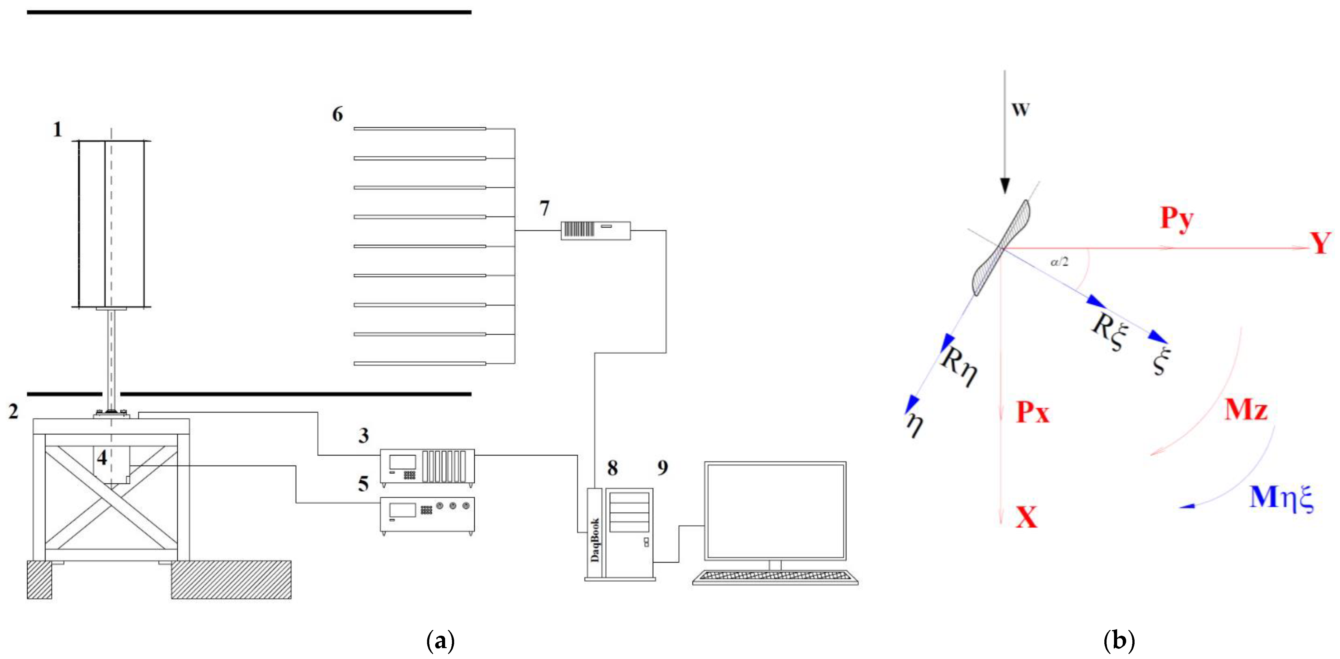
1.1. Movement of the Single Blade of the Carousel Wind Rotor

The shape of the blades and the nature of the blade movement relative to the rotor’s axis of rotation are of major significance in the search for the most advantageous design solutions for the carousel wind rotor. In this study, we focused on the single coherent cross-section of the blade. The planetary movement of the blades is characteristic of the carousel wind rotor. The movement referred to the single blade considered in this study is shown in Figure 3. The x, y coordinates refer to the global coordinate system related to the rotor. Meanwhile, the η, ξ coordinates refer to the moving coordinate system related to the blade. The planetary motion of a single blade, starting from position A1 up to position A8, is shown in Figure 3.
The action of wind W on the blade surface causes it to rotate around the rotor axis. An appropriate planetary gear ratio enables favorable blade positions to be obtained during rotor operation. Position A5 is the most advantageous for easy rotor starting when β = 0. The effective operation of the blade is achieved when the blade passes from position A3 to position A7. In turn, when the blade passes from position A7 to position A3, low aerodynamic drag occurs despite the rotor blade passing upwind. As a result of the blade’s planetary motion, a single cycle of the blade’s transition from position A1 back to position A1 results in a 180° rotation of the cross-section. This means that the blade returns to the starting position A1 every second cycle.

1.2. Procedure for Calculating Propelling Torque

According to Figure 3, the blade of the wind rotor is subjected to forces Rξ, Rη and torque Mηξ. Therefore, a general formula for the total rotor-propelling torque generated by one blade M1(αs), as a function of the angle of the rotor rotation α(αs), can be written as follows:
M 1 ( α s ) = R η cos α 2 + R ξ sin α 2 R + M η ξ ,
where R is the radius of the rotor equal to 1.5 m.
The total torque for the three rotor blades MIII(αs), relative to the coordinate system η, ξ and for V0 = 0, is the sum of the torques of each of the rotor blades M1(αs), M2(αs) and M3(αs) as a function of the angle of the rotor rotation α(αs), as given by the following equation:
M I I I ( α s ) = M 1 ( α s ) + M 2 ( α s ) + M 3 ( α s )

2. Materials and Methods

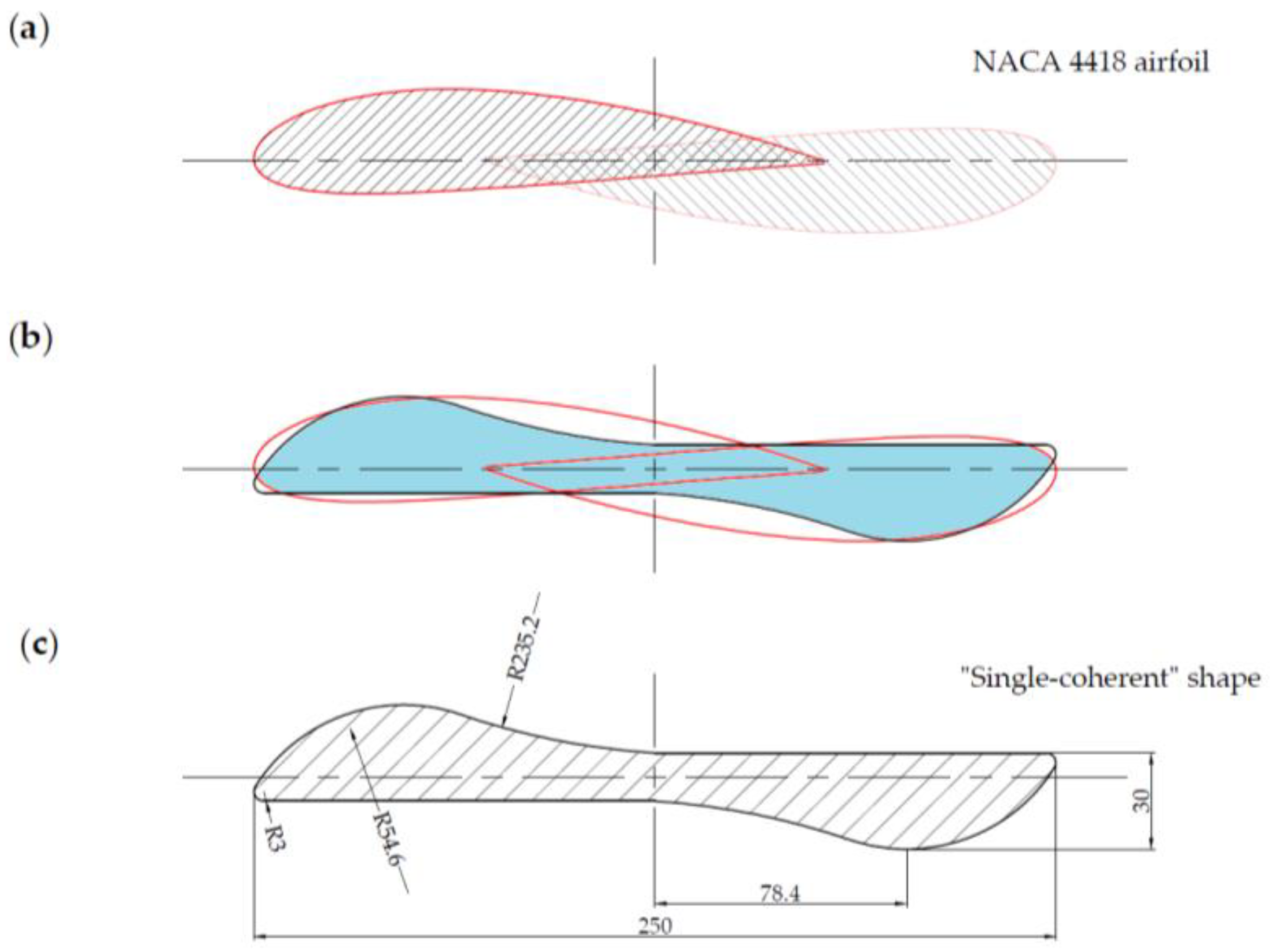
2.1. Cross-Section of the Carousel Wind Rotor Blade

According to the research results of Rogowski et al. [21], as well by as comparing these results to information provided in the Wind Tunnel Data for NACA 4418 Series Airfoil [22], the NACA 4418 airfoil was found to be the most preferable airfoil for application in vertical-axis wind turbines. However, concerning the blade motion of the carousel wind rotor, described in the previous section, it was concluded that the cross-section for such a rotor must have point symmetry, as shown in Figure 4a. Therefore, the blade section resulting from the connection of two identical airfoils was adopted, as shown in Figure 4b. Finally, the resulting single coherent cross-section of the blade was proposed, as presented in Figure 4c.
Due to the dimensions of the wind tunnel working section, the overall dimensions of the tested blade were adopted as summarized in Table 1:
For the assumed dimensions of the tested blade, the geometric scale kD was 1/1. Therefore, the determination of other similarity criteria was not required.
An additional advantage of the single coherent blade is the impact of the aerodynamic effect on the driving torque schematically illustrated in Figure 5. Concerning a flat blade over the entire surface, the aerodynamic force Ns acts on arm r1. In turn, for the considered single coherent shape of the blade, an additional pair of forces Na × r occurs. This results in an advantageous shift in the resultant force N to the larger arm r2 with respect to the rotor rotation axis O. The driving torque is N × r2 > Ns × r1, which provides an increase in the power of the turbine rotor.

2.2. Wind Tunnel Test Conditions

The experimental tests were conducted in the wind tunnel of the Wind Engineering Laboratory at the Cracow University of Technology. This is a wind tunnel of a mixed circuit: closed or open. In the case of our study, the tunnel operated in a closed circuit. The air flow was forced by a fan placed behind the working section, which sucked in the air. The dimensions of the working section are as follows: width equal to 2.20 m, height from 1.40 to 1.60 m, and length of 10 m, including 2 m for the measuring section [23]. The basic characteristics of the measurement parameters are shown in Table 2.
The tested blade was attached via the supporting element to an aerodynamic balance at a height of 300 mm above the level of the measuring table. The supporting element was shielded by a fairing to prevent an increase in the wind load, as shown in Figure 6a.
The turbulence intensities IW(hw) were calculated according to the following formula:
I W ( h w ) = σ ( h w ) W r e f ( h w )
where Wref( h w ) is the mean value of the wind speed, σ( h w ) is the standard deviation of the wind speed and h w is the height of the wind profile.
The formation of the wind profile took place in the first part of the wind tunnel working section, over a length of 6 m, using a turbulence grid and spires with appropriate geometry and spacing. The wind tunnel was equipped with 0.2 m high barriers and 1 m high spires to force turbulent air flow. The resulting turbulence level was about 8%.
The wind speed measurement was carried out using a set of pressure sensors. The mean wind speed was calculated based on the mean speed value of the wind profile. The wind profile was determined for heights in the range of 0 to 900 mm for each of the cases analyzed. The wind profile for average values is shown in Figure 6b. Considering the height and position of the tested blade, the mean value of the wind speed Wref = 12.5 m/s was accepted for further analyses. The pressure sensors were placed in a vertical plane on the left side of the tested blade, as shown in Figure 6a. The measurement time was assumed to be 10 seconds, during which, 6000 samples were collected.
For the tested blade, the aerodynamic forces Px, Py and the aerodynamic torque Mxy were measured using the five-component aerodynamic balance based on the electric resistance strain gauges [24]. The orientation of the fixed coordinate system x, y, z was as follows: x—along wind direction; y—across wind direction; z—vertical direction.
The scheme of the applied measuring system is presented in Figure 7a. The tested blade 1 was mounted on a five-component aerodynamic balance 2. The balance was wired to an amplifier module with a data acquisition system in order to 3 collect the aerodynamic force values. The aerodynamic balance enabled the determination of components Px and Py of the aerodynamic forces, as well as the torque Mxy with respect to the coordinate system, which is shown in Figure 7b. The change in the wind attack angle was carried out by a turntable with a stepper motor 4, which was used to change the angular position of the model relative to the x, y plane and thus change the wind attack angle. The rotation of the stepper motor was controlled by a motor step control system 5. The turntable is a part of the aerodynamic balance, and its axis of rotation coincides with the axis of the balance. The wind speed was obtained based on the pressure measurements provided by sensors 6 located in the x, z plane, which were connected to the pressure scanner 7. Aerodynamic forces and wind speed measurements were recorded using a DaqBook card 8 on a PC 9. Similar problems, including research in a wind tunnel, were described in publications [25,26,27,28,29,30,31]. In turn, the authors of publication [32] conducted experimental studies in a wind tunnel to analyze the dynamic response of a horizontal axis wind turbine depending on the number of blades.

2.3. CFD Simulation

The analysis of the air flow around the turbine blades was carried out using the ANSYS/Fluent Release 2020 R2 software. First, the k—ω SST turbulence model was adopted. Then, discrete models were prepared, including proper boundary layer modeling and mesh validation. Afterwards, the boundary conditions were defined. Finally, airflow simulations were carried out for the analyzed single coherent blade in the range of the wind attack angle from 0° to 180° with increments of 10°.

2.3.1. Governing Equations

The ANSYS Fluent solved the mass and momentum conservation equations for all the analyzed flows. The mass conservation equation in its general form is given by Equation (4), while the momentum conservation equation is given by Equation (5). An additional energy conservation equation, Equation (6), is solved for flows that take into account heat transfer or the compressibility of the fluid [33]. In the analyses presented in this paper, the energy equation was not included.
ρ t + · ρ v = 0
t ρ v + v · ρ v = p + · τ ̿ + F b
t ρ e t + · v ρ e t + p = · k T + τ ̿ · v + S g
where ρ is the fluid density, Nabla operator ∇ stands for the partial derivative with respect to all directions in the coordinate system, v is the velocity vector, p stands for static pressure, τ ̿ is the stress tensor, F b stands for the body force per unit volume, et is the total energy in the system, k is the thermal conductivity, T stands for temperature, and Sg is the heat of the chemical reaction and any defined volumetric heat sources.

2.3.2. Turbulence Model

The Shear Stress Transport (k—ω SST) turbulence Menter model [34,35] was adopted for the analysis of the air flow around the blade. This is a two-equation eddy–viscosity model that is used for many aerodynamic applications [36,37,38]. The SST Menter model combines the k—ω Wilcox model [39] and standard k—ε model [40]. A blending function is used to activate the k—ω model near the wall and the k—ε model in the free stream. This eliminates the problem with the k—ω model, which is sensitive to inlet free-stream turbulence properties. The use of the k—ω SST model ensures that the appropriate turbulence model is applied across the entire flow field. The two-equation k—ω SST model written in conservation form is given by the turbulence kinetic energy Equation (7) and the specific dissipation rate Equation (8).
( ρ k ) t + ( ρ u i k ) x j = τ i j u i x j β * ρ ω k + x j μ + σ * μ t k x j
ρ ω t + ρ u i ω x j = γ ν t τ i j ρ u i ω x j β ρ ω 2 + x j μ + σ μ t k x j + 2 1 F 1 ρ σ ω 2 1 ω k x j ω x j
where ρ is the air density, k is the specific turbulence kinetic energy, t is time, τij is the stress tensor, ui is the velocity vector, xj is the position vector, ω is the specific dissipation rate, β*, σ* are the closure coefficients in the turbulence kinetic energy equation, µ is the molecular viscosity, µt is the eddy viscosity, β, σ are the closure coefficients in the specific dissipation rate equation, and νt is the turbulent kinetic viscosity.
The Favre-averaged specific Reynolds stress and strain tensors are given by Equations (9) and (10). The turbulent eddy viscosity is computed using Equation (11).
τ i j = μ t 2 S i j 2 3 u k x k δ i j 2 3 ρ k δ i j
S i j = 1 2 u i x j + u j x i
μ t = ρ a 1 k m a x a 1 ω , Ω F 2
A constant ϕ is obtained from Equation (12). The constants ϕ1 and ϕ2 refer to the k—ω and k—ε models, whereas F1 is a blending function. The other auxiliary relations are given by Equations (13)–(16).
ϕ = F 1 ϕ 1 + 1 F 1 ϕ 2
F 1 = t a n h m i n m a x k β * ω d , 500 ν d 2 ω , 4 ρ σ ω 2 k C D k ω d 2 4
C D k ω = m a x 4 ρ σ ω 2 1 ω k x j ω x j , 10 20
F 2 = t a n h m a x k β * ω d , 500 ν d 2 ω 2
γ 1 = β 1 β * σ ω 1 κ 2 β * , γ 2 = β 2 β * σ ω 2 κ 2 β *
where d is the distance from the field point to the nearest wall. The constants used by Ansys Fluent [41] are as follows:, σω1 = 2.0, β1 = 0.075, σω2 = 1.168, β2 = 0.0828, β* = 0.09, κ = 0.41, and α1 = 0.31.

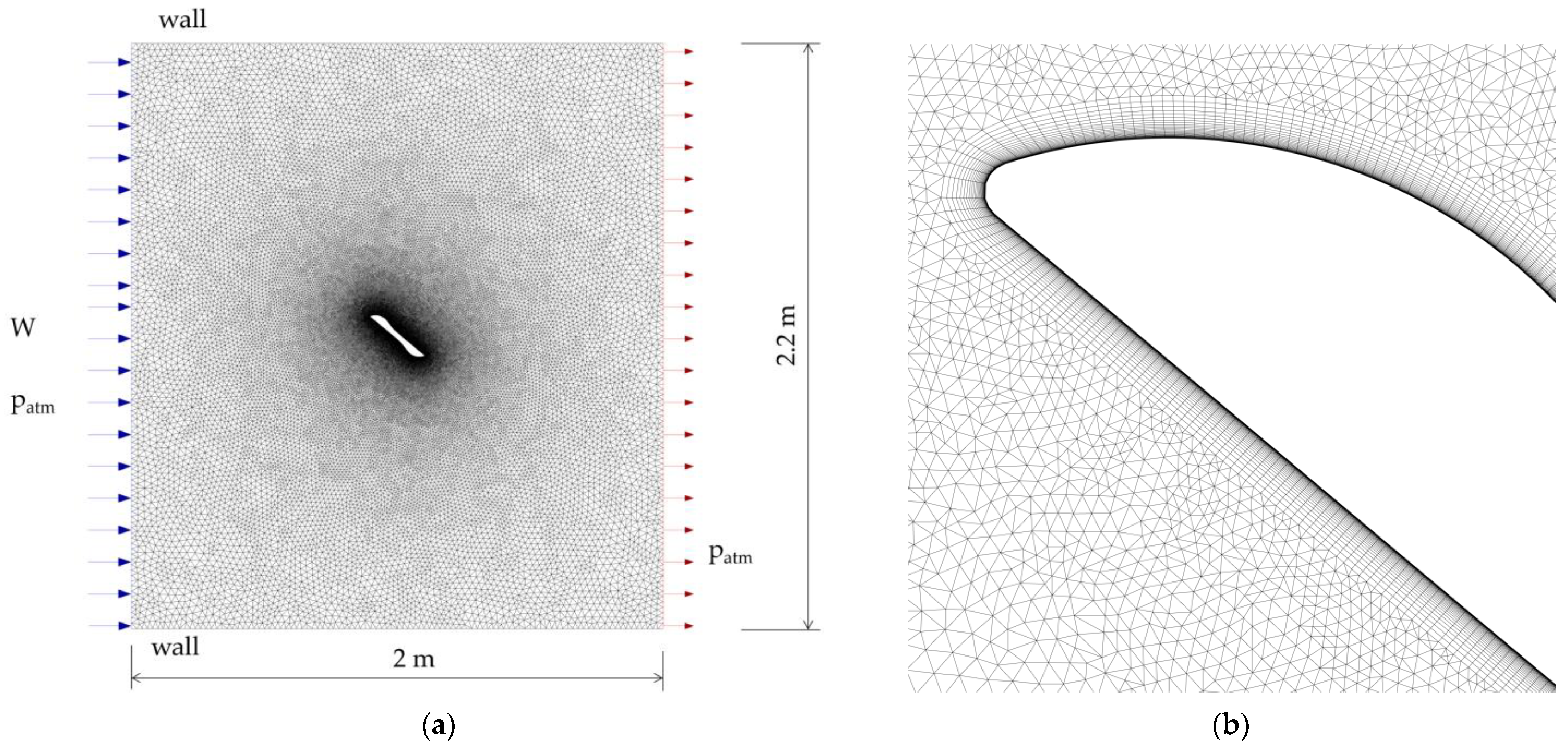
2.3.3. Discrete Models and Assumptions for CFD Analysis

The two-dimensional model is usually sufficient to analyze the airflow problems, for which the wind speed in front of the examined object has only one component and the effects occurring at the ends of the object have a minor impact [37,42,43]. Therefore, two-dimensional models of airflow around the blades were also adopted for the CDF analysis in this study. The dimensions of the computational domains corresponded to the dimensions of the wind tunnel test section. An example of a discrete model for the wind attack angle γ = 40° is shown in Figure 8. The mesh was generated using irregular elements. The mesh consisted of approximately 92,000 triangular elements within the free stream and approximately 15,400 quad elements within the inflation layer on the blade surface.
The viscous sublayer should be directly resolved since boundary layer separation can occur for the considered range of the wind attack angle. In Ansys Fluent, viscous enhanced wall treatment is provided when the nondimensional parameter y+ = 1; however, y+ < 4 or y+ < 5 is still acceptable as long as it is inside a viscous sublayer [41].
For all computed cases in this study, y+ < 1 was provided by adopting the following parameters in the inflation layer:
  • First layer height = 0.01 mm
  • Number of layers = 30
  • Growth rate = 1.15
The following assumptions were made for the CFD analyses:
  • Wind speed: W = 12.5 m/s was assumed as an average value from the wind profile
  • Air density: ρ = 1.16 kg/m3
  • Air viscosity: μ = 1.7894 × 10⁻⁵ kg/ms.
  • Averaged Reynolds number: Re = 8.1 × 10⁵
  • Turbulence intensity of 8% was set at the inlet and outlet
  • Hydraulic diameter was equal to 1 m
  • Pressure-based solver was adopted
  • The convergence of the numerical solution was obtained for both the mass and momentum residuals less than 10−3

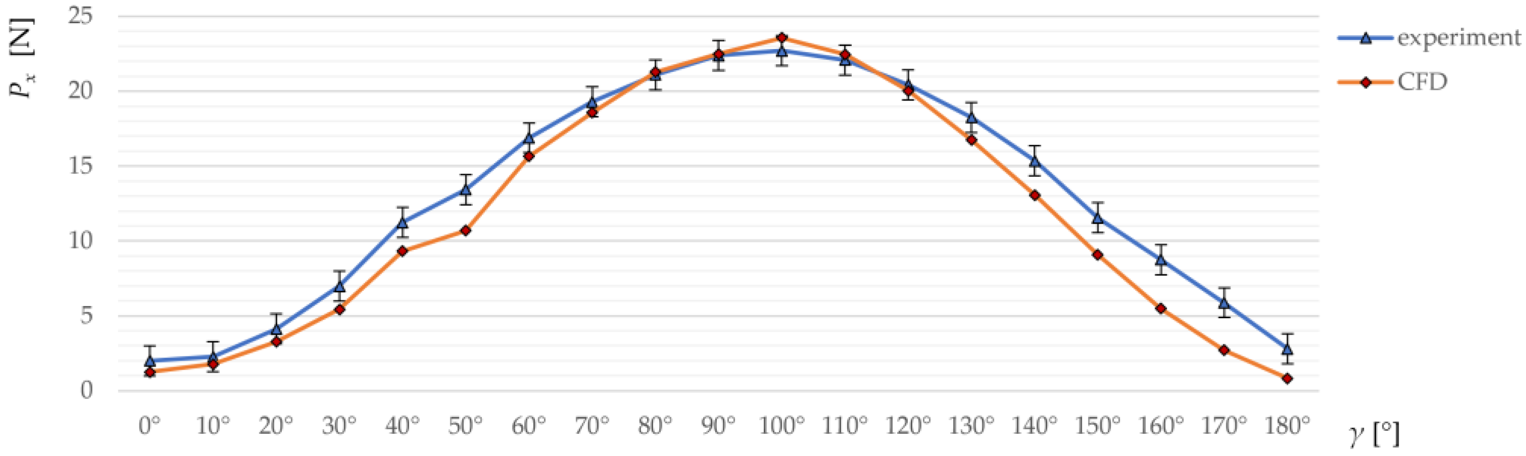
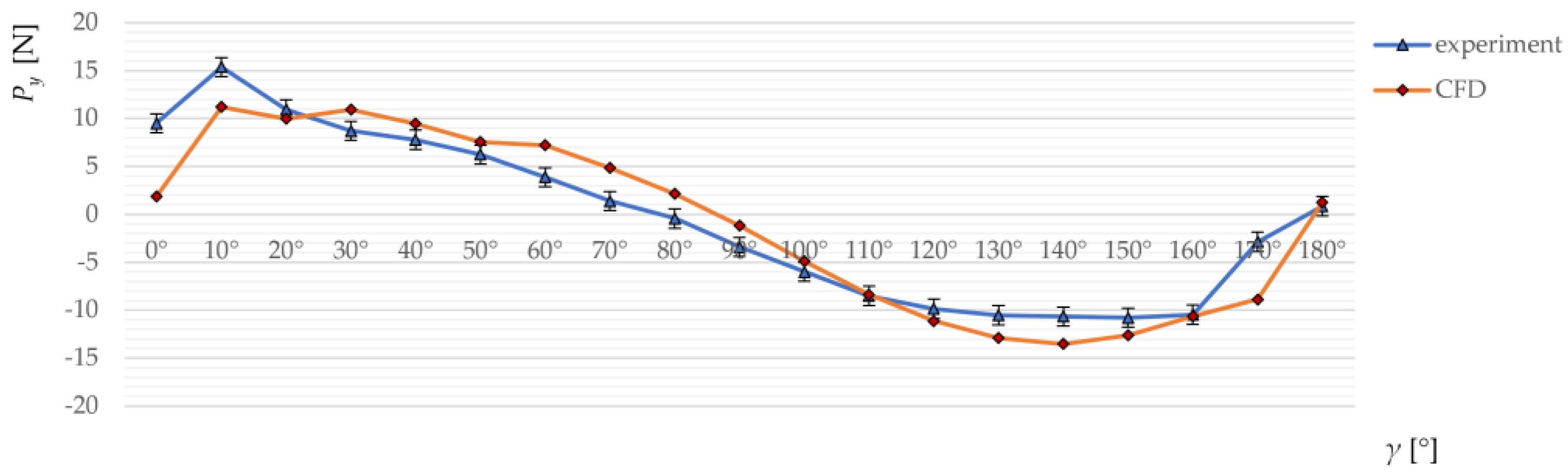
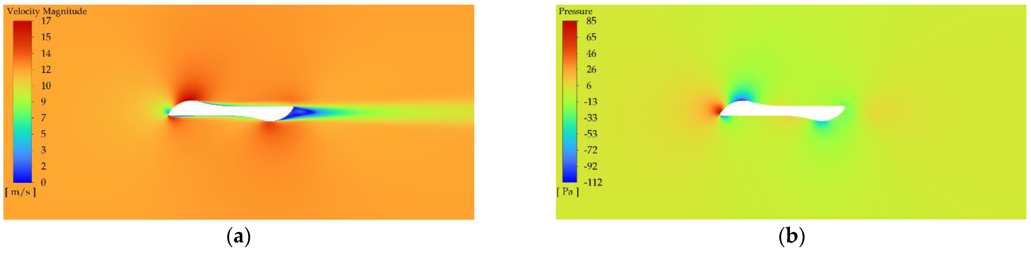
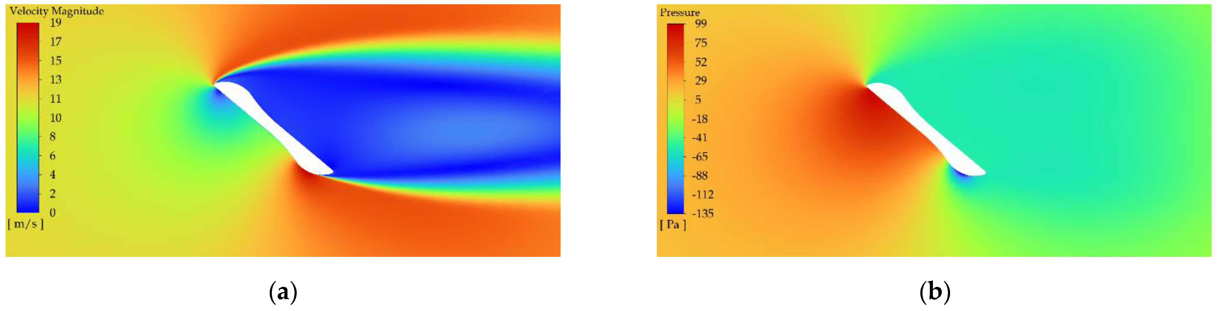
2.3.4. Validation of Numerical Solution

The accuracy of the numerical solution is typically verified by comparing the simulation results with the experimental data. On the other hand, the effect of the of the discrete model quality is tested by means of the mesh independence test based on the mesh refinement. The mesh validation was carried out for the discrete model considering the wind attack angle γ = 20°. The effect of the mesh refinement level on the aerodynamic forces Px and Py acting on the blade was checked. The mesh validation results are shown in Figure 9.
A mesh refinement level equal to 1 stands for coarse mesh, whereas levels 2–6 concern the increasing level of mesh refinement. Finally, a mesh refinement level of 5 was accepted for all the CFD analyses. The size of the discrete models ranged from about 110,000 to 120,000 finite elements, depending on the wind attack angle.

3. Results

The results of the experimental tests and CFD simulations concerning the aerodynamic forces and the aerodynamic torque acting on the single wind rotor blade depending on the wind attack angle γ are shown in Figure 10, Figure 11 and Figure 12. The aerodynamic drag Px is shown in Figure 10, whereas the results referring to the lift force Py are presented in Figure 11. In turn, the obtained aerodynamic torque Mxy is shown in Figure 12. The graphs include error bars reflecting the aerodynamic balance error, which was ±1 N for Px and Py and ±0.2 Nm. Some of the differences between the experimental and simulation results could be caused by not including surface roughness in the numerical model, adopting the two-dimensional model for CFD analysis, or accepting the average velocity from the wind profile and averaged turbulence intensity.
Considering the results for aerodynamic drag Px, it can be seen that, for a wind attack angle of 0°–90°, the drag increased significantly. The highest values of aerodynamic drag occurred in the angle range of 80°–120°. In contrast, the lowest values occurred in the angle ranges 0°–30° and 160°–180°. The maximum value in these angle ranges was about 5 N.
For the wind angle of 0°, the blade is aligned to the wind direction with the smallest surface area. Such a blade position does not provide the driving force but is intended to achieve the upwind movement of the blade with as lower resistance as possible. The blade rotates at half the speed of the rotor. Thus, a blade rotation angle of γ = 45° is obtained with a rotor rotation angle of α = 90°. Starting with a blade rotation angle of 45°, the drag force rose. It occurs with smaller or larger values until a rotor rotation angle of 240° is reached. In the following steps of the rotor rotation angle, up to 360°, the blade moves upwind. According to Figure 10, this corresponds to a wind attack angle of 120°–180°. The resistance decreases for that angle range. A high value of drag force affects the high value of the propelling torque. In the design solution of the carousel rotor, this is used to the maximum advantage.
Considering the results for lift force Py according to Figure 11, it can be seen that for wind attack angles of 0°, 90° and 180°, the lift force was small, but greater than zero. Force values of approximately 1–2 N corresponding to the angles 0° and 180° were affected by the shape of the blade cross-section, which is the aerodynamic profile. The shape of the blade profile caused the flow separation, and thus the aerodynamic forces rose to act in accordance with the direction of the rotor rotation. The lift force reached its maximum value for the wind attack angle of 10°. For the angle range of 10° to 80°, the lift force gradually decreased from around 10 N to 0 N. For the wind attack angle of approximately 80°–90°, the lift force was close to zero.
In view of the description of the lift force action, the results of the aerodynamic torque acting at the blade as a function of the wind attack angle should be interpreted in a similar way. The occurrence of an aerodynamic effect should be noted, as it resulted in a pair of forces acting on the blade.
Further results concerning the velocity distribution and the pressure distribution on the single coherent blade are presented in Figure 13, Figure 14, Figure 15 and Figure 16. In view of the large number of wind attack angles considered in the CFD simulation, the results and discussion are related to selected results.
Figure 13a,b present the velocity magnitude and pressure distributions for wind angle 0°, corresponding to the position of the blade for which the air stream is parallel to the length of the blade. In this case, the wind pressure area was the smallest. The maximum pressure value occurred at the tip of the blade orientated against the wind and did not significantly affect the driving torque. However, an aerodynamic effect, which was caused by the flow of air around the blade profile, was noticed, since negative pressure values occurred on the blade extrados. These pressures generate a pair of forces, providing a torque that is added to the driving torque. Such a torque acts on the planetary gearbox, which is advantageous for the operation of the carousel rotor. This effect can also be observed in Figure 14, referring to wind attack angle γ = 20° As the rotor’s angle of rotation increased, the blade worked upwind and its surface area increased, leaving an increasingly large aerodynamic footprint, as shown in Figure 14 and Figure 15.

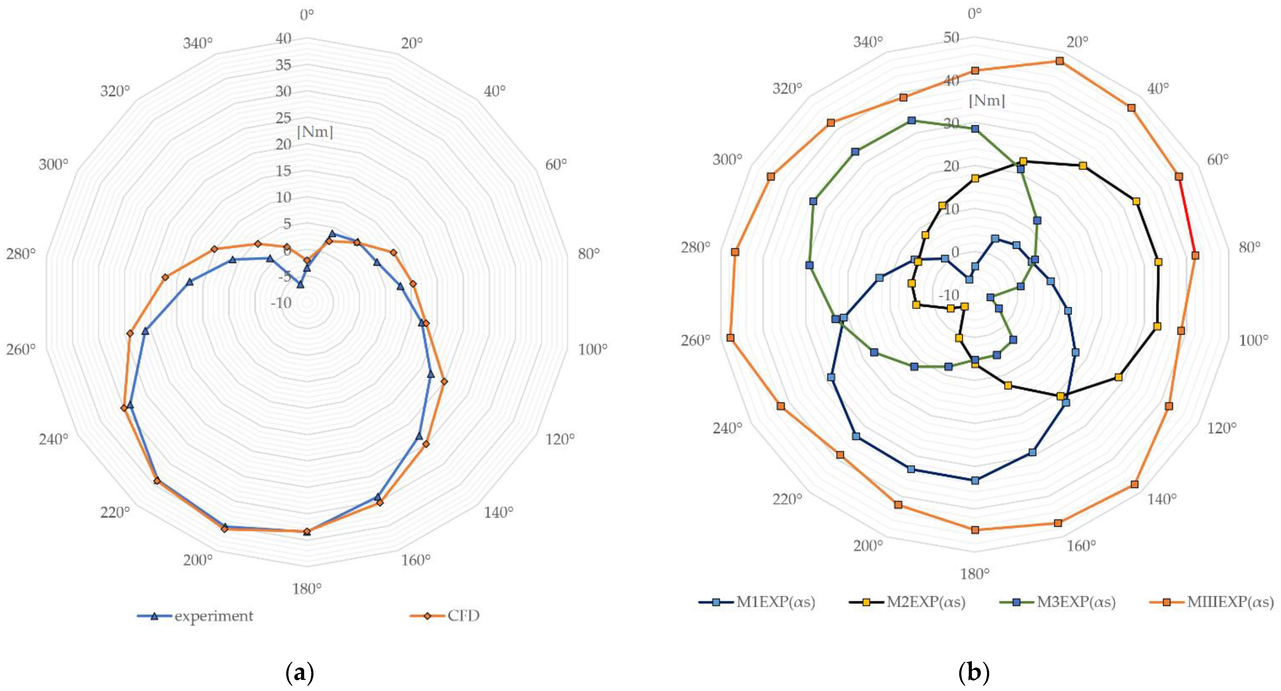
Calculations of Propelling Torque for a Single Blade

The values of the aerodynamic forces Px and Py, as well as the aerodynamic torque Mxy obtained from the measurements and CFD analysis for the single coherent blade in the x, y, z, coordinate system, were used to calculate the values of the forces Rη, Rξ and the torque Mηξ in the η, ξ system, according to Figure 7b. The radius of the rotor R was equal to 1.5 m. The forces Rη, Rξ and the torque Mηξ in the coordinate system η, ξ were calculated for γ = α/2, and fixed for a peripheral speed V0 = 0 and β = 0, using the following equations:
R η = P x c o s α 2 P y s i n α 2
R ξ = P x s i n α 2 + P y c o s α 2
M η ξ = M xy
The obtained values of forces Rη, Rξ are summarized in Figure 17 and Figure 18.
The wind profile and consequently the turbulence intensity profile were not uniform but were the same for all measurements. The values of wind speed and turbulence intensity obtained from the measurements and then adopted for CFD analysis were averaged. This may have caused differences between the experimental and numerical results.
By knowing the values of forces Rη, Rξ and the torque Mηξ in the η, ξ coordinate system, the driving torque provided by the single blade of the carousel wind rotor can be calculated according to Equation (1). The propelling torque M1(αs) generated by the single blade was calculated as a function of the blade position α(αs) relative to the rotor axis, as shown in Figure 19a. Assuming no interference of individual blades, the propelling torque for the rotor with three blades was estimated. Figure 19b shows the total propelling torque for the three rotor blades MIII(αs) relative to the coordinate system η, ξ and for V0 = 0.
The results were obtained using experimental data. The total torque is the sum of the torques of each of the rotor blades according to Equation (2). The obtained values of the propelling torque of the rotor could be used to estimate the maximum peripheral speed of the rotor, which no longer increased as the wind speed increased.

4. Conclusions

A single coherent cross-section of a blade was proposed for a carousel wind rotor. The shape of the blade profile was determined based on a review of NACA airfoils and research on H-rotors. The single-coherent cross-section of the blade was obtained by combining the outlines of two NACA4418 profiles arranged in point symmetry in order to partially take advantage of the aerodynamic properties of the NACA profile while obtaining a blade with two leading points. The use of a blade profile with two leading points is essential according to the working principle of the carousel wind rotor, and is a novelty presented in this study. This is due to the coupling of the blade with the rotor axis by means of a planetary gear with a ratio of 1:2. Consequently, the blade rotates at half the speed of the rotor itself and returns to its starting position every second revolution. The single coherent blade profile provides greater stiffness. Moreover, the additional pair of forces generated by the aerodynamic effect on the blade profile provides additional torque to increase the propelling torque.
A physical model of the blade with the proposed single coherent cross-section was built. Experimental tests were then conducted in a wind tunnel to determine the aerodynamic forces and aerodynamic moment as a function of the wind attack angle.
Numerical CFD analysis was carried out for the same cases and conditions as in the experimental study. The results obtained from the experimental tests were compared with the results of the numerical analysis. Then, based on the obtained results, the driving torque of the carousel wind rotor was calculated.
The results of the experimental and numerical studies, which were mostly consistent with each other, indicate an acceptable methodology for conducting research on the rotor blade profile. Therefore, they indicate the possibility of examining further modifications to the blade profile shape and having high confidence in the numerical results before conducting experimental tests in the wind tunnel.
Further studies on blades and the carousel rotor itself will concern the optimization of the blade cross-section in order to increase its aerodynamic effect, the analysis of the impact of changing the planetary gear ratio on increasing the turbine drive torque, and the development of a rotor design with a planetary gear and an additional flywheel in order to ensure the constant rotation of the rotor and prevent sudden changes in the rotor rotation.

Author Contributions

Conceptualization, M.A. and F.L.; methodology, M.A. and F.L.; software, F.L.; validation, M.A. and F.L.; formal analysis, M.A.; investigation, M.A.; data curation, M.A. and F.L.; writing—original draft preparation, M.A. and F.L.; writing—review and editing, M.A. and F.L.; visualization, M.A. and F.L.; supervision, M.A.; All authors have read and agreed to the published version of the manuscript.

Funding

This research received no external funding.

Data Availability Statement

Not applicable.

Conflicts of Interest

The authors declare no conflict of interest.

References

  1. Hau, E. Wind Turbines: Fundamentals, Technologies, Application, Economics; Springer: Berlin/Heidelberg, Germany, 2013. [Google Scholar] [CrossRef]
  2. Ahmed, S. Wind Energy: Theory and Practice; PHI Learning Pvt. Ltd.: New Delhi, India, 2011; ISBN 9788120351639. [Google Scholar]
  3. Burton, T.; Jenkins, N.; Sharpe, D.; Bossanyi, E. Wind Energy Handbook; John Wiley & Sons, Ltd.: Hoboken, NJ, USA, 2001. [Google Scholar] [CrossRef]
  4. Eriksson, S.; Bernhoff, H.; Leijon, M. Evaluation of different turbine concepts for wind power. Renew. Sustain. Energy Rev. 2008, 12, 1419–1434. [Google Scholar] [CrossRef]
  5. Pope, K.; Dincer, I.; Naterer, G.F. Energy and exergy efficiency comparison of horizontal and vertical axis wind turbines. Renew. Energy 2010, 35, 2102–2113. [Google Scholar] [CrossRef]
  6. Darrieus, G. Turbine Having Its Rotating Shaft Transverse to the Flow of the Current. U.S. Patent 1835018, 8 December 1931. [Google Scholar]
  7. Mohan Kumar, P.; Sivalingam, K.; Lim, T.-C.; Ramakrishna, S.; Wei, H. Review on the Evolution of Darrieus Vertical Axis Wind Turbine: Large Wind Turbines. Clean Technol. 2019, 1, 205–223. [Google Scholar] [CrossRef] [Green Version]
  8. Gorelov, D.N. Energy characteristics of Darrieus rotor (review). Thermophys. Aeromech. 2010, 17, 301–308. [Google Scholar] [CrossRef]
  9. Islam, M.; Ting, D.S.K.; Fartaj, A. Aerodynamic models for Darrieus-type straight-bladed vertical axis wind turbines. Renew. Sustain. Energy Rev. 2008, 12, 1087–1109. [Google Scholar] [CrossRef]
  10. Gharib-Yosry, A.; Blanco-Marigorta, E.; Fernández-Jiménez, A.; Espina-Valdés, R.; Álvarez-Álvarez, E. Wind–Water Experimental Analysis of Small SC-Darrieus Turbine: An Approach for Energy Production in Urban Systems. Sustainability 2021, 13, 5256. [Google Scholar] [CrossRef]
  11. Wakui, T.; Tanzawa, Y.; Hashizume, T.; Nagao, T. Hybrid configuration of Darrieus and Savonius rotors for stand-alone wind turbine-generator systems. Electr. Eng. Jpn. 2005, 150, 13–22. [Google Scholar] [CrossRef]
  12. Mohan Kumar, P.; Surya, M.R.; Sivalingam, K.; Lim, T.-C.; Ramakrishna, S.; Wei, H. Computational Optimization of Adaptive Hybrid Darrieus Turbine: Part 1. Fluids 2019, 4, 90. [Google Scholar] [CrossRef] [Green Version]
  13. Savonius, S.J. The S-rotor and its applications. Mech. Eng. 1931, 53, 333–338. [Google Scholar]
  14. Kamoji, M.A.; Kedare, S.B.; Prabhu, S.V. Experimental investigations on single stage modified Savonius rotor. Appl. Energy 2009, 86, 1064–1073. [Google Scholar] [CrossRef]
  15. Moutsoglou, A.; Yan, W. Performance Tests of a Benesh Wind Turbine Rotor and a Savonius Rotor. Wind Eng. 1995, 19, 349–362. Available online: https://www.jstor.org/stable/43749592 (accessed on 3 May 2023).
  16. Van Bussel, G.; Mertens, S.; Polinder, H.; Sidler, H.F.A. The Development of Turby, a Small VAWT for the Built Environment. In Proceedings of the Global Windpower 2004 Conference, Chicago, IL, USA, 28–31 March 2004. [Google Scholar]
  17. Ghiasi, P.; Najafi, G.; Ghobadian, B.; Jafari, A.; Mazlan, M. Analytical Study of the Impact of Solidity, Chord Length, Number of Blades, Aspect Ratio and Airfoil Type on H-Rotor Darrieus Wind Turbine Performance at Low Reynolds Number. Sustainability 2022, 14, 2623. [Google Scholar] [CrossRef]
  18. Nader, N.A.; Jendoubi, A. Study of a Vertical Axis Wind Turbine for Low Speed Regions in Saudi Arabia. In Proceedings of the 5th International Conference of Fluid Flow, Heat and Mass Transfer (FFHMT’18), Niagara Falls, ON, Canada, 7–9 June 2018. [Google Scholar] [CrossRef]
  19. Ryś, J. Arrangement for Self-Positioning a Wing Motor in Wind’s Eye Position. Patent PAT.170515, 1993. Available online: https://api-ewyszukiwarka.pue.uprp.gov.pl/api/collection/32b800daa77c200e1dab609b1930bd92 (accessed on 9 April 2023). (In Polish).
  20. Ryś, J.; Augustyn, M. Homing a Wind Turbine Arrangement with a Horizontal Axis to the Rotation Wind Direction. Patent PAT.219834, 2015. Available online: https://api-ewyszukiwarka.pue.uprp.gov.pl/api/collection/05ac4a55973e657e16f2e877a94a9f07 (accessed on 9 April 2023). (In Polish).
  21. Rogowski, K.; Hansen, M.O.L.; Bangga, G. Performance Analysis of a H-Darrieus Wind Turbine for a Series of 4-Digit NACA Airfoils. Energies 2020, 13, 3196. [Google Scholar] [CrossRef]
  22. Ostowari, C.; Naik, D. Post-Stall Wind Tunnel Data for NACA 44XX Series Airfoil Sections; U.S. Department of Energy Office of Scientific and Technical Information: Oak Ridge, TN, USA, 1985. [CrossRef] [Green Version]
  23. Wind Engineering Laboratory. Available online: http://www.windlab.pl/en/ (accessed on 20 February 2023).
  24. Ryś, J.; Augustyn, M. Innovative construction of 3-component aerodynamic balance. Adv. Mater. Mach. Des.-Key Eng. Mater. 2013, 542, 171–177. [Google Scholar] [CrossRef]
  25. Augustyn, M.; Barski, M.; Chwał, M.; Stawiarski, A. Numerical and Experimental Determination of the Wind Speed Value Causing Catastrophe of the Scissor Lift. Appl. Sci. 2023, 13, 3528. [Google Scholar] [CrossRef]
  26. Flaga, A.; Kłaput, R.; Augustyn, M. Wind tunnel tests of two free-standing lighting protection masts in different arrangements with surroundings roof objects and roof conditions. Eng. Struct. 2016, 124, 539–548. [Google Scholar] [CrossRef]
  27. Lisowski, F.; Lisowski, E. Determination of Aerodynamic Drag Coefficients of Longitudinal Finned Tubes of LNG Ambient Air Vaporizers Using CFD and Experimental Methods. Appl. Sci. 2022, 12, 10865. [Google Scholar] [CrossRef]
  28. Augustyn, M. Propelling torque of the self-adjusting vertical-axis rotor. IOP Conf. Ser. Mater. Sci. Eng. 2020, 744, 012009. [Google Scholar] [CrossRef]
  29. Augustyn, M. A vertical-axis rotor as the adjusting system of a horizontal axis wind turbine. Tech. Trans. 2020, 117, 1–14. [Google Scholar] [CrossRef]
  30. Wen, J.; Zhou, L.; Zhang, H. Mode interpretation of blade number effects on wake dynamics of small-scale horizontal axis wind turbine. Energy 2023, 263, 125692. [Google Scholar] [CrossRef]
  31. Bhavsar, H.; Roy, S.; Niyas, H. Aerodynamic performance enhancement of the DU99W405 airfoil for horizontal axis wind turbines using slotted airfoil configuration. Energy 2023, 263, 125666. [Google Scholar] [CrossRef]
  32. Vedovelli, M.; Eltayesh, A.; Natili, F.; Castellani, F. Experimental and Numerical Investigation of the Effect of Blades Number on the Dynamic Response of a Small Horizontal-Axis Wind Turbine. Energies 2022, 15, 9134. [Google Scholar] [CrossRef]
  33. Intro to Governing Equations of Fluid Dynamics, 2020; ANSYS Inc.: Canonsburg, PA, USA, 2020; Available online: http://www.ansys.com (accessed on 6 May 2023).
  34. Menter, F.R. Zonal Two Equation k-ω Turbulence Models for Aerodynamic Flows. In Proceedings of the 23rd Fluid Dynamics, Plasmadynamics and Lasers Conference, Orlando, FL, USA, 6–9 July 1993. [Google Scholar] [CrossRef]
  35. Menter, F.R. Two-Equation Eddy-Viscosity Turbulence Models for Engineering Applications. AIAA J. 1994, 32, 1598–1605. [Google Scholar] [CrossRef] [Green Version]
  36. Carraro, M.; De Vanna, F.; Zweiri, F.; Benini, E.; Heidari, A.; Hadavinia, H. CFD Modeling of Wind Turbine Blades with Eroded Leading Edge. Fluids 2022, 7, 302. [Google Scholar] [CrossRef]
  37. Meana-Fernández, A.; Fernández Oro, J.M.; Argüelles Díaz, K.M.; Galdo-Vega, M.; Velarde-Suárez, S. Application of Richardson extrapolation method to the CFD simulation of vertical-axis wind turbines and analysis of the flow field. Eng. Appl. Comput. Fluid Mech. 2019, 13, 359–376. [Google Scholar] [CrossRef] [Green Version]
  38. Gantasala, S.; Tabatabaei, N.; Cervantes, M.; Aidanpää, J.-O. Numerical Investigation of the Aeroelastic Behavior of a Wind Turbine with Iced Blades. Energies 2019, 12, 2422. [Google Scholar] [CrossRef] [Green Version]
  39. Wilcox, D.C. Formulation of the k-omega Turbulence Model Revisited. AIAA J. 2008, 46, 2823–2838. [Google Scholar] [CrossRef] [Green Version]
  40. Chien, K.-Y. Predictions of Channel and Boundary-Layer Flows with a Low-Reynolds-Number Turbulence Model. AIAA J. 1982, 20, 33–38. [Google Scholar] [CrossRef]
  41. Ansys Fluent Theory Guide. Available online: https://www.afs.enea.it/project/neptunius/docs/fluent/html/th/node67.htm (accessed on 9 April 2023).
  42. Lisowski, F.; Lisowski, E. Influence of Longitudinal Fin Tubes Arrangement in LNG Ambient Air Vaporizers on the Wind Load. Energies 2022, 15, 405. [Google Scholar] [CrossRef]
  43. Zhang, H.; Li, Z.; Xin, D.; Zhan, J. Improvement of Aerodynamic Performance of Savonius Wind Rotor Using Straight-Arc Curtain. Appl. Sci. 2020, 10, 7216. [Google Scholar] [CrossRef]
Figure 1. Basic types of vertical axis wind rotors: (a) Darrieus, (b) Savonius, (c) H-type.
Energies 16 05532 g001
Figure 2. Carousel wind rotor: (a) structural design, (b) planetary gear.
Energies 16 05532 g002
Figure 3. Scheme of the forces acting on the single rotor blade for the selected positions relative to the rotor axis (VAWT), where V is the wind speed relative to the turbine blade [m/s]; V0 is the peripheral speed of the rotor [m/s]; W is the wind speed [m/s]; Rξ, Rη and Mηξ are the forces and the torque acting on the blade in the moving coordinate system, α is the angle of the rotor rotation, and the position of the blade relative to the rotor, α = 0–2π [rad] (α = αs in numerical calculations [°]); γ is the wind attack angle on the turbine blade, γ = α/2 [°]; β is the angle of the wind stream operation relative to the rotor [°]; and R is the radius of the rotor [m].
Energies 16 05532 g003
Figure 4. The basis for determining the geometry of a single coherent blade cross-section: (a) NACA 4418 airfoil; (b) outline of single coherent blade; (c) dimensions of single coherent cross-section.
Energies 16 05532 g004
Figure 5. Aerodynamic effect increasing the blade torque [19].
Energies 16 05532 g005
Figure 6. Wind tunnel tests: (a) measurement section with the single coherent blade, (b) the averaged wind profile (Wref = 12.5 m/s).
Energies 16 05532 g006
Figure 7. The orientation of the model in the coordinate system x, y, z and the aerodynamic test conditions: (a) The scheme of the measuring system (1—the tested blade, 2—the five-component aerodynamic balance, 3—amplifier module with data acquisition systems, 4—the turntable with stepper motor, 5—the motor step control system, 6—the pressure sensors located in the x, z plane, 7—the pressure scanner, 8—DaqBook card, 9—PC); (b) The assumed wind direction W; the angle of diverting the wind β; the aerodynamic torque Mx; and aerodynamic forces Px and Py.
Energies 16 05532 g007
Figure 8. (a) Discrete model with boundary condition for the single coherent blade (γ = 40°), (b) detailed view of the inflation layer mesh.
Energies 16 05532 g008
Figure 9. Mesh validation results for the wind attack angle γ = 20°.
Energies 16 05532 g009
Figure 10. Aerodynamic drag Px as function of the wind attack angle γ.
Energies 16 05532 g010
Figure 11. Lift force Py as function of the wind attack angle γ.
Energies 16 05532 g011
Figure 12. Aerodynamic torque Mxy as function of the wind attack angle γ.
Energies 16 05532 g012
Figure 13. (a) Velocity distribution; (b) pressure distribution for wind angle γ = 0°.
Energies 16 05532 g013
Figure 14. (a) Velocity distribution; (b) pressure distribution for wind angle γ = 20°.
Energies 16 05532 g014
Figure 15. (a) Velocity distribution; (b) pressure distribution for wind angle γ = 40°.
Energies 16 05532 g015
Figure 16. (a) Velocity distribution (b) pressure distribution for wind angle γ = 140°.
Energies 16 05532 g016
Figure 17. Aerodynamic force Rη as a function of the wind attack angle γ in the η, ξ coordinate system.
Energies 16 05532 g017
Figure 18. Aerodynamic force Rξ as a function of the wind attack angle γ in the η, ξ coordinate system.
Energies 16 05532 g018
Figure 19. The propelling torque as a function of the blade position α(αs) relative to the rotor axis: (a) M1(αs) generated by one blade, (b) MIII(αs) generated by three blades.
Energies 16 05532 g019
Table 1. Overall dimensions of the tested blade model.
Dimension NameValue
width of the rotor blade [m]aS = 0.250
length of the blade [m]bS = 0.044
height of the rotor blade [m]h = 0.625
Table 2. Characteristics of measurement parameters.
ParameterValue
Geometric scale kD1:1
Mean values of wind speed Wref [m/s]12.5
Mean value of dynamic pressure qref [N/m2]96.4
Mean turbulence intensity IW [%]8
Number of considered wind directions18 (0°–180°)
Disclaimer/Publisher’s Note: The statements, opinions and data contained in all publications are solely those of the individual author(s) and contributor(s) and not of MDPI and/or the editor(s). MDPI and/or the editor(s) disclaim responsibility for any injury to people or property resulting from any ideas, methods, instructions or products referred to in the content.

