Article

Experimental Investigation of a Self-Sustained Liquid Fuel Burner Using Inert Porous Media

School of Mechanical Engineering, Xi’an University of Science and Technology, Xi’an 710054, China
*
Author to whom correspondence should be addressed.
Energies 2023, 16(14), 5564; https://doi.org/10.3390/en16145564
Submission received: 11 June 2023 / Revised: 3 July 2023 / Accepted: 13 July 2023 / Published: 23 July 2023
(This article belongs to the Section I1: Fuel)

Abstract

:
A self-sustained porous burner without a sprayed atomizer was built for diesel oil. It consisted of metal fiber felt as an evaporator upstream and ceramic foam as an emitter downstream. The liquid fuel underwent film boiling in the porous evaporator and was rapidly evaporated by the heat recirculated from the porous emitter to the porous evaporator through intense irradiative heat flux. The effect of the porous structure and its installation location on the performance of the porous burner was investigated. The results indicated that the evaporation and combustion of liquid fuel could be prompted by the radiation of porous media. The position of the flame moved downstream, and the flame temperature decreased when the distance between the metal fiber felt and the ceramic foam was increased. The lowest NOx concentration was obtained when the distance between the foam and the metal fiber felt was 90 mm. When the diameter of the central hole of the ceramic foam was increased, the position of the flame moved towards the burner outlet, and the flame temperature and NOx emission declined. The flame temperature of the divergent configuration as emitter was higher than that of the convergent configuration, and the flame temperature of the C–D configuration was higher than that of the D–C configuration. Different ceramic foam structures had a significant effect on the temperature and emission in the combustion chamber, which showed that the evaporation and radiation performance of inert porous media burners with different structures is quite different.

1. Introduction

Combustion in porous media refers to the replacement of free space with porous materials in the reaction region. The heat generated by combustion is fed back to the fresh mixture of reactant upstream due to the radiation properties and heat storage of porous media [1,2]. Compared with a free flame, porous media combustion has many advantages, such as extended flame stability, lower emissions, wide turn-down ratio, and compact structure [3,4]. Many excellent reviews [5,6] have been published on this interesting topic. It also has attracted much attention and has been applied in civil heaters, dryers, gas turbine combustors, car heating systems, and other areas.
The burner performance can be improved by the radiation and conductivity of the porous media. The heat and mass transfer in the burner is influenced due to the porosity of the media, which in turn influences pollutant emission and flame stability [7]. The research of Pan et al. [8] showed the combustion efficiency of a micro-combustor could be improved with the appropriate parameters and structure of porous media. Vahidhosseini et al. [9] found that high-pore-density SiC porous foam could enhance the internal radiation efficiency of a burner. Djordjevic et al. [10] reported that the flame stability limit of a porous burner was extended compared to a free flame. Xie et al. [11] investigated the flame temperature and pressure loss of CH4 in a burner filled with ceramic foam and alumina pellets of different sizes. The study results showed that the structure and material of the porous media had an important impact on the burner performance. Gao et al. [12] investigated the effect of different downstream materials on pollutant emission and pressure drop in a porous burner. Peng et al. [13] demonstrated that low porosity of the porous media was advantageous in improving heat transfer and flame stability, but not conducive to promoting flame propagation.
The high thermal radiation ability of porous media can also promote the evaporation of liquid droplets. Kaplan and Hall [14] first obtained stable combustion of liquid fuel in SiC- and magnesia-stabilized zirconia porous media using heptane provided by fuel injectors. They revealed that the distance between ceramic porous media and the atomizer had a significant impact on stable combustion. Tseng and Howell [15] numerically studied the evaporation of heptane droplets in the inlet airflow, and their study showed that a 3 cm upstream area was sufficient to completely evaporate droplets with an initial diameter of up to 25 μm at the burner inlet. Vijaykant et al. [16] designed a double-layer porous burner for liquid fuel with preheating and combustion sections using a carbon-foam porous medium coated with SiC. The position of the fuel nozzle has a great influence on combustion emissions. When the nozzle was far enough away from the porous medium, the fuel droplets could completely evaporate. Periasamy et al. [17] established a computational model to predict the evaporation characteristics of liquid fuel in porous media. They discovered that the temperature of the porous medium and its resulting thermal effects were critical factors in achieving complete evaporation of the spray. Weclas et al. [18] revealed that the arrangement of porous media in the spray space could effectively shorten the penetration distance of the fuel spray and promote the fragmentation of fuel droplets, distributing the fuel more evenly and making it easier to achieve a similar effect of homogeneous combustion. Liu et al. [19] established a 2D numerical model to test the combustion mechanism of n-heptane spray in a porous burner. The results indicated that the downstream flame speed increased as the fuel injection rate and preheating temperature decreased or the velocity of the inlet air increased.
A liquid fuel system self-sustained by the thermal circulation of combustion has also been investigated in the past. Agrawal et al. [20] designed an annular counter-current thermal circulation combustor in which kerosene was dropped onto a porous surface under the influence of gravity and evaporated by thermal conduction through the walls. Makmool et al. [21] developed a high-pressure self-aspirating burner using liquid ethanol, in which self-evaporation of liquid ethanol was achieved by embedding the evaporator tube into the burner wall. Sharma et al. [22] studied the influence of different combinations of SiC and Al2O3 structures on the operation performance of a kerosene pressure stove. The optimal combination of SiC and Al2O3 was found to meet the requirement of completely retaining the flame in the porous media.
The evaporation and combustion of liquid fuel can be prompted by the radiation of porous media. The fuel is usually supplied using a dropwise method in the porous medium. The liquid fuel evaporates into a gas before coming into contact with the main combustion area of the porous medium. Similarly to premixed combustion, after mixing with the oxidants, the fuel then enters the main combustion zone for combustion. Takami et al. [23] developed a liquid fuel porous burner without an atomizer, which supplied kerosene dropwise into the metal mesh, and used porous ceramics as fuel distributors and evaporators. The experimental results showed that the lean-burn limit equivalent ratio of kerosene could be extended to 0.1, and the turndown ratio could reach 7.2. Fuse et al. [24] reported that a self-sustaining liquid-fuel evaporative combustion system was feasible as the radiation heat recovery rate was higher than 2% of the heat generated by combustion. Jugjai et al. [25,26,27] developed a liquid-fuel porous burner without a sprayed injector. The liquid fuel evaporated as it passed through the upstream porous medium, then mixed with air at the vortex chamber, and finally burned downstream. The combustion efficiency was effectively improved, and the NOx emission was reduced. It has been shown that changing the length and installation position of the packed bed is an effective way to enhance evaporation and combustion. Wongwatcharaphon et al. [28] reported that the kerosene in the porous evaporator could be completely evaporated and self-sustained by the thermal radiation of the porous combustion chamber. Compared to conventional spray burners, the spray-free porous burner had a higher modulation ratio and a wider equivalence ratio.
Many studies have been conducted on porous burners for liquid fuel in the past decades, showing that porous media are very important to the performance of the whole burner. However, there are few works on the influence of the porous structure on the burner performance. In order to study the effect principle of a ceramic foam structure on the evaporation and radiation characteristics of liquid fuel within inert porous media during combustion, a self-sustaining evaporative atomization porous media burner with diesel as fuel was established and ceramic foam was used as the internal filler of the burner. The effect of the distance between the metal fiber felt and the ceramic foam and the combined structure of the ceramic foam on the temperature and emission in the burner was also studied.

2. Experimental Setup

The schematic diagram of the experimental device is shown in Figure 1. It consisted of the supply system for fuel/air, a porous burner, and measuring and data processing equipment. The air was supplied by a high-pressure blower which was adjusted by a frequency converter and then measured by a gas mass flowmeter (Model: MF5619-N-800-AB-D-A). The diesel oil was supplied by a pulse pump (Model: P0622) and measured by an electronic scale and stopwatch. The lower heating value of diesel oil was 42.9 MJ/kg. The porous burner consisted of two main cylindrical porous media, the upstream metal fiber felt as a porous evaporator and the downstream ceramic foams as a porous emitter. The liquid fuel underwent film boiling in the porous evaporator and was rapidly evaporated by the heat recirculating from the porous emitter to the porous evaporator through intense irradiative heat flux. In other words, the continuous evaporation and combustion in the porous burner were achieved through the coupling effect of the porous evaporator and porous emitter by a strong irradiative heat flux. The porous evaporator is made of FeCrAl metal fiber felt with a thickness of 3 mm, a fiber diameter of 100 μm and a porosity of 0.8. And the porous emitter is made of a packed bed of 10 PPI SiC foams with a diameter of 80 mm, which is provided by FILTEC PRECISION CERAMICS CO., LTD. (Foshan, Guangdong Province, China) as shown in Figure 2. The mixture of fuel and air was first ignited at the surface of the evaporator by a glow plug of silicon nitride at a high temperature of 800–900 °C, and then switched to the setting rate of fuel/air after a preheating phase.
Firstly, the blower was started to take away the impurity gas in the burner to improve the accuracy of the experiment. After 20 s, the oil pump was started and the oil supply was adjusted to 600 g/h through the controller, and then the glow plug was opened for ignition. When the measured temperature near the metal fiber felt reached 300 °C, the ignition was considered successful, and then the glow plug could be switched off. If the temperature fluctuations did not exceed 10 °C within 10 min, the temperature in the combustion chamber was recorded. The concentration of NOx in the flue gas was obtained by Testo350 M/XL. Different excess air coefficients were controlled by adjusting the air supply volume of the high-pressure blower, so as to carry out experiments under different working conditions. After the completion of each experiment, it was necessary to wait until the temperature in the whole combustion chamber was cooled to room temperature. In order to reduce the error, the flue gas probe must be taken out of the exhaust channel after each measurement, and the residual gas must be removed with air. The liquid fuel used in this experiment is 0# diesel, and its elements component is shown in Table 1.
The mass fraction of oxygen in the air is 0.233. The theoretical mass of air required for the complete combustion of carbon, hydrogen, and sulfur per gram of diesel oil is shown in Equations (1)–(3), respectively.
M C = 85.55 % 12 × 32 0.233
M H = 13.49 % 4 × 32 0.233
M S = 0.25 % 32 × 32 0.233
The actual mass of air corresponding to different excess air coefficients is shown in Equation (4).
M = λ × ( M C + M H + M S )
where λ is the excess air coefficient. At normal temperature and pressure, the density of air is 1.2 kg/m3, and the air volume per gram of diesel oil with different excess air coefficients is shown in Table 2.
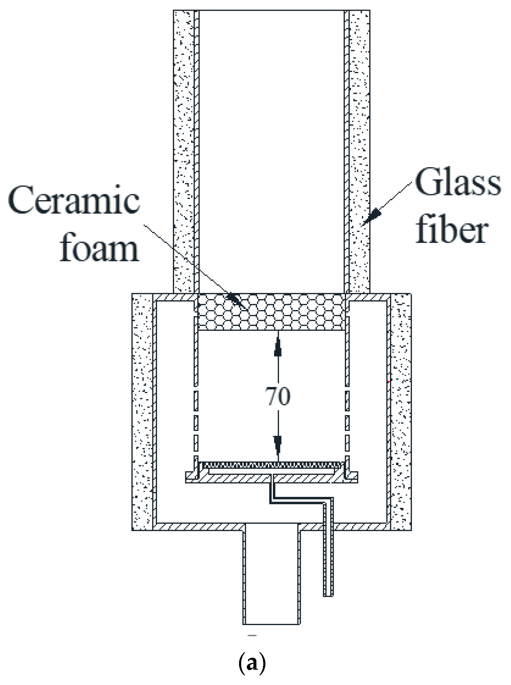
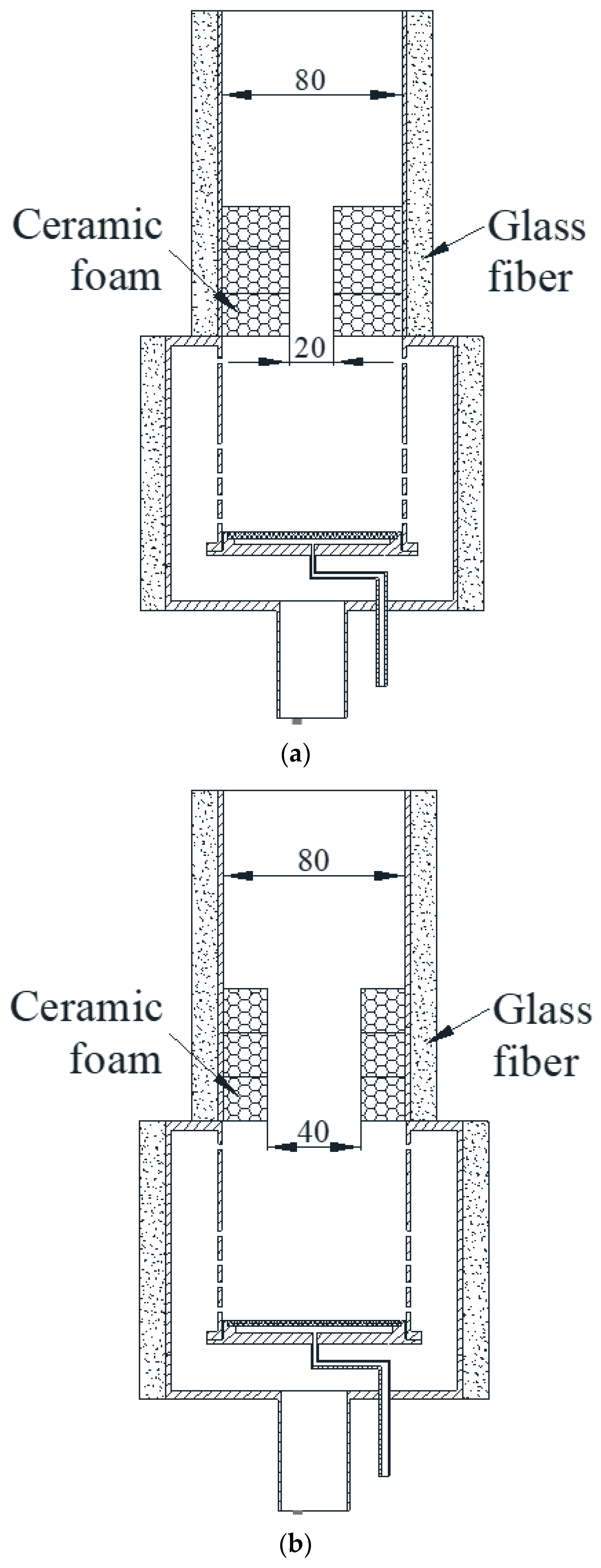
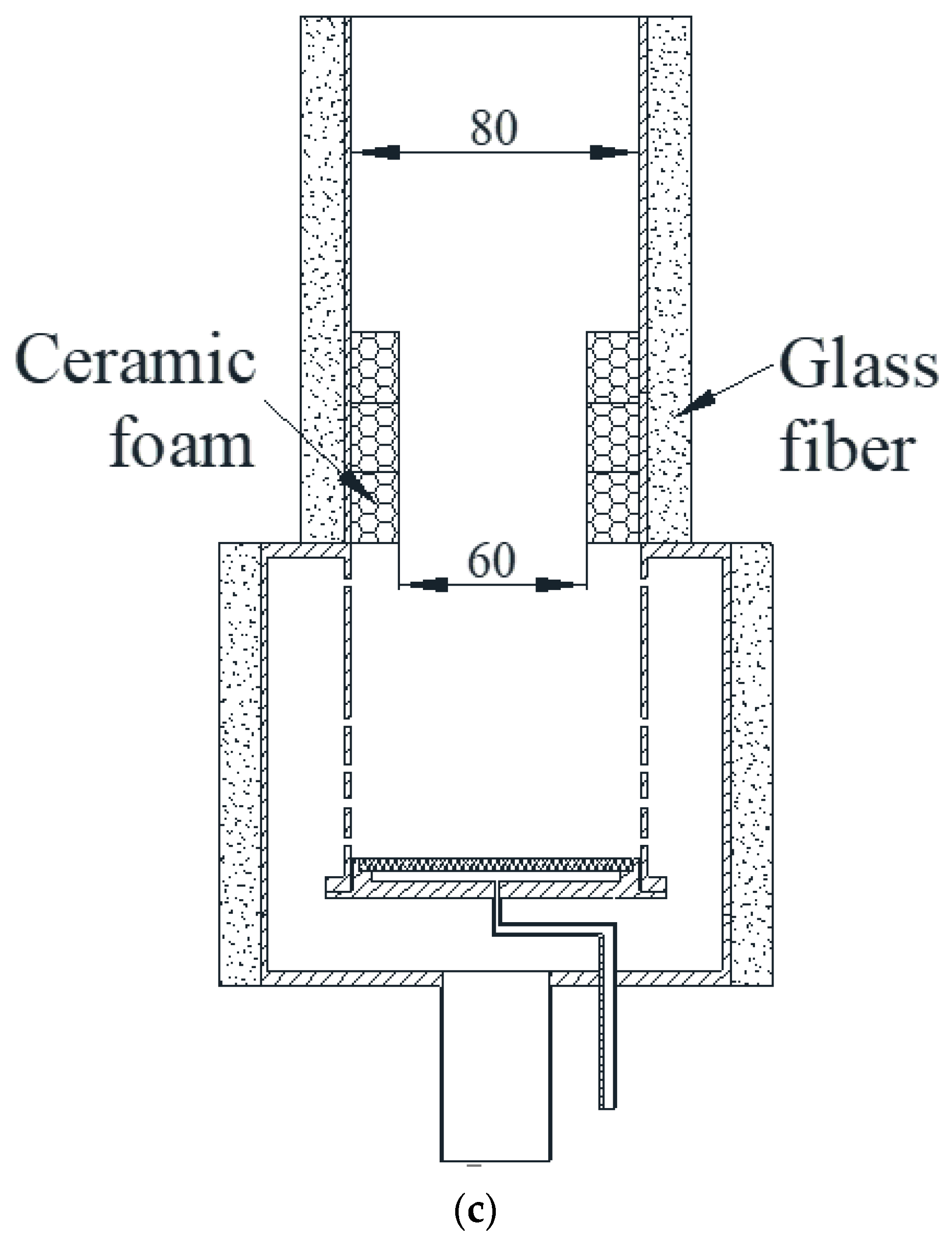
The effect of the distance between the porous evaporator and porous emitter (i.e., 70, 90, and 110 mm) on the burner performance was discussed and the corresponding burner structure is shown in Figure 3. The effect of the central hole diameter (i.e., 20, 40, and 60 mm) of ceramic foams (thickness of 60 mm) on the burner performance was conducted and the corresponding burner structure is shown in Figure 4. The effect of the porous structure which was made of ceramic foams with different central hole diameters on the burner performance was also reported and the corresponding burner structure is shown in Figure 5, namely, Convergent (C configuration), Divergent (D configuration), Convergent–Divergent (C–D configuration) and Divergent–Convergent (D–C configuration).
The temperature distribution was measured by nine K-type armored thermocouples. These thermocouples were inserted into the combustion chamber through small holes in the burner wall and had an accuracy of 0.25% at the range of 0~1400 °C. The NOx emission was measured and recorded by a Testo 350M/XL analyzer, which had an accuracy of ±5 ppm. The uncertainties of the temperature, pollutant emissions, fuel supplied rate and gas flowmeter were calculated as 1.2% (±6.459 °C), 5% (±5 ppm), 2% (±12 g/h), and 2.5% (±4.758 L/min), respectively, using the root-sum-squares method [29].

3. Results and Discussion

3.1. Effect of the Distance between Foam and Metal Fiber Felt

The evaporation of liquid fuel is significantly influenced by heat recirculation effects of porous media in the burner, especially by the distance between the evaporator and emitter. The influence of the distance between the metal fiber felt and foam on the flame temperature distribution is shown in Figure 6. Generally, the overall shape of the flame temperature distribution is similar for various excess air coefficients, which decreases with the increase in excess air coefficient. The flame temperature increases rapidly along the axial direction, and then drops slowly after reaching the peak value. The flame temperature decreases with the increasing distance between the metal fiber felt and foam. On the one hand, the evaporation of the liquid fuel is attenuated due to lower heat recirculation from the foam when the distance between the foam and the metal fiber felt increases. On the other hand, more heat is carried outside the burner by the flue gas, and the heat lost by the thermal radiation from the foam to the environment increases with the increasing distance between the foam and metal fiber felt. Furthermore, the position of the flame moves downstream with the increasing distance between the foam and metal fiber felt. The position of the flame in the burner is 34 mm from the inlet when the distance between the foam and metal fiber felt is 70 mm. The position of the flame is located at 44 mm, 54 mm from the burner inlet when the distance between the foam and metal fiber felt is 90 mm and 110 mm, respectively. This is because the thermal feedback from the foam to the upstream region is weakened when the foam moved downstream. When δ = 70 mm and 90 mm, the temperature of the ceramic foam on the downstream side has a small recovery stage. But when δ = 110 mm, the temperature of the ceramic foam on the downstream side continues decreasing, and the rate of decrease is faster than the other two. It shows that the thermal feedback ability from the ceramic foam to the upstream region of the burner is weakened with the increasing distance between the ceramic foam and the metal fiber felt.
The influence of the distance between the metal fiber felt and foam on the NOx emissions is shown in Figure 7. The NOx emission decreases with the increase in excess air coefficient due to the corresponding flame temperature as shown in Figure 6. The NOx emission firstly decreases and then increases with the increasing distance between the metal fiber felt and foam. The NOx concentration in flue gas is the lowest when the distance between the foam and metal fiber felt is 90 mm in the present work. The NOx emission is decided by the flame temperature and residence time of the reactants passing through the high-temperature zone. With the increasing distance between the metal fiber felt and foam, the flame temperature declines, suppressing NOx generation as shown in Figure 6. However, the residence time of the reactants in the high-temperature zone increases, which promotes the generation of NOx. Under the joint action of the two abovementioned opposite factors, the lowest NOx emission is obtained with a distance of 90 mm between the metal fiber felt and the foam. Therefore, the position of ceramic foam with δ = 90 mm is the best among the three, which has excellent thermal radiation inside the burner and the lowest NOx emission.

3.2. Effect of the Central Hole Diameter

Figure 8 shows the axial temperature distribution with a fuel supply rate of 600 g/h for different diameters of the central hole, d = [20, 40, and 60 mm]. The flame temperature decreases with the increasing diameter of the central hole, and the position of the flame moves downstream. At the same time, with the increase in excess air coefficient, the flame temperature decreases. For the same diameter of the central hole, the axial temperature distribution of different excess air coefficients is similar. As can be seen from Figure 8, when the diameter of the central hole is 20 mm and 40 mm, the axial temperature distribution trend of the burner is basically the same, and the peak temperature for the central hole diameter of 20 mm is slightly higher than that for the central hole diameter of 40 mm. However, when the diameter of the central hole is 60 mm, there is a temperature trough at the position of X = 35 mm and a temperature peak at the position of X = 75 mm. This is because with the increase in the diameter of the central hole, more fuel and air mixtures pass through the central hole of the foam rather than the porous medium due to the lower flow resistance. Therefore, the thermal radiation ability of ceramic foam to the inside of the burner is weakened, and more heat is carried out of the porous burner into the environment by the flue gas. Therefore, it is necessary to avoid excessive central hole diameter to improve the performance of the burner.
Figure 9 shows the NOx emission in the porous burner with a fuel supply rate of 600 g/h for different diameters of the central hole, d = [20, 40 and 60 mm]. Similarly, the NOx emission is decreased with the increasing excess air coefficient due to the corresponding flame temperature as shown in Figure 8. The NOx emission is decreased with the increasing diameter of the central hole. The reason is that the generation of NOx depends on the flame temperature and residence time of the fuel/air mixture passing through the region of high temperature. As the diameter of the central hole increases, the flame temperature declines, suppressing NOx production, as shown in Figure 8. Moreover, more reactant mixture passes through the central hole of the foam rather than flowing through the ceramic foam. Therefore, the residence time of the reactant mixture in the high-temperature zone is shortened, which inhibits the generation of NOx.

3.3. Effect of Porous Media Configuration

Figure 10 shows the axial temperature distribution with a fuel supply rate of 600 g/h for the C configuration and D configuration as the emitter. Similar to the aforementioned, the flame temperature decreases with the increase in excess air coefficient due to the dilution effect. The flame temperature of the D configuration is higher than that of the C configuration, and the smaller the excess air coefficient, the more significant the difference between the peak temperature of the C configuration and D configuration. The position of the flame is located at 34 mm from the inlet for both the C configuration and D configuration as the emitter. For the case of the D configuration, the temperature increases rapidly along the axial direction, and then drops slowly after reaching the peak value. However, there is another peak temperature in the ceramic foam zone for the C configuration. As can be seen from Figure 10, for these two configurations, the ceramic foam with the smallest central hole diameter plays a leading role in the internal radiation ability of the burner. There is a larger flow resistance for the smaller central hole diameter of foams, causing more mixtures of fuel/air to react upstream in the burner. For the C configuration as emitter, the hole diameter of foam gradually decreases along the axial direction, the foam with the smallest hole diameter is located downstream, which has a significant impact on the combustion reaction. This configuration results in a lower peak temperature in the burner than that of the D configuration, but the temperature in the ceramic foam area is higher than that in the D configuration. However, the hole diameter gradually increases along the axial direction for the D configuration, and the foam with the smallest hole diameter is located upstream, which makes the upstream temperature significantly higher than that of the C configuration.
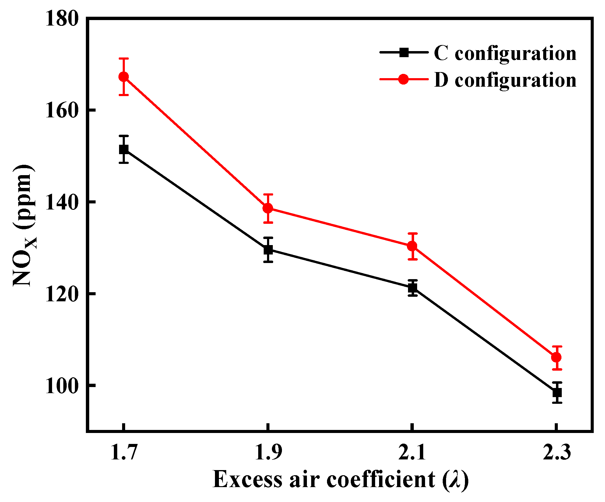
Figure 11 shows the NOx emission in the porous burner with a fuel supply rate of 600 g/h for the C configuration and D configuration as the emitter. Similarly, the NOx emission decreases with the increase in excess air coefficient due to the corresponding flame temperature as shown in Figure 10. The production of NOx depends on the flame temperature and residence time of fuel/air mixture passing through the high-temperature zone. The flame temperature of the D configuration as an emitter is higher than that of the C configuration, whereas there is a shorter residence time for the reactants passing through the high-temperature zone for the D configuration compared with the C configuration. The higher flame temperature promotes NOx production, while the shorter residence time suppresses the production of NOx. The above two factors compete with each other, the NOx emission in the burner of the D configuration is higher than that of the C configuration.
Figure 12 shows the axial temperature distribution with a fuel supply rate of 600 g/h for the C–D configuration and D–C configuration as an emitter. The flame temperature of the C–D configuration as an emitter is higher than that of the D–C configuration. The flame is located 24 mm from the inlet for both the C–D configuration and D–C configuration. For the C–D configuration, the temperature increases rapidly along the axial direction, and then drops after reaching the peak value. As can be seen from Figure 12, the temperature distribution trend under different excess air coefficients in the same configuration is similar. By comparing the axial temperature distribution of these two configurations, an interesting phenomenon can be found. The upstream peak temperature of the C–D configuration is higher than that of the D–C configuration, but the temperature of the D–C configuration is higher than that of the C–D configuration in the ceramic foam area. The reason for this phenomenon is that in the D–C configuration, the ceramic foam with a smaller central hole diameter is located at both sides of the combustion chamber, which can limit the heat in the ceramic foam area, making the temperature in the ceramic foam area of the D–C configuration higher. However, in the C–D configuration, the ceramic foam with a smaller central hole diameter is located side by side in the middle of the burner, and its thickness increases, which leads to higher upstream temperature in the C–D configuration. This shows that the ceramic foam with a smaller central hole diameter can better balance the axial temperature distribution inside the burner.
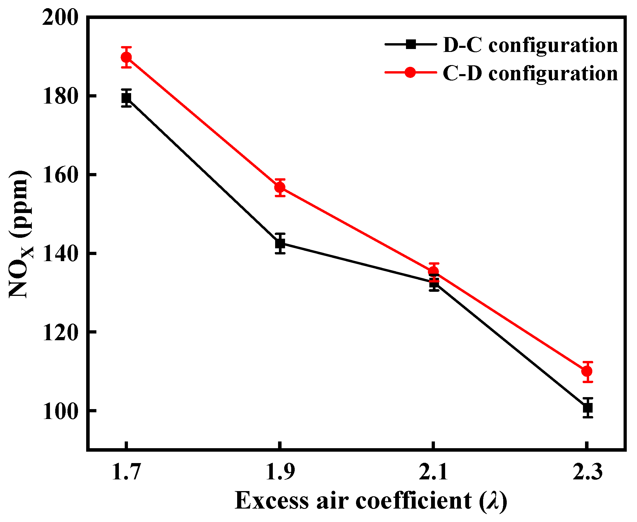
Figure 13 shows the NOx emission in the porous burner with a fuel supply rate of 600 g/h for the C–D configuration and D–C configuration as an emitter. Similarly, the NOx emission decreases with the increase in excess air coefficient due to the corresponding flame temperature as shown in Figure 12. The production of NOx depends on the flame temperature and residence time of the reactants passing through high-temperature zone. The flame temperature of the C–D configuration as an emitter is higher than that of the D–C configuration, whereas there is a shorter residence time for a porous burner with an emitter of the C–D configuration compared with that of the D–C configuration. The higher flame temperature promotes NOx production, while the shorter residence time suppresses the production of NOx. The two opposing factors mentioned compete with each other, the NOx emission in the burner of the C–D configuration is higher than that of the D–C configuration. In addition, the better thermal radiation uniformity of the D–C configuration is also the reason for the lower NOx emission.

4. Conclusions

The combustion performance of diesel oil in porous media without a sprayed atomizer was investigated in the present work. The effects of the distance between the ceramic foams and the metal fiber felt, the diameter of the central hole of ceramic foams, and different combinations of ceramic foams on the performance of liquid fuel combustion were studied. The main results are summarized as follows:
(1)
The position of the flame moves downstream, and the flame temperature simultaneously decreases when the distance between the metal fiber felt and foams increases. The NOx emission firstly reduces and then increases with the increasing distance between the foam and the metal fiber felt. The lowest NOx concentration is obtained when the distance between the foam and the metal fiber felt is 90 mm. The results show that distance has a great influence on the temperature and emission inside the burner, and excessive distance is not conducive to the combustion of liquid fuel and the performance of the burner.
(2)
The overall distribution along the axial direction and NOx emission declines with the increasing diameter of the central hole of porous media. Furthermore, the position of the flame moves towards the burner outlet with the increasing diameter of the central hole. This shows that the increasing diameter of the central hole weakens the thermal storage capacity of ceramic foam and leads to the decreasing internal temperature of the burner, which is not conducive to the evaporation of liquid fuel. On the whole, when the central hole diameter is 40 mm and the excess air coefficient is 2.3, the comprehensive temperature and emission performance can be considered an ideal situation.
(3)
Compared with the D configuration and C–D configuration, the axial temperature distribution of the C configuration and D–C configuration is more uniform and NOx emission is less. At the same time, the axial temperature distribution in the combustion chamber can be balanced by properly arranging the ceramic foam with the different diameters of the central hole, so that the thermal radiation is more uniform.
(4)
The presence of inert porous media in the burner has a notable impact on heat radiation and heat transfer. Experimental findings indicate that ceramic foam can increase the heat storage capacity within the burner to some extent, thereby facilitating the evaporation and self-sustaining combustion of liquid fuel. The objective of the upcoming research will be to simultaneously reduce emissions and enhance heat transfer.

Author Contributions

Conceptualization, H.G.; methodology, H.G. and S.Z.; validation, H.G. and Y.M.; formal analysis, H.G. and S.Z.; investigation, H.G. and Y.W.; resources, H.G.; data curation, H.G.; writing—original draft preparation, H.G.; writing—review and editing, H.G. and Y.W.; visualization, H.G.; supervision, H.G. and C.Z.; project administration, H.G.; funding acquisition, H.G. All authors have read and agreed to the published version of the manuscript.

Funding

This research was funded by the National Natural Science Foundation of China grant number 52176132 and Innovation Capability Support Program of Shaanxi grant number 2021TD-27.

Data Availability Statement

Data sharing not applicable.

Conflicts of Interest

The authors declare no conflict of interest.

References

  1. Howell, J.; Hall, M.; Ellzey, J. Combustion of hydrocarbon fuels within porous inert media. Prog. Energy Combust. Sci. 1996, 22, 121–145. [Google Scholar] [CrossRef]
  2. Oliveira, A.; Kaviany, M. Nonequilibrium in the transport of heat and reactants in combustion in porous media. Prog. Energy Combust. Sci. 2001, 27, 523–545. [Google Scholar] [CrossRef]
  3. Bubnovich, V.; Toledo, M.; Henríquez, L.; Rosas, C.; Romero, J. Flame stabilization between two beds of alumina balls in a porous burner. Appl. Therm. Eng. 2010, 30, 92–95. [Google Scholar] [CrossRef]
  4. Mujeebu, M.A.; Abdullah, M.Z.; Mohamad, A.; Bakar, M.A. Trends in modeling of porous media combustion. Prog. Energy Combust. Sci. 2010, 36, 627–650. [Google Scholar] [CrossRef]
  5. Mujeebu, M.A.; Abdullah, M.Z.; Bakar, M.Z.A.; Mohamad, A.A.; Abdullah, M.K. Applications of porous media combustion technology—A review. Appl. Energy 2009, 86, 1365–1375. [Google Scholar] [CrossRef]
  6. Aboujafari, M.; Valipour, M.S.; Hajialimohammadi, A.; Honnery, D. Porous Medium Applications in Internal Combustion Engines: A Review. Transp. Porous Media 2022, 141, 799–824. [Google Scholar] [CrossRef]
  7. Yang, W.M.; Chou, S.K.; Chua, K.J.; Li, J.; Zhao, X. Research on modular micro combustor-radiator with and without porous media. Chem. Eng. J. 2011, 168, 799–802. [Google Scholar] [CrossRef]
  8. Pan, J.F.; Wu, D.; Liu, Y.X.; Zhang, H.F.; Tang, A.K.; Xue, H. Hydrogen/oxygen premixed combustion characteristics in micro porous media combustor. Appl. Energy 2015, 160, 802–807. [Google Scholar] [CrossRef]
  9. Vahidhosseini, S.M.; Esfahani, J.A.; Kim, K.C. Experimental study on the radiative heat transfer in a multi-hole porous radiant burner with internal combustion regime. Appl. Therm. Eng. 2022, 201, 117732. [Google Scholar] [CrossRef]
  10. Djordjevic, N.; Habisreuther, P.; Zarzalis, N. Flame stabilization and emissions of a natural gas/air ceramic porous burner. Adv. Mat. Res. 2008, 47, 105–108. [Google Scholar] [CrossRef]
  11. Xie, M.Z.; Shi, J.R.; Deng, Y.B.; Liu, H.; Zhou, L.; Xu, Y.N. Experimental and numerical investigation on performance of a porous medium burner with reciprocating flow. Fuel 2009, 88, 206–213. [Google Scholar]
  12. Gao, H.; Qu, Z.; Feng, X.; Tao, W. Methane/air premixed combustion in a two-layer porous burner with different foam materials. Fuel 2014, 115, 154–161. [Google Scholar] [CrossRef]
  13. Peng, Q.; Xie, B.; Yang, W.; Tang, S.; Li, Z.; Zhou, P.; Luo, N. Effects of porosity and multilayers of porous medium on the hydrogen-fueled combustion and micro-thermophotovoltaic. Renew. Energy 2021, 174, 391–402. [Google Scholar] [CrossRef]
  14. Kaplan, M.; Hall, M.J. The combustion of liquid fuels within a porous media radiant burner. Exp. Therm. Fluid Sci. 1995, 11, 13–20. [Google Scholar] [CrossRef]
  15. Tseng, C.-J.; Howell, J.R. Combustion of liquid fuels in a porous radiant burner. Combust. Sci. Technol. 1996, 112, 141–161. [Google Scholar] [CrossRef]
  16. Vijaykant, S.; Agrawal, A.K. Liquid fuel combustion within silicon-carbide coated carbon foam. Exp. Therm. Fluid Sci. 2007, 32, 117–125. [Google Scholar] [CrossRef]
  17. Periasamy, C.; Sankara Chinthamony, S.K.; Gollahalli, S. A Computational Study of the Evaporation Characteristics of an Air-Blast Atomized, Kerosene Spray in Porous Media. In Proceedings of the ASME Power Conference, Baltimore, MD, USA, 30 March–1 April 2004; pp. 433–440. [Google Scholar]
  18. Weclas, M. Potential of porous-media combustion technology as applied to internal combustion engines. J. Thermodyn. 2010, 2010, 789262. [Google Scholar] [CrossRef] [Green Version]
  19. Liu, L.; Liu, H.; Liu, X.; Ma, J.; Xie, M. Numerical Simulation of n-Heptane Spray Combustion in a Porous Medium Burner. Combust. Sci. Technol. 2023, 195, 313–334. [Google Scholar] [CrossRef]
  20. Dent Jr, T.J.; Marbach, T.L.; Agrawal, A.K. Computational study of a mesoscale combustor with annular heat recirculation and porous inert media. Numer. Heat Trans. A Appl. 2012, 61, 873–890. [Google Scholar]
  21. Makmool, U.; Pontree, K.; Jugjai, S. Design and development of a novel self aspirating liquid fuel annular porous medium burner (SLAPMB). Fuel 2017, 192, 83–92. [Google Scholar] [CrossRef]
  22. Sharma, M.; Mishra, S.C.; Mahanta, P. Effect of burner configuration and operating parameters on the performance of kerosene pressure stove with submerged porous medium combustion. Appl. Therm. Eng. 2016, 107, 516–523. [Google Scholar] [CrossRef]
  23. Takami, H.; Suzuki, T.; Itaya, Y.; Hasatani, M. Performance of flammability of kerosene and NOx emission in the porous burner. Fuel 1998, 77, 165–171. [Google Scholar] [CrossRef]
  24. Fuse, T.; Araki, Y.; Kobayashi, N.; Hasatani, M. Combustion characteristics in oil-vaporizing sustained by radiant heat reflux enhanced with higher porous ceramics. Fuel 2003, 82, 1411–1417. [Google Scholar] [CrossRef]
  25. Jugjai, S.; Wongpanit, N.; Laoketkan, T.; Nokkaew, S. The combustion of liquid fuels using a porous medium. Exp. Therm. Fluid Sci. 2002, 26, 15–23. [Google Scholar]
  26. Jugjai, S.; Polmart, N. Enhancement of evaporation and combustion of liquid fuels through porous media. Exp. Therm. Fluid Sci. 2003, 27, 901–909. [Google Scholar] [CrossRef]
  27. Jugjai, S.; Phothiya, C. Liquid fuels-fired porous combustor-heater. Fuel 2007, 86, 1062–1068. [Google Scholar] [CrossRef]
  28. Wongwatcharaphon, K.; Tongtem, P.; Jugjai, S. Numerical and experimental study of a nonsprayed porous burner for liquid kerosene. J. Porous Media 2013, 16, 227–239. [Google Scholar]
  29. Moffat, R.J. Describing the uncertainties in experimental results. Exp. Therm. Fluid Sci. 1988, 1, 3–17. [Google Scholar] [CrossRef] [Green Version]
Figure 1. Schematic of the experimental setup.
Energies 16 05564 g001
Figure 2. SiC foam used as the porous emitter.
Energies 16 05564 g002
Figure 3. Different distance between metal fiber felt and ceramic foams. (a) 70 mm; (b) 90 mm; (c) 110 mm.
Energies 16 05564 g003aEnergies 16 05564 g003b
Figure 4. Different diameters of the central hole of SiC foams. (a) 20 mm; (b) 40 mm; (c) 60 mm.
Energies 16 05564 g004aEnergies 16 05564 g004b
Figure 5. Different combination structure of ceramic foams.
Energies 16 05564 g005
Figure 6. Axial temperature distribution in the burner for different distance metal fiber felt and ceramic foams. (a) δ = 70 mm; (b) δ = 90 mm; (c) δ = 110 mm.
Energies 16 05564 g006
Figure 7. NOx emission for different distances between foam and metal fiber felt.
Energies 16 05564 g007
Figure 8. Axial temperature distribution in the burner for different diameters of the central hole. (a) d = 20 mm; (b) d = 40 mm; (c) d = 60 mm.
Energies 16 05564 g008
Figure 9. NOx emission for different diameters of the central hole.
Energies 16 05564 g009
Figure 10. Axial temperature distribution in the burner for C configuration and D configuration of porous media. (a) C configuration; (b) D configuration.
Energies 16 05564 g010
Figure 11. NOx emission for C configuration and D configuration of porous media.
Energies 16 05564 g011
Figure 12. Axial temperature distribution in the burner for C-D and D-C configuration of porous media. (a) C-D configuration; (b) D-C configuration.
Energies 16 05564 g012
Figure 13. NOx emission in the burner for C–D and D–C configuration of porous media.
Energies 16 05564 g013
Table 1. Mass fraction of elements in diesel oil.
Element NameSymbolMass Fraction of Each Element (%)
CarbonC85.55
HydrogenH13.49
OxygenO0.66
SulfurS0.25
NitrogenN0.04
Other elements-0.01
“-” represents trace elements in diesel oil.
Table 2. Actual air volume corresponding to different excess air coefficient.
Excess Air Coefficient (λ)Actual Air Volume (L)
1.720.4425
1.922.8475
2.125.2525
2.327.6575
Disclaimer/Publisher’s Note: The statements, opinions and data contained in all publications are solely those of the individual author(s) and contributor(s) and not of MDPI and/or the editor(s). MDPI and/or the editor(s) disclaim responsibility for any injury to people or property resulting from any ideas, methods, instructions or products referred to in the content.