A Comprehensive Review of Reduced Device Count Multilevel Inverters for PV Systems
Abstract
1. Introduction
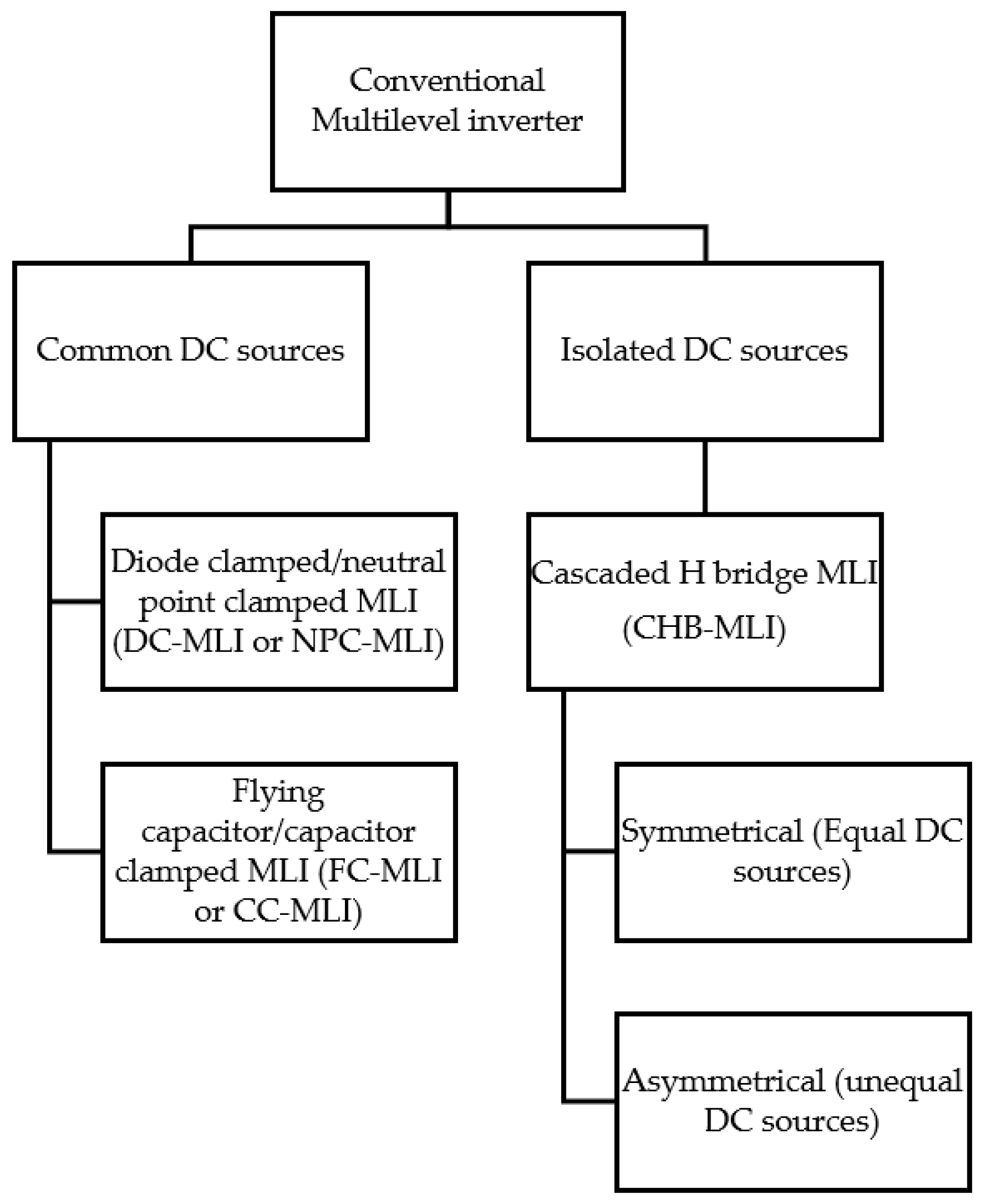
2. Conventional Multilevel Inverters
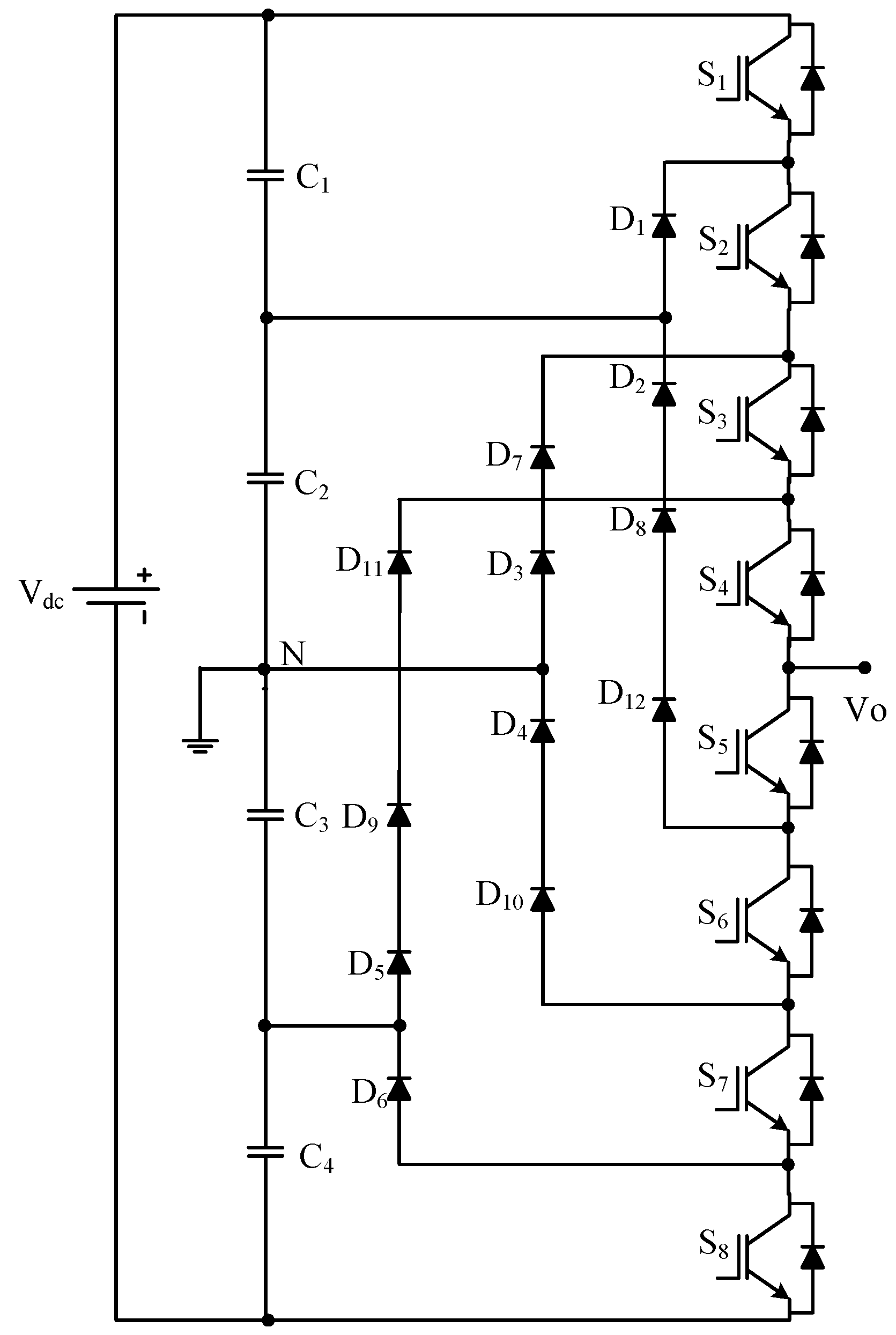
2.1. Diode-Clamped/Neutral-Point-Clamped Multilevel Inverter (DC-MLI)
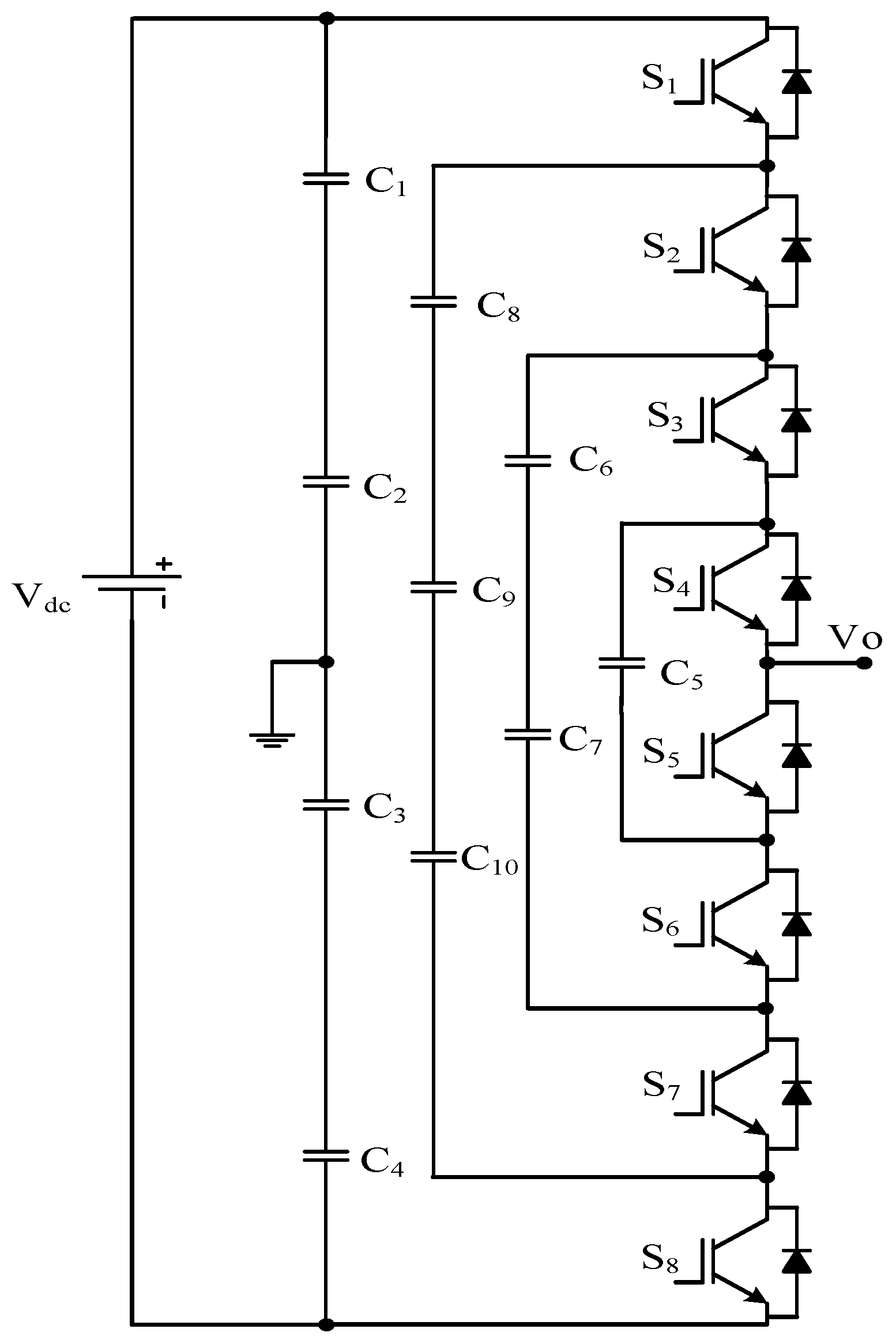
2.2. Capacitor Clamped/Flying Capacitor Multilevel Inverter
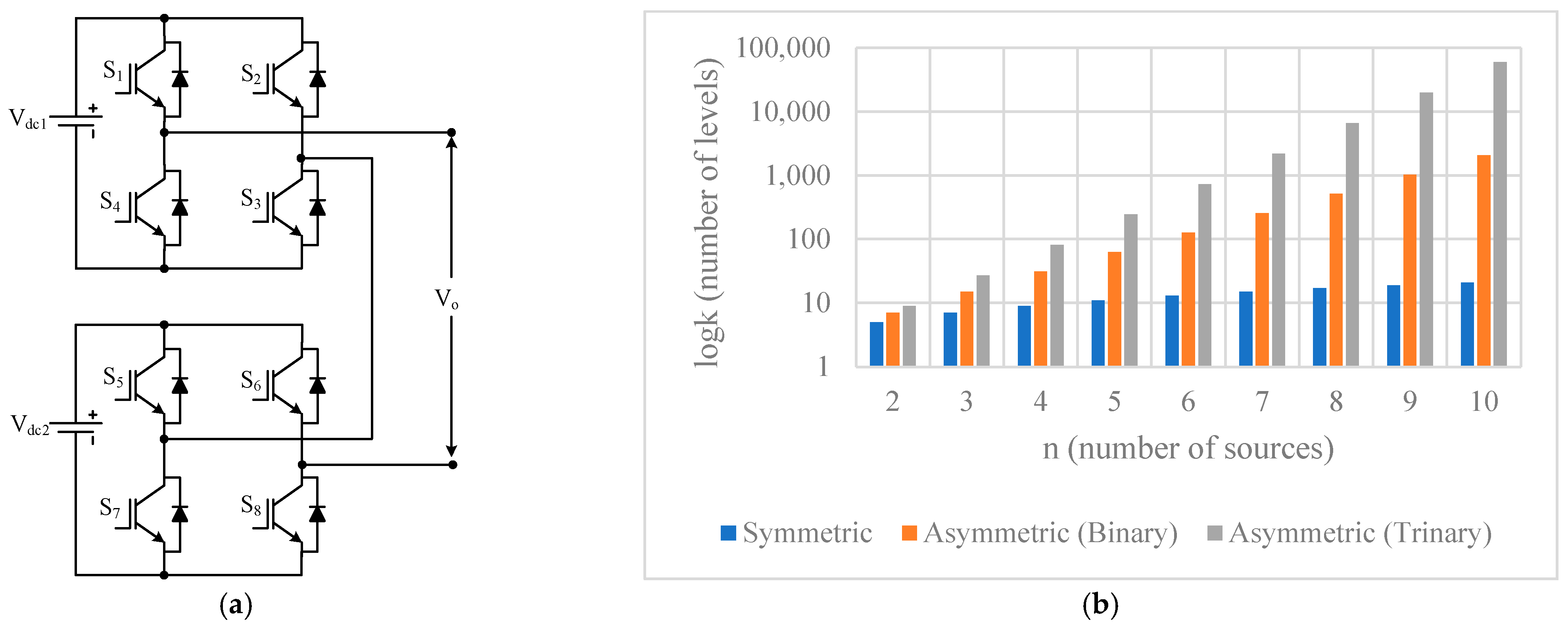
2.3. Cascaded H-Bridge Multilevel Inverter (CHB-MLI)
- Cascaded transformer;
- PWM inverter cascaded transformer;
- Forward converter cascaded transformer;
- Stacked inverter with cascaded transformer;
- Z-source cascaded transformer.
3. Reduced Device Count Multilevel Inverter Topologies
3.1. Cascaded Half-Bridge Multilevel Inverters (CHB-MLI)
3.2. Bidirectional Switch Multilevel Inverter
3.3. DC Switched Sources MLI
3.4. Switched Capacitor Multilevel Inverter
3.5. Developed H-Bridge Multilevel Inverters
3.6. Packed U-Cell Multilevel Inverter (PUCMLI)
3.7. Other Reduced Device Count Multilevel Inverter
4. Comparative Study of Reduced Device Count MLIs
5. Reduced Device Count Multilevel Inverters in Photovoltaic Systems
6. Conclusions
- ○
- Fault-tolerant operations;
- ○
- Integration with PV systems, wind-energy-conversion systems, fuel cells, etc.;
- ○
- Speed control of drives;
- ○
- Asymmetric operation such as natural, binary, and trinary progression;
- ○
- Cascaded and hybrid configurations;
- ○
- Implementation of modulation and control schemes.
Author Contributions
Funding
Data Availability Statement
Acknowledgments
Conflicts of Interest
References
- Bose, B.K. Global energy scenario and impact of power electronics in 21st century. IEEE Trans. Ind. Electron. 2013, 60, 2638–2651. [Google Scholar] [CrossRef]
- Wang, G.; Konstantinou, G.; Townsend, C.D.; Pou, J.; Vazquez, S.; Demetriades, G.D.; Agelidis, V.G. A review of power electronics for grid connection of utility-scale battery energy storage systems. IEEE Trans. Sustain. Energy 2016, 7, 1778–1790. [Google Scholar] [CrossRef]
- Hegazy, O.; Barrero, R.; Van Mierlo, J.; Lataire, P.; Omar, N.; Coosemans, T. An advanced power electronics interface for electric vehicles applications. IEEE Trans. Power Electron. 2013, 28, 5508–5521. [Google Scholar] [CrossRef]
- Sahito, A.A.; Halepoto, I.A.; Uqaili, M.A.; Memon, Z.A.; Larik, A.S.; Mahar, M.A. Analyzing the impacts of distributed generation integration on distribution network: A corridor towards smart grid implementation in Pakistan. Wirel. Pers. Commun. 2015, 85, 545–563. [Google Scholar] [CrossRef]
- Colak, I.; Kabalci, E.; Bayindir, R. Review of multilevel voltage source inverter topologies and control schemes. Energy Convers. Manag. 2011, 52, 1114–1128. [Google Scholar] [CrossRef]
- Gupta, K.K.; Ranjan, A.; Bhatnagar, P.; Sahu, L.K.; Jain, S. Multilevel inverter topologies with reduced device count: A review. IEEE Trans. Power Electron. 2016, 31, 135–151. [Google Scholar] [CrossRef]
- Ceglia, G.; Grau, V.; Guzman, V.; Sanchez, C.; Ibanez, F.; Walter, J.; Millan, A.; Gimenez, M.I. A new multilevel inverter topology. In Proceedings of the Fifth IEEE International Caracas Conference on Devices, Circuits and Systems, 2004, Punta Cana, Dominican Republic, 3–5 November 2004; IEEE: Piscataway, NJ, USA, 2004. [Google Scholar]
- Merahi, F.; Berkouk, E.M. Back-to-back five-level converters for wind energy conversion system with DC-bus imbalance minimization. Renew. Energy 2013, 60, 137–149. [Google Scholar] [CrossRef]
- Mekhilef, S.; Kadir, M.N.A. Novel vector control method for three-stage hybrid cascaded multilevel inverter. IEEE Trans. Ind. Electron. 2011, 58, 1339–1349. [Google Scholar] [CrossRef]
- Sumithira, T.; Kumar, A.N. Elimination of harmonics in multilevel inverters connected to solar photovoltaic systems using ANFIS: An experimental case study. J. Appl. Res. Technol. 2013, 11, 124–132. [Google Scholar] [CrossRef]
- Daher, S. Analysis, Design and Implementation of a High Efficiency Multilevel Converter for Renewable Energy Systems; Kassel University Press: Kassel, Germany, 2006. [Google Scholar]
- Singh, J.; Dahiya, R.; Saini, L.M. Recent research on transformer based single DC source multilevel inverter: A review. Renew. Sustain. Energy Rev. 2017, 82, 3207–3224. [Google Scholar] [CrossRef]
- Alishah, R.S.; Nazarpour, D.; Hosseini, S.H.; Sabahi, M. New hybrid structure for multilevel inverter with fewer number of components for high-voltage levels. IET Power Electron. 2014, 7, 96–104. [Google Scholar] [CrossRef]
- Babaei, E.; Dehqan, A.; Sabahi, M. A new topology for multilevel inverter considering its optimal structures. Electr. Power Syst. Res. 2013, 103, 145–156. [Google Scholar] [CrossRef]
- Babaei, E.; Kangarlu, M.F.; Mazgar, F.N. Symmetric and asymmetric multilevel inverter topologies with reduced switching devices. Electr. Power Syst. Res. 2012, 86, 122–130. [Google Scholar] [CrossRef]
- Babaei, E.; Hosseini, S.H. New cascaded multilevel inverter topology with minimum number of switches. Energy Convers. Manag. 2009, 50, 2761–2767. [Google Scholar] [CrossRef]
- Babaei, E.; Hosseini, S.; Gharehpetian, G.; Haque, M.T.; Sabahi, M. Reduction of dc voltage sources and switches in asymmetrical multilevel converters using a novel topology. Electr. Power Syst. Res. 2007, 77, 1073–1085. [Google Scholar] [CrossRef]
- Sonti, V.; Jain, S.; Bhattacharya, S. Analysis of the modulation strategy for the minimization of the leakage current in the PV grid-connected cascaded multilevel inverter. IEEE Trans. Power Electron. 2017, 32, 1156–1169. [Google Scholar] [CrossRef]
- Selvaraj, J.; Rahim, N.A. Multilevel inverter for grid-connected PV system employing digital PI controller. IEEE Trans. Ind. Electron. 2009, 56, 149–158. [Google Scholar] [CrossRef]
- Siddique, M.D.; Mekhilef, S.; Shah, N.M.; Sarwar, A.; Iqbal, A.; Tayyab, M.; Ansari, M.K. Low switching frequency based asymmetrical multilevel inverter topology with reduced switch count. IEEE Access 2019, 7, 86374–86383. [Google Scholar] [CrossRef]
- Bana, P.R.; Panda, K.P.; Naayagi, R.T.; Siano, P.; Panda, G. Recently developed reduced switch multilevel inverter for renewable energy integration and drives application: Topologies, comprehensive analysis and comparative evaluation. IEEE Access 2019, 7, 54888–54909. [Google Scholar] [CrossRef]
- Kanaujia, A.K.; Sanjiv, K. A Reduced Switch Count Hybrid Fifteen-level Inverter for an Open-End Winding Induction Motor (OEWIM) Drive. In Proceedings of the 2018 8th IEEE India International Conference on Power Electronics (IICPE), Jaipur, India, 13–15 December 2018; IEEE: Piscataway, NJ, USA, 2018. [Google Scholar]
- Pal, P.K.; Jana, K.C.; Siwakoti, Y.P.; Majumdar, S.; Blaabjerg, F. An active-neutral-point-clamped switched-capacitor multilevel inverter with quasi-resonant capacitor charging. IEEE Trans. Power Electron. 2022, 37, 14888–14901. [Google Scholar] [CrossRef]
- Elias MF, M.; Abd Rahim, N.; Rosli, N.F. A Three-Phase Hybrid Multilevel Inverter with Enhanced Pulse-Width Modulation Strategy. IEEE Trans. Power Electron. 2022, 38, 4714–4726. [Google Scholar] [CrossRef]
- Yaramasu, V.; Wu, B. Predictive control of a three-level boost converter and an NPC inverter for high-power PMSG-based medium voltage wind energy conversion systems. IEEE Trans. Power Electron. 2014, 29, 5308–5322. [Google Scholar] [CrossRef]
- Ozpineci, B.; Tolbert, L.M.; Su, G.J.; Du, Z. Optimum fuel cell utilization with multilevel DC-DC converters. In Proceedings of the Nineteenth Annual IEEE Applied Power Electronics Conference and Exposition, 2004—APEC’04, Anaheim, CA, USA, 22–26 February 2004; IEEE: Piscataway, NJ, USA, 2004. [Google Scholar]
- Stynski, S.; San-Sebastian, J.; Malinowski, M.; Etxeberria-Otadui, I. Analysis of multilevel PWM converter based on FLC modules for an AC traction application. In Proceedings of the 2009 IEEE International Conference on Industrial Technology, Churchill, VIC, Australia, 10–13 February 2009; IEEE: Piscataway, NJ, USA, 2009. [Google Scholar]
- Carpita, M.; Marchesoni, M.; Pellerin, M.; Moser, D. Multilevel converter for traction applications: Small-scale prototype tests results. IEEE Trans. Ind. Electron. 2008, 55, 2203–2212. [Google Scholar] [CrossRef]
- Etxeberria-Otadui, I. Analysis of a H-NPC topology for an AC traction front-end converter. In Proceedings of the 2008 13th International Power Electronics and Motion Control Conference, Poznan, Poland, 1–3 September 2008; IEEE: Piscataway, NJ, USA, 2008. [Google Scholar]
- Malla, J.M.R.; Malla, S.G. Five level parallel inverter for DTC-SVM of induction motor. WSEAS Trans. Power Syst. 2010, 5, 273–286. [Google Scholar]
- Khoucha, F.; Lagoun, S.M.; Marouani, K.; Kheloui, A.; Benbouzid, M.E.H. Hybrid cascaded H-bridge multilevel-inverter induction-motor- drive direct torque control for automotive applications. IEEE Trans. Ind. Electron. 2010, 57, 892–899. [Google Scholar] [CrossRef]
- Panda, A.K.; Patnaik, S.S. Analysis of cascaded multilevel inverters for active harmonic filtering in distribution networks. Int. J. Electr. Power Energy Syst. 2015, 66, 216–226. [Google Scholar] [CrossRef]
- Lada, M.Y.; Mohamad, S.S.; Gani, J.A.M.; Nawawi, M.R.M.; Kim, G.C. Reduction of harmonic using single phase shunt active power filter based on instantaneous power theory for cascaded multilevel inverter. In Proceedings of the 2016 IEEE International Conference on Power and Energy (PECon), Melaka, Malaysia, 28–29 November 2016; IEEE: Piscataway, NJ, USA, 2016. [Google Scholar]
- Takasaki, M.; Miura, Y.; Ise, T. Wireless power transfer system for gate power supplies of modular multilevel converters. In Proceedings of the 2016 IEEE 8th International Power Electronics and Motion Control Conference (IPEMC-ECCE Asia), Hefei, China, 22–26 May 2016; IEEE: Piscataway, NJ, USA, 2016. [Google Scholar]
- Wang, Y.; Marquardt, R. Future HVDC-grids employing modular multilevel converters and hybrid DC-breakers. In Proceedings of the 2013 15th European Conference on Power Electronics and Applications (EPE), Lille, France, 2–6 September 2013; IEEE: Piscataway, NJ, USA, 2013. [Google Scholar]
- Prieto-Araujo, E.; Junyent-Ferré, A.; Collados-Rodríguez, C.; Clariana-Colet, G.; Gomis-Bellmunt, O. Control design of Modular Multilevel Converters in normal and AC fault conditions for HVDC grids. Electr. Power Syst. Res. 2017, 152, 424–437. [Google Scholar] [CrossRef]
- Zheng, Z.; Wang, K.; Xu, L.; Li, Y. A hybrid cascaded multilevel converter for battery energy management applied in electric vehicles. IEEE Trans. Power Electron. 2014, 29, 3537–3546. [Google Scholar] [CrossRef]
- Gaigowal, S.R.; Renge, M. Some studies of Distributed Series FACTS Controller to control active power flow through Transmission Line. In Proceedings of the 2013 International Conference on Power, Energy and Control (ICPEC), Dindigul, India, 6–8 February 2013; IEEE: Piscataway, NJ, USA, 2013. [Google Scholar]
- Kakkar, V.; Agarwal, N. Recent trends on FACTS and D-FACTS. In Proceedings of the 2010 Modern Electric Power Systems, Wroclaw, Poland, 20–22 September 2010; IEEE: Piscataway, NJ, USA, 2010. [Google Scholar]
- Sirisukprasert, S.; Liu, Y.; Xu, Z.; Zhang, B.; Zhou, X.; Hawley, J.; Huang, A.Q. Power stage and control design for the ETO-based cascaded- multilevel converter for FACTS applications. In Proceedings of the 4th International Power Electronics and Motion Control Conference, 2004—IPEMC 2004, Xi’an, China, 14–16 August 2004; IEEE: Piscataway, NJ, USA, 2004. [Google Scholar]
- Rohner, S.; Bernet, S.; Hiller, M.; Sommer, R. Modulation, losses, and semiconductor requirements of modular multilevel converters. IEEE Trans. Ind. Electron. 2010, 57, 2633–2642. [Google Scholar] [CrossRef]
- Zhang, L.; Sun, K.; Feng, L.; Wu, H.; Xing, Y. A family of neutral point clamped full-bridge topologies for transformerless photovoltaic grid-tied inverters. IEEE Trans. Power Electron. 2013, 28, 730–739. [Google Scholar] [CrossRef]
- Abu-Rub, H.; Holtz, J.; Rodriguez, J.; Baoming, G. Medium-voltage multilevel converters—State of the art, challenges, and requirements in industrial applications. IEEE Trans. Ind. Electron. 2010, 57, 2581–2596. [Google Scholar] [CrossRef]
- Latran, M.B.; Teke, A. Investigation of multilevel multifunctional grid connected inverter topologies and control strategies used in photovoltaic systems. Renew. Sustain. Energy Rev. 2015, 42, 361–376. [Google Scholar] [CrossRef]
- Rashid, M.H. Power Electronics Handbook; Butterworth-Heinemann: Oxford, UK, 2017. [Google Scholar]
- Yuan, X.; Barbi, I. Fundamentals of a new diode clamping multilevel inverter. IEEE Trans. Power Electron. 2000, 15, 711–718. [Google Scholar] [CrossRef]
- Vishvakarma, R.P.; Singh, S.; Shukla, T. Multilevel inverters and its control strategies: A comprehensive review. In Proceedings of the 2012 2nd International Conference on Power, Control and Embedded Systems, Allahabad, India, 17–19 December 2012; IEEE: Piscataway, NJ, USA, 2012. [Google Scholar]
- Kala, P.; Arora, S. A comprehensive study of classical and hybrid multilevel inverter topologies for renewable energy applications. Renew. Sustain. Energy Rev. 2017, 76, 905–931. [Google Scholar] [CrossRef]
- Villanueva, E.; Correa, P.; Rodriguez, J.; Pacas, M. Control of a single-phase cascaded H-bridge multilevel inverter for grid-connected photovoltaic systems. IEEE Trans. Ind. Electron. 2009, 56, 4399–4406. [Google Scholar] [CrossRef]
- Alonso, O.; Sanchis, P.; Gubia, E.; Marroyo, L. Cascaded H-bridge multilevel converter for grid connected photovoltaic generators with independent maximum power point tracking of each solar array. In Proceedings of the IEEE 34th Annual Conference on Power Electronics Specialist, 2003—PESC’03, Acapulco, Mexico, 15–19 June 2003; IEEE: Piscataway, NJ, USA, 2003. [Google Scholar]
- Cortés, P.; Wilson, A.; Kouro, S.; Rodriguez, J.; Abu-Rub, H. Model predictive control of multilevel cascaded H-bridge inverters. IEEE Trans. Ind. Electron. 2010, 57, 2691–2699. [Google Scholar] [CrossRef]
- Corzine, K.; Familiant, Y. A new cascaded multilevel H-bridge drive. IEEE Trans. Power Electron. 2002, 17, 125–131. [Google Scholar] [CrossRef]
- Song, W.; Huang, A.Q. Fault-tolerant design and control strategy for cascaded H- bridge multilevel converter-based STATCOM. IEEE Trans. Ind. Electron. 2010, 57, 2700–2708. [Google Scholar] [CrossRef]
- Wei, S.; Wu, B.; Li, F.; Sun, X. Control method for cascaded H-bridge multilevel inverter with faulty power cells. In Proceedings of the Eighteenth Annual IEEE Applied Power Electronics Conference and Exposition, 2003—APEC’03, Miami Beach, FL, USA, 9–13 February 2003; IEEE: Piscataway, NJ, USA, 2003. [Google Scholar]
- Barrena, J.A.; Marroyo, L.; Vidal, M.R.; Apraiz, J.R.T. Individual voltage balancing strategy for PWM cascaded H-bridge converter-based STATCOM. IEEE Trans. Ind. Electron. 2008, 55, 21–29. [Google Scholar] [CrossRef]
- Franquelo, L.G.; Rodriguez, J.; Leon, J.I.; Kouro, S.; Portillo, R.; Prats, M.A. The age of multilevel converters arrives. IEEE Ind. Electron. Mag. 2008, 2, 28–39. [Google Scholar] [CrossRef]
- Deng, F.; Tian, Y.; Zhu, R.; Chen, Z. Fault-tolerant approach for modular multilevel converters under submodule faults. IEEE Trans. Ind. Electron. 2016, 63, 7253–7263. [Google Scholar] [CrossRef]
- Maharjan, L.; Inoue, S.; Akagi, H.; Asakura, J. State-of-charge (SOC)-balancing control of a battery energy storage system based on a cascade PWM converter. IEEE Trans. Power Electron. 2009, 24, 1628–1636. [Google Scholar] [CrossRef]
- Ge, B.; Liu, Y.; Abu-Rub, H.; Peng, F.Z. State-of-Charge Balancing Control for a Battery-Energy-Stored Quasi- Z-Source Cascaded-Multilevel-Inverter-Based Photovoltaic Power System. IEEE Trans. Ind. Electron. 2018, 65, 2268–2279. [Google Scholar] [CrossRef]
- Kotb, K.M.; Hassan, A.E.-W.; Rashad, E.M. Simplified sinusoidal pulse width modulation for cascaded half-bridge multilevel inverter. In Proceedings of the 2016 Eighteenth International Middle East Power Systems Conference (MEPCON), Cairo, Egypt, 27–29 December 2016; IEEE: Piscataway, NJ, USA, 2016. [Google Scholar]
- Suresh, Y.; Venkataramanaiah, J.; Panda, A.K.; Dhanamjayulu, C.; Venugopal, P. Investigation on cascade multilevel inverter with symmetric, asymmetric, hybrid and multi-cell configurations. Ain Shams Eng. J. 2017, 8, 263–276. [Google Scholar] [CrossRef]
- Shahir, F.M.; Babaei, E. 16-level basic topology for cascaded multilevel inverters with reduced number of components. In Proceedings of the IECON 2016 42nd Annual Conference of the IEEE Industrial Electronics Society, Florence, Italy, 23–26 October 2016; IEEE: Piscataway, NJ, USA, 2016. [Google Scholar]
- Karaarslan, K.; Arifoglu, B.; Beser, E.; Camur, S. Half-bridge Cascaded Multilevel Inverter Based Series Active Power Filter. J. Power Electron. 2017, 17, 777–787. [Google Scholar] [CrossRef]
- Ramani, K.; Sathik, M.A.J.; Sivakumar, S. A new symmetric multilevel inverter topology using single and double source sub-multilevel inverters. J. Power Electron. 2015, 15, 96–105. [Google Scholar] [CrossRef]
- Al-Judi, A.; Bierk, H.; Nowicki, E. A modified cascaded multilevel inverter with reduced switch count employing bypass diodes. In Proceedings of the 2009 IEEE Vehicle Power and Propulsion Conference, Dearborn, MI, USA, 7–10 September 2009; IEEE: Piscataway, NJ, USA, 2009. [Google Scholar]
- Ahmed, M.; Sheir, A.; Orabi, M. Asymmetric cascaded half-bridge multilevel inverter without polarity changer. Alex. Eng. J. 2017, 57, 2415–2426. [Google Scholar] [CrossRef]
- Batschauer, A.L.; Mussa, S.A.; Heldwein, M.L. Three-phase hybrid multilevel inverter based on half-bridge modules. IEEE Trans. Ind. Electron. 2012, 59, 668–678. [Google Scholar] [CrossRef]
- Konstantinou, G.S.; Agelidis, V.G. Performance evaluation of half-bridge cascaded multilevel converters operated with multicarrier sinusoidal PWM techniques. In Proceedings of the 2009 4th IEEE Conference on Industrial Electronics and Applications, Xi’an, China, 25–27 May 2009; IEEE: Piscataway, NJ, USA, 2009. [Google Scholar]
- Vahedi, H.; Al-Haddad, K. Half-bridge based multilevel inverter generating higher voltage and power. In Proceedings of the 2013 IEEE Electrical Power & Energy Conference, Halifax, NS, Canada, 21–23 August 2013; IEEE: Piscataway, NJ, USA, 2013. [Google Scholar]
- Luo, H.X.; Wang, L.; Wu, Q.H.; Ma, X.X. One cycle control for a half-bridge cascaded multilevel inverter. In Proceedings of the 2016 IEEE Innovative Smart Grid Technologies-Asia (ISGT-Asia), Melbourne, VIC, Australia, 28 November–1 December 2016; IEEE: Piscataway, NJ, USA, 2016. [Google Scholar]
- Gupta, K.K.; Jain, S. A novel multilevel inverter based on switched DC sources. IEEE Trans. Ind. Electron. 2014, 61, 3269–3278. [Google Scholar] [CrossRef]
- Ceglia, G.; Guzman, V.; Sanchez, C.; Ibanez, F.; Walter, J.; Gimenez, M. A new simplified multilevel inverter topology for DC–AC conversion. IEEE Trans. Power Electron. 2006, 21, 1311–1319. [Google Scholar] [CrossRef]
- Rahim, N.A.; Chaniago, K.; Selvaraj, J. Single-phase seven-level grid-connected inverter for photovoltaic system. IEEE Trans. Ind. Electron. 2011, 58, 2435–2443. [Google Scholar] [CrossRef]
- Wu, F.; Duan, J.; Feng, F. Modified single-carrier multilevel sinusoidal pulse width modulation for asymmetrical insulated gate bipolar transistor-clamped grid-connected inverter. IET Power Electron. 2015, 8, 1531–1541. [Google Scholar] [CrossRef]
- Rahim, N.A.; Elias, M.F.M.; Hew, W.P. Transistor-clamped H-bridge based cascaded multilevel inverter with new method of capacitor voltage balancing. IEEE Trans. Ind. Electron. 2013, 60, 2943–2956. [Google Scholar]
- Gautam, S.P.; Gupta, S.; Kumar, L. Reliability improvement of transistor clamped H-bridge-based cascaded multilevel inverter. IET Power Electron. 2017, 10, 770–781. [Google Scholar] [CrossRef]
- Choudhary, R.; Sarkar, I. Single phase five level Transistor Clamped inverter with multi-band hysteresis current control. In Proceedings of the 2016 IEEE 6th International Conference on Power Systems (ICPS), New Delhi, India, 4–6 March 2016; IEEE: Piscataway, NJ, USA, 2016. [Google Scholar]
- Halim, W.A.; Rahim, N.A.; Azri, M. Generalized selective harmonic elimination modulation for transistor-clamped H-bridge multilevel inverter. J. Power Electron. 2015, 15, 964–973. [Google Scholar] [CrossRef][Green Version]
- Elias, M.F.M.; Rahim, N.A.; Ping, H.W.; Uddin, M.N. Asymmetrical cascaded multilevel inverter based on transistor- clamped H-bridge power cell. IEEE Trans. Ind. Appl. 2014, 50, 4281–4288. [Google Scholar] [CrossRef]
- Ebrahimi, J.; Babaei, E.; Gharehpetian, G.B. A new multilevel converter topology with reduced number of power electronic components. IEEE Trans. Ind. Electron. 2012, 59, 655–667. [Google Scholar] [CrossRef]
- Babaei, E. Optimal topologies for cascaded sub-multilevel converters. J. Power Electron. 2010, 10, 251–261. [Google Scholar] [CrossRef]
- Klumpner, C.; Blaabjerg, F. Using reverse-blocking IGBTs in power converters for adjustable-speed drives. IEEE Trans. Ind. Appl. 2006, 42, 807–816. [Google Scholar] [CrossRef]
- Hinago, Y.; Koizumi, H. A single-phase multilevel inverter using switched series/parallel dc voltage sources. IEEE Trans. Ind. Electron. 2010, 57, 2643–2650. [Google Scholar] [CrossRef]
- Fong, Y.C.; Ye, Y.; Raman, S.R.; Cheng, K.W. A hybrid multilevel inverter employing series-parallel switched- capacitor unit. In Proceedings of the 2017 IEEE Applied Power Electronics Conference and Exposition (APEC), Tampa, FL, USA, 26–30 March 2017; IEEE: Piscataway, NJ, USA, 2017. [Google Scholar]
- Zamiri, E.; Vosoughi, N.; Hosseini, S.H.; Barzegarkhoo, R.; Sabahi, M. A new cascaded switched-capacitor multilevel inverter based on improved series–parallel conversion with less number of components. IEEE Trans. Ind. Electron. 2016, 63, 3582–3594. [Google Scholar] [CrossRef]
- Barzegarkhoo, R.; Moradzadeh, M.; Zamiri, E.; Kojabadi, H.M.; Blaabjerg, F. A new boost switched-capacitor multilevel converter with reduced circuit devices. IEEE Trans. Power Electron. 2018, 33, 6738–6754. [Google Scholar] [CrossRef]
- Lee, S. Single-Stage Switched-Capacitor Module (S3CM) Topology for Cascaded Multilevel Inverter. IEEE Trans. Power Electron. 2018, 33, 8204–8207. [Google Scholar] [CrossRef]
- Barzegarkhoo, R.; Kojabadi, H.M.; Zamiry, E.; Vosoughi, N.; Chang, L. Generalized structure for a single phase switched-capacitor multilevel inverter using a new multiple dc link producer with reduced number of switches. IEEE Trans. Power Electron. 2016, 31, 5604–5617. [Google Scholar] [CrossRef]
- Kanimozhi, M.; Geetha, P. A new boost switched capacitor multilevel inverter using different multi carrier PWM techniques. In Proceedings of the 2014 International Conference on Circuits, Power and Computing Technologies [ICCPCT-2014], Nagercoil, India, 20–21 March 2014; IEEE: Piscataway, NJ, USA, 2014. [Google Scholar]
- Raman, S.R.; Cheng, K.W.E.; Ye, Y. Multi-input switched-capacitor multilevel inverter for high-frequency ac power distribution. IEEE Trans. Power Electron. 2018, 33, 5937–5948. [Google Scholar] [CrossRef]
- Zeng, J.; Wu, J.; Liu, J.; Guo, H. A Quasi-Resonant Switched-Capacitor Multilevel Inverter with Self-Voltage Balancing for Single-Phase High-Frequency AC Microgrids. IEEE Trans. Ind. Inform. 2017, 13, 2669–2679. [Google Scholar] [CrossRef]
- Taghvaie, A.; Adabi, J.; Rezanejad, M. A Multilevel Inverter Structure Based on a Combination of Switched-Capacitors and DC Sources. IEEE Trans. Ind. Inform. 2017, 13, 2162–2171. [Google Scholar] [CrossRef]
- Taghvaie, A.; Adabi, J.; Rezanejad, M. A self-balanced step-up multilevel inverter based on switched-capacitor structure. IEEE Trans. Power Electron. 2018, 33, 199–209. [Google Scholar] [CrossRef]
- Cao, D.; Peng, F.Z. Zero-current-switching multilevel modular switched-capacitor DC–DC converter. IEEE Trans. Ind. Appl. 2010, 46, 2536–2544. [Google Scholar] [CrossRef]
- Sandeep, N.; Yaragatti, U.R. A Switched-Capacitor-Based Multilevel Inverter Topology with Reduced Components. IEEE Trans. Power Electron. 2017, 33, 5538–5542. [Google Scholar] [CrossRef]
- Babaei, E.; Gowgani, S.S. Hybrid multilevel inverter using switched capacitor units. IEEE Trans. Ind. Electron. 2014, 61, 4614–4621. [Google Scholar] [CrossRef]
- Babaei, E.; Alilu, S.; Laali, S. A new general topology for cascaded multilevel inverters with reduced number of components based on developed H-bridge. IEEE Trans. Ind. Electron. 2014, 61, 3932–3939. [Google Scholar] [CrossRef]
- Babaei, E.; Laali, S. Optimum structures of proposed new cascaded multilevel inverter with reduced number of components. IEEE Trans. Ind. Electron. 2015, 62, 6887–6895. [Google Scholar] [CrossRef]
- Sarbanzadeh, M.; Babaei, E.; Hosseinzadeh, M.A.; Cecati, C. A new sub-multilevel inverter with reduced number of components. In Proceedings of the IECON 2016 42nd Annual Conference of the IEEE Industrial Electronics Society, Florence, Italy, 23–26 October 2016; IEEE: Piscataway, NJ, USA, 2016. [Google Scholar]
- Alishah, R.S.; Hosseini, S.H.; Babaei, E.; Sabahi, M. Optimal design of new cascaded switch-ladder multilevel inverter structure. IEEE Trans. Ind. Electron. 2017, 64, 2072–2080. [Google Scholar] [CrossRef]
- Lee, S.S.; Sidorov, M.; Idris, N.R.N.; Heng, Y.E. A Symmetrical Cascaded Compact-Module Multilevel Inverter (CCM-MLI) With Pulsewidth Modulation. IEEE Trans. Ind. Electron. 2018, 65, 4631–4639. [Google Scholar] [CrossRef]
- Ounejjar, Y.; Al-Haddad, K.; Gregoire, L.-A. Packed U cells multilevel converter topology: Theoretical study and experimental validation. IEEE Trans. Ind. Electron. 2011, 58, 1294–1306. [Google Scholar] [CrossRef]
- Babadi, A.N.; Salari, O.; Mojibian, M.J.; Bina, M.T. Modified Multilevel Inverters with Reduced Structures Based on PackedU-Cell. IEEE J. Emerg. Sel. Top. Power Electron. 2018, 6, 874–887. [Google Scholar] [CrossRef]
- Ounejjar, Y.; Al-Haddad, K.; Dessaint, L.A. A novel six-band hysteresis control for the packed U cells seven-level converter: Experimental validation. IEEE Trans. Ind. Electron. 2012, 59, 3808–3816. [Google Scholar] [CrossRef]
- Metri, J.I.; Vahedi, H.; Kanaan, H.Y.; Al-Haddad, K. Real-time implementation of model-predictive control on seven-level packed U-cell inverter. IEEE Trans. Ind. Electron. 2016, 63, 4180–4186. [Google Scholar] [CrossRef]
- Oskuee, M.R.J.; Karimi, M.; Ravadanegh, S.N.; Gharehpetian, G.B. An innovative scheme of symmetric multilevel voltage source inverter with lower number of circuit devices. IEEE Trans. Ind. Electron. 2015, 62, 6965–6973. [Google Scholar] [CrossRef]
- Samadaei, E.; Sheikholeslami, A.; Gholamian, S.A.; Adabi, J. A square T-type (ST-Type) module for asymmetrical multilevel inverters. IEEE Trans. Power Electron. 2018, 33, 987–996. [Google Scholar] [CrossRef]
- Siddique, M.D.; Iqbal, A.; Sarwar, A.; Mekhilef, S. Analysis and implementation of a new asymmetric double H-bridge multilevel inverter. Int. J. Circuit Theory Appl. 2021, 49, 4012–4026. [Google Scholar] [CrossRef]
- Salem, M.; Richelli, A.; Yahya, K.; Hamidi, M.N.; Ang, T.-Z.; Alhamrouni, I. A Comprehensive Review on Multilevel Inverters for Grid-Tied System Applications. Energies 2022, 15, 6315. [Google Scholar] [CrossRef]
- Hammami, M.; Grandi, G. A single-phase multilevel PV generation system with an improved ripple correlation control MPPT algorithm. Energies 2017, 10, 2037. [Google Scholar] [CrossRef]
- Rajalakshmi, S.; Rangarajan, P. Investigation of modified multilevel inverter topology for PV system. Microprocess. Microsyst. 2019, 71, 102870. [Google Scholar] [CrossRef]
- Bana, P.R.; Panda, K.P.; Panda, G. Power quality performance evaluation of multilevel inverter with reduced switching devices and minimum standing voltage. IEEE Trans. Ind. Inform. 2019, 16, 5009–5022. [Google Scholar] [CrossRef]
- Ponnusamy, P.; Sivaraman, P.; Almakhles, D.J.; Padmanaban, S.; Leonowicz, Z.; Alagu, M.; Ali, J.S.M. A new multilevel inverter topology with reduced power components for domestic solar PV applications. IEEE Access 2020, 8, 187483–187497. [Google Scholar] [CrossRef]
- Pourfaraj, A.; Monfared, M.; Heydari-doostabad, H. Single-phase dual-mode interleaved multilevel inverter for PV applications. IEEE Trans. Ind. Electron. 2019, 67, 2905–2915. [Google Scholar] [CrossRef]
- Cm, N.M.; Vineeth, K.; Kurmar, S.S.; Jayaprakash, P. An Improved H- Bridge Multilevel Inverter-Based Multi-Objective Photovoltaic Power Conversion System. IEEE Trans. Ind. Appl. 2021, 57, 6339–6349. [Google Scholar]
- Bhukya, M.N.; Kota, V.R.; Depuru, S.R. A simple, efficient, and novel standalone photovoltaic inverter configuration with reduced harmonic distortion. IEEE Access 2019, 7, 43831–43845. [Google Scholar] [CrossRef]
- Kurian, G.M.; Jeyanthy, P.A.; Devaraj, D. FPGA implementation of FLC-MPPT for harmonics reduction in sustainable photovoltaic system. Sustain. Energy Technol. Assess. 2022, 52, 102192. [Google Scholar]
- Prabaharan, N.; Palanisamy, K. Analysis and integration of multilevel inverter configuration with boost converters in a photovoltaic system. Energy Convers. Manag. 2016, 128, 327–342. [Google Scholar] [CrossRef]
- Bana, P.R.; Panda, K.P.; Padmanaban, S.; Mihet-Popa, L.; Panda, G.; Wu, J. Closed-loop control and performance evaluation of reduced part count multilevel inverter interfacing grid-connected PV system. IEEE Access 2020, 8, 75691–75701. [Google Scholar] [CrossRef]
- Janardhan, K.; Mittal, A.; Ojha, A. Performance investigation of stand-alone solar photovoltaic system with single phase micro multilevel inverter. Energy Rep. 2020, 6, 2044–2055. [Google Scholar] [CrossRef]
- Ramesh, A.; Sait, H.H. An approach towards selective harmonic elimination switching pattern of cascade switched capacitor twenty nine-level inverter using artificial bee colony algorithm. Microprocess. Microsyst. 2020, 79, 103292. [Google Scholar] [CrossRef]
- Gopal, Y.; Kumar, Y.N.V.; Kumari, A.; Prakash, O.; Chowdhury, S.; Almehizia, A.A. Reduced Device Count for Self Balancing Switched-Capacitor Multilevel Inverter Integration with Renewable Energy Source. Sustainability 2023, 15, 8000. [Google Scholar] [CrossRef]
- El Ouardi, H.; El Gadari, A.; Mokhlis, M.; Ounejjar, Y.; Bejjit, L.; Al-Haddad, K. A Novel MPPT Technique Based on Combination between the Incremental Conductance and Hysteresis Control Applied in a Standalone PV System. Eng 2023, 4, 964–976. [Google Scholar] [CrossRef]
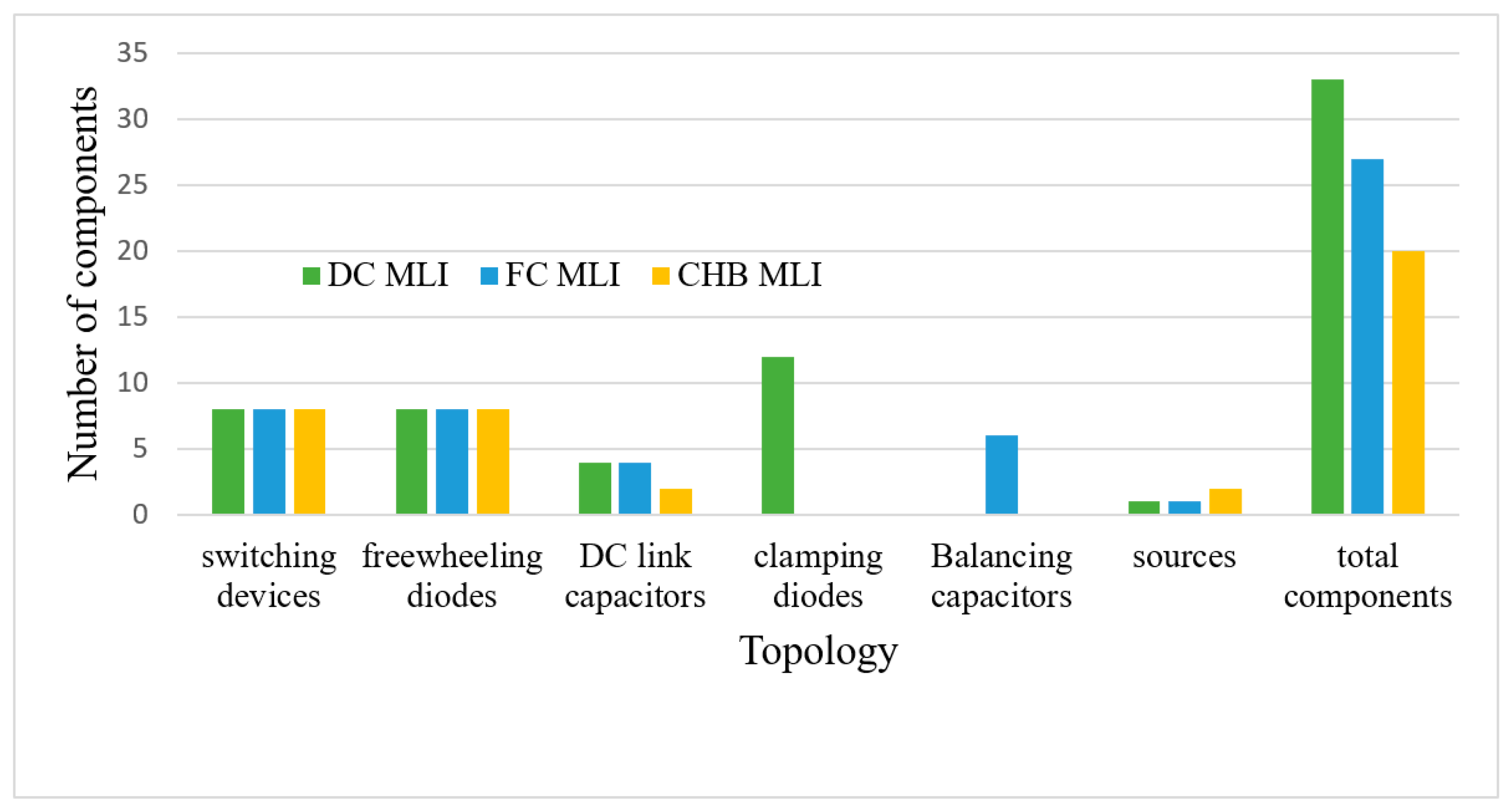
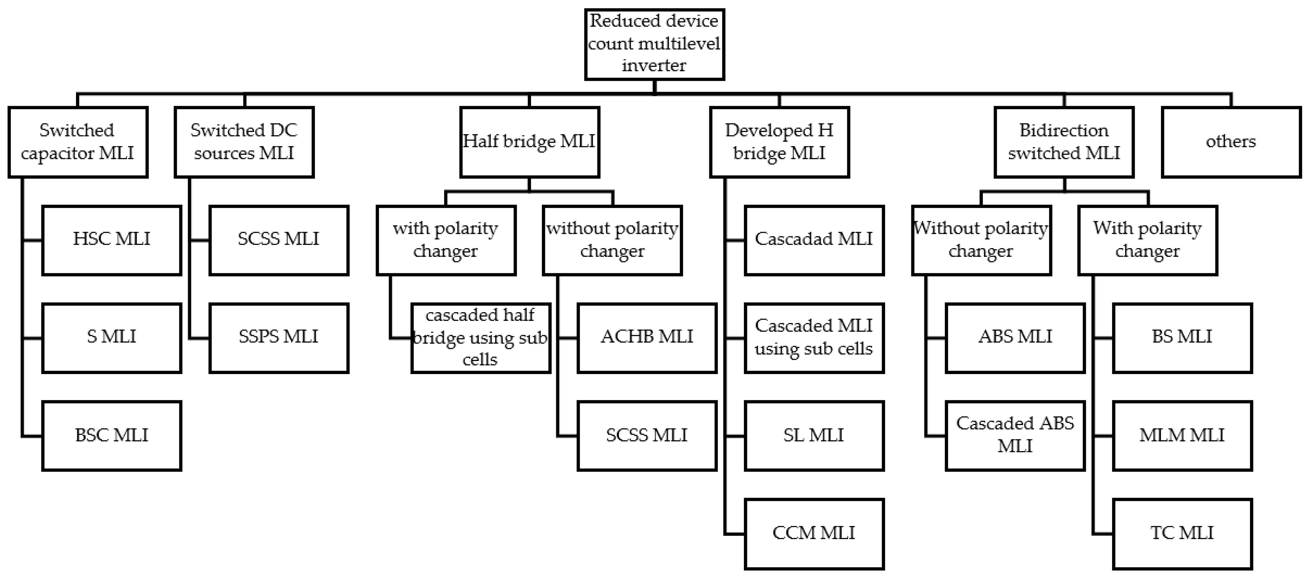
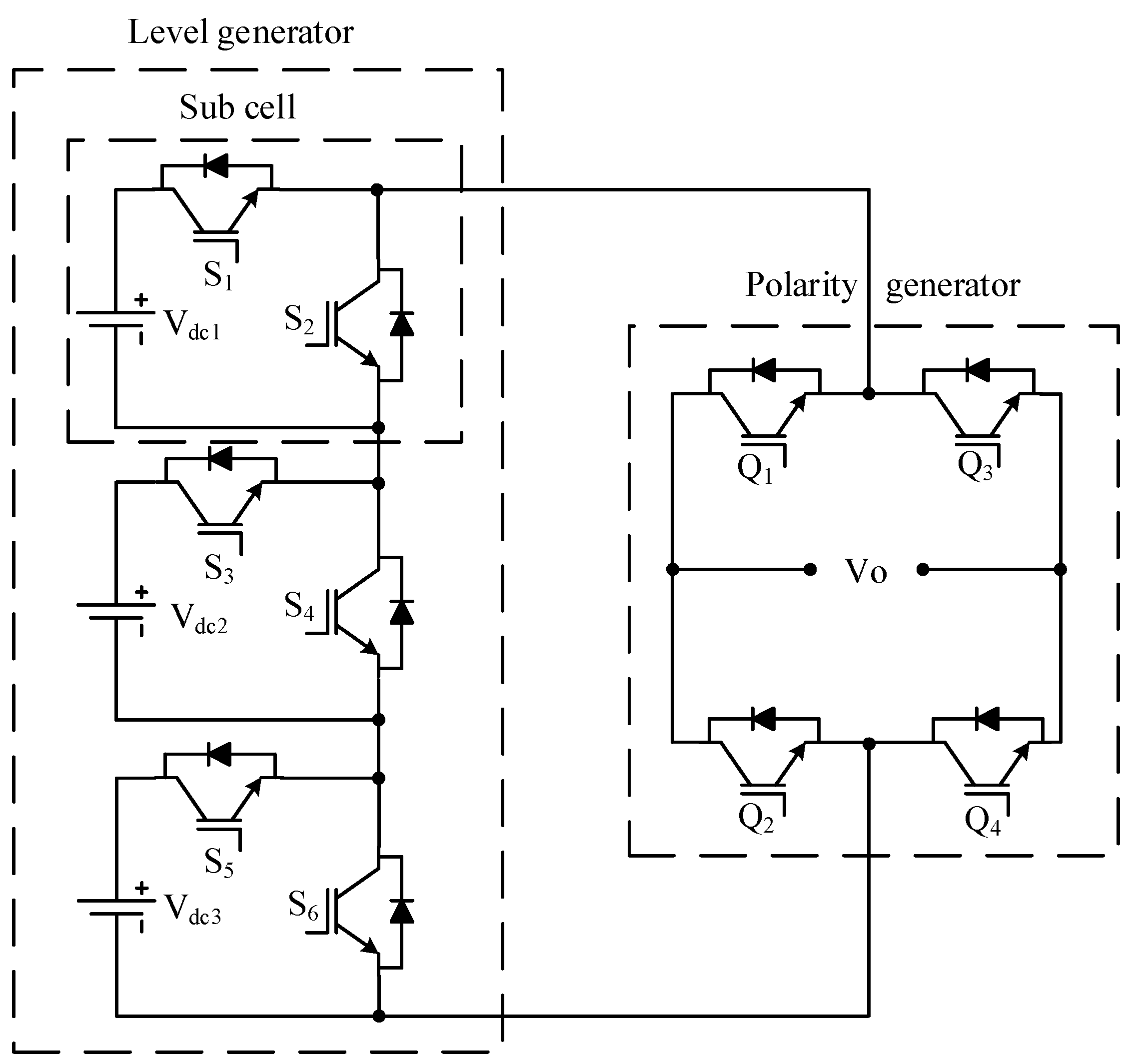
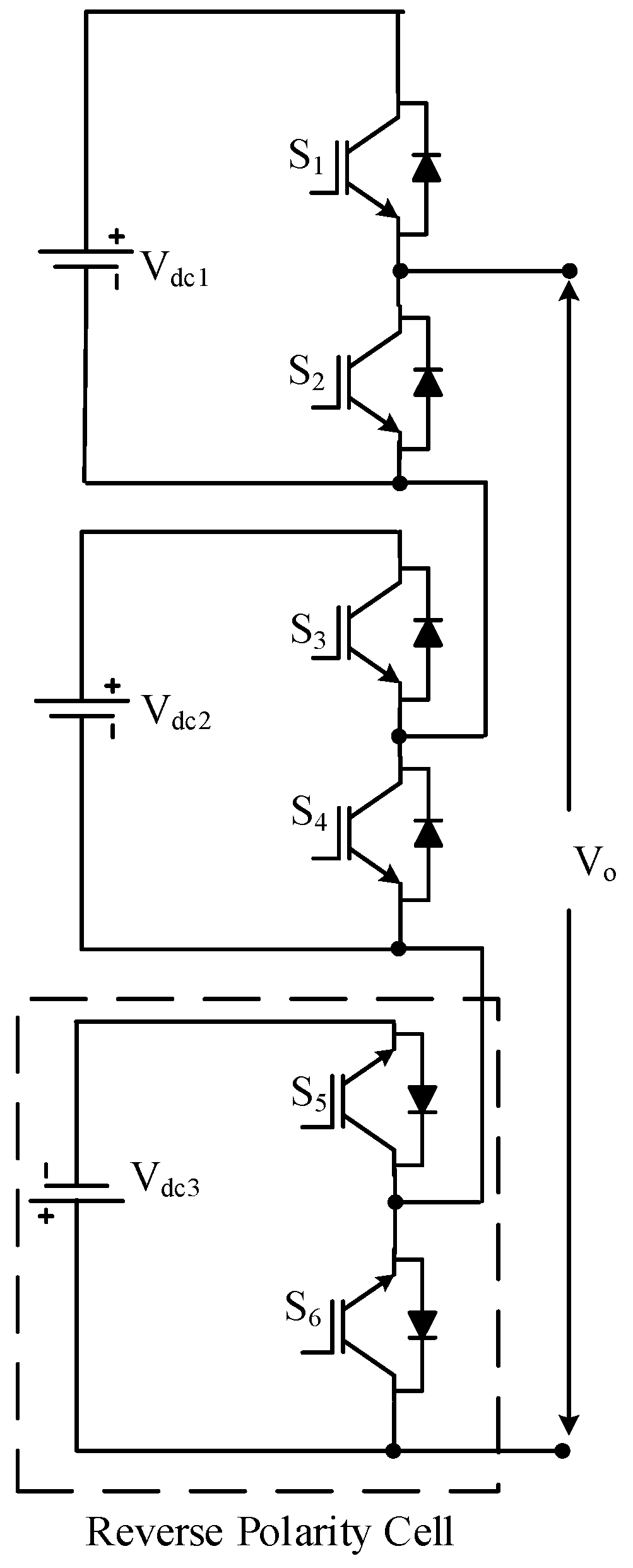
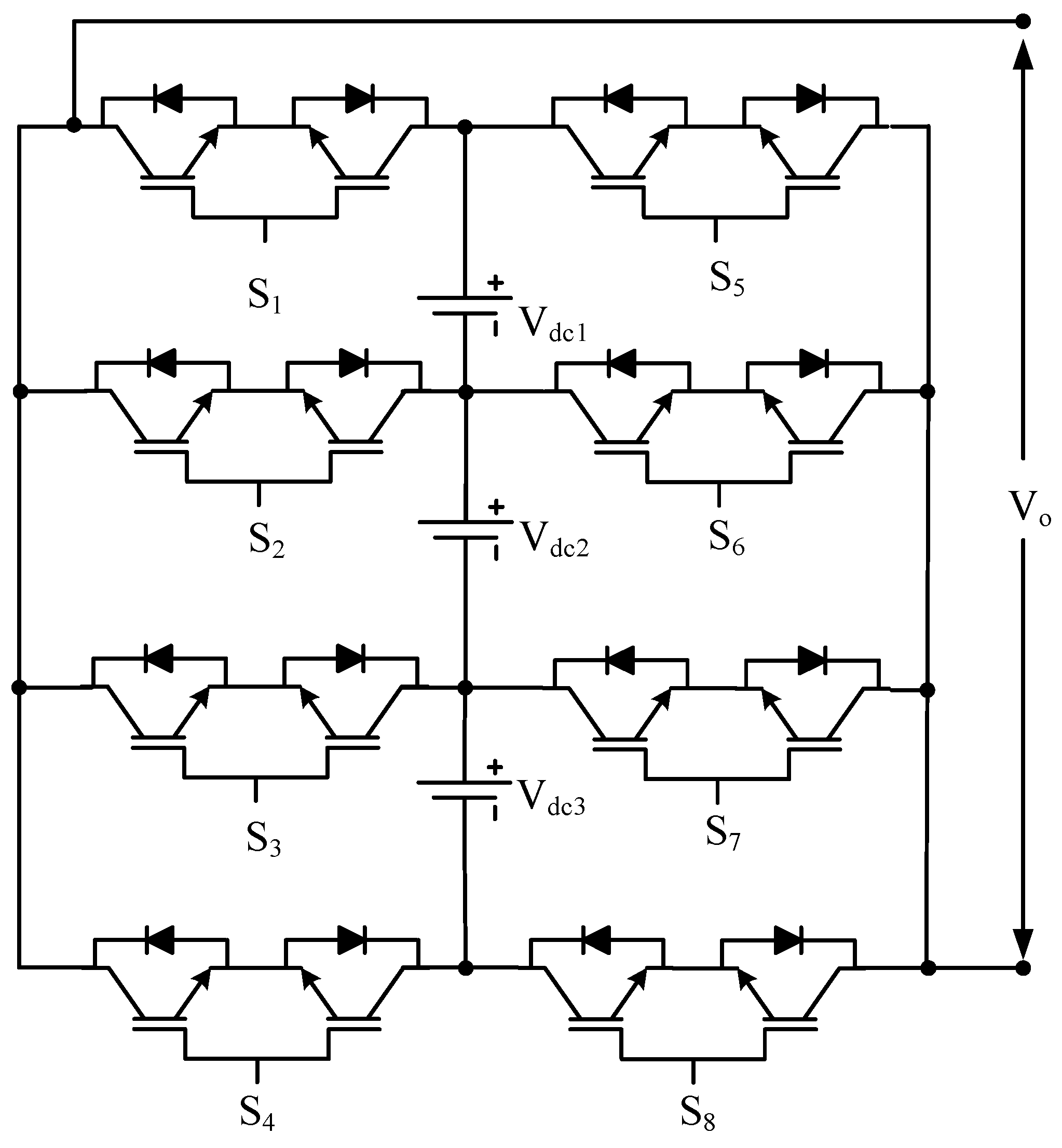
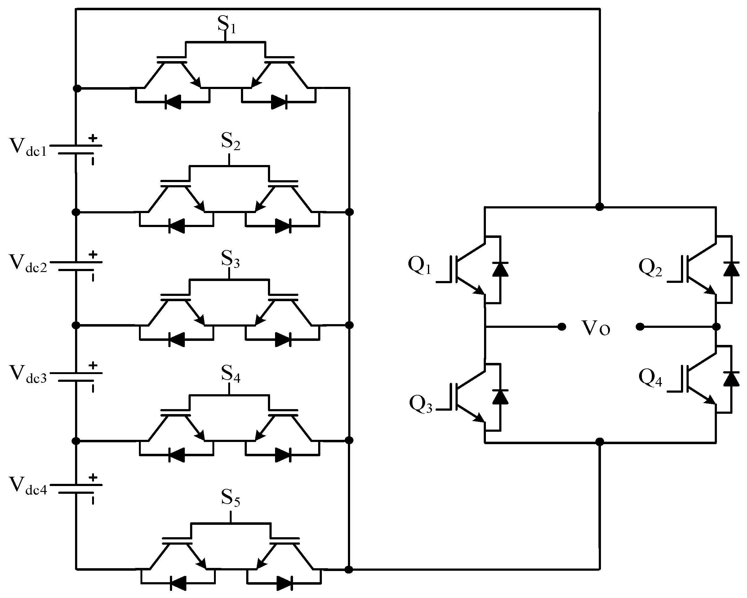
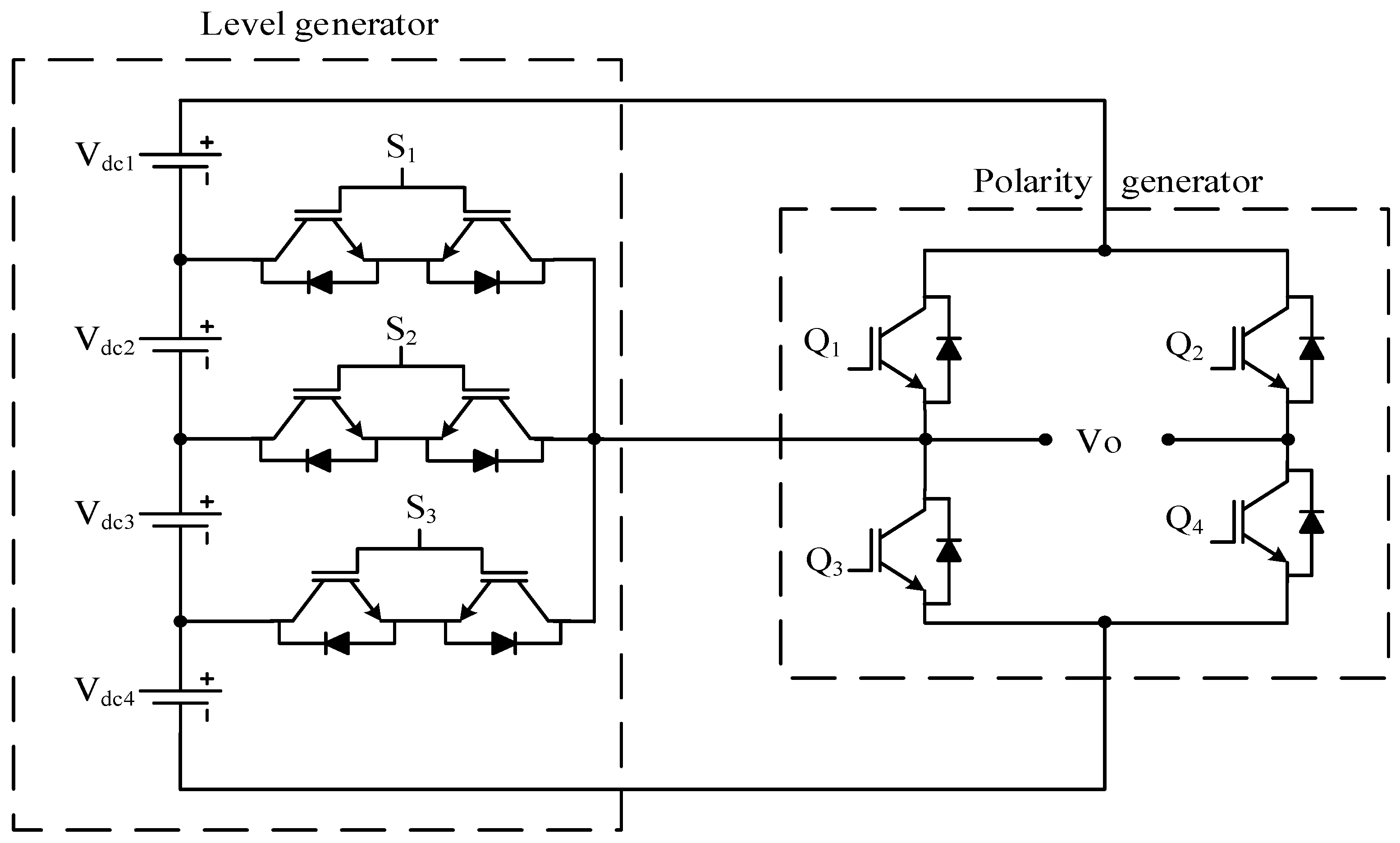
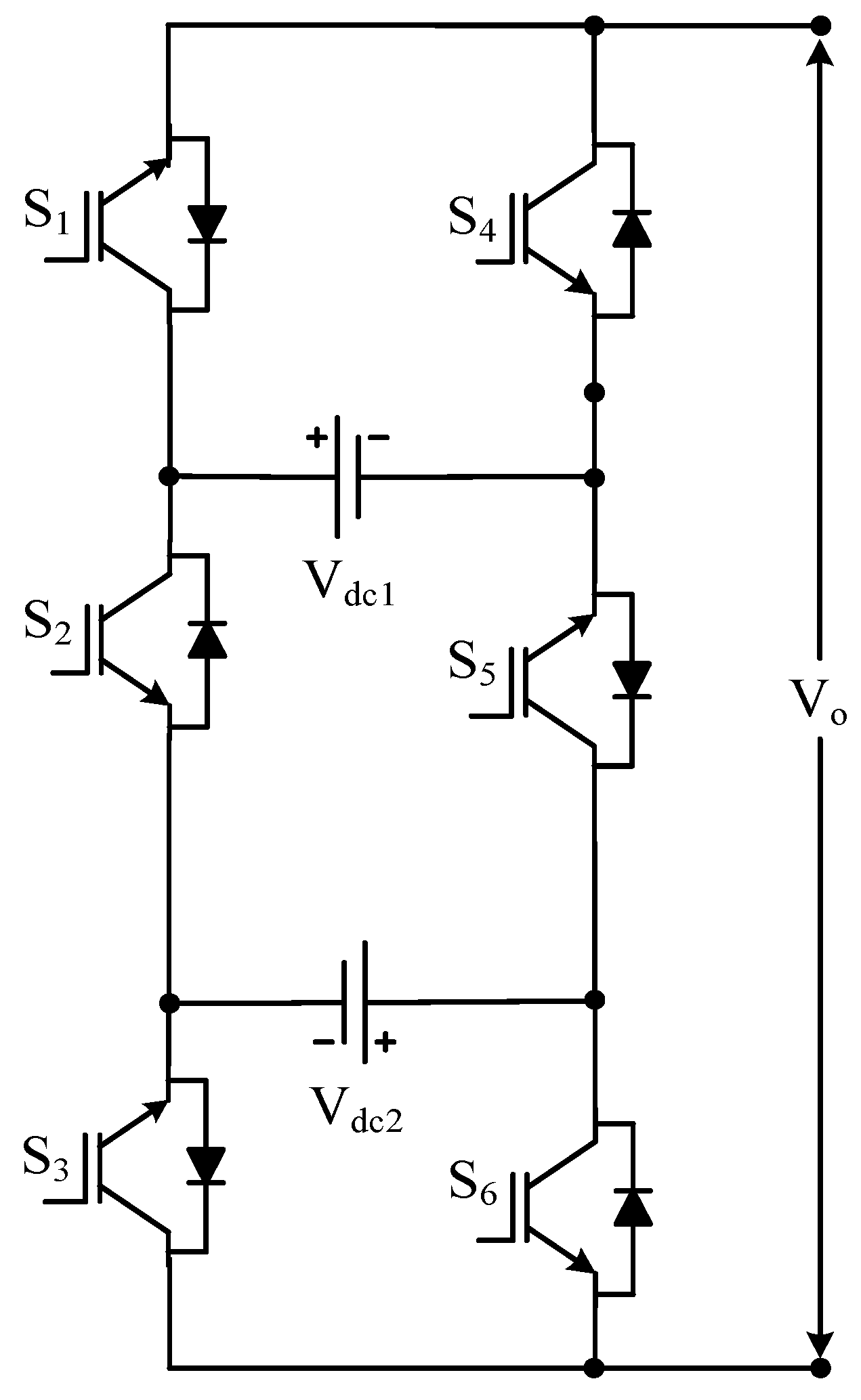
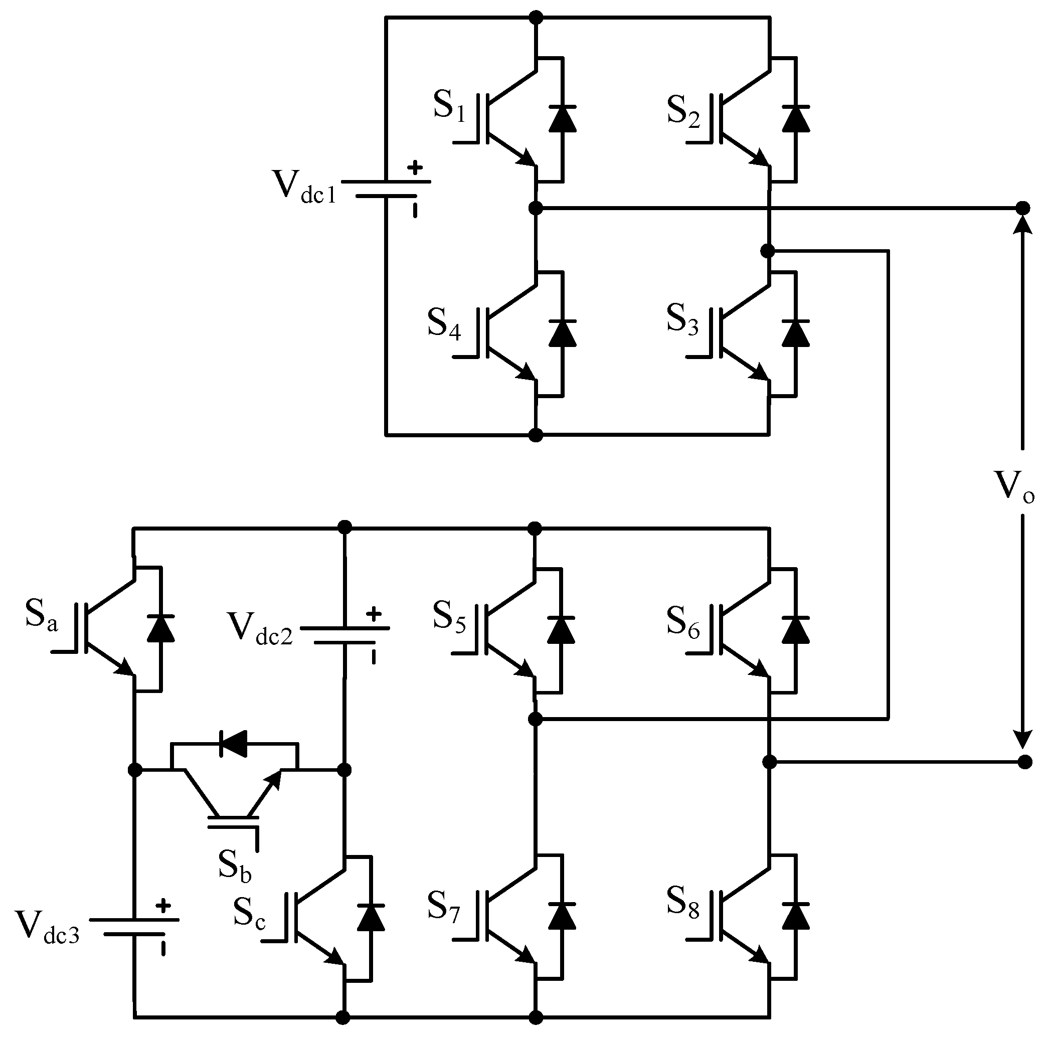
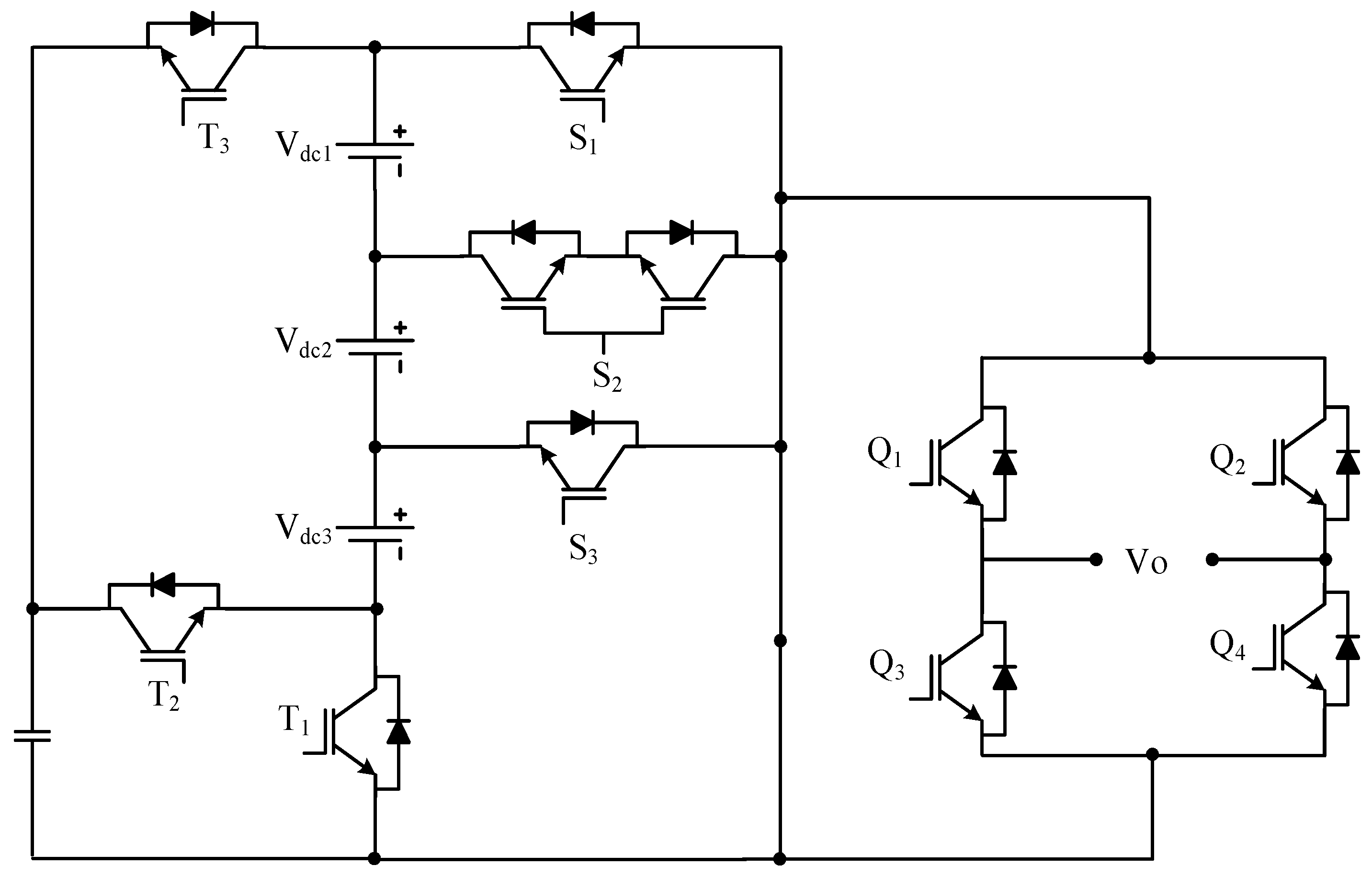
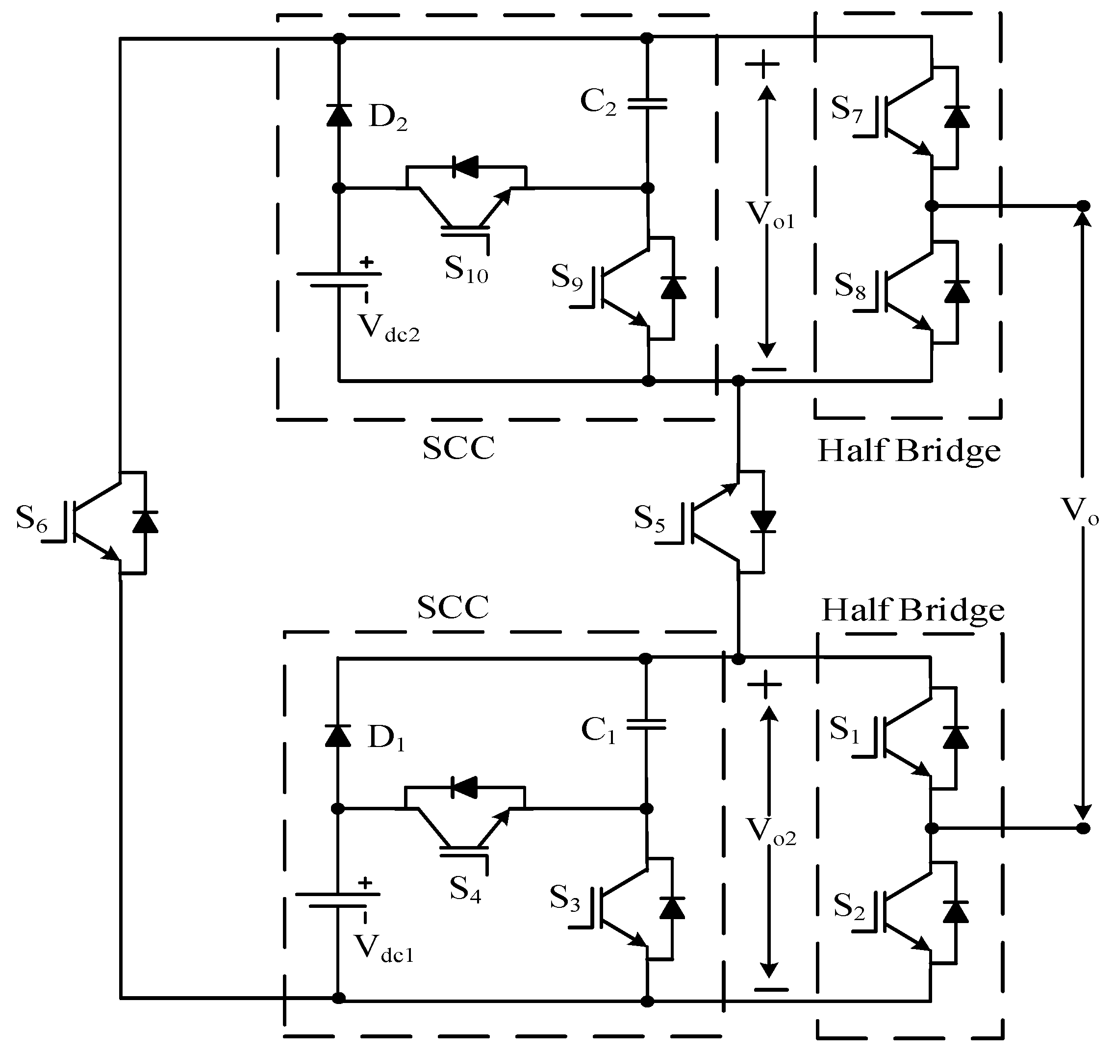
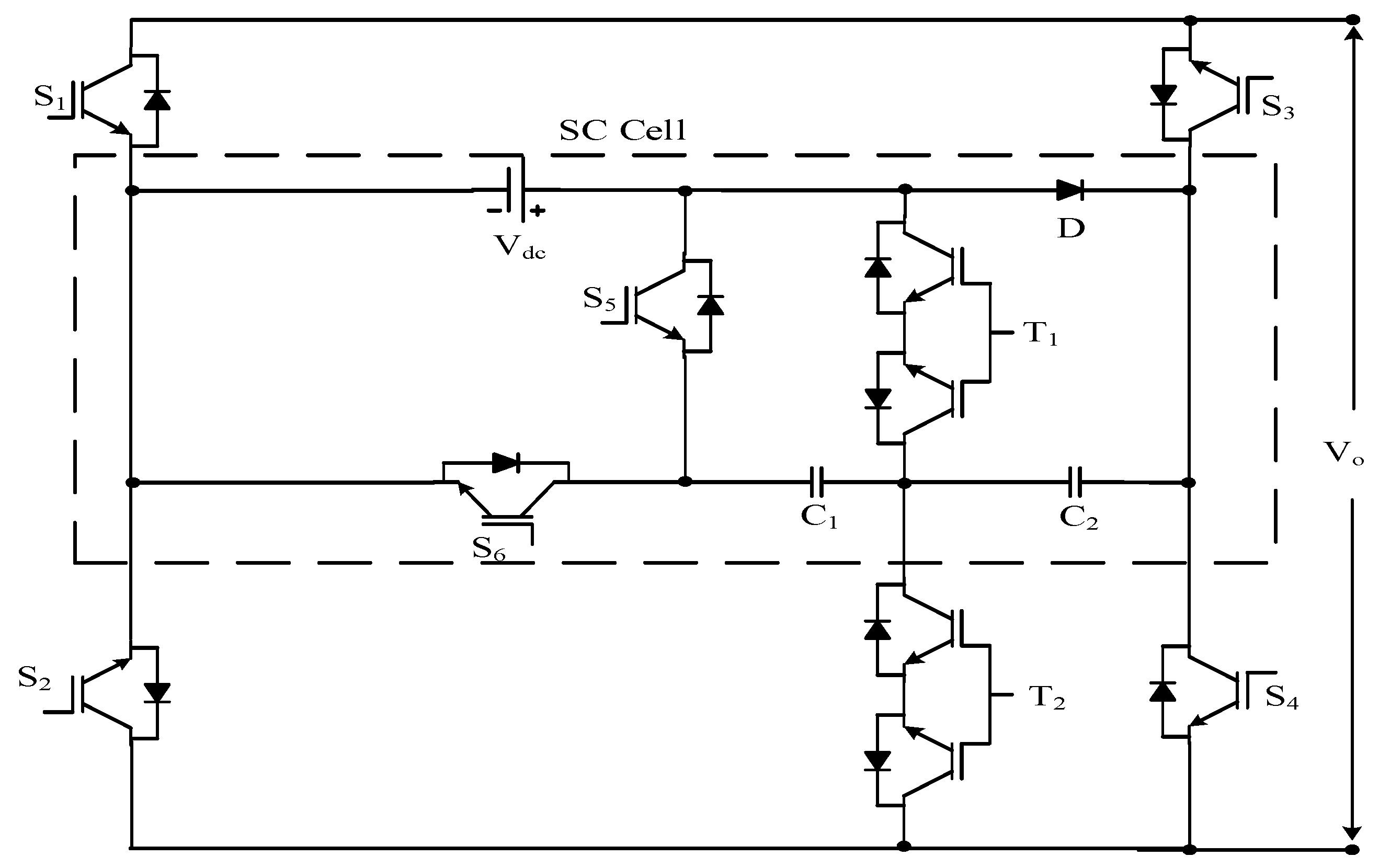
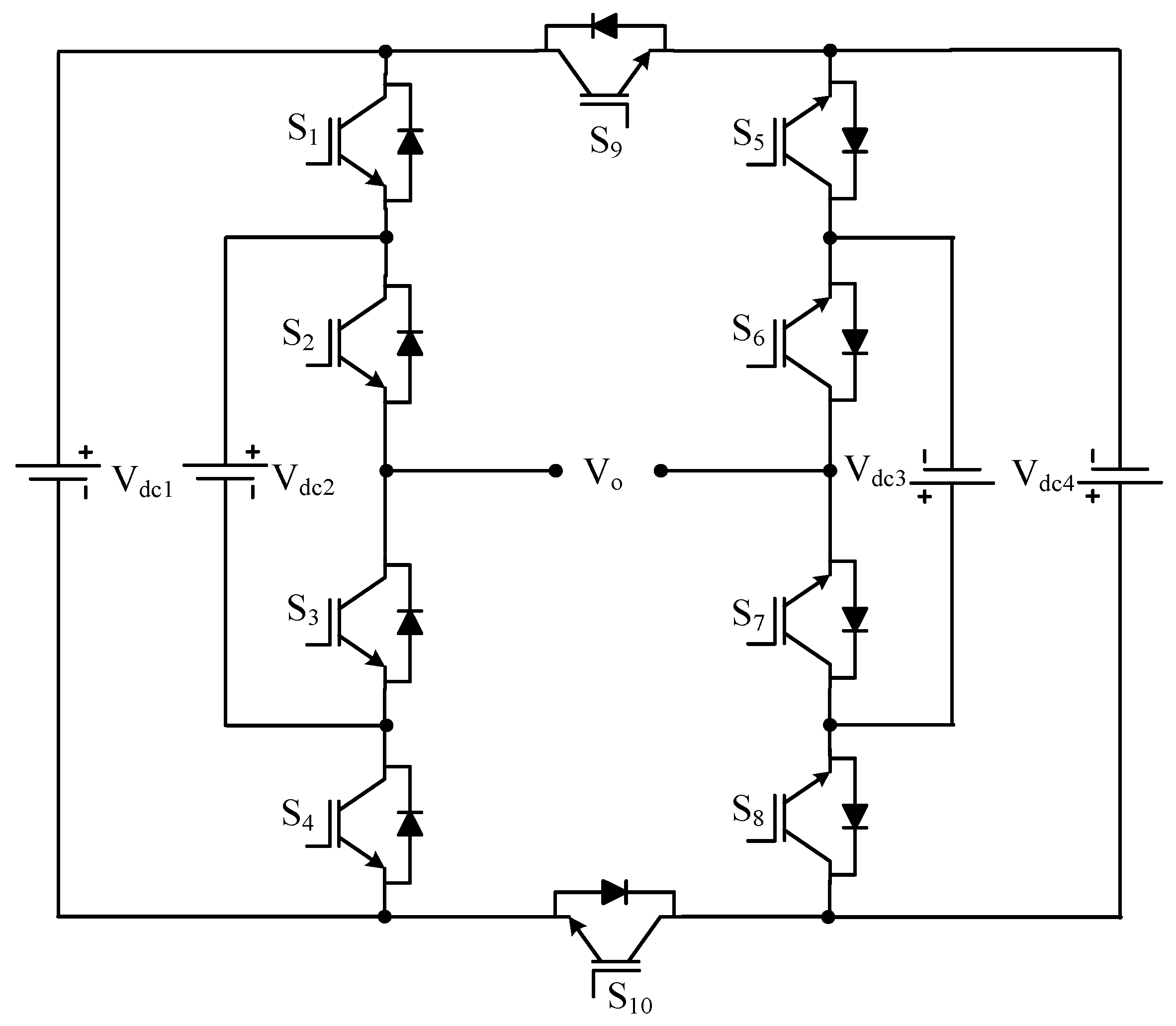
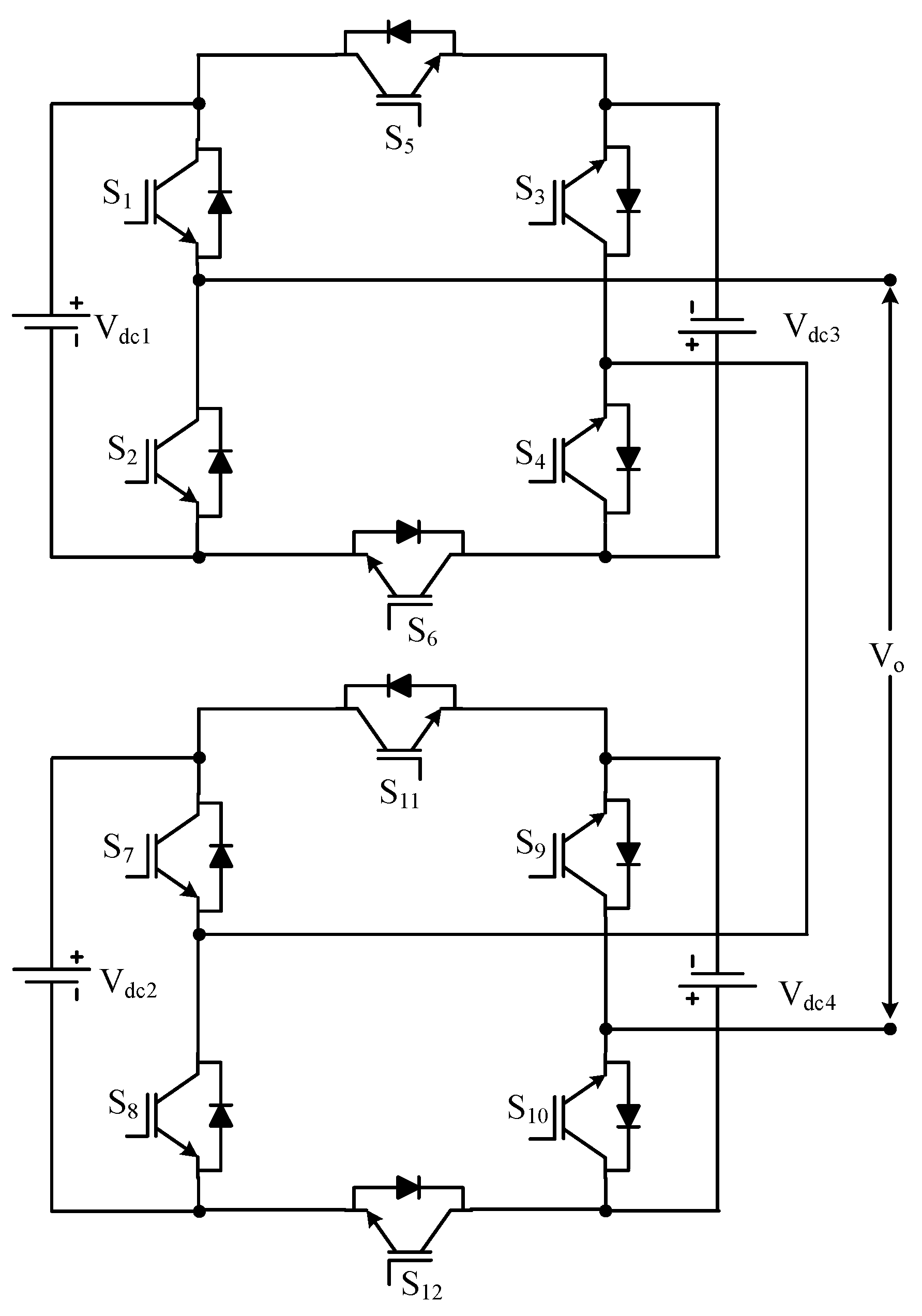
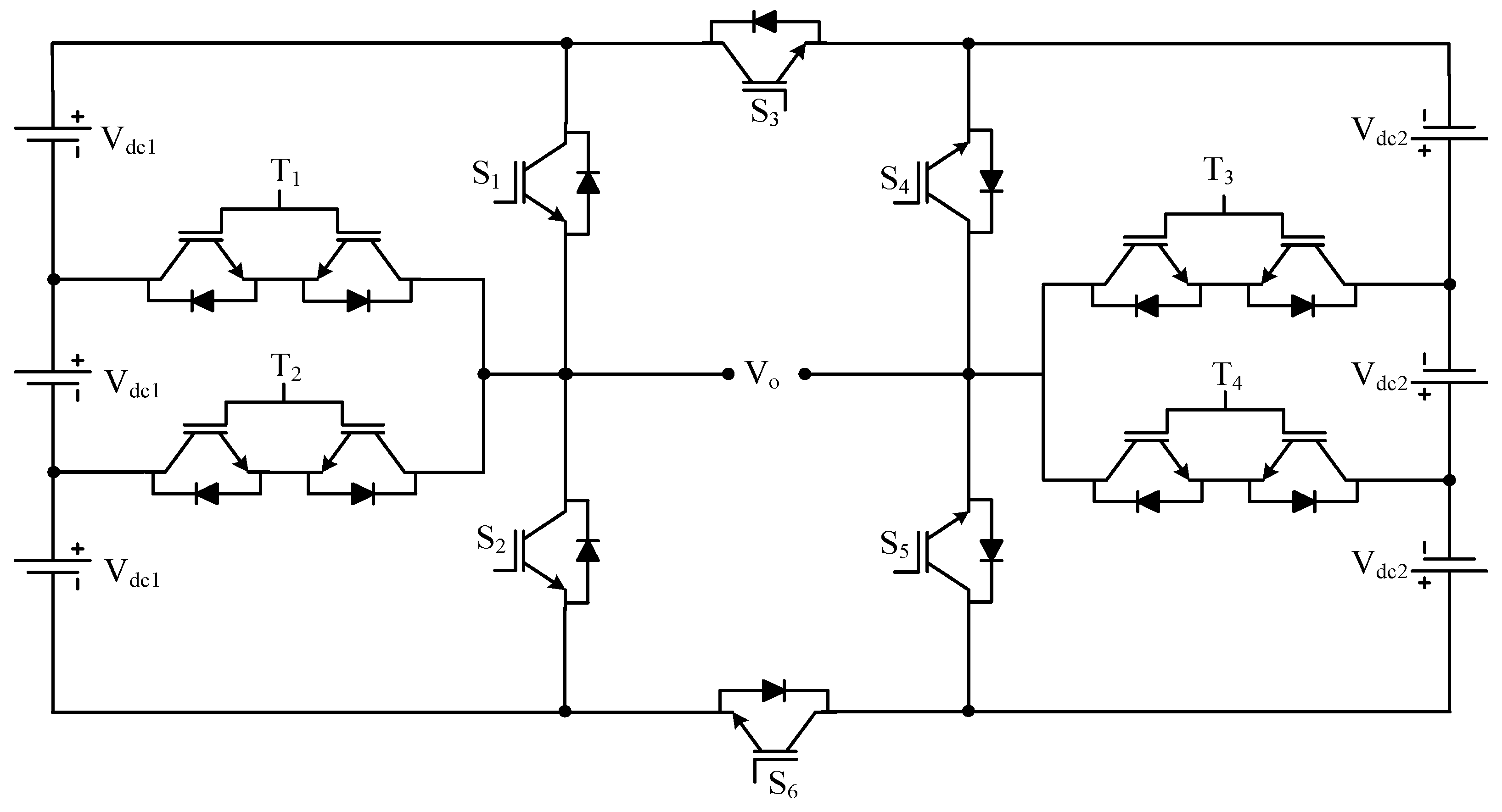
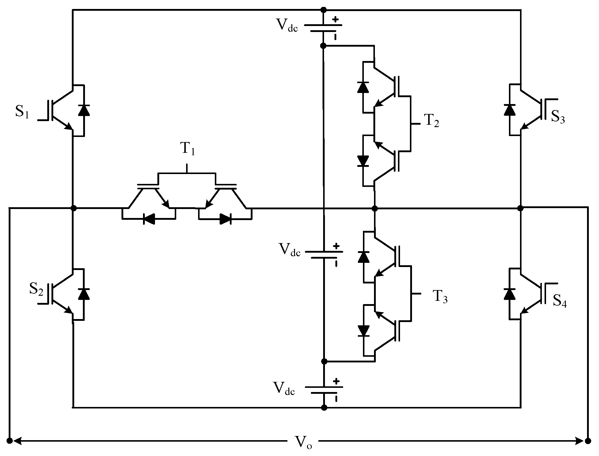

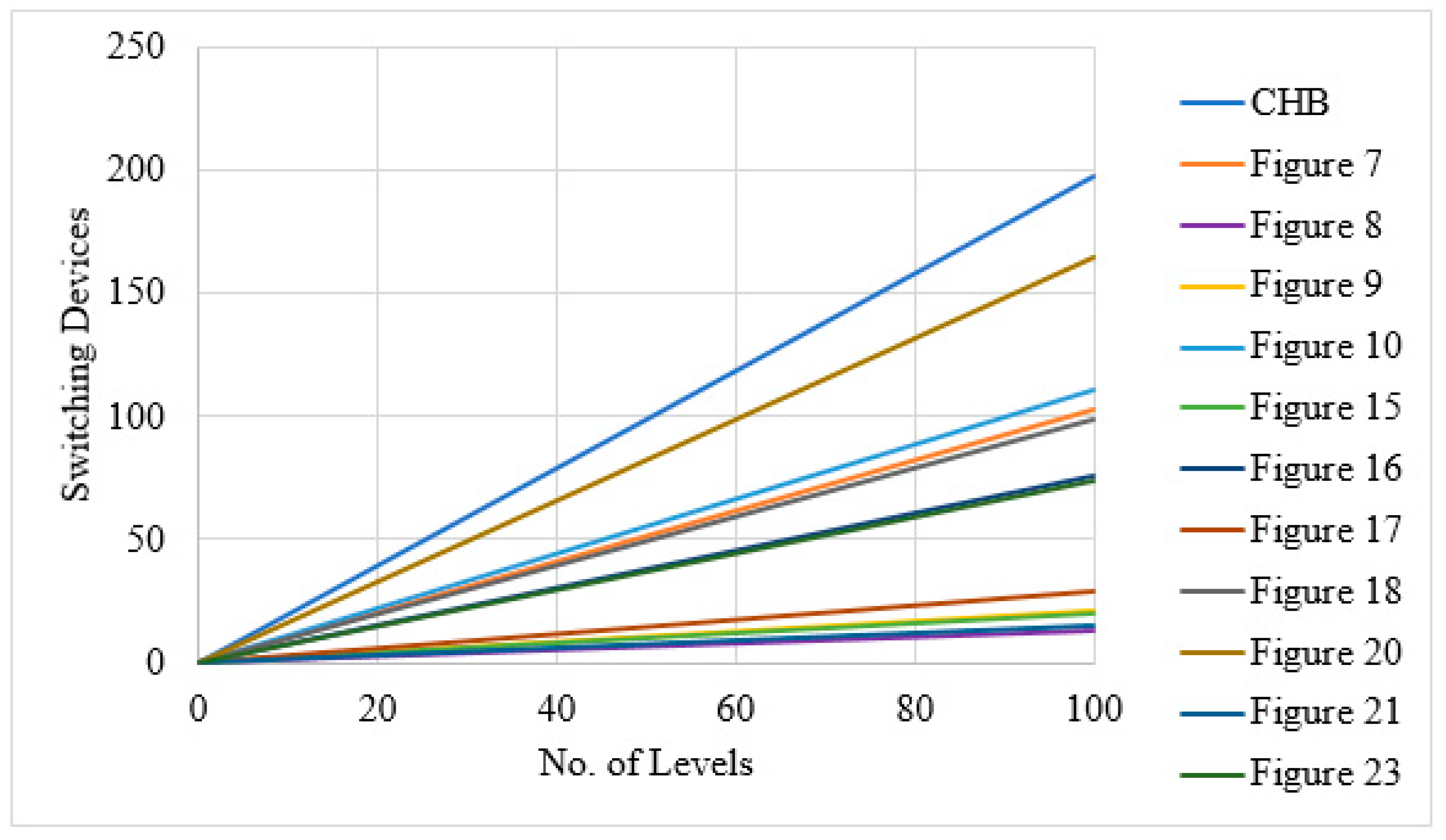
| Sr No. | Implementation Factors | NPC | FC | CHB |
|---|---|---|---|---|
| 1 | Switching devices | |||
| 2 | DC sources | |||
| 3 | Voltage levels | |||
| 4 | Clamping diodes | |||
| 5 | DC side capacitors | |||
| 6 | Freewheeling diodes | |||
| 7 | Balancing capacitor | |||
| 8 | Carrier waves | |||
| 9 | Modularity | Low | High | High |
| 10 | Design complexity | Low | Medium | High |
| 11 | Structure | Symmetric, bulky | Symmetric, bulky | Symmetric, light |
| 12 | Switch/source utilization | Poor | Good | Good |
| 13 | Implementation complexity | Low | Medium | High |
| 14 | Control concern | Voltage balancing | Voltage setup | Power sharing |
| 15 | Redundancy | Line | Phase and line | Phase |
| 16 | Fault tolerance | Difficult | Easy | Easy |
| 17 | Cost | Low | High | Medium |
| 18 | Introduced by | Nabae, Takashi, and Akagi | Meynard | Baker and Bannister |
| 19 | Introduced year | 1981 | 1992 | 1975 |
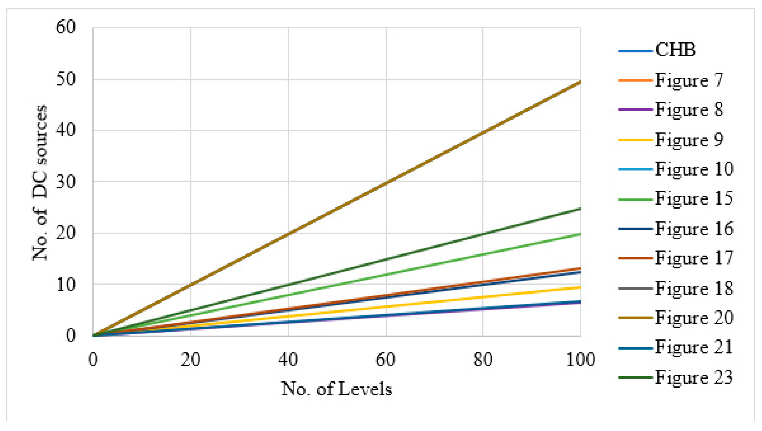
| Type RDC-MLI | of | Figure | Reference | ||
|---|---|---|---|---|---|
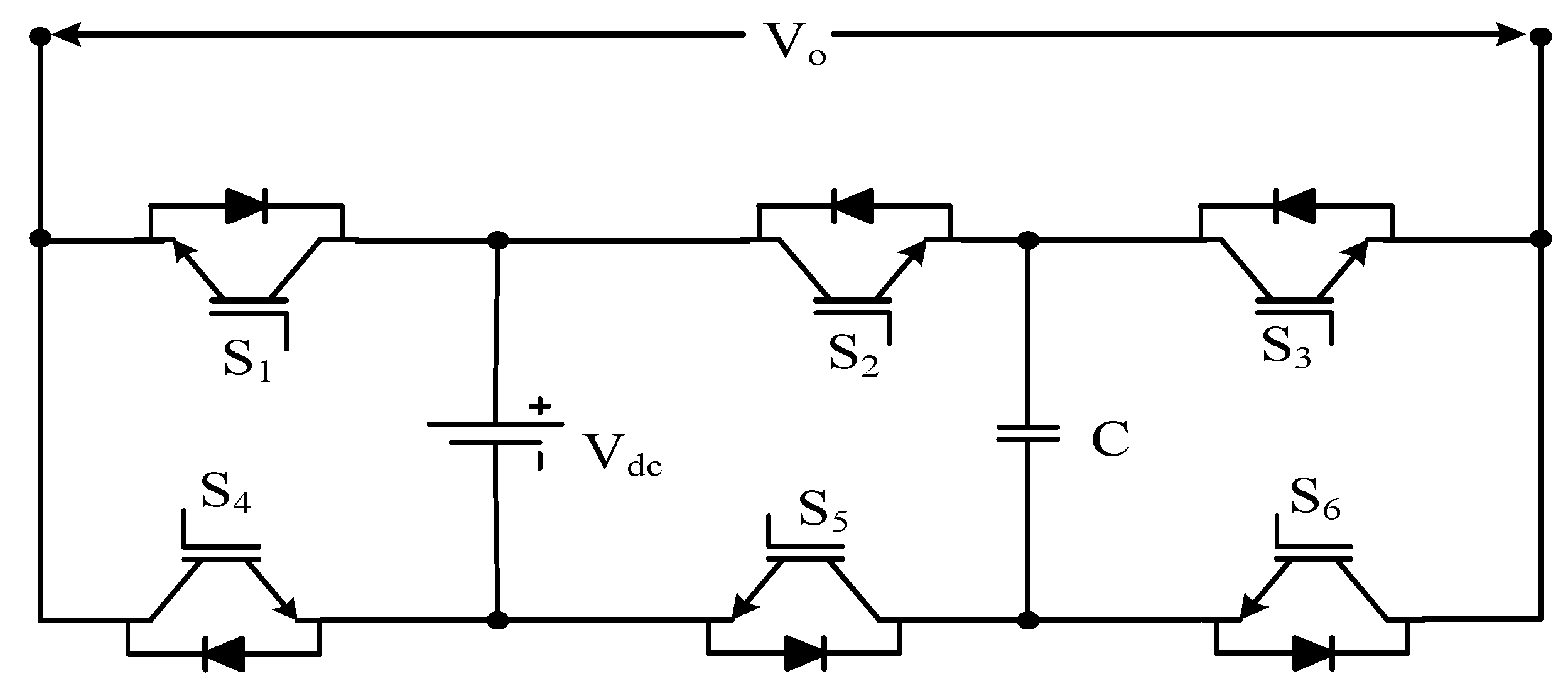
(symmetrical) (asymmetrical) 2 | (symmetrical) (asymmetrical) | Cascaded half-bridge MLI using sub cells | Figure 7 | [16] | |
Where is number of cells | Cascaded half- bridge MLI with reverse polarity cell | Figure 8 | [66] | ||
| BS-MLI | Figure 9 | [17] | |||
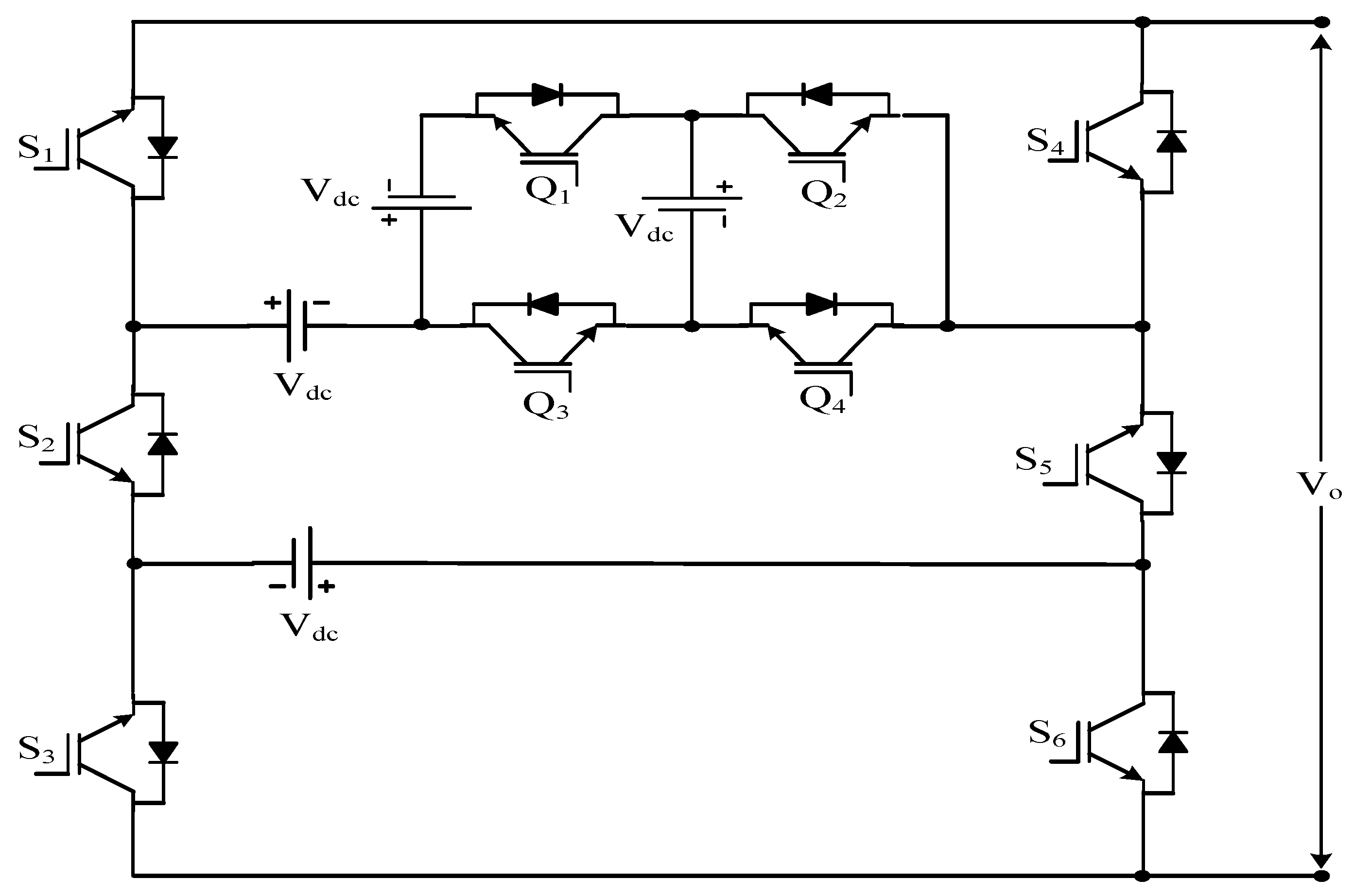
| MLM MLI | Figure 10 | [71] | |||
| SMLI | Figure 15 | [85] | |||
| BSCMLI | Figure 16 | [86] | |||
| Developed H-bridge MLI | Figure 17 | [97] | |||
| 8 ns Where ns is number of sub modules | Cascaded MLI with sub module | Figure 18 | [99] | ||
| 10 ncm Where ncm is number of cascaded modules | CCMMLI | Figure 20 | [101] | ||
Where nc is total number of capacitors and DC sources | PUCMLI | Figure 21 | [102] | ||
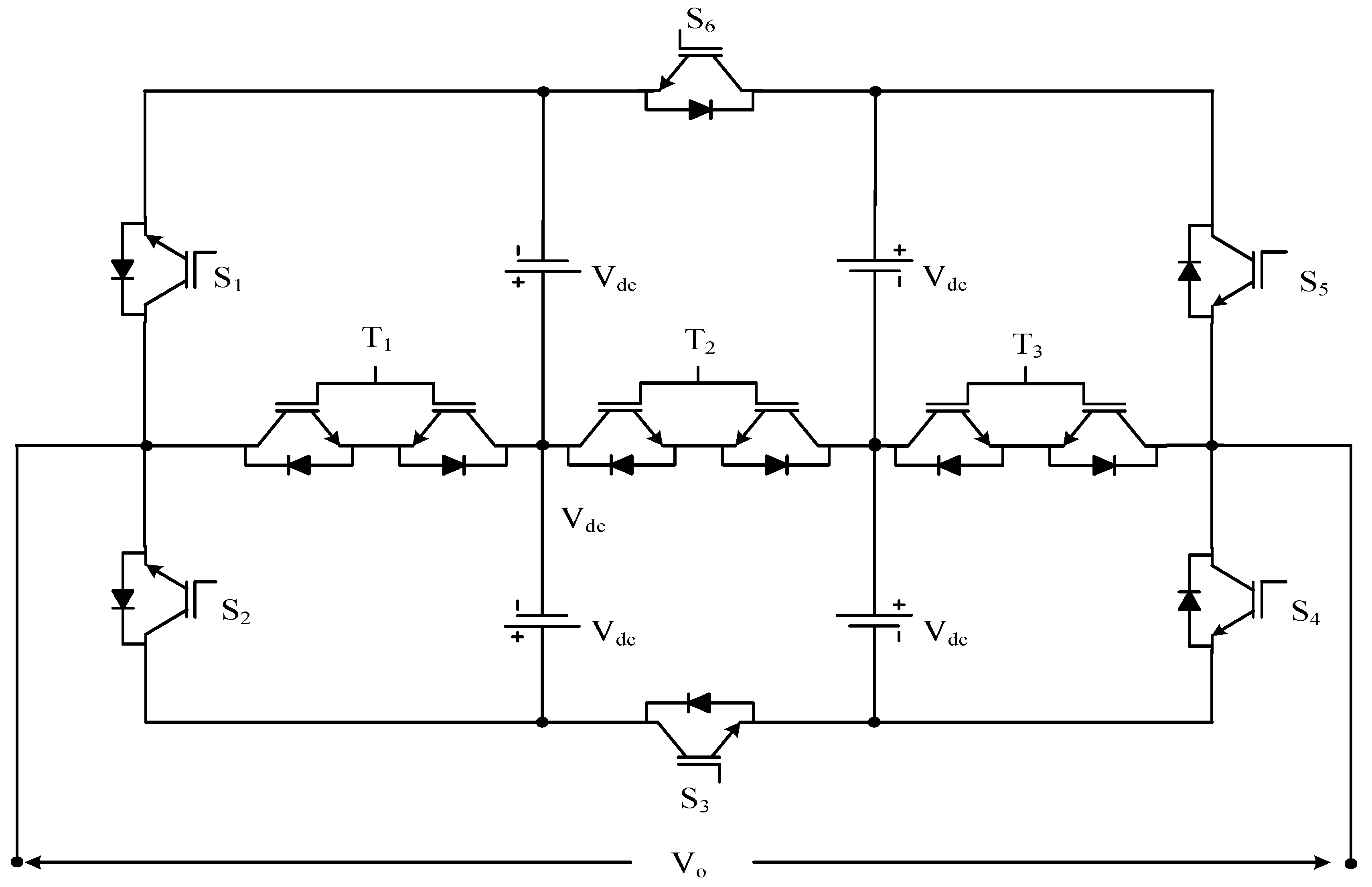
| 12 nst Where nst is number of ST modules | ST module type MLI | Figure 23 | [107] | ||
Where nh is number of half-bridge configured sources | Double H-bridge MLI | Figure 24 | [108] | ||
| Reference | Author (Year) | MLI Type | Modulation Scheme | Calculated Parameters | Software | Controller | Summary |
|---|---|---|---|---|---|---|---|
| [16] | Babaei, E et al. (2009) | Cascaded half-bridge MLI | Fundamental switching frequency technique | THD, output voltage | PSCAD | 89C52 ATMEL micro-controller | Reduced device count topology sub cells were presented, which were extended to form a cascaded connection. Three algorithms were also presented to find out the components and voltage levels. The method was validated with simulation and experimental results. |
| [17] | Babaei, E et al. (2007) | common emitter bi-directional switch based MLI | Switching angle | THD, Standing voltage | PSCAD/EMTDC | 89C52 ATMEL micro-controller | RSB-MLI was proposed for the series connection of sub multilevel inverters. Theoretical issues were verified with simulated and experimental results with new 49-level inverter. |
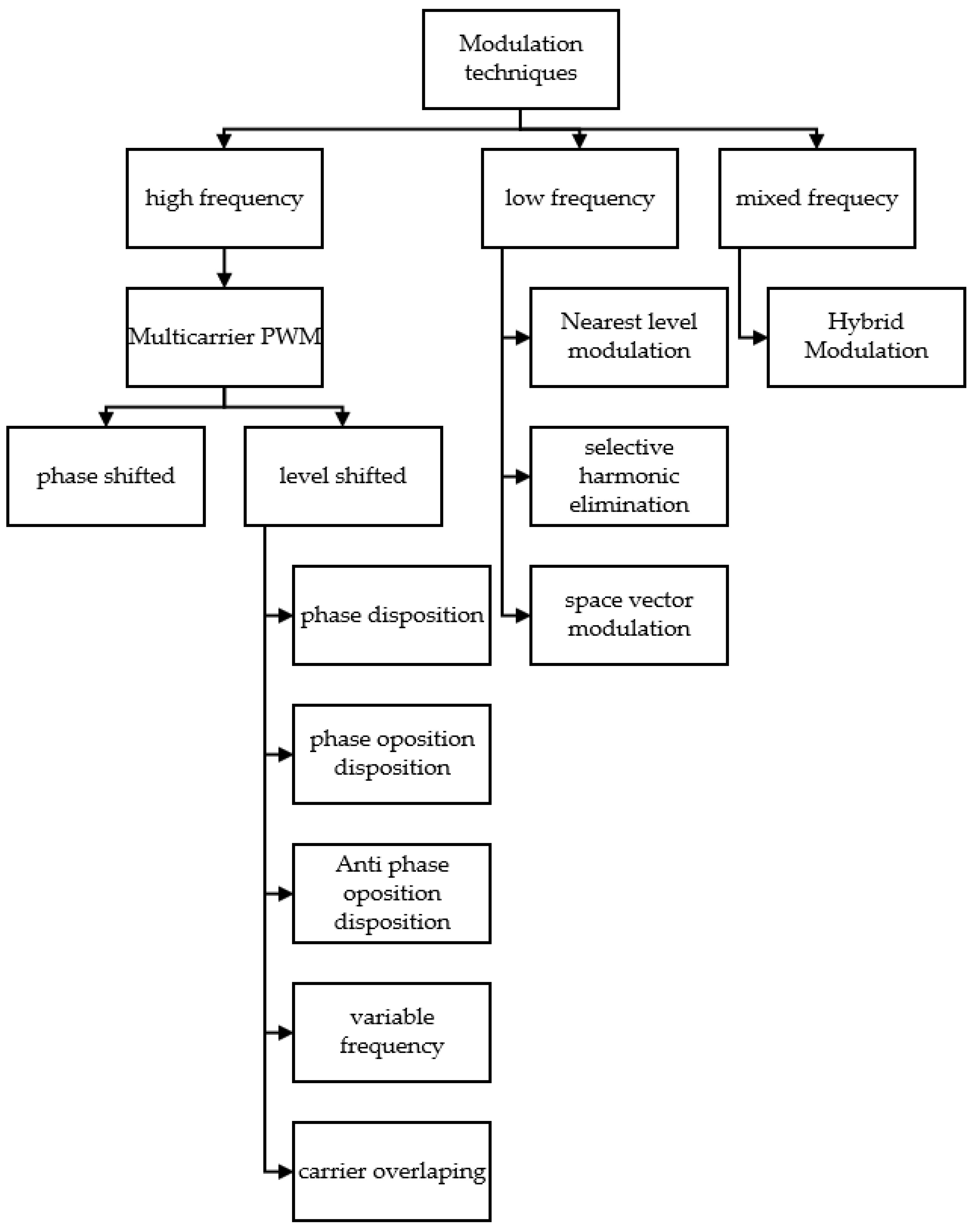
| [60] | Kotb, K.M et al. (2016) | cascaded half-bridge inverter | IPD (In phase deposition), POD (Phase opposite deposition), APOD (Alternative POD) | THD | MATLAB/ Simulink | NI PCI-6013 | Multicarrier PWM techniques were employed in a 15-level cascaded half-bridge inverter. |
| [66] | Ahmed, M et al. (2017) | asymmetric cascaded half-bridge inverter | selective harmonic elimination | THD | MATLAB/ Simulink | DSP TMS320F28335 controller | Authors introduced the topology with reverse polarity cell; therefore, it did not require polarity changer, thus reducing the switching devices, costs, and complexities of the circuit. |
| [71] | Gupta, K.K. and Jain, S (2014) | SCSS-MLI | PD-SPWM | THD, conduction losses, switching losses | MATLAB/ Simulink | DS1103 dSpace | A novel topology and its principle of operation was presented. The simulation results of this topology were also compared with conventional topologies. |
| [80] | Ebrahimi, J et al. (2012) | MLM-based MLI | - | THD, conduction losses, switching losses | PSCAD/EMTDC | ATMEL 89C52 micro-controller | The multilevel module based MLI was proposed in this study. Various optimal structures related with reduced device count were also presented. The proposed topology was evaluated with its prototype hardware and simulation. |
| [81] | Babaei, E (2010) | CHB-MLI using sub cells | switching angle | -- | PSCAD/EMTDC | 89C52 ATMEL micro-controller | The authors developed bi-directional based topologies in this study. Authors presented how the basic units can be extended, and also these extended units were configured in a cascaded connection. The performances of these topologies were validated with simulated and prototype results. |
| Reference | Year | MLI | Modulation Scheme | Calculated Parameters | Software | Controller | MPPT Algorithm | PV Configuration | |||
|---|---|---|---|---|---|---|---|---|---|---|---|
| Configuration | * | * | * | ||||||||
| [111] | 2019 | Modified CHB | 9 | 8 | 4 | PD, POD, APOD | THD, output voltage | MATLAB/ Simulink | PIC 16F877A Micro-controller | - | Standalone |
| [112] | 2019 | Reduced switch H- bridge-based (RSHB) MLI with LDC | 9 | 17 | 7 | SHE-PWM PD-PWM | THD, output voltage | MATLAB/ Simulink | Arduino Mega 2560 | Incremental conductance (IC) | Standalone |
| [113] | 2020 | Dual source multilevel inverter | 9 | 11 | 2 | NLM | THD, output voltage, voltage stress, switching and conduction losses, efficiency | MATLAB/ Simulink | FPGA Spartan 6 processor | - | Standalone |
| [114] | 2019 | Dual-mode interleaved multilevel inverter | 10 | 1 | PWM | THD, Power loss | STMicroelectronics STM32F407 DSP | - | Grid connected | ||
| [115] | 2021 | Improved H- bridge multilevel inverter | 6 | 5 | 2 | PWM | THD, Power loss, total standing voltage | MATLAB/ Simulink (R2009a) | dSPACE Micro Lab Box | IC | Grid connected |
| [116] | 2019 | Modified H-bridge MLI | 31 | 8 | 4 | PWM | THD | MATLAB/ Simulink | FPGA Spartan | Artificial neural network | Standalone |
| [117] | 2022 | Cascaded H- bridge sub-MLI | 15 | 7 | 3 | PD-CPWM | THD | MATLAB/ Simulink | Xilinx Spartan 3E-500 FPGA | Fuzzy logic | Standalone |
| [118] | 2016 | CHB with double level circuit | 13 | 14 | 4 | PD-CPWM | THD, Power loss | MATLAB/ Simulink | dSpace 1104 controller | Perturb and observe (P & O) | Standalone |
| [119] | 2020 | Voltage level boost (VLB) MLI | 15 | 10 | 5 | PD-CPWM | THD, Power loss | MATLAB/ Simulink | DSP controller | IC | Grid connected |
| [120] | 2020 | Micro multilevel inverter | 5 | 5 | 2 | PD-CPWM | THD, Power loss | MATLAB/ Simulink | d-SPACE 1104 | P & O | Standalone |
| [121] | 2020 | Switched capacitor MLI | 29 | 9 | 3 | SHE- PWM | THD, Power loss | MATLAB/ Simulink | DSPIC30F2010 controller | Grey Wolf optimization technique and fuzzy logic control | Standalone |
| [122] | 2023 | Switched capacitor MLI | 7 | 8 | 1 | Anti predatory particle swarm optimization | THD | MATLAB/ Simulink | - | Fuzzy controller | Standalone |
| [123] | 2023 | S-packed U-cells | 5 | 5 | 1 | PWM | THD | MATLAB/ Simulink | - | IC with hysteresis control | Grid connected |
Disclaimer/Publisher’s Note: The statements, opinions and data contained in all publications are solely those of the individual author(s) and contributor(s) and not of MDPI and/or the editor(s). MDPI and/or the editor(s) disclaim responsibility for any injury to people or property resulting from any ideas, methods, instructions or products referred to in the content. |
© 2023 by the authors. Licensee MDPI, Basel, Switzerland. This article is an open access article distributed under the terms and conditions of the Creative Commons Attribution (CC BY) license (https://creativecommons.org/licenses/by/4.0/).
Share and Cite
Memon, A.J.; Mahar, M.A.; Larik, A.S.; Shaikh, M.M. A Comprehensive Review of Reduced Device Count Multilevel Inverters for PV Systems. Energies 2023, 16, 5638. https://doi.org/10.3390/en16155638
Memon AJ, Mahar MA, Larik AS, Shaikh MM. A Comprehensive Review of Reduced Device Count Multilevel Inverters for PV Systems. Energies. 2023; 16(15):5638. https://doi.org/10.3390/en16155638
Chicago/Turabian StyleMemon, Abdul Jabbar, Mukhtiar Ahmed Mahar, Abdul Sattar Larik, and Muhammad Mujtaba Shaikh. 2023. "A Comprehensive Review of Reduced Device Count Multilevel Inverters for PV Systems" Energies 16, no. 15: 5638. https://doi.org/10.3390/en16155638
APA StyleMemon, A. J., Mahar, M. A., Larik, A. S., & Shaikh, M. M. (2023). A Comprehensive Review of Reduced Device Count Multilevel Inverters for PV Systems. Energies, 16(15), 5638. https://doi.org/10.3390/en16155638


