Article

Research on the Optimization of Energy–Carbon Co-Sharing Operation in Multiple Multi-Energy Microgrids Based on Nash Negotiation

College of Energy and Electrical Engineering, Hohai University, Nanjing 211100, China
*
Author to whom correspondence should be addressed.
Energies 2023, 16(15), 5655; https://doi.org/10.3390/en16155655
Submission received: 4 July 2023 / Revised: 23 July 2023 / Accepted: 24 July 2023 / Published: 27 July 2023
(This article belongs to the Topic Low-Carbon Power and Energy Systems)

Abstract

:
Efficient and low-carbon energy utilization is a crucial aspect of promoting green and sustainable development. Multi-energy microgrids, which incorporate multiple interchangeable energy types, offer effective solutions for low-carbon and efficient energy consumption. This study aims to investigate the sharing of energy and carbon in multiple multi-energy microgrids (MMEMs) to enhance their economic impact, low-carbon attributes, and the efficient utilization of renewable energy. In this paper, an energy–carbon co-sharing operation model is established, incorporating carbon capture systems (CCSs) and two-stage power-to-gas (P2G) devices within the MMEMs to actualize low-carbon operation. Furthermore, based on cooperative game theory, this paper establishes an energy–carbon co-sharing Nash negotiation model and negotiates based on the energy–carbon contribution of each subject in the cooperation as bargaining power so as to maximize both the benefits of the MMEM alliance and the distribution of the cooperation benefits. The case study results show that the overall benefits of the alliance can be increased through Nash negotiation. Energy–carbon co-sharing can effectively increase the renewable energy consumption rate of 8.34%, 8.78%, and 8.83% for each multi-energy microgrid, and the overall carbon emission reduction rate reaches 17.81%. Meanwhile, the distribution of the benefits according to the energy–carbon co-sharing contribution capacity of each entity is fairer.

1. Introduction

In the context of energy transition, the development of cleaner, low-carbon energy systems lies at the heart of the contemporary energy revolution. The comprehensive utilization of energy provides an efficient solution for energy innovation and low-carbon development [1,2]. Similar to integrated energy systems, multi-energy microgrids, which serve as an extension of traditional microgrids, are predicted to become the terminal energy supply systems for the Energy Internet and a key developmental trend in future energy systems [3]. At present, research concerning the optimal operation of multi-energy microgrids has made some progress. Ju et al. [4] considered the uncertainty of wind and solar power generation and established a two-layer optimization model based on price and incentive demand response. To enhance the operational flexibility of microgrid energy hubs, Ma et al. [5] proposed a general modeling method for microgrid energy flow, took the minimum daily operating cost as the objective function, and established a mixed-integer linear optimization problem considering demand response. Zhang et al. [6] aimed at the operating characteristics of an island-type microgrid, introduced cooling, heating, and electric load demand response, and proposed an optimal scheduling model considering multiple types of demand responses, and the results showed that considering various demand responses can bolster the flexibility and cost-effectiveness of island microgrids. The above research focused on the multi-energy complementarity of a single microgrid and its demand response with users, and some scholars have studied energy sharing among multiple subjects. Chiş and Koivunen [7] utilized an alliance game optimization method and distributed joint income among alliance members according to the Shapley value. To improve the economic performance of microgrid users, Liu et al. [8] proposed an energy contribution model based on price-driven demand response and designed an equivalent cost model from two aspects of economic cost and user willingness.
In terms of solution methods, the existing research on the optimal operation of micro-energy networks has mostly adopted the particle swarm algorithm [9], game theory [10,11], and other approaches, and it has focused on the economic optimization operation strategy considering energy management. Maharjan et al. [12] established a Stackelberg game model for multiple suppliers and a large number of users in smart grid. Wei et al. [13] proposed a novel multi-master and multi-slave layered Stackelberg game for the analysis of multi-energy transactions. Lin et al. [14] introduced an energy trading model and a solution algorithm based on the two-tier Stackelberg game for “power supply company-microgrid-user” scenarios, which considered multi-type energy transactions among multiple stakeholders in the game process and resolved conflicts between different parties. The above are studies of non-cooperative games in the optimization of microgrid energy management, where each subject in a non-cooperative game is regarded as opposite, so there is a lack of consideration for the overall interests, and the Nash equilibrium is usually locally optimal. With this in mind, Kim et al. [15] adopted the Nash negotiation method to establish a multi-microgrid power trading cooperation model and realized the distribution of multi-microgrid cooperation benefits through the resolution of the Nash product. Xu et al. [16] proposed a two-layer optimal scheduling strategy for a multi-microgrid system that considered both the demand response of energy-consuming users and the shared energy storage, introduced cooperative games in the upper layer to solve the upper optimization model, and converted the lower model into KKT optimal conditions. Wu et al. [17] further considered the optimal operation mechanism of carbon emission quota and carbon trading and established a multi-microgrid power sharing cooperative operation model based on the Nash negotiation theory.
Summarizing the literature above, the existing studies on the energy sharing of MMEMs have mostly focused on single energy sharing and have neglected carbon sharing. To further mitigate the carbon emissions of the system, this study considers carbon sharing between MMEMs in conjunction with energy sharing. To take into account the interests of individuals and alliances, the Nash negotiation method is used to construct an energy–carbon co-sharing cooperative game model. In accordance with the two fundamental principles of cooperative games, the cooperative game model is decomposed into two sub-models of the maximum alliance benefit and the income distribution, and the bargaining power of different subjects is evaluated according to the energy sharing contribution and carbon sharing contribution. To reduce the risk of privacy leakage and balance the privacy protection of different entities, both sub-models are solved by using the ADMM algorithm.
The structure of this study is as follows: Section 2 presents the structure of MMEMs, including the P2G, CHP, GB, and CCS operating models and the energy storage system model; Section 3 introduces the cost model of MMEMs; Section 4 introduces the Nash negotiation method based on cooperative games; Section 5 conducts a case study; and conclusions are drawn in Section 6.

2. Energy–Carbon Co-Sharing Operation Model of Multiple Multi-Energy Microgrids

2.1. Subsection

The MMEM operation architecture designed in this paper is shown in Figure 1.
Energy is adjusted and optimized by energy conversion equipment in each multi-energy microgrid (MEM) to accommodate the energy demands. In the energy–carbon sharing architecture considered in this paper, if the renewable energy output of the multi-energy microgrid is surplus, it first supplies energy to other multi-energy microgrids. When its own power demand is insufficient, it purchases electricity from other multi-energy microgrids to meet its own electric energy needs and finally consider purchasing power from the grid.
Since the cogeneration of heating and power (CHP) and gas boilers (GB) emit a large amount of carbon dioxide, the carbon dioxide generated during the power generation cycle enters the MEM with CCS, and the captured carbon dioxide is directed into the P2G module.

2.2. Operation Model of Multiple Multi-Energy Microgrids

2.2.1. Operation Model of P2G

The P2G model in this paper includes two stages. First, an electrolyzer (EL) separates water into hydrogen and oxygen, and a methane reactor (MR) then reacts a portion of the hydrogen with carbon dioxide to generate natural gas and water, while the remaining hydrogen is utilized as fuel to produce electricity and heat energy through a hydrogen fuel cell (HFC). The P2G conversion operation model is described as follows [18]:
  • Electrolyzer:
{ P i e l , H 2 ( t ) = η e , e l P i e , e l ( t ) P i , min e , e l P i e , e l ( t ) P i , max e , e l Δ P i , min e , e l P i e , e l ( t + 1 ) P i e , e l ( t ) Δ P i , max e , e l
where P i e l , H 2 ( t ) is the hydrogen energy output by the EL of MEM-i at time t, P i e , e l ( t ) is the hydrogen energy input to the EL of MEM-i at time t, η e , e l is the energy conversion efficiency of the EL, P i , max e , e l and P i , min e , e l are the upper and lower limits of the electrical energy input to the EL of MEM-i, respectively, and Δ P i , max e , e l and Δ P i , min e , e l are the ramping rate constraints.
  • Methane reactor:
    { P i m r , g ( t ) = η m r P i H 2 , m r ( t ) P i , min H 2 , m r P i H 2 , m r ( t ) P i , max H 2 , m r Δ P i , min H 2 , m r P i H 2 , m r ( t + 1 ) P i H 2 , m r ( t ) Δ P i , max H 2 , m r
    where P i m r , g ( t ) is the natural gas power output by the MR of MEM-i at time t, P i H 2 , m r ( t ) is the hydrogen energy input to the MR of MEM-i at time t, η m r is the energy conversion efficiency of the MR, P i , max H 2 , m r and P i , min H 2 , m r are the upper and lower limits of the hydrogen energy input to the MR of MEM-i, respectively, and Δ P i , max H 2 , m r and Δ P i , min H 2 , m r are the ramping rate constraints.
  • Hydrogen fuel cells:
    { P i h f c , e ( t ) = η e , h f c P i H 2 , h f c ( t ) P i h f c , h ( t ) = η h , h f c P i H 2 , h f c ( t ) P i , min H 2 , h f c P i H 2 , h f c ( t ) P i , max H 2 , h f c Δ P i , min H 2 , h f c P i H 2 , h f c ( t + 1 ) P i H 2 , h f c ( t ) Δ P i , max H 2 , h f c
    where P i h f c , e ( t ) is the electrical energy output by the HFC of MEM-i at time t, P i h f c , h ( t ) is the thermal energy output by the HFC of MEM-i at time t, η e , h f c is the electrical conversion efficiency of the HFC, η h , h f c is the thermal conversion efficiency of the HFC, P i H 2 , h f c ( t ) is the hydrogen energy input to the HFC of MEM-i at time t, P i , max H 2 , h f c and P i , min H 2 , h f c are the upper and lower limits of the hydrogen energy input to the HFC of MEM-i, respectively, and Δ P i , max H 2 , h f c and Δ P i , min H 2 , h f c are the ramping rate constraints.

2.2.2. Operation Model of the CHP

CHP powers the system by burning natural gas, simultaneously utilizing the generated waste heat to meet the heat load demand. The CHP operation model is as follows [18]:
{ P i c h p , e ( t ) = η e , c h p P i g , c h p ( t ) P i c h p , h ( t ) = η h , c h p P i g , c h p ( t ) P i , min g , c h p P i g , c h p ( t ) P i , max g , c h p Δ P i , min g , c h p P i g , c h p ( t + 1 ) P i g , c h p ( t ) Δ P i , max g , c h p
where is the electrical energy output by the CHP of MEM-i at time t, P i c h p , h ( t ) is the thermal energy output by the CHP of MEM-i at time t, P i g , c h p ( t ) is the natural gas power input to the CHP of MEM-i at time t, η e , c h p is the electrical conversion efficiency of the CHP, η h , c h p is the thermal conversion efficiency of the CHP, P i , max g , c h p and P i , min g , c h p are the upper and lower limits of the natural gas power input to the CHP of MEM-i, respectively, and Δ P i , max g , c h p and Δ P i , min g , c h p are the ramping rate constraints.

2.2.3. Operation Model of the GB

The operation model of the GB is as follows [18]:
{ P i g b , h ( t ) = η g b P i g , g b ( t ) P i , min g , g b P i g , g b ( t ) P i , max g , g b Δ P i , min g , g b P i g , g b ( t + 1 ) P i g , g b ( t ) Δ P i , max g , g b
where P i g b , h ( t ) is the thermal energy output by the GB of MEM-i at time t, P i g , g b ( t ) is the natural gas power input to the GB of MEM-i at time t, η g b is the conversion efficiency of the GB, P i , max g , g b and P i , min g , g b are the upper and lower limits of the natural gas power input to the GB of MEM-i, respectively, and Δ P i , max g , g b and Δ P i , min g , g b are the ramping rate constraints.

2.2.4. Operation Model of the CCS

The flue gas containing carbon dioxide from the power generation process enters the carbon capture device, and the carbon capture agent (e.g., sodium chloride) reacts with the carbon dioxide in the flue gas so that the carbon dioxide is adsorbed onto the carbon capture agent and then absorbed through purification treatment. The attached carbon dioxide is then used in the MR of the P2G system to synthesize natural gas for the system. The power demand of the CCS in this paper is supplied by CHP, and the CCS absorbs the carbon dioxide generated during the operation of the CHP and GB. The operating model of the CCS is as follows, and its operating power consumption is related to the amount of carbon dioxide captured [19]:
P i c c s ( t ) = γ c c s M i c c s ( t )
{ M i c c s ( t ) = σ c [ M i t r e ( t ) + M i j c f s ( t ) ] 0 M i t r e ( t ) M i c ( t )
M i c ( t ) = μ i c [ P i c h p , e ( t ) + P i c h p , h ( t ) + P i g b , h ( t ) ]
where P i c c s ( t ) is the power consumption of the CCS of MEM-i at time t, γ c c s is the conversion coefficient of the electrical energy consumed to capture carbon dioxide, M i c c s ( t ) is the amount of carbon dioxide captured by the CCS of MEM-i at time t, M i t r e ( t ) is the amount of carbon dioxide processed by the CCS, where the value does not exceed the total amount of carbon dioxide in the flue gas M i c ( t ) , M i c ( t ) is the total amount of carbon dioxide in the flue gas of MEM-i at time t, M i j c f s ( t ) is the amount of carbon dioxide shared between MEM-i and MEM-j at time t, σ c is the carbon dioxide capture rate of the CCS, which is taken as 90%, and μ i c is the carbon emission intensity of MEM-i.

2.2.5. Model of Electricity and Heat Load

The electricity load in each MEM includes a fixed electricity load, a cuttable electricity load, and transferable electricity load, and the heat load includes a fixed heat load and a cuttable heat load.
{ P i e , l o a d ( t ) = P i e , f ( t ) + P i e , t r a n s ( t ) + P i e , c u t ( t ) | t = 1 T P i e , t r a n s ( t ) Δ t | k e , t r a n s P i e , l o a d ( t ) 0 P i e , c u t ( t ) P i , max e , c u t
where P i e , l o a d ( t ) is the electricity load of MEM-i at time t, P i e , t r a n s ( t ) is the transferable electricity load of MEM-i at time t, P i e , c u t ( t ) is the cuttable electricity load of MEM-i at time t, k e , t r a n s is the transferable proportion of the electricity load, and P i , max e , c u t is the upper limit of the transferable electricity load of MEM-i.
{ P i h , l o a d ( t ) = P i h , f ( t ) + P i h , c u t ( t ) 0 P i h , c u t ( t ) P i , max h , c u t
where P i h , l o a d ( t ) is the heat load of MEM-i at time t, P i h , c u t ( t ) is the cuttable heat load of MEM-i at time t, and P i , max h , c u t is the upper limit of the cuttable heat load of MEM-i.

2.2.6. Operation Model of Energy Storage Devices

Energy storage devices play the role of enhancing stability, and their model is as follows [20]:
{ E i ( t ) = ( 1 u ) E ( t 1 ) + [ η c h a P i c h a ( t ) P i r e l ( t ) η r e l   ] Δ t E min E i ( t ) E max E i ( 0 ) = E i ( 24 )
where E max and E min are the maximum and minimum energy storage states, respectively, E i ( t ) is the energy storage status of the energy storage device of MEM-i at time t, u is the energy discharge ratio of the energy storage station, which can generally be ignored, η c h a and η r e l are the charge and discharge efficiency, respectively, and P i c h a ( t ) and P i r e l ( t ) are the charge and discharge power of the energy storage device of MEM-i at time t, respectively.
The energy storage device meets the following constraints:
{ 0 P i c h a ( t ) B t c h a P max c h a 0 P i r e l ( t ) B t r e l P max r e l B t c h a + B t r e l 1 B t c h a { 0 , 1 } , B t r e l { 0 , 1 }
where P max c h a is the maximum value of the energy storage charge power, P max r e l is the maximum value of the energy storage discharge power, and B t c h a and B t r e l are the charge and discharge states of the energy storage device, respectively, and are binary variables.

3. Cost Model of Multiple Multi-Energy Microgrids

3.1. Objective Function

The operation goal of MMEMs is to minimize operating costs, and its objective function is as follows:
min C i m e g = C i e , b u y C i e , s e l l + C i g , b u y + C i d r + C i e s + C i c f s + C i c o 2
where C i m e g is the operating costs of MEM-i, C i e , b u y is the cost of purchasing electricity of MEM-i, C i e , s e l l is the energy sales income of MEM-i, C i g , b u y is the cost of purchasing gas of MEM-i, C i c o 2 is the carbon trading cost of MEM-i, C i d r is the cost of the demand response of MEM-i, and C i c f s is the cost of carbon sharing of MEM-i.

3.1.1. Cost of Buying and Selling Energy

The energy purchase and sale costs of MMEMs include electricity and gas purchasing costs and electricity sales costs, and the function is as follows:
C i e , b u y = t = 1 T j = 1 i j [ ω i g r i d , b u y ( t ) P i g r i d , b u y ( t ) + ω i b u y ( t ) P i j f b ( t ) ]
C i g , b u y = t = 1 T ω i g , b u y ( t ) P i g , b u y ( t )
C i e , s e l l = t = 1 T [ ω i g i r d , s e l l ( t ) P i g i r d , s e l l ( t ) + ω i s e l l ( t ) P i j f s ( t ) ]
where ω i g r i d , b u y ( t ) , ω i g , b u y ( t ) , and ω i g i r d , s e l l ( t ) are the electricity purchasing price, gas purchasing price, and electricity sales price through the distribution network of MEM-i at time t, respectively, P i g r i d , b u y ( t ) , P i g , b u y ( t ) , and P i g i r d , s e l l ( t ) are the power purchasing power, gas purchasing power, and electricity sales power through the distribution network of MEM-i at time t, respectively, P i j f b ( t ) is the power purchased by MEM-i from MEM-j at time t, P i j f s ( t ) is the power sold by MEM-i to MEM-j at time t, and ω i b u y ( t ) and ω i s e l l ( t ) are the purchasing and sales prices of MEM-i through the MEM at time t, respectively.

3.1.2. Cost of Demand Response

When the user side participates in a demand response, compensation needs to be given the user who transfers or cuts off the load.
C i d r = t = 1 T [ ω e , t r a n s P i e , t r a n s ( t ) + ω e , c u t P i e , c u t ( t ) + ω h , c u t P i h , c u t ( t ) ]
where ω e , t r a n s , ω e , c u t , and ω h , c u t are the compensation unit prices for transferring the electricity load, reducing the electricity load, and reducing the heat load, respectively.

3.1.3. Cost of Energy Storage Devices

The economics of energy storage devices in terms of their service life can be considered as follows:
C i e s = 24 C Σ i n v r ( 1 + r ) n T d [ ( 1 + r ) n 1 ]
where C i e s is the daily investment cost of the energy storage device of MEM-i, C Σ i n v is the total investment cost of the energy storage device of MEM-i, r is the depreciation rate, n is the service life of the energy storage device, and T d is the annual operating hours of the energy storage device.

3.1.4. Cost of Carbon Sharing

The carbon sharing process between MMEMs involves transferring the carbon dioxide generated by an MEM without a CCS to another MEM containing a CCS and allows the CCS to transmit the captured carbon dioxide to the P2G system for methane generation. The cost of carbon sharing between MMEMs is represented in the following equation:
C i c f s = t = 1 T i j γ i j c f s ( t ) M i j c f s ( t )
where M i j c f s ( t ) is the amount of carbon dioxide shared between MEM-i and MEM-j at time t. If M i j c f s ( t ) > 0 , it means that MEM-j transmits carbon dioxide to MEM-i; if M i j c f s ( t ) < 0 , it means that MEM-i transmits carbon dioxide to MEM-j. γ i j c f s ( t ) is the price per unit of carbon that the MEM needs to pay for carbon sharing.

3.1.5. Cost of Carbon Trading

The amount of carbon dioxide participating in the carbon trading market is related to carbon quotas, and if the main carbon dioxide emissions do not exceed the carbon quotas, the surplus can be sold for profit; otherwise, the excess amount needs to be purchased. The MEM with P2G and CCS considered in this paper has the following three carbon emission sources: purchased electricity, heat cogeneration, and gas boilers. The carbon quota model established is shown in Equation (20).
M i q u o = ς e t = 1 T P i e , b u y ( t ) + ς g [ t = 1 T P i g b , h ( t ) + P i c h p , e ( t ) + P i c h p , h ( t ) ]
where M i q u o is the carbon quota of MEM-i, ς e and ς g are the carbon quota of the electricity consumption per unit of the coal-fired units and the natural gas consumption per unit of the natural gas units, respectively.
The actual carbon emissions of the system are defined as the net emissions of carbon dioxide produced by the system after accounting for the carbon dioxide sequestered by the CCS and the carbon dioxide consumed by the P2G. The carbon sharing path is illustrated in the Figure 2.
From Equations (7) and (8), it can be inferred that the net carbon emissions, M i a c , of the MEM include carbon dioxide emitted directly into the atmosphere through flue gas diversion and carbon dioxide indirectly emitted into the atmosphere due to the efficiency of the carbon capture system, which can be expressed by the following equation:
M i a c = t = 1 T { M i c ( t ) M i c c s ( t ) + ( 1 σ c ) [ M i t r e ( t ) + M i j c f s ( t ) ] }
After calculating the free carbon quota and the net carbon emission of the system using Equations (20) and (21), the carbon emission trading amount participating in the carbon market is obtained, and the model of the carbon trading cost, C i c o 2 , is derived as follows:
C i c o 2 = ε ( M i q u o M i a c )
where ε is the carbon trading cost factor.

3.2. Constraints

The MEM must meet the following electrical power balance constraints:
{ P i g r i d , b u y ( t ) + P i p v ( t ) + P i w p ( t ) + P i c h p , e ( t ) + P i h f c , e ( t ) + P i r e l ( t ) = P i e , l o a d ( t ) + P i e , e l ( t ) + P i c h a ( t ) + P i g r i d , s e l l ( t ) 0 P i g r i d , b u y ( t ) P max g r i d , b u y 0 P i g r i d , s e l l ( t ) P max g r i d , s e l l 0 P i p v ( t ) P max p v 0 P i w p ( t ) P max w p
where P i p v ( t ) is the PV power output in MEM-i at time t, P i w p ( t ) is the wind power output in MEM-i at time t, P max g r i d , b u y and P max g r i d , s e l l are the upper limit of the electricity power purchasing and selling in the MEM, respectively, and P max p v and P max w p are the maximum PV power output and wind power output, respectively.
The MEM must meet the following gas power balance constraints:
{ P i g , b u y ( t ) + P i m r , g ( t ) = P i g , l o a d ( t ) + P i g , c h p ( t ) + P i g , g b ( t ) 0 P i g , b u y P max g , b u y
where P i g , l o a d ( t ) is the gas load of MEM-i at time t, and P max g , b u y is the upper limit of the purchased gas power.
The MEM must meet the following heat power balance constraints:
P i h f c , h ( t ) + P i c h p , h ( t ) + P i g b , h ( t ) = P i h , l o a d ( t )
where P i h , l o a d ( t ) is the heat load of MEM-i at time t.
The MEM must meet the following hydrogen power balance constraints:
P i e l , H 2 ( t ) = P i H 2 , m r ( t ) + P i H 2 , h f c ( t )

4. Nash Negotiation Method Based on Cooperative Games

The Nash negotiation optimization model used in this paper represents a cooperative game, in which the benefits of the participants can be distributed and the information between each other is fully disclosed. Different types of participants form alliances with common interests and objectives through binding agreements, with each alliance capable of reaping economic benefits. The two fundamental conditions of cooperative games are as follows: (1) for an alliance, the collective income exceeds the sum of each member’s returns when operating independently; and (2) within the alliance, there should be a Pareto-improved distribution rule that ensures that each member receives more benefits than if they had not joined the alliance.
The standard model of the Nash negotiation is shown in Equation (27) [21]:
{ max   x N ( R x R x , 0 ) s . t .   R x R x , 0
where R x is the benefits for negotiation subject x, R x , 0 is the profit before x participates in the cooperation negotiation, and N is a collection of subjects participating in the negotiation.
For the cooperation between MMEMs, Equation (28) can be obtained by applying the Nash negotiation game theory:
{ max   i N ( R i , m e g R i , m e g , 0 ) s . t .   R i , m e g R i , m e g , 0   ( 1 ) ( 26 )
where R i , m e g , 0 is the optimal operating benefit of MEM-i when there is no cooperation.
As Equation (28) represents a non-convex nonlinear optimization problem, the cooperative game model is decomposed into two sub-models [22]: Sub-model 1, i.e., the model of maximizing the benefits of the MMEM alliances, and Sub-model 2, i.e., the model of the income distribution within the alliance.

4.1. Sub-Model 1: The Model of Maximizing the Benefits of MMEM Alliances

The MMEM cooperation model derived from the Nash negotiation theory model (28) and the mean inequality is as follows:
{ min   i = 1 N C i m e g s . t .   ( 1 ) ( 26 )  
Let P i , t j ˜ represent the amount of electricity MEM-i anticipates purchasing from MEM-j and P j , t i represent the amount of electricity MEM-j anticipates selling to MEM-i. When the coupling constraint of Equation (30) is satisfied, it indicates that each MEM has reached a transaction consensus.
P i , t j ˜ = P j , t i   , i ( 1 , N )
Sub-model 1 is solved using the ADMM algorithm, and the computing node only needs to transmit local variables to neighboring nodes during the iteration of the ADMM algorithm, which limits the data propagation range, reduces the risk of privacy leakage, and ensures privacy protection for each entity [23]. The solution process is shown in Figure 3.
The specific steps are as follows:
1.
Establish the augmented Lagrange function of the model (29):
L i = C i m e g + t = 1 T λ i , j ( P i , t j ˜ P j , t i ) + t = 1 T ρ i , j 2 P i , t j ˜ P j , t i 2 2
where λ i , j is the Lagrange multiplier, and ρ i , j = 10 4 is a penalty parameter.
2.
For each entity, update its own electricity trading strategy through calculation. MEM-j receives the amount of electricity, P i , t j ˜ ( k ) , which it expected to be purchased from MEM-i, and it updates its decision-making, P j , t i ( k + 1 ) . MEM-i accepts the updated decision-making information, P j , t i ( k + 1 ) , and updates its decision-making, P i , t j ˜ ( k + 1 ) ;
3.
After completing a round of iterations, update the Lagrange multiplier and update the iteration number, k = k + 1 :
λ i , j ( k + 1 ) = λ i , j ( k ) + ρ i , j ( P i , t j ˜ P j , t i )
4.
Determine whether the algorithm converges according to Equation (33) and stop the iteration if it is satisfied, otherwise return to step (2) until it is satisfied.
{ max ( t = 1 T P i , t j ˜ P j , t i 2 2 ) < τ k > k max

4.2. Sub-Model 2: The Model of Income Distribution within the Alliance

Sub-model 1 can calculate the optimal expected trading electricity value, P i , t j , of the MMEMs, which can be substituted into Sub-model 2 to construct an internal revenue allocation model for the MMEM alliance based on the Nash negotiation model. Quantities marked with a superscript * are the obtained values, as shown in Equation (34).
{ min i = 1 N ln { U i , m e g + t = 1 T [ ω i s e l l ( t ) P i , t j * ω i b u y ( t ) P i , t j * ] R i , m e g , 0 * } s . t .   U i , m e g = t = 1 T [ ω i g i r d , s e l l ( t ) P i g i r d , s e l l ( t ) ω i g r i d , b u y ( t ) P i g r i d , b u y ( t ) ]     C i g , b u y C i d r C i e s C i c f s C i c o 2       U i , m e g + t = 1 T [ ω i s e l l ( t ) P i , t j * ω i b u y ( t ) P i , t j * ] R i , m e g , 0 *  
In the standard Nash negotiation model, each entity receives an equal benefit distribution in the transaction payment. However, due to information asymmetry, each subject of the MMEM possesses varying bargaining power. To further analyze and consider the environmental and economic benefits brought by energy–carbon co-sharing to the entities of each alliance, this paper employs the monotonicity of the exponential function based on the natural constant, e, to calculate the bargaining coefficient and evaluates the bargaining power of the different subjects from energy sharing and carbon sharing so as to distribute the benefits according to the energy–carbon co-sharing capacity of each entity, as shown in Equations (35)–(37).
l i = α e l i , j + β e l i j c f s
l i , j = t = 1 T max ( 0 , P i , t j ) / t = 1 T P i , t j
l i j c f s = { t = 1 T max [ 0 , M i j c f s ( t ) ] / t = 1 T M i j c f s ( t ) ,     M i j c f s ( t ) 0 t = 1 T min [ 0 , M i j c f s ( t ) ] / t = 1 T M i j c f s ( t ) ,     M i j c f s ( t ) < 0
where α and β are the contribution coefficients of energy sharing and carbon sharing, respectively.
After considering the bargaining coefficient, Equation (34) can be further converted into the following equation:
{ min i = 1 N l i ln { U i , m e g + t = 1 T [ ω i s e l l ( t ) P i , t j * ω i b u y ( t ) P i , t j * ] R i , m e g , 0 * } s . t .   U i , m e g + t = 1 T [ ω i s e l l ( t ) P i , t j * ω i b u y ( t ) P i , t j * ] R i , m e g , 0 *  
Similar to Sub-model 1, p i , t j ˜ is the unit price of the amount of electricity that MEM-i expects to trade with MEM-j, and p j , t i is the unit price of the amount of electricity that MEM-j expects to trade with MEM-i. When p i , t j ˜ = p j , t i , it indicates that there is a trading consensus between MEM-i and MEM-j. Sub-model 2 is also solved by using the ADMM algorithm with solution steps analogous to those in Sub-model 1, which will not be reiterated here.

5. Case Study

5.1. Basic Data

Three typical MEMs were selected to analyze the energy and carbon sharing optimization results, and the diversity of the output and load among the MMEMs is shown in Figure 4.
MEM-1 and MEM-2 contained CHP units and GB units, and MEM-3 incorporated a two-stage P2G and CCS unit in addition. The purchasing price of electricity from the main grid was calculated based on time-of-use pricing: RMB 0.75/kWh from 8:00–11:00, 15:00–18:00, RMB 1.20/kWh from 12:00–14:00, 19:00–22:00, and RMB 0.40/kWh from 23:00–7:00. The selling price of electricity was RMB 0.20/kWh throughout the day, and the natural gas price was RMB 3.50/m3. The compensation unit price for reducing the electricity load was RMB 0.03/kWh, the compensation unit price for transferring the electricity load was RMB 0.01/kWh, and the compensation unit price for reducing the heat load was RMB 0.016/kW. The system parameters of the MMEMs are shown in Table 1 [18,22]. The total investment costs of the energy storage device considered in this paper was RMB 1.3 million, with annual operating hours of 8760 h, a service life of 15 years, and an annual depreciation rate of 6.3% [24].

5.2. Results Analysis

5.2.1. Analysis of Energy Sharing Results

By solving Sub-model 1, the output results of each MEM could be calculated, as shown in Figure 5. The output of each MEM varied across the different time periods. The wind power output of MEM-1 was high, demonstrating a good utilization of wind energy. The photovoltaic output of MEM-2 was limited by a lack of sunlight at night, resulting in insufficient power at night. In contrast, the wind power output of MEM-3 was relatively stable, and the photovoltaic output was slightly lower compared to that of MEM-2.
Moreover, the consumption of renewable energy had the highest priority, and each microgrid participated in the overall power coordination optimization process of the alliance under the premise of first achieving the optimal internal power dispatch.
If the power output of renewable energy could not satisfy their requirements, each MEM would adopt optimization strategies to ensure the stability of power supply. First, MEM-i would preferentially purchase electricity from MEM-j with surplus renewable energy so as to achieve complementary and the efficient use of resources. Second, after fully utilizing other renewable energy sources, MEM-i would use its own energy storage devices to regulate the power load and purchase electricity from the distribution network to meet the demand. Finally, if neither of these methods could satisfy the electricity demand, MEM-i would use gas units to supply electricity to reduce the operating costs and carbon emissions.
The energy trading results are shown in Figure 6, and the energy interactions between them were consistent with the optimization results shown in Figure 5. The data in Figure 6 show that MEM-1 had significant advantages in terms of energy sharing due to its high renewable energy output and lower load than MEM-2 and MEM-3, resulting in the highest amount of energy sharing. On the contrary, the load of MEM-3 was higher, and its excess wind power and photovoltaic power outputs were less than those of MEM-1, which led to a relatively low level of interaction during the power interaction. Nevertheless, MEM-3 could balance its electricity demand and supply by trading electrical energy with the other MEMs, thus ensuring the stable operation of the system.

5.2.2. Analysis of Carbon Sharing and Carbon Emission Results

The carbon dioxide power balance results are shown in Figure 7.
The excess carbon dioxide emissions of MEM-1 and MEM-2 initially required the purchase of carbon emission rights from the carbon trading market, but carbon sharing then transmitted them to MEM-3, which contained a CCS. This reduced the carbon trading costs of MEM-1 and MEM-2 while also reducing the overall carbon emissions of the alliance. The amount of carbon shared between the MMEMs is shown in Figure 8.
Table 2 highlights the significant changes in the carbon emissions of the MMEMs before and after participating in the cooperative game. The carbon emissions of the MMEMs were reduced to varying extents, among which the carbon emissions of MEM-1, MEM-2, and MEM-3 were reduced by 11.49%, 30.11%, and 9.10%, respectively. In addition, the overall carbon emissions of the MMEM alliance decreased by 17.81% after cooperation. This outcome indicates that the cooperative game considering carbon sharing could significantly reduce the carbon emissions and contribute to the low-carbon operation of the alliance.

5.2.3. Analysis of Renewable Energy Consumption Results

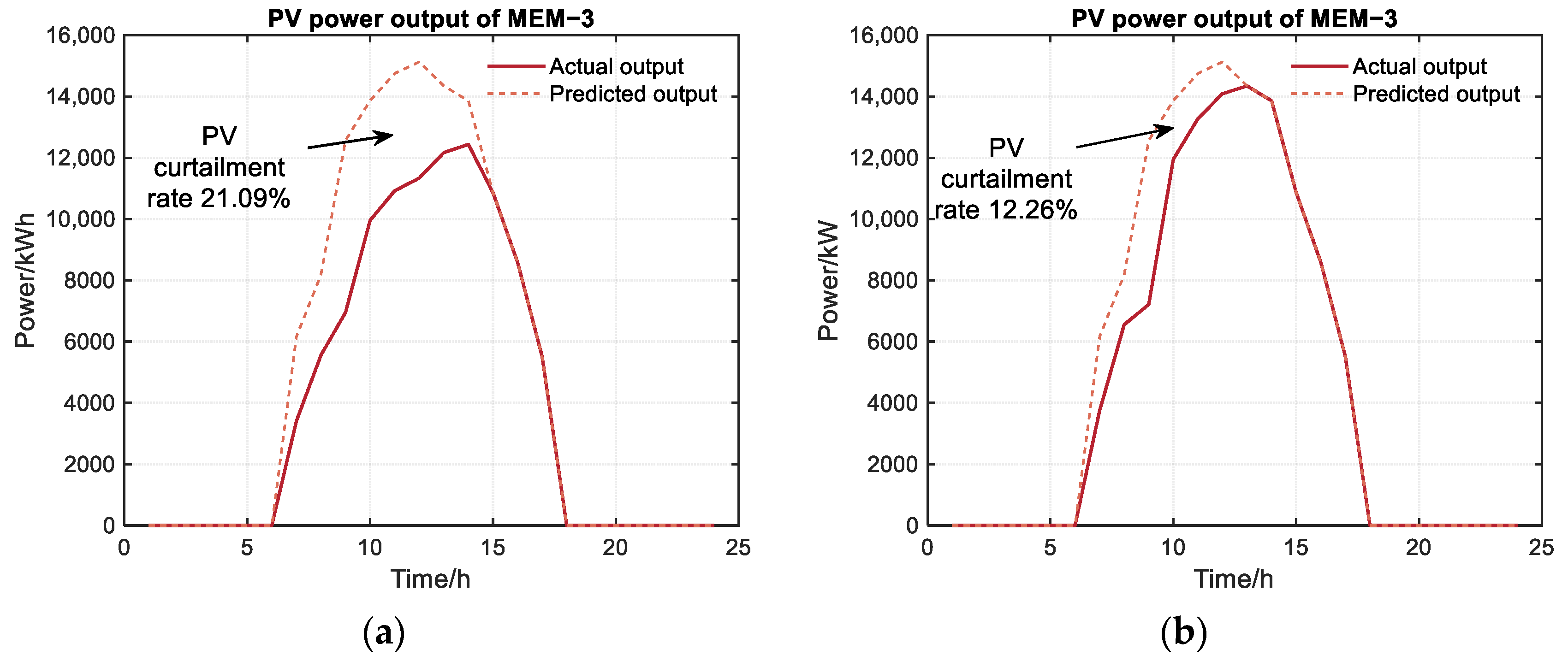
Figure 9, Figure 10 and Figure 11 compare the renewable energy consumption before and after the participation of the MMEMs in the cooperative game.
As illustrated in the figure, after participating in the cooperation, the renewable energy consumption rate of MEM-1, MEM-2, and MEM-3 increased by 8.34%, 8.78%, and 8.83%, respectively. This result demonstrated that the cooperative game facilitated effective electric energy sharing among the MMEMs, thereby improving the consumption rate of renewable energy.

5.2.4. Analysis of Renewable Energy Consumption Results

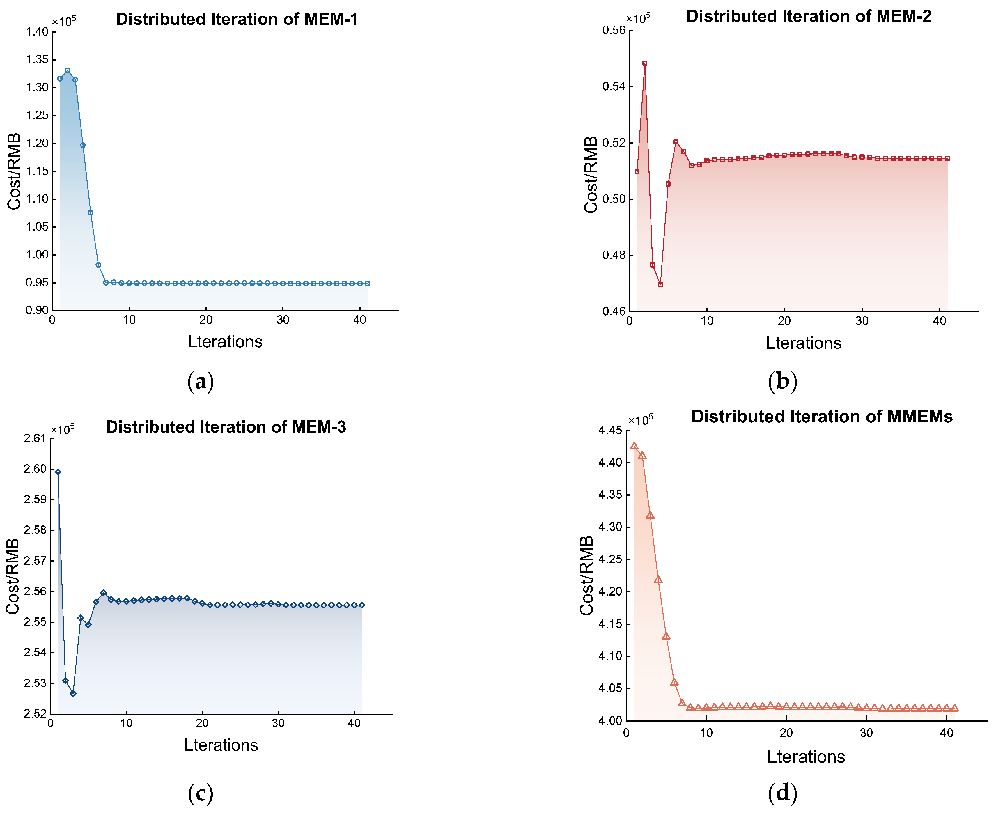
The iterative process of bargaining among the actors participating in the cooperative game is shown in Figure 12.
The proposed algorithm converged after 43 iterations with a convergence accuracy of 10−3, indicating that the Nash negotiation solution algorithm proposed based on ADMM exhibited a satisfactory convergence.

5.2.5. Analysis of Costs

Table 3 compares the operating costs of each entity before and after participating in the Nash negotiation; the income of each entity after participating in the cooperation increased, which met the basic conditions of Nash negotiation.
However, due to the large differences in the installed capacity scale, the cost structure, and the benefit evaluation of various entities, it is unfair to equally distribute the internal income distribution. For example, MEM-3 had stronger carbon-emission-reduction capabilities than the other units because it contained CCS and two-stage P2G units, so the bargaining power of each entity needs to be considered.
The distribution of the benefits considering bargaining power is shown in Table 4, and when considering the bargaining coefficient based on energy–carbon co-sharing capacity, an entity with a greater bargaining power will obtain a higher benefit distribution.
MEM-1 contributed the highest amount of electricity, but it also transmitted the most carbon dioxide to MEM-3, followed by MEM-2. Although MEM-3 did not contribute a substantial amount of electricity, it received carbon dioxide from MEM-1 and MEM-2. The bargaining coefficients of MEM-1 and MEM-2 were calculated to be 0.9172 and 0.8073, respectively, and MEM-3 had the highest bargaining coefficient of 1.2533, so MEM-3 could be allocated the largest yield.
Comparing the results in Table 3 and Table 4, it becomes evident that after considering the bargaining coefficient based on energy–carbon co-sharing capacity, MEM-3 with a CCS and a two-stage P2G could obtain higher returns than before, where the income value increased from RMB 3609.61 to RMB 12,047. This shows that the bargaining coefficient method based on energy–carbon co-sharing capacity is helpful in mobilizing the enthusiasm of all subjects to actively participate in the cooperative game.
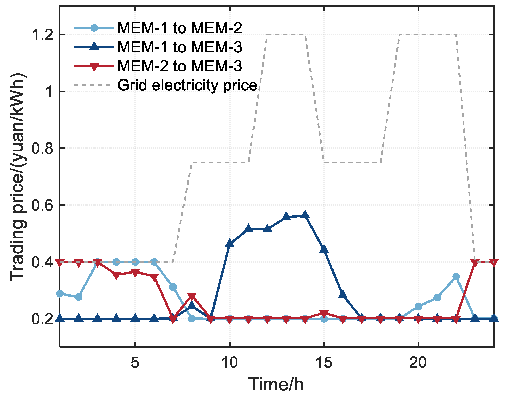
Figure 13 shows the electricity transaction price of each MEM after considering the bargaining coefficient of the energy–carbon co-sharing capability. It is apparent that the trading price of electricity between the MMEMs was lower than the purchasing price of electricity from the distribution network and higher than the price of selling electricity to the distribution network. As a result, each MEM preferred to sell electricity at a higher price than the price sold to the distribution network and purchase electricity at a lower price than the purchasing price from the distribution network.

6. Conclusions

Based on the Nash game theory, this paper studied the energy–carbon co-sharing optimization of MMEMs. An energy–carbon co-sharing operation model of MMEMs was established, and the model was decomposed into two sub-models, namely one that considered the maximization of benefits of an MEM alliance and another that considered the distribution of the cooperative income. The energy–carbon co-sharing contribution capacity of each participant was considered in the distribution of the cooperative income sub model. The primary conclusions are as follows:
  • Energy–carbon co-sharing among MMEMs facilitates the complementary and efficient utilization of resources. Through the cooperative games, the renewable energy consumption was enhanced, resulting in increased renewable energy consumption rates of 8.34%, 8.78%, and 8.83% for MEM-1, MEM-2, and MEM-3, respectively.
  • Energy–carbon co-sharing among MMEMs based on cooperative games can reduce the overall carbon emissions of MMEM alliances. The carbon emissions of each MEM in the case study were reduced to varying degrees, and the overall carbon emission reduction rate reached 17.81%, which proves that the energy–carbon co-sharing of MMEMs based on the Nash game is effective in reducing carbon emissions.
  • The Nash-negotiation-solving algorithm of the MMEM alliance based on ADMM had good convergence, and the convergence accuracy reached 10−3 while also considering the privacy protection of each subject.
  • The bargaining coefficient method based on energy–carbon co-sharing capacity is helpful in mobilizing the enthusiasm of all subjects to actively participate in the cooperative game. MEMs containing low-carbon units such as CCS and two-stage P2G units can achieve a fairer distribution of benefits compared to scenarios in which bargaining factors are not considered. Microgrids with higher renewable energy generation and more carbon capture can also obtain higher benefits in the energy–carbon co-sharing process.
In the future, further research can be conducted on games with various energy sources and explore more accurate and fair methods of benefit allocation. In addition, the refined modeling and capacity optimization configuration of carbon capture systems in microgrids can also be studied to minimize carbon emissions.

Author Contributions

Conceptualization, X.Y. and C.C.; methodology, C.C.; software, C.C. and G.Z.; validation, G.Z., H.M. and H.C.; formal analysis, C.C.; investigation, X.Y.; resources, X.Y.; data curation, G.Z.; writing—original draft preparation, X.Y. and C.C.; writing—review and editing, X.Y. and C.C.; visualization, H.M. and H.C.; supervision, X.Y. All authors have read and agreed to the published version of the manuscript.

Funding

This research received no external funding.

Data Availability Statement

Not applicable.

Conflicts of Interest

The authors declare no conflict of interest.

References

  1. Ayele, G.T.; Mabrouk, M.T.; Haurant, P.; Laumert, B.; Lacarriere, B. Optimal heat and electric power flows in the presence of intermittent renewable source, heat storage and variable grid electricity tariff. Energy Convers. Manag. 2021, 243, 114430. [Google Scholar] [CrossRef]
  2. Fan, W.; Ju, L.; Tan, Z.; Li, X.; Zhang, A.; Li, X.; Wang, Y. Two-stage distributionally robust optimization model of integrated energy system group considering energy sharing and carbon transfer. Appl. Energy 2023, 331, 120426. [Google Scholar] [CrossRef]
  3. Liu, Y.; Zuo, K.; Liu, X.; Liu, J.; Kennedy, J. Dynamic pricing for decentralized energy trading in micro-grids. Appl. Energy 2018, 228, 689–699. [Google Scholar] [CrossRef] [Green Version]
  4. Ju, L.; Tan, Z.; Yuan, J.; Tan, Q.; Li, H.; Dong, F. A bi-level stochastic scheduling optimization model for a virtual power plant connected to a wind-photovoltaic-energy storage system considering the uncertainty and demand response. Appl. Energy 2016, 171, 184–199. [Google Scholar] [CrossRef] [Green Version]
  5. Ma, T.; Wu, J.; Hao, L. Energy flow modeling and optimal operation analysis of the micro energy grid based on energy hub. Energy Convers. Manag. 2017, 133, 292–306. [Google Scholar] [CrossRef]
  6. Zhang, F.; Yang, Z.; Zhang, L.; Xu, Z. Optimal operation of islanded micro energy grid with multi-type demand responses. Power Syst. Technol. 2019, 44, 547–557. [Google Scholar]
  7. Chiş, A.; Koivunen, V. Coalitional game-based cost optimization of energy portfolio in smart grid communities. IEEE Trans. Smart Grid 2017, 10, 1960–1970. [Google Scholar] [CrossRef] [Green Version]
  8. Liu, N.; Yu, X.; Wang, C.; Li, C.; Ma, L.; Lei, J. Energy-sharing model with price-based demand response for microgrids of peer-to-peer prosumers. IEEE Trans. Power Syst. 2017, 32, 3569–3583. [Google Scholar] [CrossRef]
  9. Wang, S.; Ping, C.; Xue, G. Synergic Optimization of community energy internet considering the shared energy storage. Electr. Power. 2018, 51, 77–84. [Google Scholar]
  10. Wang, X.; Liu, J.; Shen, W. Non-cooperative game trading model for shared energy storage based on blockchain. J. Nanjing Univ. Inf. Sci. Technol. 2022, 14, 595–603. [Google Scholar]
  11. Shuai, X.; Ma, Z.; Wang, X. Optimal operation of shared energy storage and integrated energy microgrid based on leader-follower game theory. Power Syst. Technol. 2023, 47, 679–690. [Google Scholar]
  12. Maharjan, S.; Zhu, Q.; Zhang, Y. Demand Response Management in the Smart Grid in a Large Population Regime. IEEE Trans. Smart Grid 2015, 7, 189–199. [Google Scholar] [CrossRef]
  13. Wei, F.; Jing, Z.; Wu, P.; Wu, Q. A Stackelberg game approach for multiple energies trading in integrated energy systems. Appl. Energy 2017, 200, 315–329. [Google Scholar] [CrossRef]
  14. Lin, K.; Wu, J.; Liu, D.; Li, D.; Gong, T. Energy management optimization of micro energy grid based on hierarchical Stackelberg game theory. Power Syst. Technol. 2019, 43, 973–983. [Google Scholar]
  15. Kim, H.; Lee, J.; Bahrami, S. Direct energy trading of microgrids in distribution energy market. IEEE Trans. Power Syst. 2019, 35, 639–651. [Google Scholar] [CrossRef]
  16. Xu, Y.; Liu, H.; Sun, S.; Mi, L. Bi-level optimal scheduling of multi-microgrid system considering demand response and shared energy storage. Elec. Power Autom. Equip. 2023, 43, 1–25. [Google Scholar]
  17. Wu, J.; Lou, P.; Guan, M.; Huang, Y.; Zhang, W.; Cao, Y. Operation optimization strategy of multi-microgrids energy sharing based on asymmetric Nash bargaining. Power Syst. Technol. 2022, 46, 2711–2723. [Google Scholar]
  18. Chen, J.; Hu, Z.; Chen, Y.; Chen, Y.; Chen, W.; Gao, M.; Lin, M.; Du, Y. Thermoelectric optimization of integrated energy system considering ladder-type carbon trading mechanism and electric hydrogen production. Elec. Power Autom. Equip. 2021, 41, 48–55. [Google Scholar]
  19. He, L.; Lu, Z.; Zhang, J. Low-carbon economic dispatch for electricity and natural gas systems considering carbon capture systems and power-to-gas. Appl. Energy 2018, 224, 357–370. [Google Scholar] [CrossRef]
  20. Jiang, C.; Ai, X. Integrated energy system operation optimization model considering uncertainty of multi-energy coupling units. Power Syst. Technol. 2019, 43, 2843–2854. [Google Scholar]
  21. Nash, J.F., Jr. The bargaining problem. Econometrica 1950, 18, 155–162. [Google Scholar] [CrossRef]
  22. Ma, T.; Pei, W.; Xiao, H.; Li, D.; Lv, X.; Hou, K. Cooperative operation method for wind-solar-hydrogen multi-agent energy system based on Nash bargaining theory. Proc. CSEE 2021, 41, 25–39+395. [Google Scholar]
  23. Stephen, B.; Neal, P.; Eric, C.; Borja, P.; Jonathan, E. Distributed Optimization and Statistical Learning via the Alternating Direction Method of Multipliers. Found. Trends Mach. Learn. 2010, 3, 1–122. [Google Scholar]
  24. Liu, Y.; Zhang, N.; Zhang, X. Economic operation of Wind-PV-ES hybrid microgrid by considering of energy storage operational cost. Modern Electr. Power 2013, 30, 13–18. [Google Scholar]
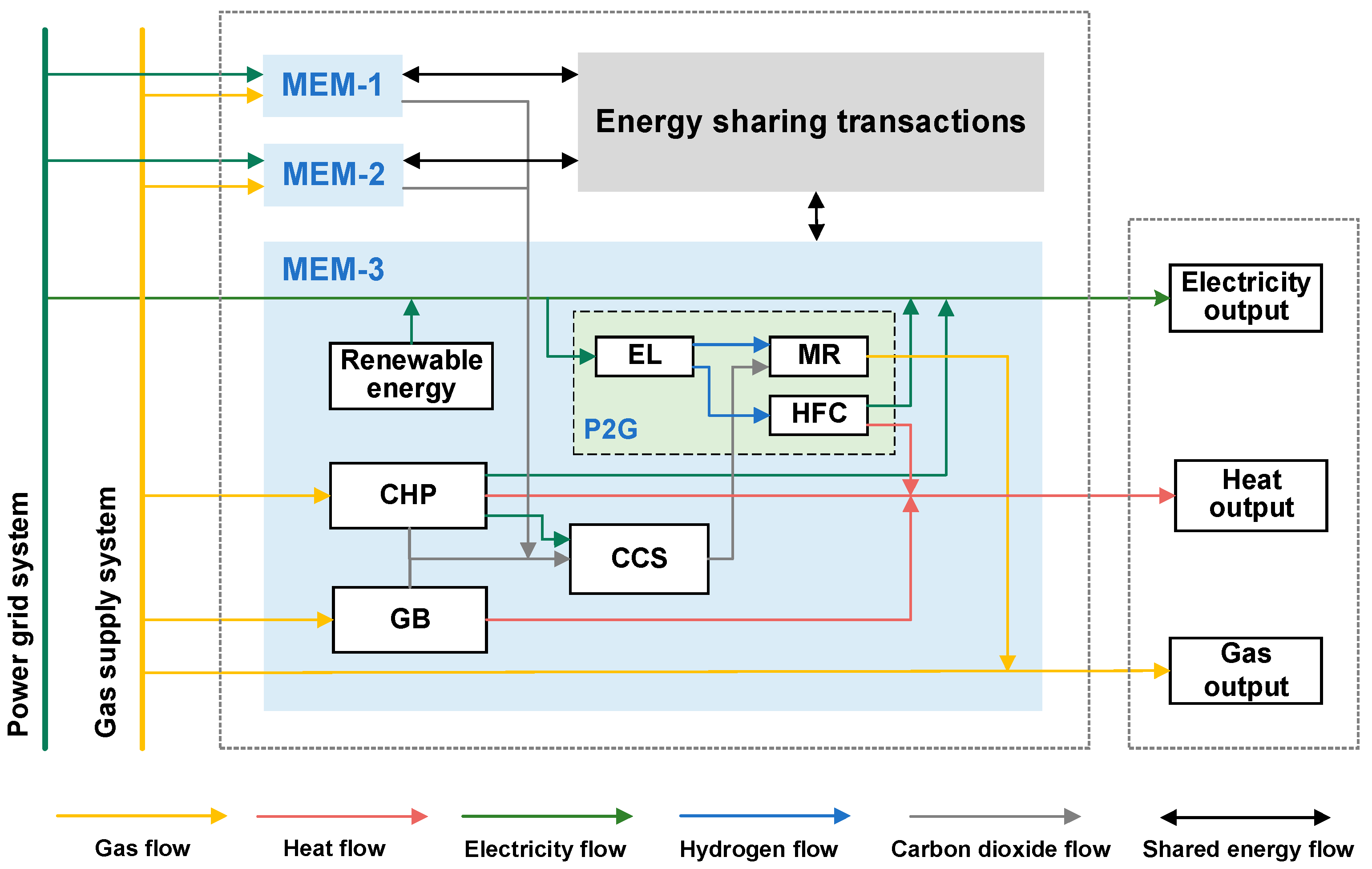
Figure 1. MMEM shared operation architecture.
Energies 16 05655 g001
Figure 2. Diagram of carbon sharing path.
Energies 16 05655 g002
Figure 3. Flow chart of ADMM algorithm.
Energies 16 05655 g003
Figure 4. Load and output curves of MMEMs: (a) MEM-1; (b) MEM-2; (c) MEM-3.
Energies 16 05655 g004
Figure 5. Electric power balance diagram of MMEM after cooperative game: (a) MEM-1; (b) MEM-2; (c) MEM-3.
Energies 16 05655 g005
Figure 6. Electrical energy interaction results between microgrids.
Energies 16 05655 g006
Figure 7. Carbon dioxide power balance of MMEMs after cooperative game: (a) MEM-1; (b) MEM-2; (c) MEM-3.
Energies 16 05655 g007
Figure 8. Carbon sharing results between MMEMs.
Energies 16 05655 g008
Figure 9. Comparison of renewable energy consumption in MEM-1 before and after the Nash negotiations: (a) before the Nash negotiations; (b) after the Nash negotiations.
Energies 16 05655 g009
Figure 10. Comparison of renewable energy consumption in MEM-2 before and after the Nash negotiations: (a) before the Nash negotiations; (b) after the Nash negotiations.
Energies 16 05655 g010
Figure 11. Comparison of renewable energy consumption in MEM-3 before and after the Nash negotiations: (a) before the Nash negotiations; (b) after the Nash negotiations.
Energies 16 05655 g011
Figure 12. Iterative convergence results of Sub-model 1: (a) MEM-1; (b) MEM-2; (c) MEM-3; (d) MMEMs.
Energies 16 05655 g012
Figure 13. Electric energy interaction results between microgrids.
Energies 16 05655 g013
Table 1. Parameters of model.
ParameterValue/kWParameterValue
P i , min e , e l , P i , max e , e l 0, 500 η e , e l 0.87
Δ P i , min e , e l , Δ P i , max e , e l −250, 250 η m r 0.6
P i , min H 2 , m r , P i , max H 2 , m r 0, 250 η e , h f c , η h , h f c 0.95, 2.1
Δ P i , min H 2 , m r , Δ P i , max H 2 , m r −125, 125 η e , c h p , η h , c h p 0.92, 2.1
P i , min H 2 , h f c , P i , max H 2 , h f c 0, 250 η g b 0.95
Δ P i , min H 2 , h f c , Δ P i , max H 2 , h f c −125, 125 η a b s , η r e l e a 0.95, 0.96
P i , min g , c h p , P i , max g , c h p 0, 600 μ i c 0.55
Δ P i , min g , c h p , Δ P i , max g , c h p −1000, 1000 σ c 0.9
P i , min g , g b , P i , max g , g b 0, 600 γ c c s 0.55
Δ P i , min g , g b , Δ P i , max g , g b −1000, 1000 k e , t r a n s 0.1
E min , E max 500, 2500 ς e , ς g 1.08, 0.234
P max g r i d , b u y , P max g r i d , s e l l 5000, 2000 α , β 0.5, 0.5
P max g , b u y 5000 ε 0.01
Table 2. Comparison of carbon emission results.
Carbon Emission Volume before Cooperation/kgCarbon Emission Volume after Cooperation/kgCarbon Emission Volume Reduction/%
MEM-1103,38191,50311.49%
MEM-2123,80886,53330.11%
MEM-399,82790,7429.10%
MMEMs327,016268,77817.81%
Table 3. Comparison of operating costs before and after participation in Nash negotiations.
EntitiesPre-Cooperation Costs/RMB *Post-Cooperation Costs/RMBRevenue Enhancement Value/RMB
MEM-1104,604.8294,851.479753.35
MEM-278,344.4551,462.2426,882.21
MEM-3259,168.68255,559.073609.61
MMEMs442,117.95401,872.78-
* The exchange rate of RMB to USD on 17 July 2023 was 1 RMB = 0.1385 USD.
Table 4. Distribution of benefits based on bargaining power.
EntitiesBargaining CoefficientBargaining Proceeds/RMBCost after Revenue Distribution/RMBThe Value of the Yield Enhancement after Considering the Bargaining Factor/RMB
MEM-10.91722341.2792,510.2012,094.62
MEM-20.8073−10,782.262,244.4416,100.01
MEM-31.25338437.39247,121.6812,047.00
Disclaimer/Publisher’s Note: The statements, opinions and data contained in all publications are solely those of the individual author(s) and contributor(s) and not of MDPI and/or the editor(s). MDPI and/or the editor(s) disclaim responsibility for any injury to people or property resulting from any ideas, methods, instructions or products referred to in the content.