Article

Thermodynamic Analyses of Sub- and Supercritical ORCs Using R1234yf, R236ea and Their Mixtures as Working Fluids for Geothermal Power Generation

1
National Key Laboratory of Petroleum Resources and Engineering, College of Mechanical and Transportation Engineering, China University of Petroleum, Beijing 102249, China
2
The Exploration and Development Research Institute of Huabei Oilfield Company, Renqiu 062552, China
*
Author to whom correspondence should be addressed.
Energies 2023, 16(15), 5676; https://doi.org/10.3390/en16155676
Submission received: 20 June 2023 / Revised: 21 July 2023 / Accepted: 25 July 2023 / Published: 28 July 2023
(This article belongs to the Special Issue Recent Advances in Organic Rankine Cycle)

Abstract

:
Organic Rankine cycles (ORCs) have been widely used to convert medium-low-temperature geothermal energy to electricity. Proper cycle layout is generally determined by considering both the thermo-physical properties of the working fluid and the geothermal brine temperature. This work investigates saturated, superheated and supercritical ORCs using R1234yf/R236ea for brine temperatures of 383.15 K, 403.15 K and 423.15 K. The evaporation and condensation pressures were optimized to maximize the net power outputs. The thermodynamic characteristics of the cycles at the optimal conditions were analyzed. The saturated ORCs produced slightly more net power than superheated cycles for the R1234yf mole fraction less than 0.2 due to lower exergy losses in the evaporator and condenser; however, the limited evaporation pressure by the turning point at the higher R1234yf mole fraction led to excessive exergy losses in the evaporator. Two R1234yf mole fractions maximized the net power and exergy efficiency in a superheated cycle, with the maximum net power output occurring at the R1234yf mole fraction of 0.8 for brine temperatures of 383.15 K and 403.15 K. The exergy losses for evaporation were reduced by 6–12.7% due to the use of an IHE, while those for condensation were reduced up to 42% in a superheated cycle for a brine temperature of 423.15 K, resulting in a 1–17.8% increase in the exergy efficiency. A supercritical cycle with an IHE using R1234yf/R236ea (0.85/0.15) generated the maximum net power output for a brine temperature of 423.15 K, 8.2–17.5% higher than a superheated cycle with an IHE.

1. Introduction

The efficient conversion of renewable energy, such as solar energy, geothermal energy and biomass energy, into electricity is a primary approach to reduce fossil fuel consumption and pollutant emissions. Geothermal energy has the distinctive features of being always stable, being unaffected by weather conditions, and having inherent storage capability [1,2]. Anderson et al. [3] depicted the highest aquifer temperatures at various locations on the earth, indicating that medium-low-temperature (<150 °C) geothermal resources account for a huge proportion. The organic Rankine cycle (ORC) shows great promise for low-enthalpy geothermal power generation and has been widely applied. Nevertheless, the thermal efficiencies for geothermal ORCs are generally lower than 12% due to lower heat source temperatures [4,5]. Therefore, improving the thermodynamic characteristics of geothermal ORCs has always been a research topic.
The selection of working fluid is crucial to improve ORC efficiency [6,7,8,9]. Zeotropic mixtures have attracted more attention in the ORC field due to the fascinating non-isothermal characteristics of the phase change process. Heberle et al. [10] compared the ORC economic performances of pure fluids with zeotropic mixtures. Their results showed that the best working fluid was a mixture with a fraction of isobutane of 0.9. Heberle et al. [11] further found that the exergy efficiencies were increased up to 20.6% using a zeotropic mixture of propane/isobutane compared to that using propane. However, the condensation heat transfer coefficient for the isobutane/isopentane mixture was reduced up to 18%, and the flow boiling heat transfer coefficient for the propane/isobutane mixture was decreased up to 48% due to an additional mass transfer during the phase change. Similar results were also discovered by Lecompte et al. [12]. Liu et al. [13] concluded that a geothermal ORC using isobutane/isopentane mixtures generated 4–11% more net power than that using pure isobutane, while the total heat transfer area per unit of power output was 30–40% higher. They also studied the effect of the condensation temperature glide of a zeotropic mixture on system performance [14]. Their results showed that the maximum net power was achieved when the condensation temperature glide was equal or close to the cooling water temperature rise [14]. Chys et al. [15] concluded that efficiency was increased by 16% when using a zeotropic mixture with a heat source temperature of 150 °C and by 6% with a heat source temperature of 250 °C. Wang et al. [16] found that a zeotropic mixture of hexane/toluene was the proper working fluid for a dual-loop ORC. Feng et al. [17] experimentally studied the thermodynamic characteristics of an ORC setup with a heating capacity of 80 kW using R245fa, R123 and their mixtures. Their experimental results showed that R245fa/R123 (0.67/0.33) had the highest thermal efficiency.
The thermo-physical properties of working fluids significantly influence cycle performance. Chen et al. [18] demonstrated that the critical temperature and the saturated vapor curve slope were vital properties for working fluid selection. Their results showed that isentropic and dry fluids were better suited for ORCs. Xu et al. [19] pointed out that the limit of thermal efficiency was related to the working fluid saturated vapor curve slope, vaporization latent heat and the specific heat capacity of superheated vapor. Shi et al. [20] revealed that working fluid with a higher critical temperature could better match the temperature profiles of heat transfer fluids during evaporation. Oyewunmi et al. [21] pointed out that pure working fluids appeared to be optimal for fulfilling low-temperature heat demands, while mixtures became optimal at higher heat demand temperatures. Quoilin et al. [22] demonstrated that plant efficiency could be increased by using higher-critical-temperature fluids. Miao et al. [23] proposed selection criteria for zeotropic mixtures for heat source temperatures between 393.15 K and 623.15 K. They provided two correlations describing optimal matching between working fluids and heat source fluids or coolant temperature profiles. In addition, they concluded that wet mixtures had relatively lower cycle efficiency compared to dry and isentropic fluids because a large superheat degree at the turbine inlet was needed. Yang et al. [24] revealed the mechanism of how system thermodynamics changed with certain working fluid property parameters. Braimakis et al. [25] pointed out that zeotropic mixtures could be considered when the heat source temperature was lower than the critical temperatures of the pure components.
Cycle layout is the key factor in the efficient conversion of geothermal energy into power. Generally, ORCs can be divided into subcritical saturated cycles, subcritical superheated cycles and supercritical cycles. Saturated ORCs (SAORCs) have been widely considered in the literature [11,26]. However, the saturated vapor may bring liquid droplets into the turbine, which may reduce the isentropic efficiency; therefore, superheated ORCs (SHORCs) with superheated vapor at the turbine inlet have also been adopted, although the thermodynamics may be reduced [27,28,29,30,31]. A supercritical ORC shows a potential increase in turbine power output due to better matching between the heat source fluid and the working fluid temperature profiles, but the higher turbine inlet pressure also leads to higher power consumption of the fluid pump [32,33]. Cycle layout design is affected by the thermodynamic properties of working fluids and heat source temperatures. Zhang et al. [34,35] pointed out that the turning-point temperature was the limit of a subcritical ORC with a conventional expander. Wang et al. [36] concluded that, when the working fluid temperature at the turbine inlet was greater than its turning point, a superheated or supercritical ORC should be employed to avoid liquid forming during expansion in the turbine. Meng et al. [37] pointed out that a proper cycle layout and its optimal operating parameters depended on the local geothermal fluid temperatures and dryness. Zhang et al. [38] found that a superheated ORC using a wet fluid promoted thermo-economic performance for a low-temperature heat source. However, a superheated ORC with an internal heat exchanger (IHE) using dry/isentropic fluids was recommended for a high-temperature heat source. Saleh et al. [39] recommended a subcritical saturated ORC with an internal heat exchanger using a dry fluid that had a higher critical temperature to obtain a higher thermal efficiency. They also found a decrease in the cycle thermal efficiency through the superheating of dry fluids at the turbine inlet. Li et al. [40] concluded that the use of an IHE showed a greater increase in the thermal efficiency of an ORC using a zeotropic mixture than that using pure fluid. They also pointed out that the increasing superheat degree at the turbine inlet led to a decrease in net power output but increases in thermal and exergy efficiencies. Fang et al. [41] found that the superheat degree reduced the net power and increased the electricity production cost (EPC) for a working fluid with a high critical temperature. Li et al. [42] pointed out that the efficiency of a regenerative ORC increased with increasing superheat degree, but the cycle did not always output more power with higher efficiency for waste heat recovery (WHR) application. They concluded that working fluids with a critical temperature 40–60 °C lower than the heat source temperature were preferred to output the maximum power. Song et al. [43] demonstrated that a working fluid with a higher critical temperature and lower dryness had a higher thermal efficiency. They also found that a wet working fluid was the preferred choice for a transcritical ORC.
Some of the literature has aimed at comparisons of various cycle layouts. Invernizzi et al. [44] analyzed subcritical and supercritical cycles based on the critical temperatures of working fluids. Their results showed that the thermal efficiency of a subcritical saturated cycle was higher than a supercritical cycle for fixed-heat-source thermal power. Zhang et al. [45] proposed an approach for selecting the optimal subcritical cycle layout with maximum plant exergy efficiency under saturation/superheating with/without an IHE cycle. They found that a saturated cycle with/without an IHE and a superheated cycle with an IHE were appreciable cycle layouts. Chen et al. [46] showed that optimal thermal efficiency could be gained using a saturated cycle or a superheated cycle with less superheating for a given temperature difference between the heat source and pinch point. Oyewunmi et al. [47] concluded that transcritical ORCs with regenerators generated more net power than subcritical cycles.
The geothermal brine temperature and the thermophysical properties of working fluids affect the selection and design of cycle layouts [48]. The turning-point temperature of a working fluid limits the application range of a saturated cycle. Moreover, when the evaporation temperature is close to the critical temperature, the change in temperature causes a drastic change in pressure, thus further limiting the range of subcritical cycles. In this work, the thermodynamic characteristics of R1234yf/R236ea zeotropic mixtures for various heat source temperatures and different cycle layouts are discussed. Based on temperature matching between the working fluid and the geothermal brine or cooling water, both the evaporation and condensation pressures are optimized to maximize the net power output. Furthermore, the effects of an internal heat exchanger (IHE) on the thermodynamic characteristics of the three cycles are analyzed. A cycle design criterion for R1234yf/R236ea zeotropic mixtures is proposed according to the optimization results.

2. Methodology

2.1. System Description

A schematic diagram of a geothermal simple ORC system with a wet cooling system is shown in Figure 1a, and an ORC with an IHE is illustrated in Figure 1b. The working fluid from the feed pump absorbs the heat released by the geothermal brine in the preheater and evaporator. According to the evaporation pressure and the state of the fluid at the turbine inlet, the ORC can be divided into three types, namely the subcritical saturated cycle, subcritical superheated cycle and supercritical cycle. Other processes of system circulation are not repeated. The IHE can recover the heat discharged from the turbine exhaust vapor and then preheat the fluid from the feed pump, thereby reducing irreversibility losses during condensation.
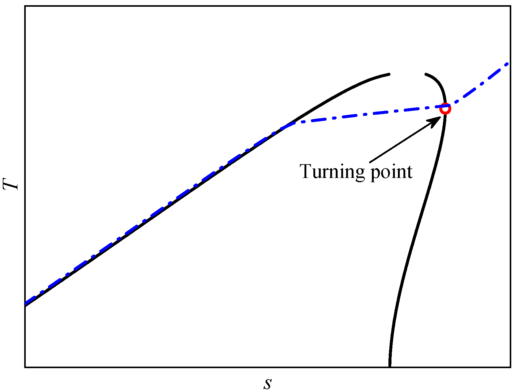
By virtue of their environmentally friendly characteristics, hydrofluoro-olefins (HFOs) have been widely used as alternative working fluids for ORCs [34]. In this work, R1234yf was selected as a component of the zeotropic mixture, and R236ea was selected as the other component. The point on the saturated vapor line with the maximum specific entropy is called the turning point, as shown in Figure 2 [34,35]. Figure 3 shows the parameters of the critical point, as well as the turning point, of R1234yf/R236ea mixtures of various mole fractions calculated using REFPROP 9.1.
The Ts diagram of the saturated cycle based on R1234yf/R236ea is shown in Figure 4a. The heat absorption process of the working fluid can be divided into preheating (4–5) and evaporation (5–1). The working fluid at the turbine inlet is dry, saturated vapor. The evaporation pressure in the saturated cycle is generally limited by the turning-point pressure to avoid the erosion of droplets on the turbine blades.
It is safe to overheat the working fluid at the turbine inlet in actual ORC operation [49,50]. Moreover, there is a turning point on the saturated vapor line for a dry or isentropic fluid. Therefore, superheating is needed when the heat source fluid temperature is much higher. The T-s diagram of a superheated ORC is shown in Figure 4b. The heat absorption process of the working fluid is divided into preheating (4–5), evaporation (5–1′) and superheating sections (1′–1). Considering the drastic pressure changes caused by temperature change in the near-critical region, it brings difficulties to ORC operation adjustment [12,51]. As a result, the upper limit of the evaporation pressure was set to 0.8pc, where pc is the critical pressure of the working fluid.
A T-s diagram of a supercritical ORC is shown in Figure 4c. The evaporation process (4–1) of the working fluid does not go through the two-phase region, and the evaporation pressure is higher than the critical pressure. Considering the thermo-physical properties of the working fluid in the near-critical region, the evaporation pressure was set above 1.05pc. The specific entropy of the working fluid at the turbine inlet was set to be greater than that at the turning point to avoid its expansion line passing through the two-phase region.

2.2. Thermodynamic Model

The heat released by the geothermal water is expressed as
Q ˙ EVA = m ˙ O ( h 1 h 4 ) = m ˙ H ( h H 1 h H 3 ) ,
where m ˙ O is the working fluid mass flow rate, h1 is the working fluid enthalpy at the evaporator outlet, h 4 is the working fluid enthalpy at the evaporator inlet, m ˙ H is the geothermal water mass flow rate, h H 1 is the geothermal water enthalpy at the evaporator inlet, and h H 3 is the geothermal water enthalpy at the evaporator outlet.
The power generated by the turbine is expressed as
W ˙ T = m ˙ O ( h 1 h 2 ) = m ˙ O ( h 1 h 2 s ) η T ,
where η T is the turbine isentropic efficiency, h2s is the turbine outlet enthalpy for the isentropic expansion process, and h2 is the real enthalpy at the turbine outlet.
The power consumed by the working fluid feed pump is expressed as
W ˙ FP = m ˙ O ( h 4 h 3 ) = m ˙ O ( h 4 s h 3 ) η FP ,
where η FP is the pump isentropic efficiency, h 3 is the working fluid enthalpy at the pump inlet, and h 4 s is the pump outlet enthalpy for the isentropic compression process.
A wet cooling system was adopted for the geothermal ORC. The power consumed by the circulating pump can be calculated using
W ˙ CP = m ˙ w g H η CP ,
where η CP is the circulating pump efficiency, m ˙ w is the cooling water flow rate, g is the gravitational acceleration, and H is the circulating pump head.
The cooling water mass flow rate can be calculated as
m ˙ w = Q ˙ CON Δ T cw c p ,
where Q ˙ CON is the heat flow during condensation, c p is the cooling water constant pressure specific heat, and Δ T cw is the cooling water temperature rise when being heated by the working fluid latent heat.
The net power output of the geothermal ORC system is
W ˙ net = W ˙ T η m η g W ˙ FP W ˙ CP ,
where η m is the turbine mechanical efficiency, and η g is the generator efficiency.
The specific exergy of a fluid at a certain state is
e = h h 0 T 0 ( s s 0 ) ,
where the ambient state is considered as the reference state, the ambient temperature T0 is set to 293.15 K, and the environmental pressure p0 is set to 0.1 MPa.
Exergy destruction in the evaporation process is defined as
I ˙ EVA = ( E ˙ H 1 E ˙ H 3 ) ( E ˙ 1 E ˙ 4 ) ,
exergy destruction in the condensation process is expressed as
I ˙ CON = E ˙ 2 E ˙ 3 + W CP ,
exergy efficiency of the evaporation process is expressed as
η ex , EVA = E ˙ 1 E ˙ 4 E ˙ H 1 E ˙ H 3 ,
end exergy efficiency of the ORC system is expressed as
η ex , sys = W ˙ net E ˙ H 1 ,

2.3. Determination of Pinch Point

2.3.1. Evaporation Process

The evaporation temperature of a working fluid is limited by the pinch point [51,52,53]. Due to the large heat capacity of geothermal water at a constant pressure, the pinch point in the evaporation process is generally located at the bubble point of the working fluid, which is the state point shown in Figure 5a. However, when the bubble point temperature of a working fluid approaches the critical temperature, the specific heat of the fluid increases while the vaporization latent heat decreases. The working fluid flow rate increases substantially due to the lower enthalpy rise during the heat absorption process, especially for an ORC with an IHE; thus, the pinch point appears in the preheating section [51,53] (liquid phase), as shown in Figure 5b. Therefore, the preheating section can be divided into n sections (n = 50) based on heat transfer, as shown in Figure 5b, to accurately determine the pinch-point temperature difference between the geothermal brine and the working fluid. Assuming an evaporation pressure, the temperature difference is then calculated between the geothermal brine and working fluid for each section. The pinch-point position and the optimal evaporation pressure can be obtained through iteration. The pinch point is generally located inside the evaporator for a supercritical cycle, as shown in Figure 5c. The entire heat transfer process should be divided into n sections (n = 100), as shown in Figure 5c, and the evaporation pressure and turbine inlet temperature are simultaneously optimized.

2.3.2. Condensation Process

The cooling water temperature rise corresponding to the condensation section of the working fluid was set to be 5 K, and the pinch-point temperature difference in the condenser was 5 K, as shown in Table 1. First, assuming a condensation pressure, the specific enthalpy and the dew point of the condensation could be determined. The heat transfer process was evenly divided into n segments (n = 50). The temperature difference between the working fluid and the cooling water for each segment was calculated to determine the minimum temperature difference.
The pinch-point location is related to the cooling water temperature rise Δ T cw and the condensation temperature glide Δ T glide , where
Δ T cw = T W 2 T W 1 ,
Δ T glide = T 2 T 3 ,
The pinch point during condensation appears at the bubble point of the mixture working fluid when Δ T glide is much higher than Δ T cw . When Δ T glide approximately equals Δ T cw , the pinch-point location occurs either at the bubble point or the dew point of the mixture working fluid if the condensation curve presents a convex shape, as shown in Figure 6a. The pinch point occurs within the condenser when the condensation curve is concave downward, as shown in Figure 6b. The pinch point appears at the dew point when Δ T glide is much smaller than Δ T cw , as shown in Figure 6c.

2.4. Boundary Conditions and Parameter Optimization

The cycle modeling assumptions are summarized in Table 1. The inlet temperature of the geothermal brine ranged from 383.15 K to 423.15 K with an increment of 20 K, and the brine reinjection temperature should be not less than 343.15 K to avoid scale formation [53]. The reduced evaporation pressure should be lower than 0.8 for a subcritical cycle to avoid the drastic pressure variations caused by temperature change in the near-critical region and higher than 1.05 for a supercritical cycle to avoid the computing complexity of thermophysical properties in the near-critical region. The superheating was assumed to be no less than 5 K for a superheated cycle. An IHE could be used to preheat the working fluid when the turbine exhaust temperature was much higher. The temperature drop of the exhaust vapor in the IHE should be greater than 5 K.
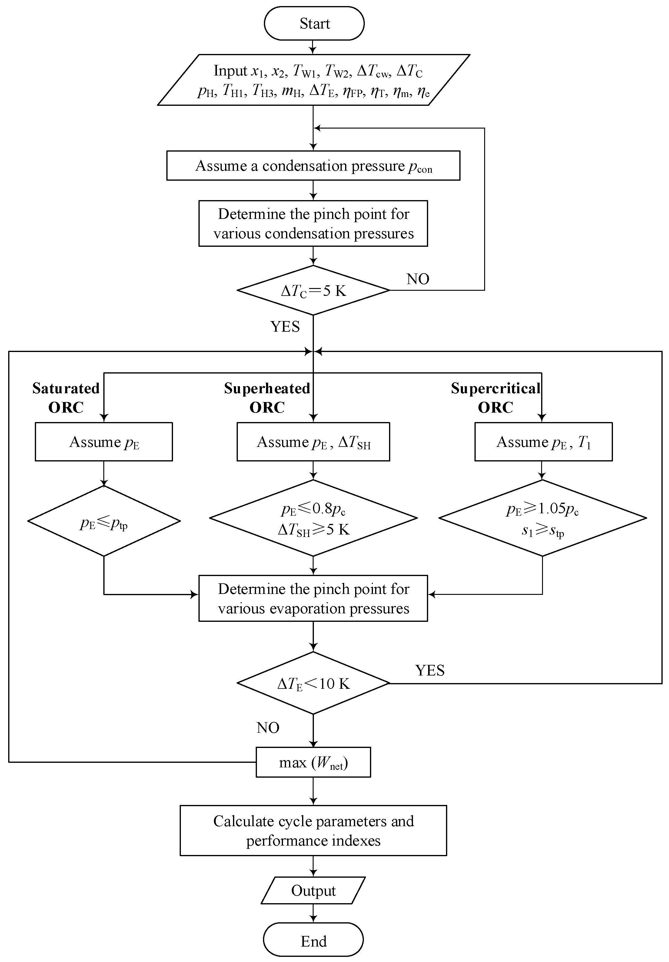
A flow chart of the optimization method is depicted in Figure 7. The mole fractions of R1234yf ranged from 0 to 1 with an increment of 0.1. The thermodynamic properties of the working fluids were calculated using REFPROP 9.1.

3. Results and Discussion

3.1. Parametric Optimization

The working fluid condensation pressure should be lower to produce maximum power. As mentioned in Section 2.3.2, the condensation region of the mixture working fluid was divided into 50 sections with equal heat flow intervals. The condensation pressures were determined with a temperature difference between the mixture and the cooling water of no less than 5 K for each section. Figure 8 shows the optimal condensation pressures of R1234yf/R236ea for various R1234yf mole fractions. As the R1234yf mole fraction increased, the condensation pressure increased gradually. For a given mixture mole fraction, the condensation pressures for the cycles were the same, but the cooling water mass flow rates varied with the working fluid flow rates.

3.1.1. Evaporation Pressure

Figure 9 shows the optimized reduced evaporation pressures of R1234yf/R236ea mixtures for subcritical and supercritical ORCs. The dotted line represents the reduced pressures at the turning point (pr,tp) for various mole fractions. The reduced pressure at the turning point decreased from 0.64 to 0.45 with increasing R1234yf mole fraction. The optimal reduced evaporation pressures of the saturated cycles increased as the R1234yf mole fraction (xR1234yf) increased for x R 1234 yf 0.65 when the geothermal brine inlet temperature was 383.15 K. The R1234yf/R236ea mixtures with higher R1234yf mole fractions had much lower critical temperatures. Therefore, the evaporation pressures for saturated ORCs using mixtures with lower critical temperatures were limited at the pressure of the turning point for high heat source temperatures. For example, the reduced evaporation pressures of the saturated cycles should maintain the reduced pressures at the turning points for x R 1234 yf 0.65 and a geothermal brine inlet temperature of 383.15 K. The optimal evaporation pressure for the saturated cycles increased with increasing geothermal brine inlet temperature. However, the reduced evaporation pressures of the saturated cycles should remain at the reduced pressures at the turning points for x R 1234 yf 0.45 when the geothermal brine inlet temperature was 403.15 K, as well as for x R 1234 yf 0.2 when the brine temperature was 423.15 K.
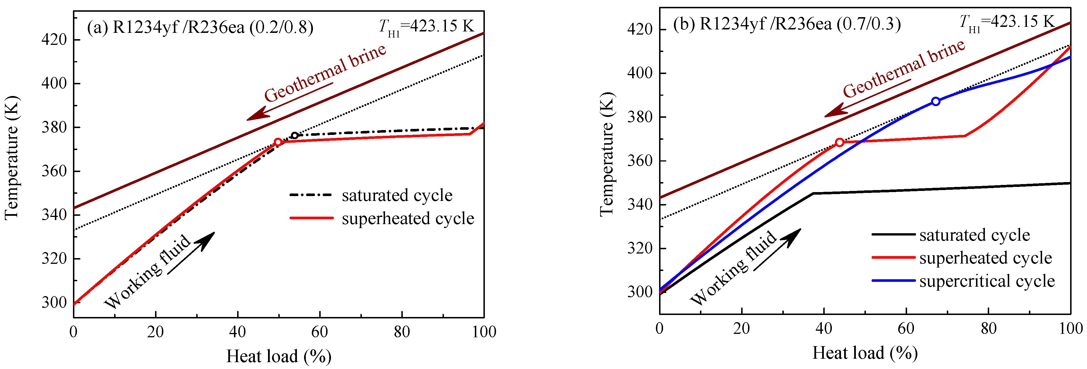
The evaporation pressures for superheated cycles were optimized for various R1234yf mole fractions with superheating degrees of no less than 5 K. The working fluid flow rate of superheated ORCs was lower than that of saturated cycles due to superheating, which led to the changes in the preheating and evaporating heat loads. Thus, the evaporation pressure for the superheated cycle was lower than that for the saturated cycle due to the pinch-point temperature difference limit, as shown in Figure 10a. The reduced evaporation pressure for the superheated cycle increased as the R1234yf mole fraction increased for the geothermal brine inlet temperature of 383.15 K but was slightly lower than that for the saturated cycle for x R 1234 yf 0.6 , as shown in Figure 9a. The evaporation pressure of the R1234yf/R236ea mixture increased as the geothermal brine inlet temperature increased to boost the cycle power output. However, the reduced evaporation pressures remained at the upper limit, which was set to 0.8 for x R 1234 yf 0.75 when the geothermal brine temperature was 403.15 K and, for x R 1234 yf 0.4 , when the geothermal brine temperature was 423.15 K. The superheat vapor temperatures were also optimized when the reduced evaporation pressures equaled 0.8. The heat flow for superheating increased while the heat flow to the evaporator decreased, which led to better matching of the zeotropic mixture and brine temperature profiles, as shown in Figure 10b.
Since the critical temperatures of the R1234yf/R236ea mixtures with R1234yf mole fractions greater than 0.5 were extremely lower, a supercritical cycle could be adopted for a geothermal brine inlet temperature of 423.15 K. The supercritical ORC using the R1234yf/R236ea mixture as working fluid provided a better match between the temperatures of the working fluid and the geothermal brine than the subcritical cycle, as seen in Figure 10b. The optimal reduced evaporation pressure of the supercritical cycle increased from 1.15 to 1.49 as the R1234yf mole fraction increased from 0.5 to 0.9, as shown in Figure 9c.

3.1.2. Turbine Inlet Temperature

The turbine inlet temperatures of R1234yf/R236ea mixtures for subcritical and supercritical ORCs are shown in Figure 11. The turbine inlet temperature of the saturated cycle varied with the evaporation pressure, which first increased as the R1234yf mole fraction increased and then decreased when the evaporation pressure remained at the turning point. Note that the minimum temperature difference between the brine and the working fluid was higher than 10 K when the evaporation pressure was limited at the turning point for the saturated cycle, as shown in Figure 10b. The turbine inlet temperature of the superheated cycle was higher than that of the saturated cycle, especially for a higher R1234yf mole fraction. A higher superheating degree reduces the cycle power output for a low-temperature heat source [27,28]. The temperature rises in the superheater were maintained at 5 K for a brine temperature of 383.15 K. The temperature glide first increased as the R1234yf mole fraction increased and then decreased. Therefore, the turbine inlet temperature of the superheated cycle also first increased with increasing R1234yf mole fraction for x R 1234 yf 0.5 and then slightly decreased when the geothermal brine inlet temperature was 383.15 K. Since the evaporation pressure remained at 0.8pc for a higher R1234yf mole fraction when the geothermal brine inlet temperature was 403.15 K, as shown in Figure 9b, the turbine inlet temperature of the superheated cycle rapidly increased for x R 1234 yf 0.75 , as shown in Figure 11b, which resulted in better matching between the brine and the working fluid temperatures. The turbine inlet temperature of the superheated cycle first increased with increasing R1234yf mole fraction and remained at 413.15 K for x R 1234 yf > 0.7 when the geothermal brine inlet temperature was 423.15 K, as shown in Figure 11c. Note that the pinch points were only located at the superheater outlet for x R 1234 yf > 0.7 . The optimal turbine inlet temperature of the supercritical cycle also increased as the R1234yf mole fraction increased.

3.2. Net Power Output

The net power outputs of the subcritical and supercritical cycles at the optimal conditions for various brine temperatures are shown in Figure 12. The R1234yf/R236ea mixtures with lower R1234yf mole fractions had high critical temperatures. The net power generated by the saturated cycle was higher than that by the superheated cycle using a R1234yf/R236ea mixture with a lower R1234yf mole fraction. The superheating increased the turbine inlet temperature and the specific enthalpy drop in the turbine but reduced the working fluid flow rate, resulting in a decrease in the net power output. The saturated cycle generated 1.1–1.3% more turbine power than the superheated cycle for R1234yf mole fractions less than 0.6 and a brine temperature of 383.15 K, but the working fluid feed pump consumed 4.5–6% more power due to the higher evaporation pressure and working fluid flow rate. Meanwhile, the circulating pump power consumption was increased by 2.8–3.5%. Thus, the net power output of the saturated cycle was 0.4–0.95% higher than that of the superheated cycle, as shown in Figure 12a. For R1234yf mole fractions higher than 0.6, the evaporation pressures of the saturated cycle were limited by the turning point, which resulted in a larger temperature difference between the brine and the working fluid. The evaporation temperature of the superheated cycle was higher than that of the saturated cycle, as shown in Figure 11a; thus, the superheated cycle produced more net power than the saturated cycle. The turbine power output in the superheated cycle was 5.5% higher for an R1234yf mole fraction of 0.7 and 46% higher for an R1234yf mole fraction of 0.95 than that in the saturated cycle because the evaporation temperature of the saturated cycle decreased with increasing R1234yf mole fraction. The working fluid pump in the superheated cycle consumed more power than that in the saturated cycle due to the higher evaporation pressure, but the cooling water circulating pump consumed 5–8% less power. Thus, the increase in the net power output for the superheated cycle relative to the saturated cycle increased from 6.7% to 52.3% as the R1234yf mole fraction increased from 0.7 to 0.95. Two local maxima appear in the net power output of the superheated cycle, as shown in Figure 12a, which were obtained when the R1234yf mole fractions were 0.1 and 0.8, respectively. Similar conclusions can be found in [14,50]. The superheated cycle using R1234yf/R236ea (0.8/0.2) produced a maximum net power of 668.2 kW for the brine inlet temperature of 383.15 K, which was 8.96% higher than that using pure fluid R236ea and 5.9% greater than that using R1234yf.
The saturated cycle output 1.1–1.5% more net power than the superheated cycle for x R 1234 yf 0.4 and the brine temperature of 403.15 K, as shown in Figure 12b. The saturated cycle produced the maximal net power using the working fluid with an R1234yf mole fraction of 0.1, which was 1160.7 kW. The net power output by the saturated cycle decreased as the R1234yf mole fraction increased for x R 1234 yf > 0.45 because the turbine inlet temperature decreased. The saturated cycle using R1234yf/R236ea (0.9/0.1) produced 38.5% less power than that using R1234yf/R236ea (0.1/0.9) due to the large temperature difference between the brine and the working fluid caused by the evaporation pressure limit. However, the turbine inlet temperature of the superheated cycle increased as the R1234yf mole fraction increased, as shown in Figure 11b. Therefore, the superheated cycle output more net power than the saturated cycle for R1234yf mole fractions higher than 0.45. Because the evaporation pressure remained at 0.8pc when the R1234yf mole fraction was greater than 0.75, the turbine inlet temperature increased sharply with a larger superheating degree to better match the temperature profiles between the brine and the working fluid. Two R1234yf mole fractions maximized the net power output of the superheated cycle. The superheated cycle with R1234yf/R236ea (0.8/0.2) produced the maximum net power of 1206.7 kW, which was 11.09% higher than that with R236ea and 10.84% higher than that with R1234yf.
The net power generated by the saturated cycle was 1.7–2.1% higher than the superheated cycle for R1234yf mole fractions lower than 0.2 when the brine temperature was 423.15 K, as shown in Figure 12c. However, the increase in the net power output by the superheated cycle relative to the saturated cycle increased from 1.8% to 79.4% as the R1234yf mole fraction increased from 0.25 to 0.95. The superheated cycle with R1234yf/R236ea (0.4/0.6) generated the maximal net power, which was 4.6% higher than that with R236ea and 23.5% higher than that with pure R1234yf. The evaporation pressure of the superheated cycle was limited to 0.8pc for R1234yf mole fractions higher than 0.45, and the working fluid was heated to a higher temperature in the superheater by the brine, as seen in Figure 11c, which led to a higher turbine exhaust temperature. The cycle thermal efficiency decreased due to the larger cold source losses in the condenser caused by the higher turbine exhaust temperature. Therefore, the net power output of the superheated cycle decreased gradually with increasing R1234yf mole fraction for x R 1234 yf > 0.45 . Supercritical ORCs were considered for working fluids with low critical temperatures. Since the evaporation pressure of the supercritical cycle was much higher than that of the subcritical cycle, the turbine in the supercritical cycle produced more power than that in the superheated cycle. The turbine power produced by the supercritical cycle was 12–44.9% higher than that of the superheated cycle for R1234yf mole fractions between 0.5 and 1. However, the working fluid pump in the supercritical cycle consumed 67.8–185% more power than that in the superheated cycle due to the higher evaporation pressure and working fluid flow rate. The circulating pump power consumption for the supercritical cycle was also 10.3–19.4% higher than that for the superheated cycle due to the higher cooling water flow rate. The increase in the net power output of the supercritical cycle relative to the superheated cycle increased from 6.06 to 27% as the R1234yf mole fraction increased from 0.5 to 0.95. The supercritical cycle using R1234yf/R236ea (0.85/0.15) produced the maximum net power.

3.3. Exergy Analysis

Figure 13 shows the exergy destruction during evaporation for brine temperatures of 383.15 K, 403.15 K and 423.15 K. The exergy destruction in the preheater and the evaporator of the saturated cycle was slightly lower than the superheated cycle for lower R1234yf mole fractions because of the higher average evaporation temperature, as seen in Figure 10a. When the evaporation pressure for the saturated cycle was limited by the turning point for higher R1234yf mole fractions, the temperature difference between the brine and the working fluid increased. Therefore, the exergy losses during evaporation in the saturated cycle sharply increased, as shown in Figure 13. Because the dew point temperature of the turning point decreased as the R1234yf mole fraction increased, the average evaporation temperature decreased, which resulted in a larger temperature difference between the brine and the working fluid. Thus, the exergy destruction during evaporation for the saturated cycle increased with increasing R1234yf mole fraction. The exergy destruction rate for the saturated cycle increased from 17.8% to 27.9% as the R1234yf mole fraction increased from 0.65 to 0.95 for the brine temperature of 383.15 K, while it increased from 22.2% to 43.6% for the brine temperature of 423.15 K. The larger irreversibility losses during evaporation for the saturated cycle led to a lower net power output. As the R1234yf mole fraction increased, the exergy destruction during evaporation for the superheated cycle slightly decreased for x R 1234 yf 0.4 , then increased for 0.4 < x R 1234 yf 0.8 since the temperature glide decreased, and finally, decreased for x R 1234 yf > 0.8 when the brine temperature was 383.15 K. The irreversibility losses during evaporation for the superheated cycle decreased with increasing R1234yf mole fraction because the temperature difference between the brine and the working fluid decreased for the brine temperature of 403.15 K. Both the minimum temperature differences between the brine and the working fluid in the preheater and the evaporator were higher than 10 K for R1234yf mole fractions higher than 0.75 when the brine temperature was 423.15 K; thus, the exergy losses during evaporation for the superheated cycle increased, as shown in Figure 13c. The exergy losses during evaporation for the supercritical cycle were lower than those of the superheated cycle due to better matching of the mixture and brine temperature profiles. The turbine inlet temperature increased with increasing R1234yf mole fraction, as shown in Figure 11c; thus, the exergy destruction rate during evaporation for the supercritical cycle decreased from 15.9% to 13.3% as the R1234yf mole fraction increased from 0.5 to 0.95.
Figure 14 shows the exergy destruction during condensation as a function of the R1234yf mole fraction for various brine temperatures. As the R1234yf mole fraction increased, the exergy losses first decreased and reached a minimum at x R 1234 yf = 0.1 since the temperature difference between the working fluid and the cooling water decreased. When the condensation temperature glide was higher than the cooling water temperature rise, which resulted in a bigger temperature difference between the working fluid and the cooling water, the exergy losses in the condenser began to increase and reached a maximum at x R 1234 yf = 0.4 . When the condensation temperature glide began to decrease with increasing R1234yf mole fraction, the exergy losses then decreased and reached the other minimum at x R 1234 yf = 0.8 with decreasing temperature difference between the working fluid and the cooling water; they then increased because the temperature difference between the working fluid and the cooling water began to increase. Two local minima appeared in the exergy destruction for the saturated cycle when the condensation temperature glide was nearly equal to the cooling water temperature rise, with the lower minimum at a higher R1234yf mole fraction due to the lower turbine exhaust temperature. The condensation pressures for the three cycles were the same for a given R1234yf mole fraction. However, the irreversibility losses in the condenser also depended on the working fluid flow rate and the turbine exhaust temperature. When the brine temperature was 383.15 K, the exergy losses during condensation of the superheated cycle were higher than those of the saturated cycle for R1234yf mole fractions lower than 0.85 due to the higher turbine exhaust temperature, while the exergy destruction rate was slightly lower since the lower working fluid mass flow rate resulted in less heat transferred to the cooling water in the condenser. The vapor in the superheater was heated to higher temperatures for higher R1234yf mole fractions when the brine temperatures were 403.15 K and 423.15 K, which led to a higher turbine exhaust temperature; thus, the exergy losses during condensation in the superheated cycle sharply increased, as shown in Figure 14b,c. The working fluid flow rate of the supercritical cycle was lower than that of the saturated cycle, but the turbine exhaust temperature was higher. Therefore, the exergy destruction in the condenser for the supercritical cycle was slightly lower than that of the saturated cycle for R1234yf mole fractions less than 0.6 but was higher for R1234yf mole fractions higher than 0.6.
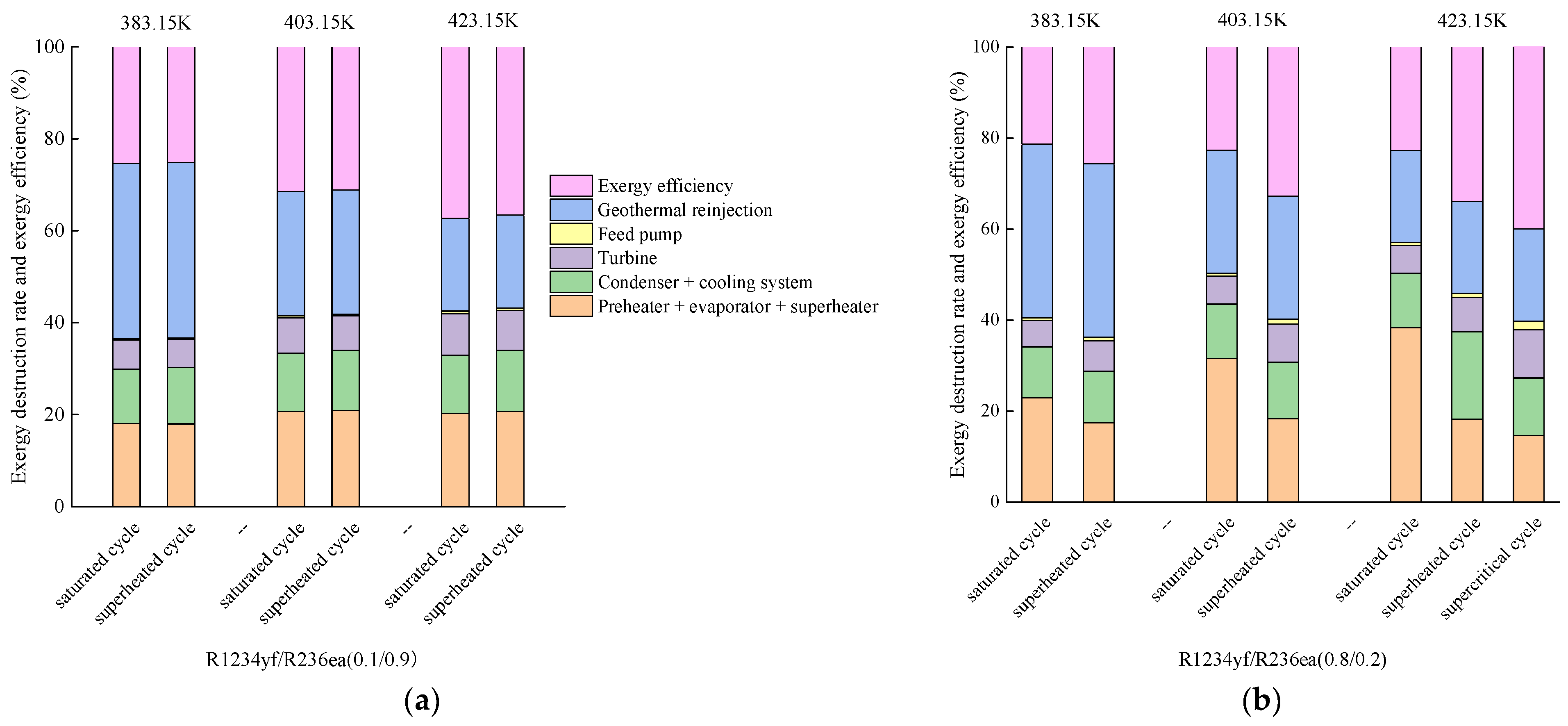
Figure 15 shows the exergy destruction rates of R1234yf/R236ea (0.1/0.9) and R1234yf/R236ea (0.8/0.2) for various brine temperatures. The exergy destruction rates of brine reinjection for the three cycles were the same for a given heat source because of the same reinjection temperature. The exergy destruction rate caused by brine reinjection decreased to 20.2% for the brine temperature of 423.15 K from 38.1% for the brine temperature of 383.15 K. The exergy destruction rate for evaporation increased from 18% to 20.2% as the brine temperature increased from 383.15 K to 423.15 K for the saturated cycle using R1234yf/R236ea (0.1/0.9). The exergy losses during condensation accounted for 11.9–12.7% of the geothermal exergy input. The exergy destruction rates for condensation and evaporation in the saturated cycle were slightly lower than those in the superheated cycle, but the exergy destruction rate of the turbine was higher. It can be seen that the working fluid of R1234yf/R236ea (0.1/0.9) with a higher critical temperature had the optimal evaporation pressure below the turning point, and the exergy efficiency of the saturated cycle was slightly higher than that of the superheated cycle. The evaporation pressure for the saturated cycle using R1234yf/R236ea (0.8/0.2) with a lower critical temperature was limited by the turning point. The exergy destruction rate for evaporation was 31.7% higher than that of the superheated cycle for the brine temperature of 383.15 K and 110.7% higher for the brine temperature of 423.15 K. Although the exergy losses in the condenser, turbine and feed pump in the saturated cycle were less than those in the superheated cycle, the exergy efficiency of the saturated cycle was lower than that of the superheated cycle using R1234yf/R236ea (0.8/0.2). The supercritical cycle with R1234yf/R236ea (0.8/0.2) had the highest exergy efficiency due to the lowest exergy destruction rate for evaporation.

3.4. Effect of IHE

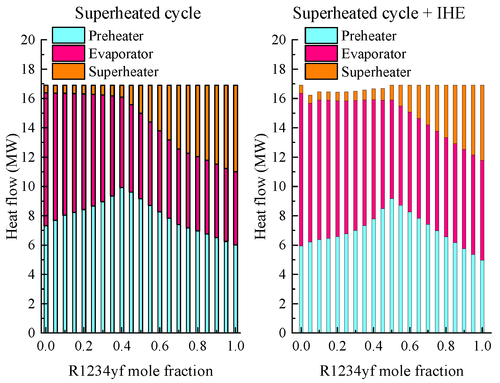
Taking the geothermal brine inlet temperature of 423.15 K as an example, the effects of an IHE on the thermodynamic characteristic of the superheated and supercritical cycles were analyzed. The working fluid was preheated using the turbine exhaust in the IHE, which affected the temperature rise in the preheater, evaporator and superheater, as shown in Figure 16. The working fluid temperature could be increased by 10–23 K in the IHE for the superheated cycle. The optimal evaporation pressure for the superheated cycle with the IHE was lower than that for the superheated cycle for x R 1234 yf < 0.45 due to the temperature increase in the IHE, while the evaporation pressure remained at 0.8pc for x R 1234 yf 0.45 . The preheater outlet temperature (bubble-point temperature) accordingly decreased for x R 1234 yf < 0.45 . Thus, the working fluid temperature rise in the preheater was decreased by 12–23 K for the superheated cycle with the IHE, as seen in Figure 16a. The preheating heat flow was reduced by 19–22% using the IHE for R1234yf mole fractions less than 0.45 due to the decrease in the brine temperature at the preheater inlet and the increase in the reinjection temperature, as shown in Figure 17. However, the heat flow for the preheating of the superheated cycle with the IHE was equal to that of the superheated cycle for 0.5 x R 1234 yf 0.7 because the brine temperatures at the preheater inlet and outlet for both cycles were the same and were limited by the pinch-point location (bubble point) and the evaporation pressure (0.8pc). The use of an IHE reduced the preheating heat flow by up to 12% for x R 1234 yf > 0.7 . The exergy losses in the preheater were reduced by 31–40% for x R 1234 yf < 0.45 , by 25–38% for 0.5 x R 1234 yf 0.7 , and by 44–62% for x R 1234 yf > 0.7 due to the use of the IHE, as shown in Figure 18a. The working fluid temperature rise in the evaporator (temperature glide) for the superheated cycle with the IHE was increased by 0.2 K for the R1234yf mole fraction of 0.1 and by 0.9 K for the R1234yf mole fraction of 0.4; however, the temperature rise for evaporation was not changed for x R 1234 yf 0.5 . The increase in the evaporation heat flow for the superheated cycle with the IHE relative to the superheated cycle increased from 9% for the R1234yf mole fraction of 0.05 to 32% for the R1234yf mole fraction of 0.4 due to the increases in the working fluid flow rate and the evaporation latent heat, while it increased from 17% for the R1234yf mole fraction of 0.5 to 36.4% for the R1234yf mole fraction of 0.95, as shown in Figure 17. The exergy losses in the evaporator were correspondingly increased by 17.3–61.6% using the IHE for R1234yf mole fractions less than 0.4, while the losses were increased by 26.3–54.5% for R1234yf mole fractions higher than 0.45, as shown in Figure 18a. The use of an IHE did not change the superheating degree (temperature rise in the superheater) for x R 1234 yf 0.4 . Note that the temperature rise in the superheater of the superheated cycle with the IHE was 3.8 K lower for the R1234yf mole fraction of 0.45 and up to 23 K lower for x R 1234 yf 0.7 than that of the superheated cycle. The superheating heat flow was slightly increased by the IHE for R1234yf mole fractions less than 0.2, but the heat flow was decreased by 38–41% for 0.5 x R 1234 yf 0.7 , as shown in Figure 17. The exergy losses in the superheater were increased by 10.7–17.4% due to the use of the IHE for R1234yf mole fractions less than 0.4 and were increased by 11.3–26.9% for R1234yf mole fractions higher than 0.75, as shown in Figure 18a. The total exergy losses in the preheater, evaporator and superheater were reduced by 6–12.7% by the IHE for the superheated cycle.
The use of the IHE increased the working fluid temperature by 6.4–13.2 K for the supercritical cycle, as shown in Figure 16b, but decreased the optimal turbine inlet temperature by 5.1–7.9 K. The temperature rise in the evaporator was decreased by 11.3–20.6 K due to the use of the IHE, which resulted in a 4.3–11.1% increase in the working fluid mass flow rate. The average temperature difference between the brine and the working fluid was decreased by the IHE for the supercritical cycle; thus, the exergy losses in the evaporator were reduced by 9.9–15.8%, as shown in Figure 18b. The exergy destruction rate in the evaporator decreased with increasing R1234yf mole fraction. Note that the highest temperature rise (13.2 K) in the IHE occurred at the R1234yf mole fraction of 0.85, which led to the maximum decrease in the temperature rise (20.6 K) and the maximum decrease (15.8%) in the exergy destruction rate in the evaporator.
Figure 19 shows the exergy losses in the condenser (including the losses in the cooling system) of the selected cycles for the brine temperature of 423.15 K. The exergy losses in the condenser were reduced by 9.9–13% due to the use of the IHE in the superheated cycle for R1234yf mole fractions less than 0.45. The turbine exhaust temperature greatly increased with increasing R1234yf mole fraction for x R 1234 yf 0.45 in the superheated cycle, which caused excessive exergy destruction in the condenser. The use of an IHE in a superheated cycle reduced the optimal turbine inlet temperature, according to Figure 16a; thus, the turbine exhaust temperature correspondingly decreased. The decrease in the exergy losses for condensation of the superheated cycle with the IHE relative to the superheated cycle increased from 20% for the R1234yf mole fraction of 0.55 to 42% for the R1234yf mole fraction of 0.95. Two local minima also appeared in the exergy destruction in the condenser for the superheated cycle with the IHE when the condensation temperature glide matched the cooling water temperature increase. The use of an IHE in the supercritical cycle reduced the exergy losses in the condenser by 2.7% for the R1234yf mole fraction of 0.5 and by 13% for the R1234yf mole fraction of 0.95. The exergy losses in the condenser for the supercritical cycle with the IHE were slightly lower than those in the superheated cycle with the IHE.
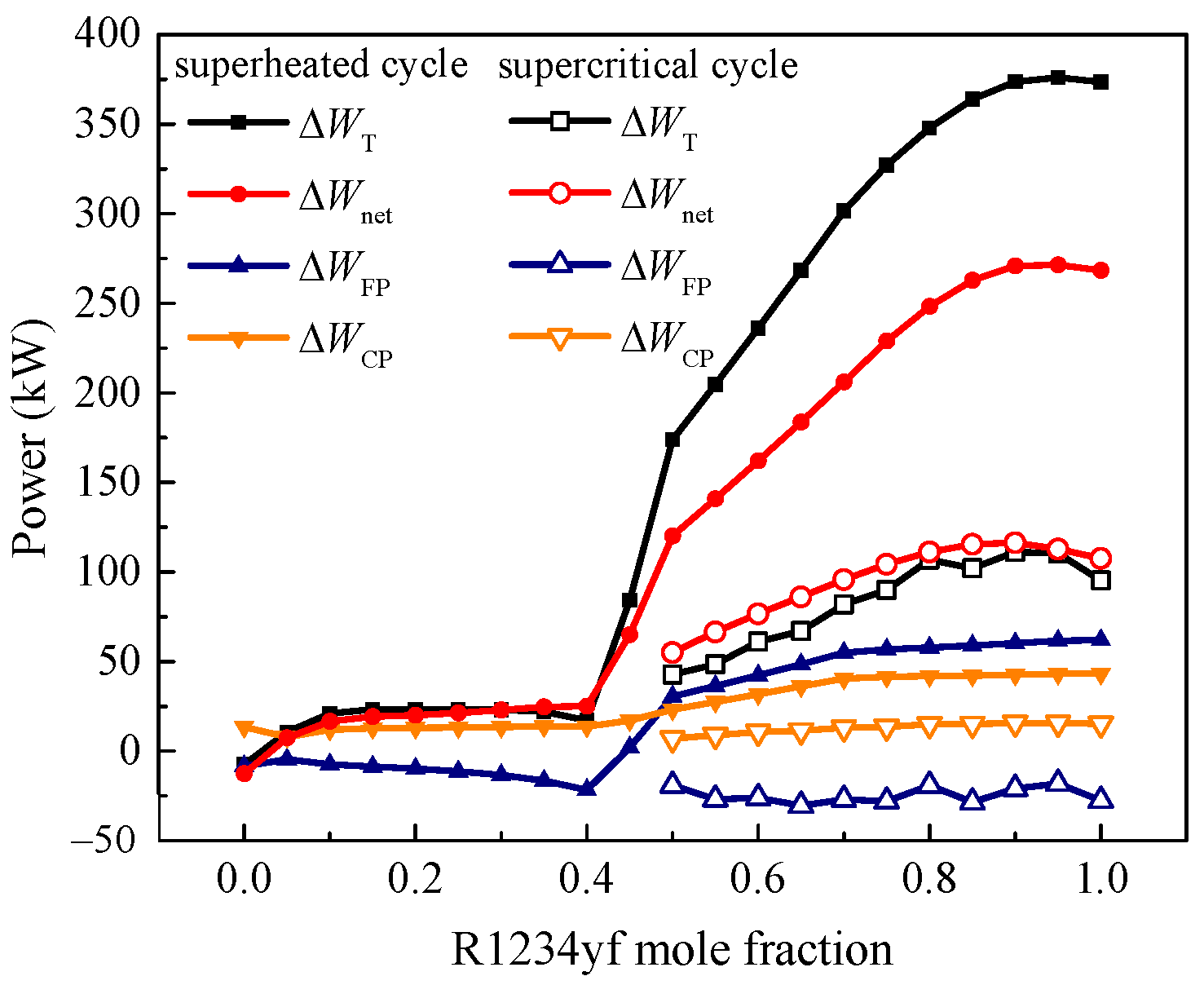
Figure 20 shows the changes in the turbine power, net power and the parasitic power consumed by the working fluid pump and the cooling water circulating pump affected by using an IHE for the brine temperature of 423.15 K. The optimal evaporation pressures for R1234yf mole fractions less than 0.4 were reduced when using an IHE for the superheated cycle, while the working fluid mass flow rates were increased by 5.2–8.9%. The power generated from the turbine only increased by 10.5–23.2 kW with an IHE. The power consumed by the working fluid pump in the superheated cycle with the IHE decreased by 4.7–21.7 kW, but the power consumed by the circulating pump increased by 7.9–13.8 kW for R1234yf mole fractions less than 0.4. Thus, the net power output increased by 7.3–25 kW (0.4–1.4%). The evaporation pressure remained at 0.8pc for R1234yf mole fractions higher than 0.5 for the superheated cycle with the IHE. However, the increase in the working fluid mass flow rate by the IHE increased from 15.8% for the R1234yf mole fraction of 0.5 to 36.4% for the R1234yf mole fraction of 0.95. The turbine power increased from 173.8 kW (8.2%) to 376 kW (20.7%) through the use of the IHE as the R1234yf mole fraction increased from 0.5 to 0.95. Both the power consumption of the working fluid pump and the circulating pump increased, and the net power increased from 120.1 kW (6.7%) to 271.3 kW (17.8%) as the R1234yf mole fraction increased from 0.5 to 0.95. The use of an IHE for the supercritical cycle increased the evaporator inlet temperature and decreased the optimal turbine inlet temperature, which resulted in a lower temperature rise in the evaporator; thus, the working fluid mass flow rate increased. The power consumed by the circulating pump increased by 7–15.7 kW for the supercritical cycle with the IHE, while the power consumed by the working fluid pump decreased by 19.2–30.4 kW. The net power increased by 55–116.3 kW (2.9–5.9%) due to the use of the IHE for the supercritical cycle.

3.5. Exergy Efficiency

Figure 21 shows the exergy efficiencies of subcritical and supercritical ORCs using R1234yf/R236ea for various geothermal brine temperatures. The exergy destruction mainly occurred in the evaporation, condensation, expansion and geothermal brine reinjection processes. The exergy destruction rates in reinjection were the same for a given heat source because of the same reinjection temperatures, except for the superheated cycle with an IHE for R1234yf mole fractions between 0.05 and 0.4, so these are not further discussed. The exergy efficiencies of the saturated cycle were slightly higher than those of the superheated cycle using mixtures with lower R1234yf mole fractions mainly because of the lower exergy destruction rates in the condenser and evaporator. However, the evaporation pressure of the saturated cycle was limited by the turning point for higher R1234yf mole fractions, resulting in excessive exergy destruction in the evaporator, particularly for higher source temperatures; thus, the exergy efficiency of the saturated cycle sharply decreased. Thus, the saturated ORC was more proper for working fluids with higher critical temperatures. The superheated cycle using R1234yf/R236ea (0.8/0.2) had the highest exergy efficiency of 25.63% for the brine temperature of 383.15 K. The use of an IHE for the superheated cycle reduced the exergy destruction rates in the condenser and evaporator. Thus, the exergy efficiencies of the superheated cycle with the IHE were higher than those of the superheated and saturated cycles for R1234yf mole fractions higher than 0.2. Two mole fractions maximized the exergy efficiency for the superheated cycle using the IHE, with the maximum exergy efficiency of 33.81% at the R1234yf mole fraction of 0.85 for the brine temperature of 403.15 K. The exergy efficiency of the superheated cycle with the IHE was slightly higher than that of the supercritical cycle for x R 1234 yf 0.6 because of the lower exergy destruction rates in the condenser and turbine for the brine temperature of 423.15 K. The exergy efficiency of the supercritical cycle with the IHE ranged from 39.57 to 42.36%, 2.9–5.9% relatively higher than that of the supercritical cycle due to reduction in the exergy destruction in the evaporator and condenser. The supercritical cycle with the IHE had the highest exergy efficiency using R1234yf/R236ea (0.85/0.15), which was 3.1% relatively higher than that using pure R1234yf.

4. Conclusions

This work studied the thermodynamic characteristics of saturated, superheated and supercritical ORCs using zeotropic mixtures of R1234yf/R236ea. The evaporation and condensation pressures were simultaneously optimized to maximize the net power output for various brine temperatures with reinjection temperatures of no less than 343.15 K. The results showed the following:
(1) The saturated ORC output slightly more net power than the superheated ORC using R1234yf/R236eaf with R1234yf mole fractions less than 0.2 due to the lower exergy destruction rates in the evaporator and condenser. The evaporation pressures of the R1234yf/R236ea mixtures were limited by the turning point for saturated cycles at higher R1234yf mole fractions, resulting in excessive exergy destruction in the evaporator and less net power output, especially for higher brine temperatures. The saturated cycle was more promising for working fluids with higher critical temperatures.
(2) Two local maxima appeared in the net power output and exergy efficiency for the superheated ORC, with maximum net power outputs at the R1234yf mole fraction of 0.8 for brine temperatures of 383.15 K and 403.15 K. For a higher brine temperature, the evaporation pressure and temperature of a superheated ORC may reach the upper limits with R1234yf/R236ea at a higher R1234yf mole fraction, resulting in larger temperature difference between the brine and the working fluid, which could cause excessive exergy losses. The use of an IHE could recover part of the sensible heat from the turbine exhaust and increase the preheater inlet temperature, resulting in better temperature matching between the brine and the working fluid and lower exergy destruction rates in the evaporator and condenser. The exergy efficiency of the superheated ORC with the IHE was slightly higher than that of the supercritical ORC for 0.5 x R 1234 yf 0.6 when the brine temperature was 423.15 K.
(3) Both the optimal evaporation pressure and turbine inlet temperature for the supercritical ORC increased with increasing R1234yf mole fraction for x R 1234 yf 0.5 . The better temperature matching between the brine and the working fluid led to a lower exergy destruction rate in the evaporator. The use of an IHE reduced the optimal turbine inlet temperature by 5.1–7.9 K, resulting in a 9.9–15.8% decrease in the exergy destruction rate in the evaporator, a 2.7–13% decrease in the exergy destruction rate in the condenser, and a 2.9–5.9% increase in the net power output. The supercritical cycle with the IHE had the highest exergy efficiency using R1234yf/R236ea (0.85/0.15) for the brine temperature of 423.15 K.

Author Contributions

Conceptualization, Q.L.; methodology, R.C. and Q.L.; software, R.C. and Q.L.; validation, Q.L., R.C. and X.Y.; formal analysis, Q.L. and R.C.; investigation, Q.L. and R.C.; resources, Q.L.; data curation, R.C. and X.X.; writing—original draft preparation, Q.L., R.C. and X.Y.; writing—review and editing, Q.L. and X.X.; visualization, Q.L., R.C. and X.Y.; supervision, Q.L.; project administration, Q.L.; funding acquisition, Q.L. All authors have read and agreed to the published version of the manuscript.

Funding

This research was funded by the National Natural Science Foundation of China by grant numbers 51736005 and 51506223.

Institutional Review Board Statement

Not applicable.

Informed Consent Statement

Not applicable.

Data Availability Statement

Not applicable.

Conflicts of Interest

The authors declare no conflict of interest.

References

  1. Jain, C.; Christian, V.; Clauser, C. Maximum potential for geothermal power in Germany based on engineered geothermal systems. Geotherm. Energy 2015, 3, 15. [Google Scholar] [CrossRef] [Green Version]
  2. Balat, M.; Balat, H.; Faiz, U. Utilization of Geothermal Energy for Sustainable Global Development. Energy Sources Part B Econ. Plan. Policy 2009, 4, 295–309. [Google Scholar] [CrossRef]
  3. Anderson, A.; Rezaie, B. Geothermal technology: Trends and potential role in a sustainable future. Appl. Energy 2019, 248, 18–34. [Google Scholar] [CrossRef]
  4. Dipippo, R. Second law assessment of binary plants generating power from low-temperature geothermal fluids. Geothermics 2004, 33, 565–586. [Google Scholar] [CrossRef] [Green Version]
  5. Hu, S.; Yang, Z.; Li, J.; Duan, Y. A Review of Multi-Objective Optimization in Organic Rankine Cycle (ORC) System Design. Energies 2021, 14, 6492. [Google Scholar] [CrossRef]
  6. Luo, X.L.; Wang, Y.P.; Liang, J.W.; Qi, J.; Su, W.; Yang, Z.; Chen, J.W.; Wang, C.; Chen, Y. Improved correlations for working fluid properties prediction and their application in performance evaluation of sub-critical Organic Rankine Cycle. Energy 2019, 174, 122–137. [Google Scholar] [CrossRef]
  7. Wang, S.K.; Liu, C.; Li, Q.B.; Liu, L.; Huo, E.G.; Zhang, C. Selection principle of working fluid for organic Rankine cycle based on environmental benefits and economic performance. Appl. Therm. Eng. 2020, 178, 115598. [Google Scholar] [CrossRef]
  8. Wang, Z.J.; Tian, H.; Shi, L.F.; Shu, G.Q.; Kong, X.H.; Li, L.G. Fluid Selection of Transcritical Rankine Cycle for Engine Waste Heat Recovery Based on Temperature Match Method. Energies 2020, 13, 1830. [Google Scholar] [CrossRef] [Green Version]
  9. Xu, W.C.; Deng, S.; Su, W.; Zhang, Y.; Zhao, L.; Yu, Z.X. How to approach Carnot cycle via zeotropic working fluid: Research methodology and case study. Energy 2018, 144, 576–586. [Google Scholar] [CrossRef]
  10. Heberle, F.; Brüeggemann, D. Thermo-Economic Analysis of Zeotropic Mixtures and Pure Working Fluids in Organic Rankine Cycles for Waste Heat Recovery. Energies 2016, 9, 226. [Google Scholar] [CrossRef] [Green Version]
  11. Heberle, F.; Brüeggemann, D. Thermo-Economic Evaluation of Organic Rankine Cycles for Geothermal Power Generation Using Zeotropic Mixtures. Energies 2015, 8, 2097–2124. [Google Scholar] [CrossRef] [Green Version]
  12. Lecompte, S.; Ameel, B.; Ziviani, D.; van den Broek, M.; De Paepe, M. Exergy analysis of zeotropic mixtures as working fluids in Organic Rankine Cycles. Energy Convers. Manag. 2014, 85, 727–739. [Google Scholar] [CrossRef]
  13. Liu, Q.; Shen, A.J.; Duan, Y.Y. Parametric optimization and performance analyses of geothermal organic Rankine cycles using R600a/R601a mixtures as working fluids. Appl. Energy 2015, 148, 410–420. [Google Scholar] [CrossRef]
  14. Liu, Q.; Duan, Y.Y.; Yang, Z. Effect of condensation temperature glide on the performance of organic Rankine cycles with zeotropic mixture working fluids. Appl. Energy 2014, 115, 394–404. [Google Scholar] [CrossRef]
  15. Chys, M.; Van Den Broek, M.; Vanslambrouck, B.; De Paepe, M. Potential of zeotropic mixtures as working fluids in organic Rankine cycles. Energy 2012, 44, 623–632. [Google Scholar] [CrossRef]
  16. Wang, S.; Zhang, W.; Feng, Y.Q.; Wang, X.; Wang, Q.; Liu, Y.Z.; Wang, Y.; Yao, L. Entropy, Entransy and Exergy Analysis of a Dual-Loop Organic Rankine Cycle (DORC) Using Mixture Working Fluids for Engine Waste Heat Recovery. Energies 2020, 13, 1301. [Google Scholar] [CrossRef] [Green Version]
  17. Feng, Y.Q.; Hung, T.C.; He, Y.L.; Wang, Q.; Wang, S.; Li, B.X.; Lin, J.R.; Zhang, W.P. Operation characteristic and performance comparison of organic Rankine cycle (ORC) for low-grade waste heat using R245fa, R123 and their mixtures. Energy Convers. Manag. 2017, 144, 153–163. [Google Scholar] [CrossRef]
  18. Chen, H.J.; Goswami, D.Y.; Stefanakos, E.K. A review of thermodynamic cycles and working fluids for the conversion of low-grade heat. Renew. Sust. Energ. Rev. 2010, 14, 3059–3067. [Google Scholar] [CrossRef]
  19. Xu, W.C.; Deng, S.; Zhao, L.; Su, W.; Zhang, Y.; Li, S.J.; Ma, M.L. How to quantitatively describe the role of the pure working fluids in subcritical organic Rankine cycle: A limitation on efficiency. Energy Convers. Manag. 2018, 172, 316–327. [Google Scholar] [CrossRef]
  20. Shi, L.F.; Shu, G.Q.; Tian, H.; Deng, S. A review of modified Organic Rankine cycles (ORCs) for internal combustion engine waste heat recovery (ICE-WHR). Renew. Sust. Energ. Rev. 2018, 92, 95–110. [Google Scholar] [CrossRef]
  21. Oyewunmi, O.A.; Kirmse, C.J.W.; Pantaleo, A.M.; Markides, C.N. Performance of working-fluid mixtures in ORC-CHP systems for different heat-demand segments and heat-recovery temperature levels. Energy Convers. Manag. 2017, 148, 1508–1524. [Google Scholar] [CrossRef]
  22. Quoilin, S.; Van den Broek, M.; Declaye, S.; Dewallef, P.; Lemort, V. Techno-economic survey of Organic Rankine Cycle (ORC) systems. Renew. Sust. Energ. Rev. 2013, 22, 168–186. [Google Scholar] [CrossRef] [Green Version]
  23. Miao, Z.; Zhang, K.; Wang, M.X.; Xu, J.L. Thermodynamic selection criteria of zeotropic mixtures for subcritical organic Rankine cycle. Energy 2019, 167, 484–497. [Google Scholar] [CrossRef]
  24. Yang, F.F.; Yang, F.B.; Chu, Q.F.; Liu, Q.; Yang, Z.; Duan, Y.Y. Thermodynamic performance limits of the organic Rankine cycle: Working fluid parameterization based on corresponding states modeling. Energy Convers. Manag. 2020, 217, 113011. [Google Scholar] [CrossRef]
  25. Braimakis, K.; Mikelis, A.; Charalampidis, A.; Charalampidis, A.; Karellas, S. Exergetic performance of CO2 and ultra-low GWP refrigerant mixtures as working fluids in ORC for waste heat recovery. Energy 2020, 203, 117801. [Google Scholar] [CrossRef]
  26. Dong, B.S.; Xu, G.Q.; Li, T.T.; Quan, Y.K.; Wen, J. Thermodynamic and economic analysis of zeotropic mixtures as working fluids in low temperature organic Rankine cycles. Appl. Therm. Eng. 2018, 132, 545–553. [Google Scholar] [CrossRef]
  27. Su, W.; Hwang, Y.H.; Deng, S.; Zhao, L.; Zhao, D.P. Thermodynamic performance comparison of Organic Rankine Cycle between zeotropic mixtures and pure fluids under open heat source. Energy Convers. Manag. 2018, 165, 720–737. [Google Scholar] [CrossRef]
  28. Xi, H.; Li, M.J.; He, Y.L.; Zhang, Y.W. Economical evaluation and optimization of organic Rankine cycle with mixture working fluids using R245fa as flame retardant. Appl. Therm. Eng. 2017, 113, 1056–1070. [Google Scholar] [CrossRef]
  29. Feng, Y.Q.; Luo, Q.H.; Wang, Q.; Wang, S.; He, Z.X.; Zhang, W.; Wang, X.; An, Q.S. Entropy and Entransy Dissipation Analysis of a Basic Organic Rankine Cycles (ORCs) to Recover Low-Grade Waste Heat Using Mixture Working Fluids. Entropy 2018, 20, 818. [Google Scholar] [CrossRef] [PubMed]
  30. Feng, Y.Q.; Hung, T.C.; Greg, K.; Zhang, Y.N.; Li, B.X.; Yang, J.F. Thermoeconomic comparison between pure and mixture working fluids of organic Rankine cycles (ORCs) for low temperature waste heat recovery. Energy Convers. Manag. 2015, 106, 859–872. [Google Scholar] [CrossRef]
  31. Zhai, H.X.; An, Q.S.; Shi, L. Zeotropic mixture active design method for organic Rankine cycle. Appl. Therm. Eng. 2018, 129, 1171–1180. [Google Scholar] [CrossRef]
  32. Lecompte, S.; Huisseune, H.; Van Den Broek, M.; Vanslambrouck, B.; De Paepe, M. Review of organic Rankine cycle (ORC) architectures for waste heat recovery. Renew. Sust. Energ. Rev. 2015, 47, 448–461. [Google Scholar] [CrossRef]
  33. Chen, H.J.; Goswami, D.Y.; Rahman, M.M.; Stefanakos, E.K. A supercritical Rankine cycle using zeotropic mixture working fluids for the conversion of low-grade heat into power. Energy 2011, 36, 549–555. [Google Scholar] [CrossRef]
  34. Zhang, X.X.; Zhang, Y.; Cao, M.; Wang, J.F.; Wu, Y.T.; Ma, C.F. Working Fluid Selection for Organic Rankine Cycle Using Single-Screw Expander. Energies 2019, 12, 3197. [Google Scholar] [CrossRef] [Green Version]
  35. Zhang, X.X.; Zhang, Y.; Li, Z.L.; Wang, J.F.; Wu, Y.T.; Ma, C.F. Zeotropic Mixture Selection for an Organic Rankine Cycle Using a Single Screw Expander. Energies 2020, 13, 1022. [Google Scholar] [CrossRef] [Green Version]
  36. Wang, X.C.; Levy, E.K.; Pan, C.J.; Romero, C.E.; Banerjee, A.; Rubio-Maya, C.; Pan, L.H. Working fluid selection for organic Rankine cycle power generation using hot produced supercritical CO2 from a geothermal reservoir. Appl. Therm. Eng. 2019, 149, 1287–1304. [Google Scholar] [CrossRef]
  37. Meng, N.; Li, T.L.; Jia, Y.A.; Qin, H.S.; Liu, Q.H.; Zhao, W.Q.; Lei, G.B. Techno-economic performance comparison of enhanced geothermal system with typical cycle configurations for combined heating and power. Energy Convers. Manag. 2020, 205, 112409. [Google Scholar] [CrossRef]
  38. Zhang, C.; Liu, C.; Xu, X.X.; Li, Q.B.; Wang, S.K.; Chen, X. Effects of superheat and internal heat exchanger on thermo-economic performance of organic Rankine cycle based on fluid type and heat sources. Energy 2018, 159, 482–495. [Google Scholar] [CrossRef]
  39. Saleh, B.; Koglbauer, G.; Wendland, M.; Fischer, J. Working fluids for low-temperature organic Rankine cycles. Energy 2007, 32, 1210–1221. [Google Scholar] [CrossRef]
  40. Li, S.; Dai, Y.P. Thermo-Economic Analysis of Waste Heat Recovery ORC Using Zeotropic Mixtures. J. Energy Eng. 2015, 141, 4014050. [Google Scholar] [CrossRef]
  41. Fang, Y.W.; Yang, F.B.; Zhang, H.G. Comparative analysis and multi-objective optimization of organic Rankine cycle (ORC) using pure working fluids and their zeotropic mixtures for diesel engine waste heat recovery. Appl. Therm. Eng. 2019, 157, 113704. [Google Scholar] [CrossRef]
  42. Li, C.Y.; Wang, H.X. Power cycles for waste heat recovery from medium to high temperature flue gas sources—From a view of thermodynamic optimization. Appl. Energy 2016, 180, 707–721. [Google Scholar] [CrossRef]
  43. Song, C.Z.; Gu, M.Y.; Miao, Z.; Liu, C.; Xu, J.L. Effect of fluid dryness and critical temperature on trans-critical organic Rankine cycle. Energy 2019, 174, 97–109. [Google Scholar] [CrossRef]
  44. Invernizzi, C.M.; Ayub, A.; Di Marcoberardino, G.; Lora, P. Pure and Hydrocarbon Binary Mixtures as Possible Alternatives Working Fluids to the Usual Organic Rankine Cycles Biomass Conversion Systems. Energies 2019, 12, 4140. [Google Scholar] [CrossRef] [Green Version]
  45. Zhang, C.; Fu, J.L.; Yuan, P.F.; Liu, J.J. Guidelines for Optimal Selection of Subcritical Low-Temperature Geothermal Organic Rankine Cycle Configuration Considering Reinjection Temperature Limits. Energies 2018, 11, 2878. [Google Scholar] [CrossRef] [Green Version]
  46. Chen, Q.C.; Xu, J.L.; Chen, H.X. A new design method for Organic Rankine Cycles with constraint of inlet and outlet heat carrier fluid temperatures coupling with the heat source. Appl. Energy 2012, 98, 562–573. [Google Scholar] [CrossRef]
  47. Oyewunmi, O.A.; Ferre-Serres, S.; Lecompte, S.; van den Broek, M.; de Paepe, M.; Markides, C.N. An assessment of subcritical and trans-critical organic Rankine cycles for waste-heat recovery. Energy Procedia 2017, 105, 1870–1876. [Google Scholar] [CrossRef]
  48. Invernizzi, C.; Bombarda, P. Thermodynamic performance of selected HCFS for geothermal applications. Energy 1997, 22, 887–895. [Google Scholar] [CrossRef]
  49. Feng, Y.Q.; Hung, T.C.; Wu, S.L.; Lin, C.H.; Li, B.X.; Huang, K.C.; Qin, J. Operation characteristic of a R123-based organic Rankine cycle depending on working fluid mass flow rates and heat source temperatures. Energy Convers. Manag. 2017, 131, 55–68. [Google Scholar] [CrossRef]
  50. Heberle, F.; Preißinger, M.; Brüeggemann, D. Zeotropic mixtures as working fluids in Organic Rankine Cycles for low-enthalpy geothermal resources. Renew. Energy 2012, 37, 364–370. [Google Scholar] [CrossRef]
  51. Pan, L.S.; Shi, W.X. Investigation on the Pinch Point Position in Heat Exchangers. J. Therm. Sci. 2016, 25, 258–265. [Google Scholar] [CrossRef] [Green Version]
  52. Sun, J.; Liu, Q.; Duan, Y.Y. Effects of evaporator pinch point temperature difference on thermo-economic performance of geothermal organic Rankine cycle systems. Geothermics 2018, 75, 249–258. [Google Scholar] [CrossRef]
  53. Meng, D.Y.; Liu, Q.; Ji, Z.L. Performance analyses of regenerative organic flash cycles for geothermal power generation. Energy Convers. Manag. 2020, 224, 113396. [Google Scholar] [CrossRef]
Figure 1. Schematics of (a) a basic ORC and (b) an ORC with an IHE.
Energies 16 05676 g001
Figure 2. T–s diagram with the turning point.
Energies 16 05676 g002
Figure 3. (a) Pressures and (b) temperatures of the critical and turning points of R1234yf/R236ea for various mole fractions from REFPROP 9.1.
Energies 16 05676 g003
Figure 4. T-s diagrams for (a) saturated ORC; (b) superheated ORC; and (c) supercritical ORC.
Energies 16 05676 g004
Figure 5. Pinch-point determination of the evaporation process.
Energies 16 05676 g005
Figure 6. Schematic of typical pinch-point location during condensation for zeotropic mixtures.
Energies 16 05676 g006
Figure 7. Flow chart for parameter optimization.
Energies 16 05676 g007
Figure 8. Condensation pressures of R1234yf/R236ea for various mole fractions.
Energies 16 05676 g008
Figure 9. Optimal reduced evaporation pressures of saturated, superheated and supercritical cycles for brine temperatures of (a) 383.15 K, (b) 403.15 K and (c) 423.15 K.
Energies 16 05676 g009
Figure 10. T–Q diagrams for (a) ORCs using R1234yf/R236ea (0.2/0.8) and (b) ORCs using R1234yf/R236ea (0.7/0.3).
Energies 16 05676 g010
Figure 11. Turbine inlet temperatures of saturated, superheated and supercritical cycles for various R1234yf mole fractions and brine temperatures of (a) 383.15 K, (b) 403.15 K and (c) 423.15 K.
Energies 16 05676 g011
Figure 12. Net power outputs of various cycle layouts for geothermal brine temperatures of (a) 383.15 K, (b) 403.15 K and (c) 423.15 K.
Energies 16 05676 g012
Figure 13. Exergy destruction during evaporation for brine temperatures of (a) 383.15 K; (b) 403.15 K; and (c) 423.15 K.
Energies 16 05676 g013
Figure 14. Exergy destruction during condensation for brine temperatures of (a) 383.15 K; (b) 403.15 K; and (c) 423.15 K.
Energies 16 05676 g014
Figure 15. Exergy destruction rates of the components and exergy efficiencies of the cycles: (a) R1234yf/R236ea (0.1/0.9) and (b) R1234yf/R236ea (0.8/0.2).
Energies 16 05676 g015
Figure 16. Working fluid temperature rise in heaters: (a) superheated cycle and (b) supercritical cycle with and without an IHE.
Energies 16 05676 g016
Figure 17. Heat flow distribution in the preheater, evaporator and superheater of superheated cycles with and without an IHE.
Energies 16 05676 g017
Figure 18. Exergy destruction for evaporation: (a) superheated cycle and (b) supercritical cycle with and without an IHE for the brine temperature of 423.15 K.
Energies 16 05676 g018
Figure 19. Exergy destruction for condensation: (a) superheated cycle and (b) supercritical cycle with and without an IHE for the brine temperature of 423.15 K.
Energies 16 05676 g019
Figure 20. Variation in turbine power, net power and power consumption of working fluid pump and circulating pump with an IHE for the brine temperature of 423.15 K.
Energies 16 05676 g020
Figure 21. Exergy efficiencies of ORCs using R1234yf/R236ea for various brine temperatures.
Energies 16 05676 g021
Table 1. Boundary conditions and operating parameters of the geothermal ORC.
ParameterValue
Geothermal brine temperature (K)423.15, 403.15, 383.15
Geothermal brine reinjection temperature (K)≥343.15
Geothermal water pressure (kPa)4000
Geothermal water mass flow (kg/s)50
Evaporator pinch-point temperature difference (K)10
Condenser pinch-point temperature difference (K)5
IHE pinch-point temperature difference (K)10
Cooling water inlet temperature (K)293.15
Circulating pump head (m)20
Circulating pump efficiency0.8
Turbine efficiency0.85
Pump isentropic efficiency0.75
Turbine mechanical efficiency0.98
Generating efficiency0.98
Disclaimer/Publisher’s Note: The statements, opinions and data contained in all publications are solely those of the individual author(s) and contributor(s) and not of MDPI and/or the editor(s). MDPI and/or the editor(s) disclaim responsibility for any injury to people or property resulting from any ideas, methods, instructions or products referred to in the content.