Review

A Comprehensive Review of Flexible Power-Point-Tracking Algorithms for Grid-Connected Photovoltaic Systems

1
Department of Electrical & Electronics Engineering, School of Engineering, University of Petroleum and Energy Studies, Dehradun 248007, India
2
Department of Electrical and Electronics Engineering, SRM Institute of Science and Technology, Delhi-NCR Campus, Ghaziabad 201204, India
3
MCAST Energy Research Group, Institute of Engineering and Transport, Malta College of Arts, Science and Technology (MCAST), Main Campus, Corradino Hill, PLA 9032 Paola, Malta
4
The Foundation for Innovation and Research—Malta, 65 Design Centre Level 2, Tower Road, BKR 4012 Birkirkara, Malta
*
Authors to whom correspondence should be addressed.
Energies 2023, 16(15), 5679; https://doi.org/10.3390/en16155679
Submission received: 7 June 2023 / Revised: 26 June 2023 / Accepted: 19 July 2023 / Published: 28 July 2023
(This article belongs to the Section A2: Solar Energy and Photovoltaic Systems)

Abstract

:
The rapid increase in the penetration of photovoltaic (PV) power plants results in an increased risk of grid failure, primarily due to the intermittent nature of the plant. To overcome this problem, the flexible power point tracking (FPPT) algorithm has been proposed in the literature over the maximum power point tracking (MPPT) algorithm. These algorithms regulate the PV power to a certain value instead of continuously monitoring the maximum power point (MPP). The proposed work carries out a detailed comparative study of various constant power generation (CPG) control strategies. The control strategies are categorized in terms of current-, voltage-, and power-based tracking capabilities. The comparative analysis of various reported CPG/FPPT techniques was carried out. This analysis was based on some key performance indices, such as the type of control strategy, irradiance pattern, variation in G, region of operation, speed of tracking, steady-state power oscillations, drift severity scenario, partial shading scenario, implementation complexity, stability, fast dynamic response, robustness, reactive power, cost, and tracking efficiency. Among existing FPPT algorithms, model-based control has a superior performance in terms of tracking speed and low steady-state power oscillations, with a maximum tracking efficiency of 98.57%.

1. Introduction

PV cells are the basic unit of PV systems that directly converts incident sun radiation into electrical energy through the photovoltaic effect [1]. To increase power generation, a number of solar cells are connected in series or in parallel to make up the solar panel or module [2]. Further, a number of modules or panels are mounted together to form solar farms or solar power plants. Solar plants are used to generate electricity on a large scale so as to meet increased energy demands. PV power plants are generally operated in two configurations, i.e., standalone and grid-connected PV systems [2,3,4].
Under normal operating conditions, grid-connected PV (GCPV) systems are operated at maximum power point, using MPPT algorithms (such as perturb and observe (P&O), incremental conductance (INC), and incremental resistance (INR)) to extract the maximum power [5,6,7]. During recent years, increased PV grid penetrations are creating major challenges for system operators [8,9,10]. Since PV systems are intermittent in nature, the system operators are facing difficulty in ensuring the stability of the power system. In order to stabilize the voltage and frequency of the PV output power, various grid codes have been formulated that specify the operating limits of the GCPV system [11,12,13,14,15,16,17,18,19,20]. According to the grid codes, the output from PV needs to be controlled to provide ancillary services under fault-ride-through/frequency-ride-through conditions [21,22].
During fault-ride-through/frequency-ride-through conditions, active power from the PV system is curtailed using a suitable constant power generation technique to provide adequate leeway for ancillary services [23,24,25]. This constant power generation technique is usually referred to as a flexible power-point-tracking (FPPT) algorithm, which is used to extract reduced constant power from the PV system by operating away from the MPP for a short duration under varying environmental conditions [26,27]. As soon as the fault is cleared, the FPPT algorithm starts tracking the MPP and behaves like the MPPT algorithm, hence the name flexible power point tracking, as it flexibly tracks both constant power and maximum power operating points on the PV power curve based on the operating conditions [28,29,30,31,32,33,34,35].
In recent years, several researchers have proposed FPPT control strategies by carefully modifying hill-climbing algorithms to improve the speed of convergence while reducing the steady-state power oscillations to track the CPP of the PV system. In [36], the authors addressed the fault-ride-through situation for single- and two-stage grid-tied PV systems. In this work, a DC-link energy-based FPPT controller was proposed to address the above-mentioned situation and to validate the same situation under standard test conditions (STC). However, its performance was not analyzed under rapidly changing irradiance. In [37], the authors proposed an FPPT algorithm by deploying an advanced P&O-based power control strategy to ensure a fast and smooth transition between MPP and CPG. The proposed method is also compatible with single-stage PV systems, but the PV voltage operating range is rather limited; thus, some changes will be needed for the algorithm’s stable operation. In [38], the authors proposed a fixed-voltage-step-based FPPT control, in which FPP is tracked using constant voltage step-size under STC. The algorithm was tested for different irradiance conditions at the time of reduced power mode and showed fast performance. Due to its fast performance, the proposed algorithm can be further utilized in multistring grid-connected PV systems during voltage-ride-through period. In [39], the authors carried out a detailed investigation for the constant power generation method for power reserves. The work proposed a cost-effective method for constant power generation under STC to ensure the availability of power reserves during the frequency-ride-through period. However, the proposed method needs to be tested under rapidly changing irradiance conditions. In [40], the authors proposed a dual-perturbation time-step-based FPPT control. Detailed investigations were carried out on two perturbation time steps for both MPPT and FPPT control algorithms. The proposed algorithm is flexible in tracking the point of operation on the left or right side of MPP. The algorithm can be utilized in both single-stage and two-stage photovoltaic power plant (PVPP) strategies. In [41], the authors proposed a delta power control (DPC) method to increase the stability of grid-connected PV systems. In this work, the PV power is regulated on the left trail of the PV curve, which makes it more efficient, but due to the complexity of the scheme, it is not cost-effective. In [42], the authors performed experimental analysis by making use of dual-step-size-based FPPT control. The proposed method used two distinct step-sizes for efficient tracking during the transient and steady states. However, CPG performance can be enhanced by making use of adaptive voltage step-size calculations. In [43], the authors developed three CPG techniques using the P&O algorithm. These three methods are based on power control (P-CPG) and a current-limiting method (I-CPG) and are validated on a two-stage grid-connected photovoltaic (GCPV) experimental test bench. These algorithms are compared on the basis of parameters like steady-state performance, tracking error, stability, and complexity. It has been realized that I-CPG is simple in structure, but it is prone to instability, and P-CPG shows good steady-state response. However, in CPG-P&O algorithms, the tracking error increases with rapid changes in irradiance. In [44], the authors developed an adaptive step-size-based FPPT control, in which the step-size was adaptively varied to track both the MPP and FPP of PV systems. But, the proposed algorithm is complex in nature. In [45], the authors investigated a dynamic-voltage-reference- and MPC-based FPPT control to address frequency and voltage-ride-through issues that occur in grid-connected PV systems. The method works on dynamic-voltage reference designs. The performance of the algorithm is estimated in terms of transient response under voltage sags and frequency deviation. In [46], the authors proposed a modified power-based FPPT algorithm, which has the ability to track the CPP on both left and right side of MPP, i.e., multi-mode operation. The algorithm has the capability to quickly track the CPP, but it may not be applicable in the case of rapid changes in irradiance. In [47], the authors proposed a DC-link voltage-based FPPT control, where the FPP was tracked using a model-predictive controller and was tested on the battery load. The main focus has been to regulate the battery by considering its lifetime, but the algorithm has not been explored much. In [48], the authors introduced a binary search-based FPPT control, which mainly improves the speed of convergence by iteratively reducing the search space to half of its previous value. But, the algorithm is not tested under rapid changes in irradiance or temperature. In [49], the authors introduced a secant-method-based FPPT control, which tracks the FPP irrespective of an increasing or decreasing power reference value under STC. The method is fast, and it shows low steady-state oscillations, but it becomes unstable under changing environmental conditions. In [50], the authors proposed an error-based active disturbance rejection FPPT control algorithm for constant power generation from PV systems. The method is efficient when compared to the conventional P&O method, but it is missing a rapid parameter tuning. In [51], the authors proposed a hill-climbing-method-based FPPT control under partial shading conditions. But, the method is not able to reduce steady-state oscillations. In [52], the authors proposed a fuzzy logic control and least mean square (LMS) control for CPG under varying irradiance and constant temperature conditions. But the method is complex, which makes it costly to apply in practice. In [53], the authors proposed a GFPPT control under partial shading conditions. The main purpose is to attain the CPP faster in case of rapid changes in irradiance, but the results are not satisfactory. In [54], the authors proposed a virtual synchronous generator (VSG)-control-strategy-based FPPT algorithm. It was claimed that it can be used to maintain the stability of the grid at the time of intermittency, but it has not been tested yet. In [55], the authors proposed a DC-link model based MPPT/FPPT control, which has the capability to operate under changing irradiance. The researchers also developed a finite-set model predictive control (FS-MPC) algorithm to appropriately manage active and reactive power exchange in grid-connected PV systems. But parameters like steady-state oscillations, speed of convergence and tracking efficiency are not satisfactory. A comprehensive literature survey of the various FPPT algorithms is shown in Table 1.
During recent years, several review articles have shined a light on FPPT algorithms for GCPV systems [56,57,58]. However, none of the articles have provided a detailed classification or have critically reviewed the recently developed FPPT algorithms of PV systems based on various key performance indicators, such as type of control strategy, variation in irradiance, region of operation, speed of tracking, steady-state oscillations, drift severity scenario, partial shading scenario, stability, fast dynamic response, robustness, implementation complexity, cost and tracking efficiency. This paper highlights the differences among the recently published review articles in Table 2 to show the existing research gap clearly. The proposed work also provides the readers with an exhaustive review of the various FPPT control strategies proposed to date under frequency/fault-ride-through conditions and provide avenues for future work. The key novelty features of the manuscript are:
  • The work discusses various challenges associated with tracking the FPP under varying environmental conditions.
  • The manuscript provides a detailed classification of the existing FPPT algorithms based on the control parameter used for tracking the CPP.
  • The work also carried out a critical review of the various FPPT control strategies highlighting their advantages and potential shortcomings. It also provides potential future scope of work.
The rest of the manuscript is organized as follows: Section 2 discusses the various challenges associated with FPPT algorithms. Section 3 carefully categorizes the existing FPPT/CPG techniques and carries out a detailed discussion on each technique. Section 4 provides a comparative analysis of the various FPPT algorithms based on some key performance indices. Finally, Section 5 provides the conclusion and a discussion on the future aspects of the FPPT control strategies.

2. Challenges

This section discusses the challenges associated with FPPT algorithm to track the CPP under rapidly changing irradiance conditions. The MPPT is known to have a limitation due to the intermittent nature of solar energy generated and the algorithm’s lack of flexibility in offering grid support, causing the need to move towards FPPT. Under normal operating conditions, the PV systems always operate on MPPT but in the case of the occurrence of a disturbance in the grid or under changing irradiance conditions, there is a need to operate using FPPT algorithm. The intermittency occurrence in sun radiations has a great impact on MPPT, so at that time, the point of operation should be shifted to FPPT either on the left trail or right trail of the P-V curve, as illustrated in Figure 1 [21,27]. There can be two cases, either the power can increase or decrease as depicted in Figure 2, respectively [49]. In both the cases, it is required to shift the point of operation from the MPP to the CPP; this process is called active power curtailment. The main purpose is the full convergence of the P-V curve to achieve the power reference. This process is achieved by using the secant method. First of all, P (power reference) and the operation side are attained, and then the initial values of parameters are fixed for the initial operation. The initial points are denoted by V 1 0 ,   P 1 0 and V 2 0 ,   P 2 0 , respectively. The voltage reference,   V (voltage reference), for the PV panel is evaluated as the intersection point of the P line and the common line crossing the above mentioned two points. To derive the equation for V , the secant method is utilized, as depicted in Equation (1) [49]:
V = V 1 k + ( V 2 k V 1 k )   ( P P 1 k )     ( P 2 k P 1 k )
where, k = 0, 1, 2, 3,… and so on.
The PV voltage   V P V is achieved by tracking   V . To track V , in the last repetition, V 2 k replaces V P V , and P 2 k replaces P P V . Then in the next step, the point ( V 2 0 , P 2 0 ) is replaced by ( V 2 1 , P 2 1 ), and the process continues. The same tracking process is followed for the operation on both the left and right trail of the P-V curve, but it differs in the initial search range. The error is calculated again for every repetition, and it is calculated by using Equation (2) [49]:
e k = P P P V .
where e k is the error in each step, and P P V is the power of the PV panel.
It can be concluded that the conditions in Equations (3) and (4) need to be satisfied for the solution to converge [49]:
| e k 1 | > | e k |
and   S i g n e k 1 = S i g n e k
This method will only converge to a specified range of the reference curve settings and not for power reference values. If a different operating curve will be used for different sets of conditions, then the method probably will not converge when   P m r e f < P < P m a c t . When the value of P m a c t is greater than   P m r e f , the controller will consider the value of P m r e f   as the most possible output power for the current environmental circumstances.
To overcome the above challenges, moving towards FPPT is the best possible solution. FPPT (flexible power point tracking) is introduced in the case of the occurrence of intermittency in generated PV power. At intermittency, MPPT offers no flexibility to provide grid support, during which there is a need for FPPT. Every time, it is not necessary to always operate on MPPT. Sometimes, due to a disturbance in the grid, there is a need to inject constant power into grid, this concept is called FPPT. However, in the literature, various algorithms are reported to detect FPPT under various intermittency conditions, but still there is the need to explore FPPT under rapidly changing irradiance and under partial shading conditions.
Some challenges associated with FPPT algorithms are:
  • The main one is to track the CPP at time of intermittency occurrence in grid. The intermittency is commonly called ride-through faults. Ride-through faults can be either voltage sags or frequency deviations. So, the algorithm should be designed to address such types of faults occurring in grid [40,58].
  • However, the multi-mode tracking of CPP is another major issue in FPPT algorithms. Some algorithms are not able to decide the mode of tracking or region of operation (i.e., either left or right trail of the P-V curve) for CPP tracking [46,53,59].
  • Furthermore, while designing an algorithm to track the CPP, some parameters, like speed of convergence, tracking efficiency and steady-state oscillations, should be considered for the betterment of performance. Additionally, implementation complexity and cost are also important aspects to keep in mind while designing an algorithm [56,57,58,59].
  • The aim of FPPT algorithms is to provide grid support at the time of faults in the grid. But FPPT algorithms experience difficulty in maintaining stability in grid at the time of partial shading scenarios [60,61,62,63,64,65].

3. Algorithm Discussion

This section consists of a brief discussion of the various algorithms reported in the literature until now. The algorithms are mainly focused on the regulation of PV power to a particular value to provide grid support. The authors have categorized the reported algorithms on the basis of three methods, namely voltage, current and power control approaches. All three categories are explained in following three subsections.

3.1. Voltage-Based FPPT/CPG Control

In this subsection, voltage control-based FPPT/CPG methods are explained in detail. In this technique, the point of operation is traced by utilizing the obtained PV voltage. The various voltage control-based techniques are:

3.1.1. DPTS (Dual Perturbation Time-Step-Based Algorithm) [40]

Dual perturbation time-step-based algorithm (DPTS) uses voltage as a control parameter to track the maximum and constant power point. The process flow of the proposed algorithm is depicted in Figure 3. The proposed algorithm has a dual mode of operation, which is controlled by an external signal. If the mode of operation is to track the MPP, the controller evaluates V r e f = V m p p using a conventional P&O MPPT algorithm. On the other hand, under CPG mode, the algorithm calculates V r e f . For this, three variables, V, P, and P , will be calculated, where P is defined as P = P n e w P r e f . At the initial stage, when the algorithm is working in MPPT mode, the voltage calculation time step ( T s t e p ) is intended to be comparatively large (e.g.,   T s t e p m p p t = 0.2 s ) in order to lessen output power fluctuations for the duration of the steady-state operation. However, the voltage step ( V s t e p ) between various operating points has to be relatively small ( V s t e p m p p t ) so as to decrease the power oscillation during MPPT. Further, for CPG operation, it is necessary to regulate the extracted power of the PV string ( P P V ) to a specified reference power ( P r e f ). As a result, a hysteresis band controller is utilized to evaluate T s t e p and V s t e p . The voltage reference is calculated by carefully evaluating the voltage perturbation step ( V s t e p ) and time perturbation ( T s t e p ). The voltage reference can be on any trail, either on left or right side of P-V curve.

3.1.2. DSSA (Dual Step-Size-Based Algorithm) [42]

Dual step-size-based algorithm (DSSA) is another voltage control method. The main focus is on the voltage calculation and reducing the power losses and steady-state oscillations. So, variable step-voltage ( V s t e p ) values are applied to achieve the reduced power losses and low steady-state oscillations. Figure 4 shows the schematic diagram of the proposed DSSA. The initial step is to select the operation mode, which can be either MPPT or CPG/RP, where RP is reduced power. On the basis of operating requirements, the operating mode of the PV system can be selected as either MPPT or CPG.
If the operating mode is MPPT, a nominal voltage-step is applied, while if the operating mode is under CPG operation, then different voltage-step values should to be used at the time of transient and steady-state operation as this will enhance the control performance. So, it is necessary to identify the initial operation conditions. This can be achieved by taking into consideration the alteration in the power reference. To differentiate between the two operating conditions, an operation boundary ( P t h ) is set, as shown in Equation (5) [42]:
P   P s h   S t e a d y s t a t e P > P t h r   T r a n s i e n t  
V = V n e w + V o l d
P = P n e w + P o l d
P = P n e w P r e f
As shown in Figure 4, the controller makes it simple to achieve this determination. However, using an easy comparison may contribute to the selection of inaccurate operating conditions while the PV system is at its peak power (MPP). There are two scenarios in which this can occur: Instead of functioning under CPG, the controller is configured to draw the most electricity possible from the PV system. The controller, in this instance, adjusts the power reference to a value greater than the nominal maximum power coming from the PV panel. At the time of utilizing CPG operation mode, the utmost achieved PV power ( P M P P ) is lesser than the reference power because of the intermittent solar radiation and other factors. The above-mentioned conditions will be distinguished by evaluating the slope of the P-V curve, which is calculated as Δ P Δ V . So, Δ P Δ V is close to zero when it is near to the MPP. Hence, to find the current operating point, this value is compared to a threshold ( T h r ). As the PV panel’s present operating point is not near the MPP and is more than T h r , a large voltage-step ( V s t e p c p g t r ) is chosen to quickly converge towards the FPP.
P > P s h
P V > T h
P = 0

3.1.3. V-P&O-A (Voltage Based P&O Algorithm) [43]

The voltage-based P&O algorithm (V-P&O-A) performs under CPG operation by using a P&O approach. This control strategy is based on the MPPT/CPG control structure, in which the PV voltage V P V is controlled to achieve the desired power. The schematic view of the control structure is illustrated in Figure 5. The proposed algorithm will change the control when the PV voltage reference ( V p v ) is calculated. When the mode of operation is set as CPG mode, the PV voltage ( V P V ) is persistently agitated in the direction of the CPP, which is given by P P V = P l i m i t . After a number of repetitions, the operating point will be achieved and fluctuate around the CPP. On the basis of the direction of perturbation, the algorithm can operate either on the left trail or the right trail of the CPP. However, due to the high slope of the P-V curve on the right side of the MPP (i.e., higher d P P V d V P V ), the power oscillations in the steady state at the CPP-R are greater than those at the CPP-L. This high-power oscillation should be avoided because it will reduce tracking precision and enlarge energy losses and power variations in the steady state.
The working region at the CPP-L, on the other hand, necessitates a larger conversion ratio (i.e., V d c V P V ), which may have an impact on the boost converter’s efficiency. The control structure of the algorithm depicts the reference PV voltage V p v , as illustrated in Equations (12) and (13) [43],
V p v = V M P P T ,   w h e n   P P V P l i m i t V P V V s t e p , w h e n   P P V > P l i m i t
if the point of operation is on the left trail of the CPP, or
V p v = V M P P T ,   w h e n   P P V P l i m i t V P V + V s t e p , w h e n   P P V > P l i m i t
Otherwise, if the point of operation is on the right trail of CPP, then V M P P T is the reference voltage from the MPPT algorithm, and V s t e p is the iteration step-size.

3.1.4. ASSA (Adaptive Step-Size-Based Algorithm) [44]

The adaptive step-size algorithm (ASSA) is based on the iteration of the reference voltage ( V r e f ) by voltage step-size V s t e p that adjusts as needed. The computational time step T s t e p is chosen in support of the optimal MPPT operation of PV system. The flowchart the algorithm is depicted in Figure 6. In this algorithm, first the V P V   a n d   I P V are measured, and the V P V   a n d   I P V values are recorded. Further, calculations are performed to evaluate the values of d V   a n d   d P . On the basis of these values, a voltage-reference calculation, either a voltage-step calculation or operation mode evaluation, is completed. To perform a voltage-reference calculation, the differential of the power reference should be greater than zero i.e., d P > 0 . If this condition is true, then the algorithm will check the operation region. If the operation region is on the left side of P-V curve, then the reference voltage will decrease by step-voltage, V r e f = V r e f o l d V s t e p ;   otherwise, the operation region will be on the right side of P-V curve, and reference voltage will increase by step voltage i.e., V r e f = V r e f o l d + V s t e p . If the power reference conditions turn out to be false, then it will check the differential of the PV power ( d P > 0 ) . Furthermore, the d P > 0 conditions will be evaluated either in true or on false cases. For such conditions, the algorithm will check the differential of the PV voltage reference voltage ( d V > 0 ) . If the condition is met, then V r e f will increment by V r e f o l d , otherwise V r e f will decrement by V r e f o l d .
In order to find the operation mode, i.e., whether the operation is in transient mode or the steady-state mode, the calculation is as follows: First of all, the differential of the reference power will be compared to the threshold power ( d P t h ) . (Here, the value of threshold power d P t h   is kept in the range of 3% to 5% of the nominal power of the system). This is to check if   d P > d P t h . If this condition is true, then in the next step, d P d V > T h r is tested, otherwise the operation mode will remain in a steady state. If d P d V > T h r is satisfied, then the operation mode will be in the transient state, otherwise it will check the power reference and set the operation mode as steady state.

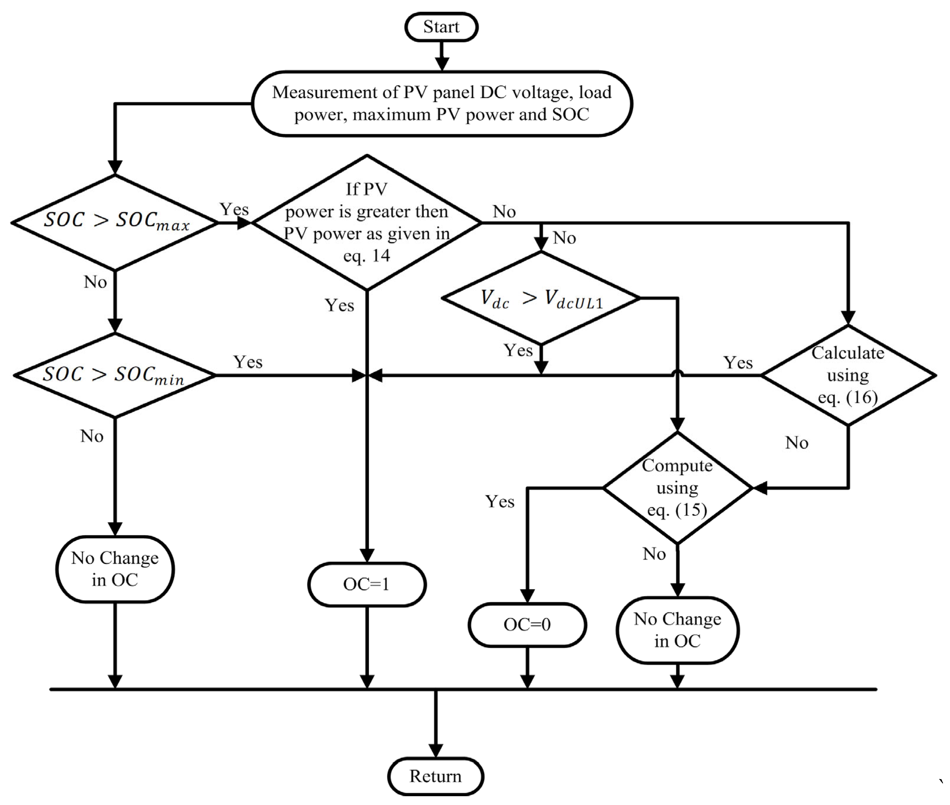
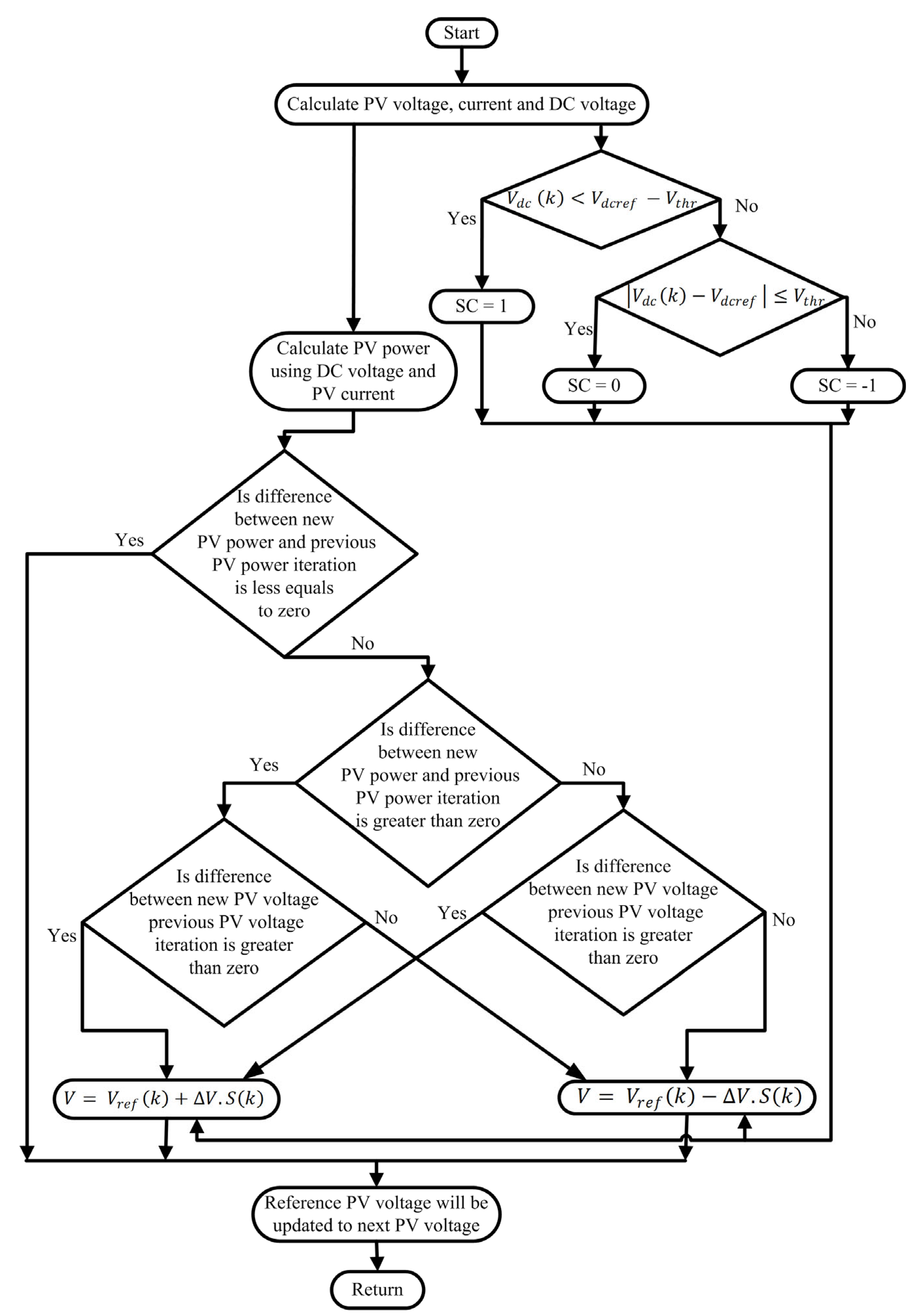
3.1.5. DCVA (DC-Link-Voltage-Based Algorithm) [47]

The DC-link-voltage-based algorithm (DCVA) is a hybrid control strategy, which is based on voltage control methodology. The schematic of the proposed DCVA is depicted in Figure 7. This technique regulates the DC bus voltage ( V d c ). First of all, the DC bus voltage ( V d c ), state of charge ( S o C ) , demand load power ( P l o a d ) and maximum PV panel power ( P p v m a x ) will be measured. If the V d c is not lying in the allowable range or the MPPT operating mode is on, then the ESS converter will operate. In this algorithm, V d c U L and V d c L L are the upper and lower limits of the control range, respectively. Moreover, a dead band exists around each of these control limits: V d c U L 1 and V d c U L 2 for V d c U L ; and V d c L L 1 and V d c L L 2 for V d c L L , respectively. If the S o C   is within the range of S o C m i n and S o C m a x , then there will be no change in operation condition (OC). Otherwise, if S o C is less than S o C m i n , then the value of the OC will be set as 1. When P l o a d is greater than the P p v m a x , as shown in Equation (14), then the OC will be equal to 1. In a scenario in which there is a failure of the last condition, the algorithm will check the condition   V d c >   V d c U L 1 , and if this condition is satisfied, then the OC will be equal to 1 again. In second situation, if Equation (15) is true, than it is the case that the OC will be equal to 0.
P l o a d > P p v m a x
  V d c U L 1 <   V d c <   V d c L L 2
V d c > V d c L L 2
If Equation (16) is within the range, i.e., within V d c U L 2 and V d c L L 1 , then the battery controller is switched off. Otherwise, the value of the OC will not change [47].

3.1.6. BSA (Binary Search-Based Algorithm) [48]

The binary search-based algorithm (BAS) is characterized by the iteration of voltage. The schematic diagram of the BSA is depicted in Figure 8. For each repetition, the main purpose is to evaluate the values V k   a n d   I k   to show the minimum and the maximum limits of the search window at the step-size of k, respectively. By using these values, the reference PV output voltage is determined by Equation (8). The PV array voltage ( V k ) and current ( i k ) are calculated for each repetition so as to estimate the PV output power ( P k ) in a manner similar to conventional MPPT and FPPT algorithms. Along with this, the error ( e k ) is evaluated, which is defined as the difference between the output power reference ( P k ) and ( P k 1 ). Moreover, calculations are performed to find the incremental values of the PV voltage and error from instants k − 1 to k, V k and   e k . Lastly, this technique requires the minimal error e m i n at the time of algorithm execution. The proposed approach will check for the new operating point if it is near the desired reference compared to the last point, as depicted in Equation (17) [48].
V k = 1 2 h k + l k
If this is true, then the e m i n and V m i n values will change, and the new variable e m i n will be evaluated. The value of e m i n is defined as difference between the minimum error obtained in the search process and the current error. Secondly, the algorithm will check whether the desired output power reference set point is changed or not. If e k > e m i n , then the values of e m i n and V m i n will be equal to e k and V k , respectively, the search window will be reset, and the flag f r s will be set to 1 so as to point out the reset process.

3.1.7. VSG-Control-Strategy-Based FPPT Algorithm [54]

The proposed algorithm is utilizing the disturbance observation method. The schematic diagram of the algorithm is depicted in Figure 9. Firstly, the values of the PV panel voltage ( V P V k ), PV panel current ( I d c k ) and dc bus voltage ( V d c ( k ) ) will be estimated. Further, the algorithm will check whether the value of V d c k is less than the difference of the reference DC voltage and the threshold voltage, which is given by V d c   k < V d c r e f V t h r .
If this condition is satisfied, then the value of the symbol of coefficient S C will set to 1. Otherwise, if this condition is not satisfied, then the algorithm will check that the mod value of the difference between the DC voltage and reference voltage is smaller than that of threshold voltage, as depicted in V d c   k V d c r e f V t h r . If it is, then the S C will be equal to 0. Otherwise, the value of S C will be set to −1. The power on both sides of the DC bus is balanced, and the DC bus voltage will remain stable [54].

3.2. Current-Based FPPT/CPG Control

This subsection contains the detailed explanation of the current-control-based FPPT/CPG method. In this technique, the point of operation is tracked by using current as a control parameter.

C-P&O-A (Current-Based P&O Algorithm) [43]

C-P&O-A (Current-based P&O algorithm) is based on a current control strategy. The way to control the PV output power is through the control of the PV output current i P V . The schematic flowchart of the current-based algorithm is illustrated in Figure 10. This is due to the fact that the PV voltage V P V only varies in a small range during the irradiance change in the operating region on the right side of the MPP (at the CPP-R). As a result, the PV output power P P V can be efficiently dealt with, as well as the PV output current i P V . So by using this control strategy, it is possible to attain a CPG operation by restricting the reference current from the MPPT algorithm i M P P T as per the limit current ( i l i m i t ) given by i l i m i t = P l i m i t V P V while evaluating the reference PV output current i P V . The current limit should not affect the controller’s performance while MPPT is being run. This can be achieved by using Equations (18) and (19) [43].
P M P P T V P V   P l i m i t V P V
and   thus ,   i M P P T i l i m i t
where the current limit will not be crossed since P M P P T P l i m i t , and the I-CPG technique in case of MPPT mode is reduced to a basic MPPT controller.

3.3. Power-Based FPPT/CPG Control

This sub-section consists of a detailed explanation of the power-based FPPT/CPG control. In this technique, the point of the operation is tracked by using power as a control parameter. The various voltage control-based techniques reported in the literature are explained in the following sub-sections.

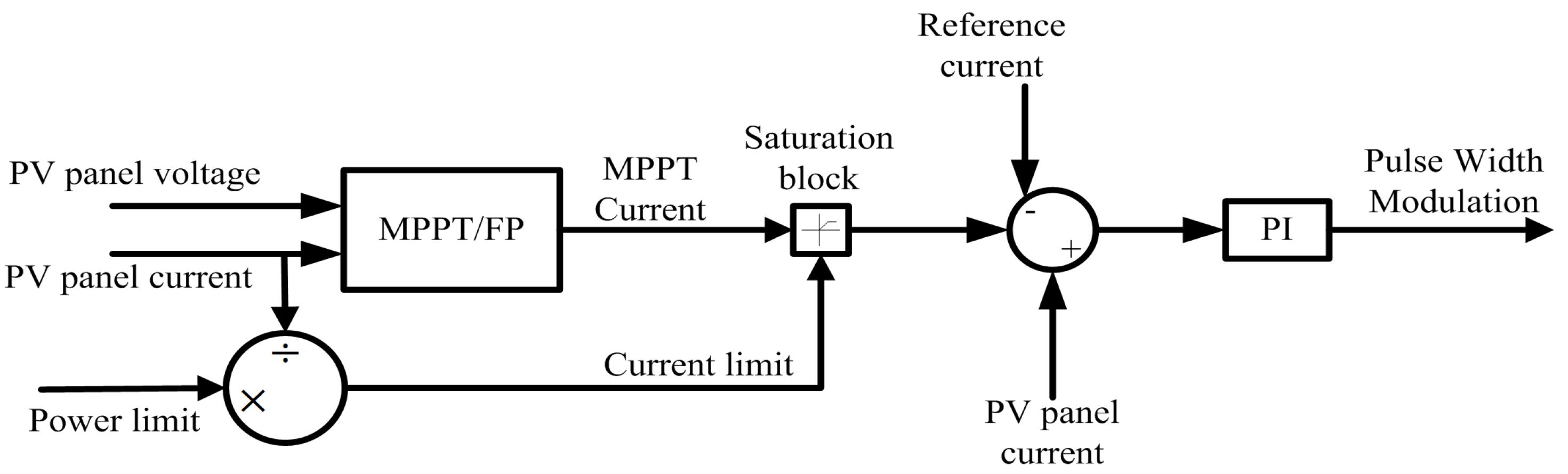
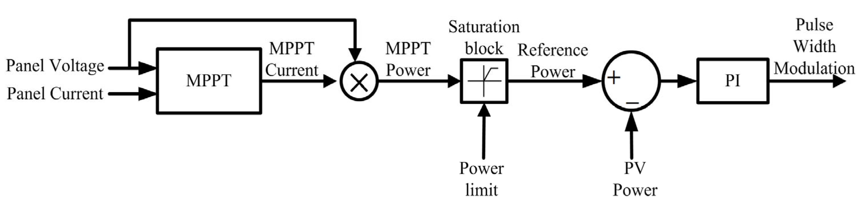
3.3.1. FVSA (Fixed-Voltage Step-Based Algorithm) [38]

Fixed-voltage step-based algorithm (FVSA) utilizes the P&O algorithm for the operational purpose. Figure 11 shows the flowchart of the voltage calculation to limit the extracted active power from the PV string under the fault-ride-through condition [38]. V is defined as V = V n e w V o l d , where V n e w is the PV voltage in the current time step, and V o l d is the PV string voltage in the last step-size. P is defined as P = P n e w P o l d , where P n e w is output power of the PV system in the current time step, and P o l d is the output power of the PV system in the previous step. All throughout MPPT mode, the time step T s t e p is set as a large value (e.g., 0.1 s) so that the steady-state oscillations can decrease. It is essential for the controller to decrease the power from the MPP value quickly while shifting to the RP mode. Hence, T s t e p is assigned to a small value ( T s t e p R P ) for RP operation mode. In the proposed algorithm, if the operating mode of DC/DC converter is MPPT, then V r e f = V M P P should be calculated using an MPPT algorithm. If the proposed algorithm needs to work on reduced power (RP), then the operating point should be on the right side of the MPP. By evaluating Δ P Δ V , it is realized that whether the existing operating point is on the left side or the right side of the MPP. Whenever the evaluated value is positive, the present operating point will be on the left side of the MPP, and the reference voltage for successive time step will be incremented ( V r e f = V r e f o l d + V s t e p R P ). The increment of V r e f in successive time steps will shift the operating point of the P-V curve to right side of the MPP. After obtaining the present operating point, the algorithm will calculate the voltage, which is dependent on P r e f .
Thus, P = P n e w P   r e f is evaluated in every time step. If the value of P is positive, then the output power is more than that of the reference power, so V r e f will increment in the next time step so as to reduce the output power. While, in the case of a negative P value, the reference voltage for next time step will decrement V r e f = V r e f _ o l d V s t e p _ R P to increase the output power.

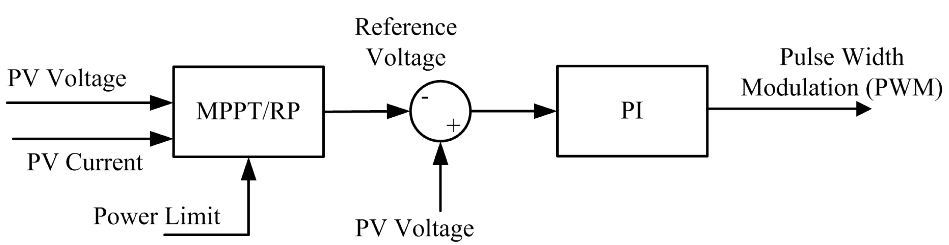
3.3.2. PRMA (Power-Reservation-Method-Based Algorithm) [39]

The power-reservation-method-based algorithm (PRMA) is a cost-effective constant-power generation method, in which it is realized that for power reserves, the PV system operate under CPG mode. In CPG mode, the operating point of the PV systems must be assigned below the MPP to satisfy P P V = P l i m i t . From the P–V curve illustrated in Figure 12, it is analyzed that there are two possibilities in operating points for a certain level of P l i m i t and irradiance level (i.e., A and C). But, it is observed that the operating point at the right side of the MPP (e.g., at C) can initiate instability in fast-changing irradiance (e.g., from 1000 to 200 W/m2, owing to passing clouds). In such a case, the open-circuit voltage of the PV panels V O C decreases as the irradiance level decreases, and the operating point may possibly plunge into (and stay at) the open-circuit condition (i.e., C→D). In this condition, the CPG operation will become unbalanced, and the PV system will not able to deliver any power to the grid. So, the operating point of the PV system is shifted to the left side of the MPP at the time of CPG operation. For CPG operation, the reference PV voltage V P V is determined by using Equation (20) [39]:
V P V = V M P P T   w h e n   P P V P l i m i t     V p v V s t e p   w h e n   P P V > P l i m i t    
where V M P P T is the reference voltage, and V s t e p is the voltage step-size.

3.3.3. P-P&O-A (Power-Based P&O Algorithm) [43,57]

The power-based P&O algorithm (P-P&O-A) is a control strategy that uses a closed-loop approach. At the time of MPPT operation, the PV output power P p v is easily controlled by applying the control strategy depicted in Figure 13. In this approach, the reference PV power of MPPT mode P M P P T is attained from the product of reference current i M P P T and PV voltage V p v . In the case of CPG mode, a saturation block is added to the control method so that the reference PV power P p v can be bound to a particular power level, i.e., P l i m i t . Specifically, when the reference PV power P M P P T is approaching the power limit P l i m i t , then the saturation block will keep the power reference stable, i.e., P p v = P l i m i t , and the CPG mode of the PV system is achieved. Otherwise, if the reference P M P P T is less than P l i m i t , then saturation block will not work, and the PV system will run in the MPPT mode with the highest power injection (i.e., P p v = P M P P T ), which is correspondent to the MPPT controller, as shown in Equation (21) [43]:
P p v = P M P P T ,   w h e n   P M P P T P l i m i t P l i m i t , w h e n   P M P P T > P l i m i t
where P M P P T is the utmost accessible power (as per the MPPT operation), and P l i m i t is the power limit, as defined earlier.

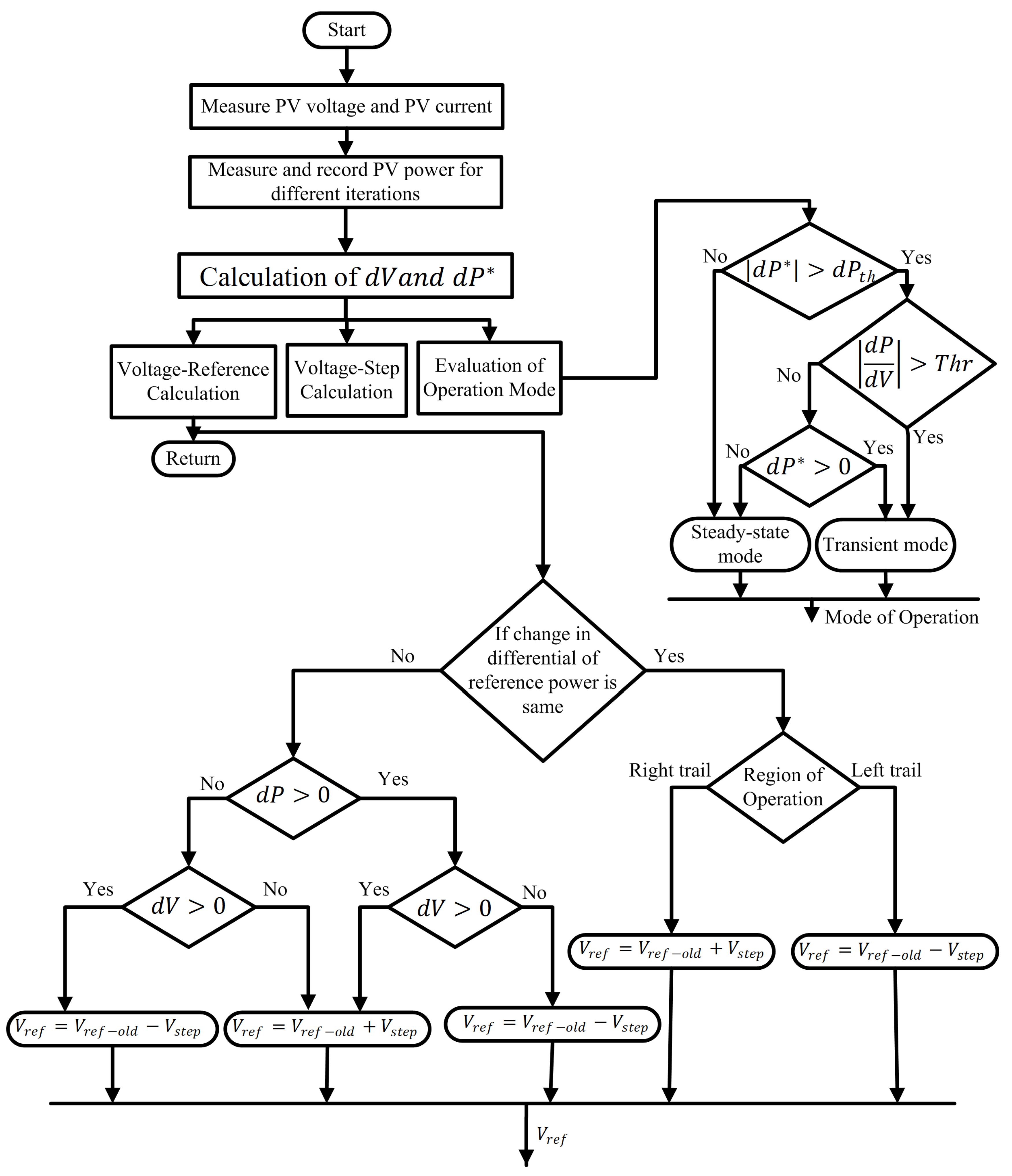
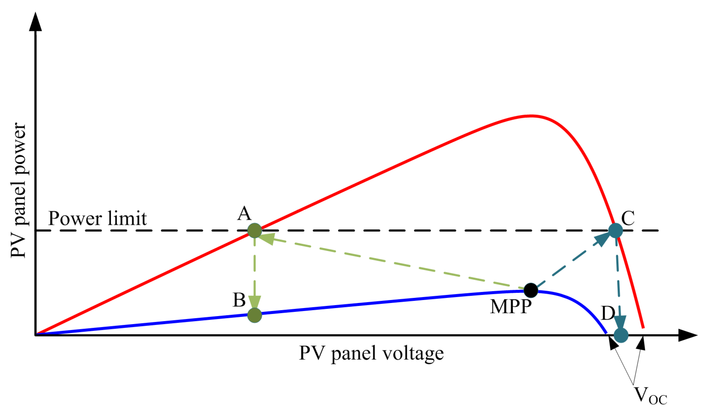
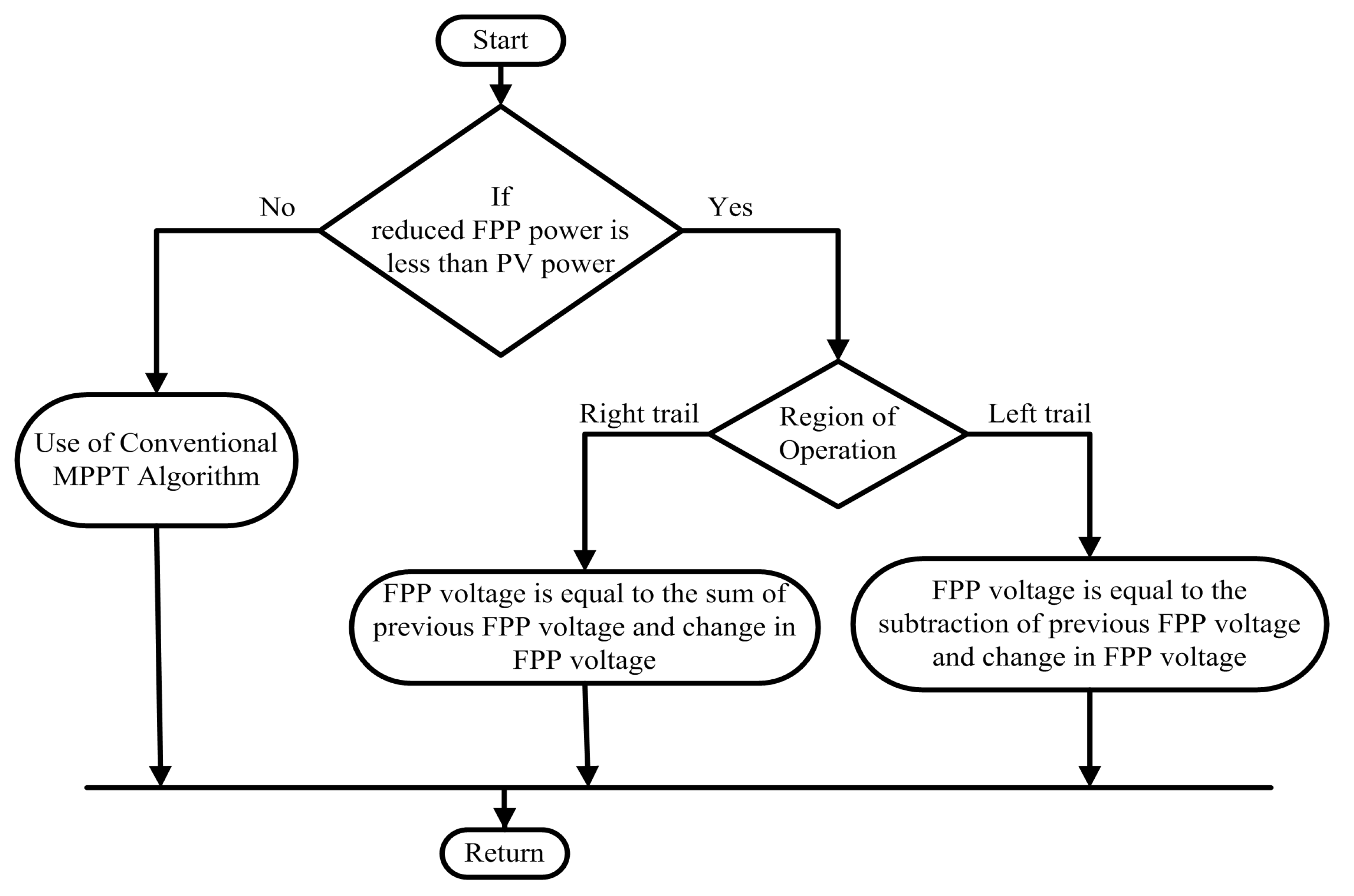
3.3.4. MMPA (Multi-Mode Power-Based Algorithm) [46]

The multi-mode power-based algorithm (MMPA) uses the power control strategy for its operation, as shown in Figure 14. The accomplishment of the proposed work is based on the relationship between PV power P p v and power reference P f p p , i.e., P f p p < P p v . If this condition fails, then the algorithm will utilize the traditional MPPT algorithm for its operation. But if this condition is true, then the control algorithm will cause the power to decrease. So, to decrease the power, the designed technique will choose its operation, and the previously achieved MPP voltage reference V f p p o l d will be utilized for further implementation. If the control strategy works on left-hand side of the MPP, then a drop in PV power is realized by replacing the evaluated V from V f p p o l d   V f p p = V f p p o l d V . Additionally, V is calculated by utilizing a PI controller. The input of this PI controller is the error between the PV power P p v and power reference P f p p . Otherwise, if the control strategy works on right-hand side of the MPP, then an increase in PV power is realized by replacing the evaluated V from V f p p o l d   V f p p = V f p p o l d + V .

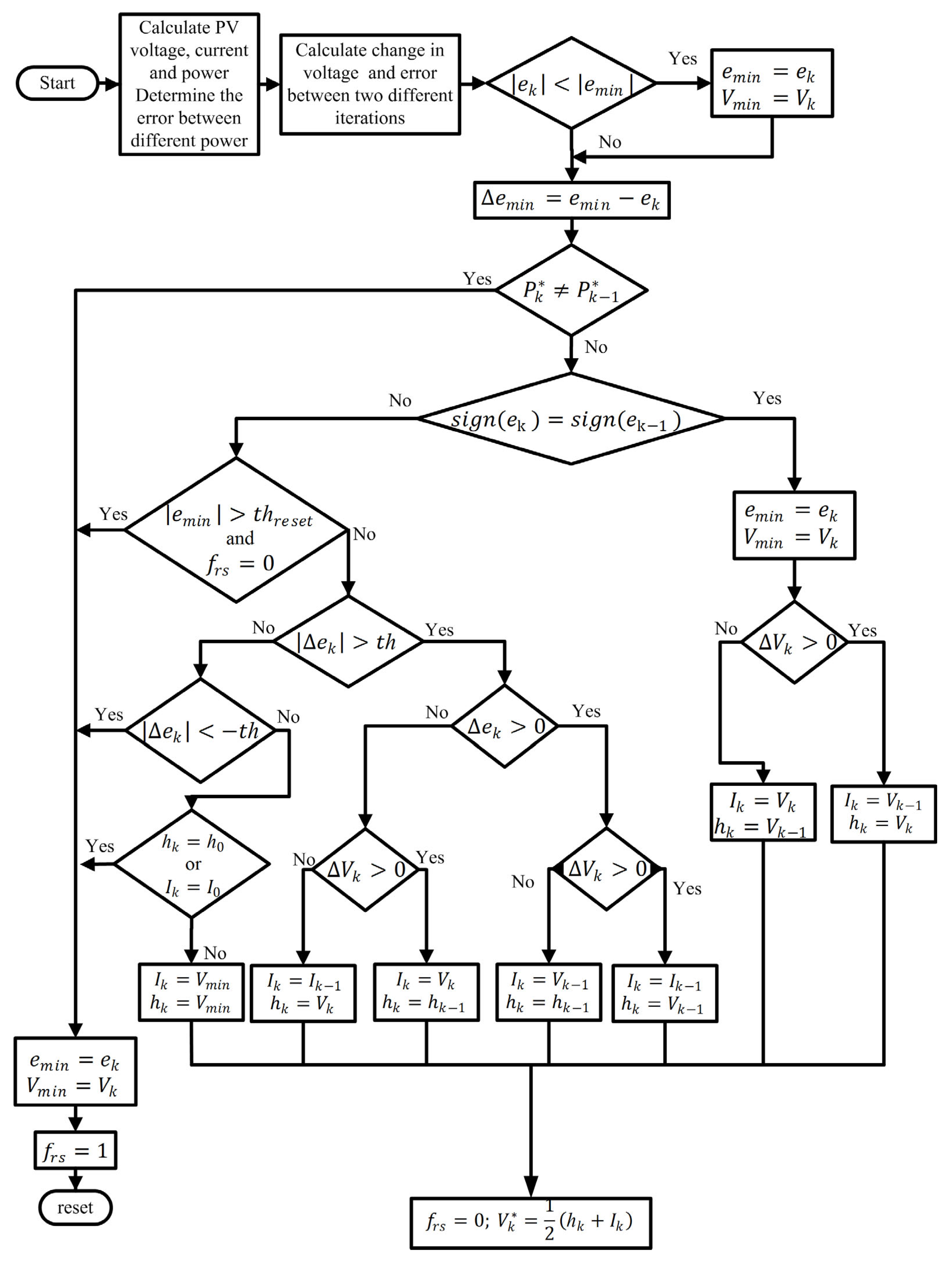
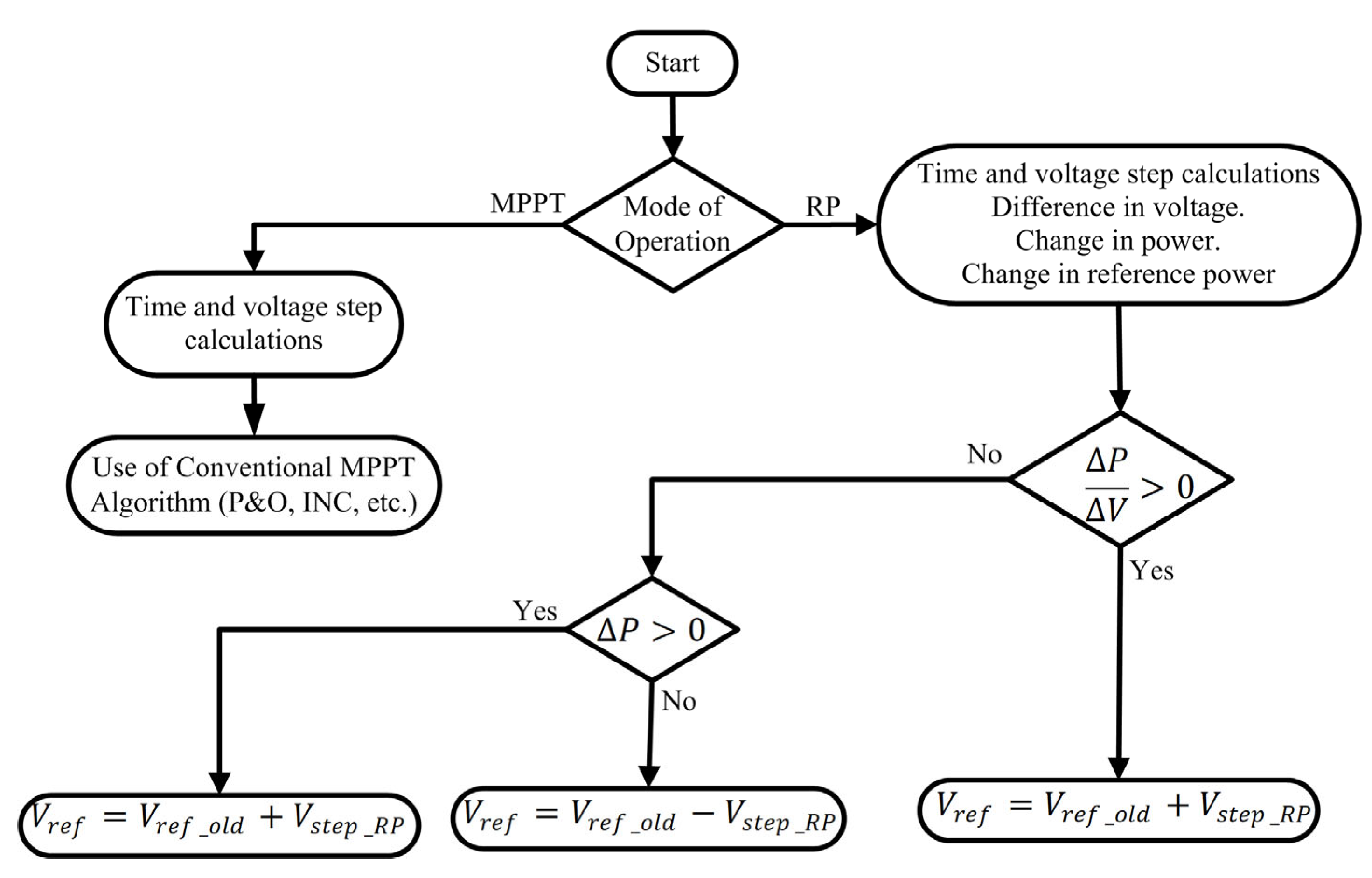
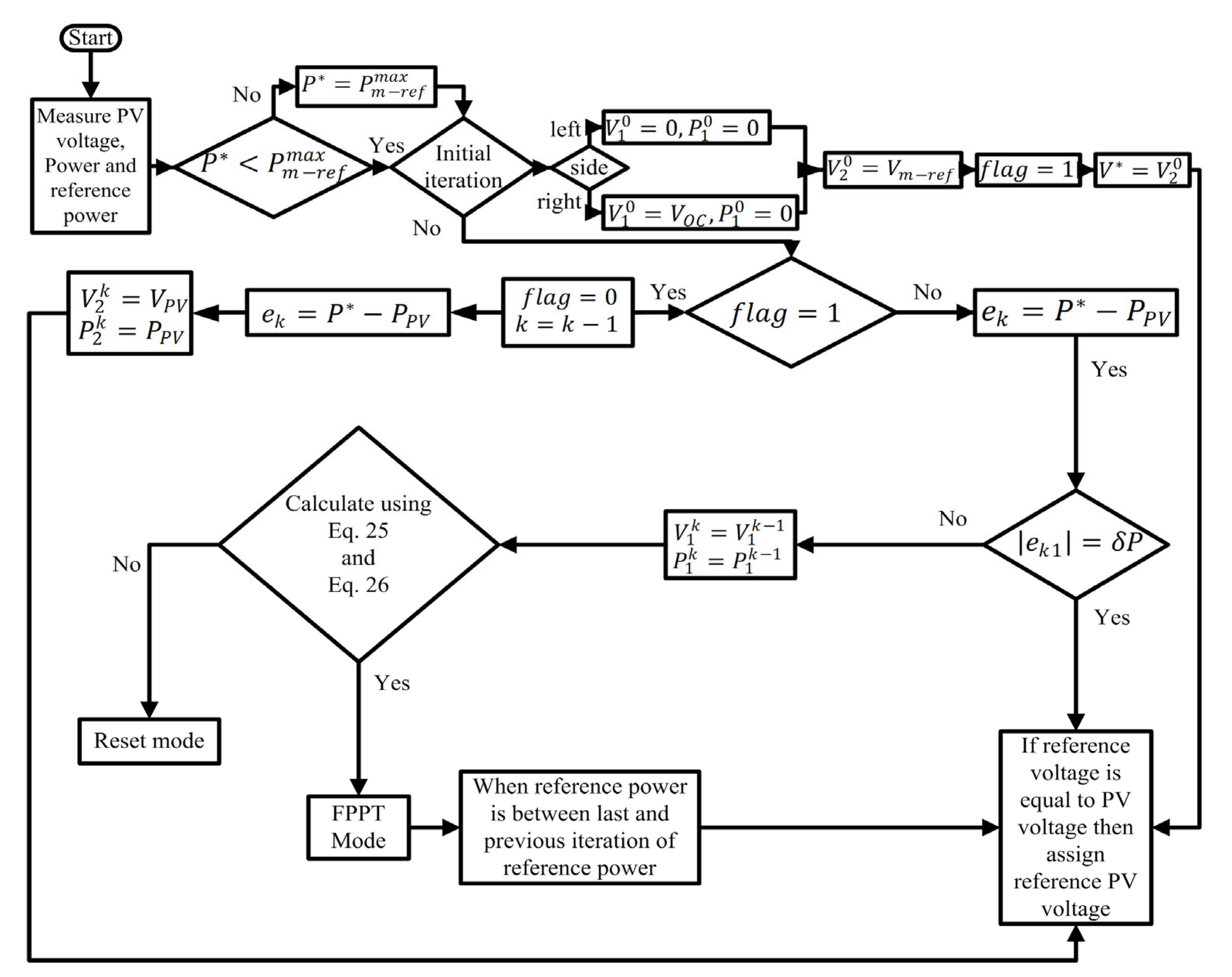
3.3.5. SMA (Secant-Method-Based Algorithm) [49]

A secant-method-based algorithm (SMA) schematic diagram is illustrated in Figure 15. First of all, the PV parameters will be evaluated. Further, the algorithm will check weather P is smaller than P m r e f m a x   to make sure that V is lying in a range, in which the controller is capable of trailing it by using Equation (22) [49].
V = V 1 k + V 2 k V 1 k P P 1 k P 2 k P 1 k
where k = 0, 1, 2,… and so on.
Moreover, the basic conditions for the proposed method are predetermined based on the side of the operation, as defined in Equation (23). The subsequent values in Equation (23) are defined as follows [49]:
l e f t   s i d e : V 1 0 = 0 P 1 0 = 0 V 2 0 = V m r e f P 2 0 = P m r e f , r i g h t   s i d e : V 1 0 = V O C P 1 0 = 0 V 2 0 = V m r e f P 2 0 = P m r e f
It is realized that P m r e f can be replaced with P 2 0 , which is unidentified. Thus, V m r e f is set as V . The PV voltage V P V is achieved by tracking V . To track V , the last repetition’s V 2 k replaces V P V , and P 2 k replaces P p v . Then, in the next step, the point ( V 2 0 , P 2 0 ) is replaced by ( V 2 1 , P 2 1 ), and the procedure will carry on. Same tracking method is followed for the operation on both the left and right trail of the P-V curve, but it differs in the initial search range. The error is realized again and again for every repetition, and it is calculated by using Equation (24) [49].
e k = P P P V
where e k is the error in each step, and P P V is power of PV panel.
It can be concluded that the conditions given in Equations (25) and (26) need to be satisfied for the solution to converge [49]:
| e k 1 | > | e k |
and   S i g n e k 1 = S i g n e k
This method will only converge to a specified range of reference curve settings and not for power reference values. If a different operating curve is to be used for different conditions, then the proposed method might not work when   P m r e f < P < P m a c t , as P m a c t will be greater than   P m r e f , and the controller would be recognizing that P m r e f   is the most possible power output for the existing environmental situations.

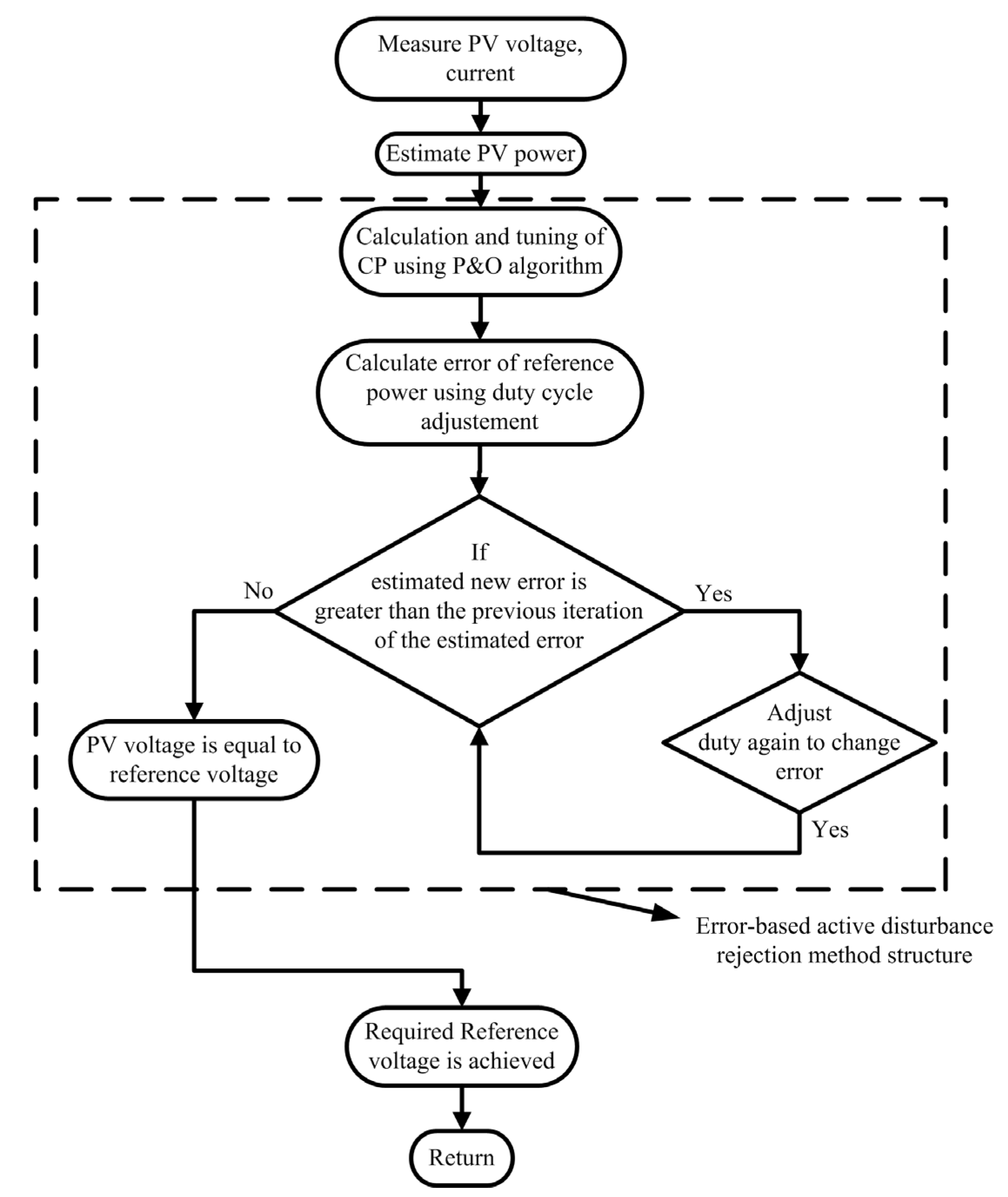
3.3.6. EADRA (Error-Based Active Disturbance Rejection Algorithm) [50]

The error-based active disturbance rejection algorithm (EADRA) works on the strategy of error disturbance and the rejection algorithm. The algorithm is simply explained in a theoretical form and depicted in Figure 16.
The functioning of this algorithm mainly depends on three key points i.e., power tracking, tuning of parameters for EADRC and the duty cycle’s adjustment. The focus of the algorithm is to achieve a voltage reference V r e f that corresponds to   P r e f . The operational point of the algorithm is achieved by regulating the disturbance direction, and it uses the P&O algorithm for the ability to choose between MPPT and CPG.
First of all, the operation of the algorithm will begin by checking the condition i.e., P r e f   P a v a i l . If the condition is true, then the voltage change will be tracked by using the P&O algorithm until V r e f = V P V m a x . Otherwise, if P r e f < P a v a i l , the voltage reference under the stable operating point is realized in accordance with the operating interval. A large step-size in the P&O algorithm will lead to huge fluctuations in power and voltage, and a small step-size will restrict the speed of the strategy. A realistic step-size is, therefore, necessary to enhance the performance of the CPG method. Extensive testing reveals that the outcome is satisfactory when the step-size is 0.2 in order to establish a good balance between fluctuation and speed. The major components of duty cycle modification are the EADRC and PWM drive circuit. Based on the voltage inaccuracy and real-time current measured at the input, EADRC provides a current adjustment signal. The boost converter’s duty cycle will be continually modified due to the boost principle until P o u t = P r e f . The optimization process aims to produce a set of optimal controller parameters.

3.3.7. HC&PSO-A (HC- and PSO-Based Algorithm) [51]

Hill-climbing- and particle-swarm-optimization-based algorithm (HC&PSO-A) is working on the basis of the hill-climbing approach and particle swarm intelligence. The schematic diagram of this algorithm is shown in a flowchart form in Figure 17.
In this technique, the parameters are assigned as S , T , P r e f , V P V ( i ) , and the calculation is performed using the hill-climbing approach as shown in Figure 17. In the HCA (hill-climbing algorithm), a randomly initialized voltage is taken as V o l d , which is used to obtain V n e w = V o l d + V s t e p , where V s t e p is the step voltage or a step-size. Further, the increment and decrement of the new voltage ( V n e w ) is dependent on the condition given in Equation (27) [51]:
Check   if   P V o l d > P ( V n e w )
If this condition is true, then V n e w will increment by V s t e p as V n e w = V o l d + V s t e p , otherwise V n e w will decrement by V s t e p as V n e w = V o l d V s t e p . The output power P V n e w will be dependent on the increment or decrement of the new voltage.
The HCA is used to perform the calculation of the matrix of turning points as shown in Figure 17. After these evaluations, the reference voltage V r e f will be calculated by satisfying the Equation (28) [51].
P f p p > P P V
where P f p p is power at FPP, and P P V is the PV panel power.
The reference voltage ( V r e f ) is calculated by using PSOA (particle swarm optimization-based algorithm), in which the reference voltage will be updated by completing iterations again to reach the required voltage ( V M P P ). Along with these calculations, the duty cycle will be controlled by PWM (pulse width modulation) to achieve the required PV voltage control.

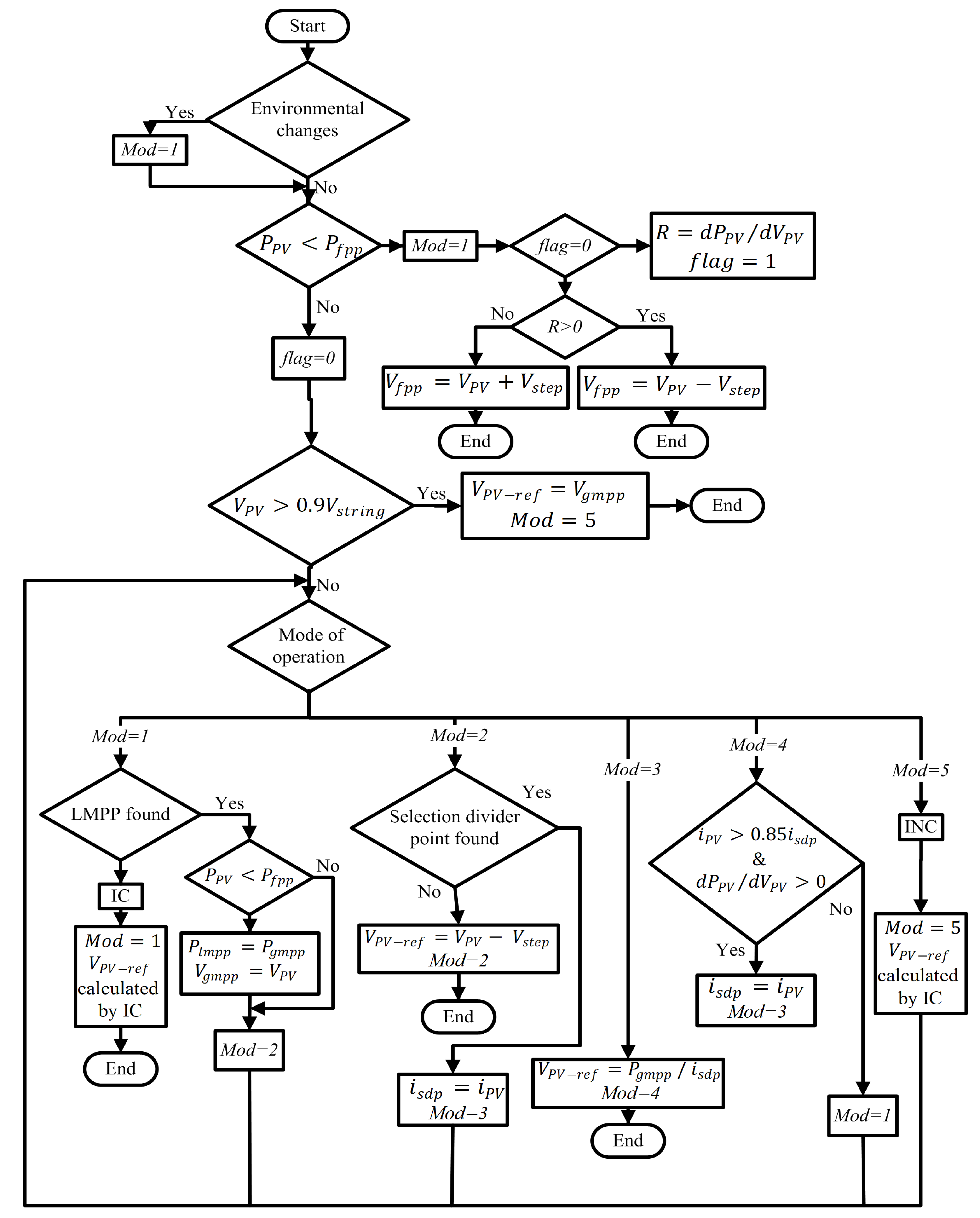
3.3.8. NGA-PSC (Novel Global Algorithm under Partial Shading Conditions) [53]

Novel global algorithm under partial shading conditions (NGA-PSC) is illustrated in flowchart form in Figure 18. Assuming no environmental change, the algorithm will check if P P V > P f p p ; if it is true, the operating mode (Mod) is set to 1. A variable flag is utilized, and initial value of flag is set to zero ( f l a g = 0 ). Following this case, the slope of the P-V curve is evaluated ( R = d P P V / d V P V ) , and the value of flag is set to 1 ( f l a g = 1 ). The algorithm is designed in such a way that if R > 0 , the operating point will lie on the left side of the P-V curve, and V f p p will increment by V s t e p , given as V f p p = V P V + V s t e p . Otherwise, V f p p will decrement by V s t e p , given as   V f p p = V P V V s t e p .
The operation mode can be selected by testing the conditions mentioned in Equation (29). If Equation (28) is satisfied, then the reference voltage V P V r e f   will be set at the global MPP voltage ( V g m p p ) , and M o d will be set to 5, as depicted in Figure 18 [53].
V P V > 0.9 V s t r i n g
If P P V > P f p p is not satisfied, the selection of the operation mode will be required. The operation mode can be either 1, 2, 3, 4 or 5, as shown in the algorithm depicted in Figure 18.

3.3.9. MA (Model-Based Algorithm) [55]

The model-based algorithm (MA) for dual-mode power generation of the two-stage PV system is depicted in Figure 19. For the operation of the algorithm, initially, the inputs, PV panel voltage and current, as well as the temperature are set as V P V k , i P V k , T , respectively, and the PV panel power is defined as P P V = V P V k . i P V k . If P P V > P r e f , then ∆P will be set as 0 (here, P is the difference between the panel power and power reference, i.e., P = P P V P r e f ). Initially,   P = 0 , but if P > 0 , then d (duty cycle) will decrement. Otherwise, d will increment. In another case, if P P V > P r e f is false, then a radiation estimation needs to be conducted as shown in the flowchart of the algorithm. Further, ∆V will set as 0 (here, V = V m l V P V ( k ) ), but if V > 0 , then d (duty cycle) will increment. Otherwise, d will decrement.

4. Comparative Analysis

In the previous section various algorithms were discussed in detail. These control strategies are grouped under three categories, namely voltage-based, current-based and power-based control methods, in the three subsections above, respectively. All these strategies are used to track the FPP/CPP at the time of intermittency occurring in grid-connected PV systems. Basically, these strategies work to achieve active power curtailment to stabilize grid-connected PV systems. In a nutshell, the active power is reduced as per the specifications of grid codes, and so is the reactive power, to be injected into the grid [1,51,52,53,54]. In this section, the comparative analysis of voltage/current/power-based FPPT/CPG control is performed in detail. A performance-metrics-based study is conducted for the ease of this comparative analysis. The performance parameters, like irradiance pattern (G), region of operation, speed of tracking, steady-state power oscillations, drift severity, partial shading scenario, implementation complexity, cost and tracking efficiency, are considered to carry out this comparative analysis [64]. Table 3 shows the comparative analysis of the various CPG/FPPT approaches considering the above-mentioned performance parameters.
Most of the work is completed by tracking the MPP and doing power curtailment at the time of intermittency occurrence. In general, the step- or ramp-type irradiance patterns are followed, and the region of the operation is set at either the left or right trail of the P-V curve. Along with that, in most of the cited works, the speed of tracking is medium, and the steady-state oscillations are high. Also in most of the works, the implementation complexity is high, and so is the cost. Moreover, these techniques do not address the drift severity issues and partial shading scenario for the implementation of the proposed FPPT techniques. In 2020, it has been realized that among all the algorithms, Gomez-Merchan et al. had achieved an efficiency of 77.56% by using the binary-search FPPT-based technique. The above-mentioned technique has the minimum tracking efficiency compared to the others [48]. The maximum efficiency of 99.13% is achieved by Hou et al. in 2021. The authors had used the error-disturbance-based P&O FPPT control method to attain this high of an efficiency [50]. In 2022, Ahmed et al. has achieved the second-highest tacking efficiency of 98.57% [55].

5. Conclusions and Future Scope of Work

This review mainly focuses on the detailed comprehensive study of various algorithms for FPPT/CPG reported in the literature. The comparative analysis is performed on the basis of three different categories, namely voltage-based control, current-based control and power-based control strategies. Further, a deep comparison of these algorithms is conducted by considering various performance parameters, like the type of control strategy, irradiance pattern, variation in G, region of operation, speed of tracking, steady-state power oscillations, drift severity scenario, partial shading scenario, implementation complexity, stability, fast dynamic response, robustness, reactive power, cost and tracking efficiency.
From this deep analysis, it has been realized that among the entire lot of algorithms compared, model-based MPPT and FPPT control is better in terms of performance. This method was proposed by Ahmed et al. [55]. They have achieved a maximum tracking efficiency of 98.57%, with high tacking speed and reduced steady-state power oscillations. A step-type irradiance pattern is followed to test their algorithm, and the region of operation is on the right trail of the P-V curve. But stability is less, and reactive power is also not considered at the time of FPP operation due to the proposed algorithm not being robust. But the overall performance of the algorithm is better among all the other methods.
However, stability, robustness, the effect of partial shading scenario and drift severity scenario can be addressed in further works. The simulation and hardware implementation can then be accomplished by using these conditions to achieve a robust PV system.
In this review, a comparative study is carried out for different FPPT control strategies. The insight developed from this study suggests further work is required on the following aspects:
  • Existing adaptive FPPT algorithms use two distinct step-sizes, and the scope is available to develop a generalized FPPT algorithm that rapidly tracks the FPP with low steady-state oscillations by appropriately selecting a perturbation step-size and adaptively varying it for an improved tracking performance.
  • Until now, most of the work is completed by making use of conventional algorithms with a little bit of modification. However, further considerations can be performed with a scope of novelty in the control strategies for the enhancement of the tracking efficiency and for the reduction in oscillations.
  • In the literature, only a few of the works have considered the drift severity issue, and its solution has not been explored much. So, a thorough addressing of the drift severity is an area requiring further studies, especially in a case of multiple PV arrays.
  • It has already been concluded that the above-discussed algorithms are implemented and tested using conventional algorithms under ideal environmental conditions, like changing irradiance patterns and temperature. But still there is room to explore control strategies in such a way that can work under partial shading scenarios.
  • Furthermore, from the application point of view, improvements in the above-discussed techniques can be suggested to make grid-forming (GFM) converters and PV inverters suitable for seamless switching between MPPT and FPPT solutions to deal with low-voltage ride-through (LVRT) conditions occurring in grid-tied PV systems.

Author Contributions

Conceptualization, S.S. and V.J.; methodology, S.S.; software, S.S.; formal analysis, P.K. (Piyush Kuchhal); investigation, S.S., V.J. and P.K. (Peeyush Kala); resources, P.K. (Piyush Kuchhal); data curation, S.S. and V.J.; writing—original draft preparation, S.S.; writing—review and editing, V.J., P.K. (Piyush Kuchhal) and P.K. (Peeyush Kala); supervision, P.K. (Piyush Kuchhal) and B.A.; project administration, B.A.; funding acquisition, B.A. All authors have read and agreed to the published version of the manuscript.

Funding

This research received no external funding.

Data Availability Statement

Not applicable.

Acknowledgments

This work is supported in part by the European Commission H2020 TWINNING JUMP2Excel (Joint Universal activities for Mediterranean PV integration Excellence) project under grant 810809. Partly funded by the European Union under Grant 101079469 PROMISE “Photovoltaics Reliability Operations and Maintenance Innovative Solutions for Energy Alliance” project. Views and opinions expressed are however those of the author(s) only and do not necessarily reflect those of the European Union and/or UKRI. Neither the European Union nor UKRI nor the granting authority can be held responsible for them. Partly funded by the European Union under Grant 101075747 and UK Research and Innovation (UKRI) TRANSIT “TRANSITion to sustainable future through training and education” project. Views and opinions expressed are however those of the author(s) only and do not necessarily reflect those of the European Union and/or UKRI. Neither the European Union nor UKRI nor the granting authority can be held responsible for them. The authors would like to thank UPES, Dehradun, India to provide support to carry out this research work under project code UPES/R&D-SOE/07032022/07. Energies 16 05679 i001

Conflicts of Interest

The authors declare no conflict of interest.

Abbreviations

CPG: Constant power generationMPC: Model predictive control
CPS: Constant power sourceMPP: Maximum power point
CPP: Constant power pointMPPT: Maximum power point tracking
FPPT: Flexible power point trackingP&O: Perturb and observe
FPP: Flexible power pointPSC: Partial shading conditions
GMP: Global maximum powerPV: Photovoltaics
INC: Incremental conductancePWM: Pulse width modulation
INR: Incremental resistanceSTC: Standard test conditions
G: Irradiance P l o a d : Load demand power
GFM: Grid-forming converters P p v m a x / P M P P / P P V : Maximum PV panel power
d P : Differential of reference power P m a c t : Acting MPP power for particular value of irradiance and temperature.
d P t h : Threshold power P m r e f : Real power at V m r e f
e k : Error (in each iteration) P t h : Operation boundary of reference power
I P V : PV panel currentRP: Reduced power
J S C : Short-circuit current density of the PV panel S o C : State of charge
P : Power reference S ( k ) : Symbol of coefficient
P f p p : Power at FPP V m a c t : Acting voltage for the particular value of irradiance and temperature
T: Temperature V O C : Open circuit voltage of the PV panel
T s t e p : Time step between different operating points V P V : PV panel voltage
V / V p v   V m r e f : Voltage reference V s t e p : Voltage step between different operating point
V d c : DC bus voltage

References

  1. Talha, M.; Raihan, S.R.S.; Rahim, N.A.; Akhtar, M.N.; Butt, O.M.; Hussain, M.M. Multi-Functional PV Inverter with Low Voltage Ride-Through and Constant Power Output. IEEE Access 2022, 10, 29567–29588. [Google Scholar] [CrossRef]
  2. Parlevliet, D.; Moheimani, N.R. Efficient conversion of solar energy to biomass and electricity. Aquat. Biosyst. 2014, 10, 4. [Google Scholar] [CrossRef] [PubMed]
  3. Chen, P.-C.; Liu, Y.-H.; Chen, J.-H.; Luo, Y.-F. A comparative study on maximum power point tracking techniques for photovoltaic generation systems operating under fast changing environments. Sol. Energy 2015, 119, 261–276. [Google Scholar] [CrossRef]
  4. Peng, B.-R.; Ho, K.-C.; Liu, Y.-H. A Novel and Fast MPPT Method Suitable for Both Fast Changing and Partially Shaded Conditions. IEEE Trans. Ind. Electron. 2017, 65, 3240–3251. [Google Scholar] [CrossRef]
  5. Du, Y.; Li, X.; Wen, H.; Xiao, W. Perturbation optimization of maximum power point tracking of photovoltaic power systems based on practical solar irradiance data. In Proceedings of the 2015 IEEE 16th Workshop on Control and Modeling for Power Electronics (COMPEL), Vancouver, BC, Canada, 12–15 July 2015; pp. 1–5. [Google Scholar]
  6. Ahmed, J.; Salam, Z. A Modified P&O Maximum Power Point Tracking Method with Reduced Steady-State Oscillation and Improved Tracking Efficiency. IEEE Trans. Sustain. Energy 2016, 7, 1506–1515. [Google Scholar]
  7. Ahmed, J.; Salam, Z. An Enhanced Adaptive P&O MPPT for Fast and Efficient Tracking under Varying Environmental Conditions. IEEE Trans. Sustain. Energy 2018, 9, 1487–1496. [Google Scholar]
  8. Urtasun, A.; Sanchis, P.; Marroyo, L. Limiting the power generated by a photovoltaic system. In Proceedings of the 2013 10th International Multi-Conference on Systems, Signals & Devices (SSD), Hammamet, Tunisia, 18–21 March 2013; pp. 1–6. [Google Scholar]
  9. Kouro, S.; Leon, J.I.; Vinnikov, D.; Franquelo, L.G. Grid-Connected Photovoltaic Systems: An Overview of Recent Research and Emerging PV Converter Technology. IEEE Ind. Electron. Mag. 2015, 9, 47–61. [Google Scholar] [CrossRef]
  10. Batzelis, E.I.; Kampitsis, G.E.; Papathanassiou, S.A. Power Reserves Control for PV Systems with Real-Time MPP Estimation via Curve Fitting. IEEE Trans. Sustain. Energy 2017, 8, 1269–1280. [Google Scholar] [CrossRef]
  11. Forouzesh, M.; Siwakoti, Y.P.; Gorji, S.A.; Blaabjerg, F.; Lehman, B.J. Step-up DC–DC converters: A comprehensive review of voltage-boosting techniques, topologies, and applications. IEEE Trans. Power Electron. 2017, 32, 9143–9178. [Google Scholar] [CrossRef]
  12. Mei, Q.; Shan, M.; Liu, L.; Guerrero, J.M. A Novel Improved Variable Step-Size Incremental-Resistance MPPT Method for PV Systems. IEEE Trans. Ind. Electron. 2010, 58, 2427–2434. [Google Scholar] [CrossRef]
  13. Wang, H.; Shen, J. An Improved Model Combining Evolutionary Algorithm and Neural Networks for PV Maximum Power Point Tracking. IEEE Access 2018, 7, 2823–2827. [Google Scholar] [CrossRef]
  14. Park, S.M.; Park, S.Y. Power weakening control of the photovoltaic-battery system for seamless energy transfer in microgrids. In Proceedings of the 2013 Twenty-Eighth Annual IEEE Applied Power Electronics Conference and Exposition (APEC), Long Beach, CA, USA, 17–21 March 2013; pp. 2971–2976. [Google Scholar]
  15. Tonkoski, R.; Lopes, L.A.C.; El-Fouly, T.H.M. Coordinated Active Power Curtailment of Grid Connected PV Inverters for Overvoltage Prevention. IEEE Trans. Sustain. Energy 2011, 2, 139–147. [Google Scholar] [CrossRef]
  16. Blaabjerg, F.; Teodorescu, R.; Liserre, M.; Timbus, A.V. Overview of Control and Grid Synchronization for Distributed Power Generation Systems. IEEE Trans. Ind. Electron. 2006, 53, 1398–1409. [Google Scholar] [CrossRef]
  17. Yang, Y.; Blaabjerg, F.; Zou, Z. Benchmarking of Grid Fault Modes in Single-Phase Grid-Connected Photovoltaic Systems. IEEE Trans. Ind. Appl. 2013, 49, 2167–2176. [Google Scholar] [CrossRef]
  18. Coster, E.J.; Myrzik, J.M.A.; Kruimer, B.; Kling, W.L. Integration Issues of Distributed Generation in Distribution Grids. Proc. IEEE 2010, 99, 28–39. [Google Scholar] [CrossRef]
  19. Islam, G.M.S.; Al-Durra, A.; Muyeen, S.; Tamura, J. Low voltage ride through capability enhancement of grid connected large scale photovoltaic system. In Proceedings of the IECON 2011—37th Annual Conference of the IEEE Industrial Electronics Society, Melbourne, Australia, 7–10 November 2011; pp. 884–889. [Google Scholar]
  20. Rosa, C.; Vinikov, D.; Romero-Cadaval, E.; Pires, V.; Martins, J. Low-power home PV systems with MPPT and PC control modes. In Proceedings of the 2013 International Conference-Workshop Compatibility and Power Electronics, Ljubljana, Slovenia, 5–7 June 2013; pp. 58–62. [Google Scholar]
  21. Albarracín, R.; Alonso, M. Photovoltaic reactive power limits. In Proceedings of the 2013 12th International Conference on Environment and Electrical Engineering, Wroclaw, Poland, 5–8 May 2013; pp. 13–18. [Google Scholar]
  22. Li, X.; Wang, Q.; Wen, H.; Xiao, W. Comprehensive Studies on Operational Principles for Maximum Power Point Tracking in Photovoltaic Systems. IEEE Access 2019, 7, 121407–121420. [Google Scholar] [CrossRef]
  23. Podder, A.K.; Roy, N.K.; Pota, H.R. MPPT methods for solar PV systems: A critical review based on tracking nature. IET Renew. Power Gener. 2019, 13, 1615–1632. [Google Scholar] [CrossRef]
  24. Chinchilla, M.; Arnalte, S.; Burgos, J.; Rodríguez, J. Power limits of grid-connected modern wind energy systems. Renew. Energy 2006, 31, 1455–1470. [Google Scholar] [CrossRef]
  25. Wandhare, R.G.; Agarwal, V. Precise active and reactive power control of the PV-DGS integrated with weak grid to increase PV penetration. In Proceedings of the 2014 IEEE 40th Photovoltaic Specialist Conference (PVSC), Denver, CO, USA, 8–13 June 2014; pp. 3150–3155. [Google Scholar]
  26. Jately, V.; Arora, S. Development of a dual-tracking technique for extracting maximum power from PV systems under rapidly changing environmental conditions. Energy 2017, 133, 557–571. [Google Scholar] [CrossRef]
  27. Zater, M.E.; Adwan, A. Online Gradient Descent for Flexible Power Point Tracking Under a Highly Fluctuating Weather and Load. arXiv 2022, arXiv:2203.00197. [Google Scholar]
  28. Timbus, A.V.; Teodorescu, R.; Blaabjerg, F.; Liserre, M.; Rodriguez, P. PLL algorithm for power generation systems robust to grid voltage faults. In Proceedings of the 2006 37th IEEE Power Electronics Specialists Conference, Jeju, Republic of Korea, 18–22 June 2006; pp. 1–7. [Google Scholar]
  29. Grid-Connected PV Systems: Design and Installation; Global Sustainable Energy Solutions Pvt. Limited: New Delhi, India, 2013.
  30. Craciun, B.-I.; Kerekes, T.; Sera, D.; Teodorescu, R. Frequency Support Functions in Large PV Power Plants with Active Power Reserves. IEEE J. Emerg. Sel. Top. Power Electron. 2014, 2, 849–858. [Google Scholar] [CrossRef]
  31. Tang, C.Y.; Chen, Y.T.; Chen, Y.M. PV Power System with Multi-Mode Operation and Low-Voltage Ride-Through Capability. IEEE Trans. Ind. Electron. 2015, 12, 7524–7533. [Google Scholar] [CrossRef]
  32. Tafti, H.D.; Maswood, A.I.; Konstantinou, G.; Pou, J.; Kandasamy, K.; Lim, Z.; Ooi, G.H. Low-voltage ride-thorough capability of photovoltaic grid-connected neutral-point-clamped inverters with active/reactive power injection. IET Renew. Power Gener. 2017, 11, 1182–1190. [Google Scholar] [CrossRef]
  33. Yang, Y.; Koutroulis, E.; Sangwongwanich, A.; Blaabjerg, F. Pursuing Photovoltaic Cost-Effectiveness: Absolute Active Power Control Offers Hope in Single-Phase PV Systems. IEEE Ind. Appl. Mag. 2017, 23, 40–49. [Google Scholar] [CrossRef]
  34. Mirhosseini, M.; Pou, J.; Karanayil, B.; Agelidis, V.G. Resonant Versus Conventional Controllers in Grid-Connected Photovoltaic Power Plants Under Unbalanced Grid Voltages. IEEE Trans. Sustain. Energy 2016, 7, 1124–1132. [Google Scholar] [CrossRef]
  35. Kakimoto, N.; Takayama, S.; Satoh, H.; Nakamura, K. Power Modulation of Photovoltaic Generator for Frequency Control of Power System. IEEE Trans. Energy Convers. 2009, 24, 943–949. [Google Scholar] [CrossRef]
  36. Mirhosseini, M.; Pou, J.; Agelidis, V.G. Single- and Two-Stage Inverter-Based Grid-Connected Photovoltaic Power Plants with Ride-Through Capability Under Grid Faults. IEEE Trans. Sustain. Energy 2014, 6, 1150–1159. [Google Scholar] [CrossRef]
  37. Sangwongwanich, A.; Yang, Y.; Blaabjerg, F. High-Performance Constant Power Generation in Grid-Connected PV Systems. IEEE Trans. Power Electron. 2015, 31, 1822–1825. [Google Scholar] [CrossRef]
  38. Tafti, H.D.; Maswood, A.I.; Pou, J.; Konstantinou, G.; Agelidis, V.G. An algorithm for reduction of extracted power from photovoltaic strings in grid-tied photovoltaic power plants during voltage sags. In Proceedings of the IECON 2016—42nd Annual Conference of the IEEE Industrial Electronics Society, Florence, Italy, 23–26 October 2016; pp. 3018–3023. [Google Scholar]
  39. Sangwongwanich, A.; Yang, Y.; Blaabjerg, F. A Sensorless Power Reserve Control Strategy for Two-Stage Grid-Connected PV Systems. IEEE Trans. Power Electron. 2017, 32, 8559–8569. [Google Scholar] [CrossRef]
  40. Tafti, H.D.; Maswood, A.I.; Konstantinou, G.; Pou, J.; Blaabjerg, F. A General Constant Power Generation Algorithm for Photovoltaic Systems. IEEE Trans. Power Electron. 2017, 33, 4088–4101. [Google Scholar] [CrossRef]
  41. Sangwongwanich, A.; Yang, Y.; Blaabjerg, F.; Sera, D. Delta Power Control Strategy for Multistring Grid-Connected PV Inverters. IEEE Trans. Ind. Appl. 2017, 53, 3862–3870. [Google Scholar] [CrossRef]
  42. Tafti, H.D.; Sangwongwanich, A.; Yang, Y.; Konstantinou, G.; Pou, J.; Blaabjerg, F. A general algorithm for flexible active power control of photovoltaic systems. In Proceedings of the 2018 IEEE Applied Power Electronics Conference and Exposition (APEC), San Antonio, TX, USA, 4–8 March 2018; pp. 1115–1121. [Google Scholar]
  43. Sangwongwanich, A.; Yang, Y.; Blaabjerg, F.; Wang, H. Benchmarking of Constant Power Generation Strategies for Single-Phase Grid-Connected Photovoltaic Systems. IEEE Trans. Ind. Appl. 2018, 54, 447–457. [Google Scholar] [CrossRef]
  44. Tafti, H.D.; Sangwongwanich, A.; Yang, Y.; Pou, J.; Konstantinou, G.; Blaabjerg, F. An Adaptive Control Scheme for Flexible Power Point Tracking in Photovoltaic Systems. IEEE Trans. Power Electron. 2018, 34, 5451–5463. [Google Scholar] [CrossRef]
  45. Narang, A.; Tafti, H.D.; Townsend, C.D.; Farivar, G.; Pou, J.; Konstantinou, G.; Vazquez, S. An Algorithm for Fast Flexible Power Point Tracking in Photovoltaic Power Plants. In Proceedings of the IECON 2019—45th Annual Conference of the IEEE Industrial Electronics Society, Lisbon, Portugal, 14–17 October 2019; Volume 1, pp. 4387–4392. [Google Scholar]
  46. Tafti, H.D.; Townsend, C.D.; Konstantinou, G.; Pou, J. A Multi-Mode Flexible Power Point Tracking Algorithm for Photovoltaic Power Plants. IEEE Trans. Power Electron. 2019, 34, 5038–5042. [Google Scholar] [CrossRef]
  47. Yan, H.W.; Narang, A.; Tafti, H.D.; Farivar, G.G.; Pou, J. Reduced battery usage in a hybrid battery and photovoltaic stand-alone DC microgrid with flexible power point tracking. In Proceedings of the 2020 IEEE Energy Conversion Congress and Exposition (ECCE), Detroit, MI, USA, 11–15 October 2020; pp. 3894–3899. [Google Scholar]
  48. Gomez-Merchan, R.; Vazquez, S.; Alcaide, A.M.; Tafti, H.D.; Leon, J.I.; Pou, J.; Rojas, C.A.; Kouro, S.; Franquelo, L.G. Binary Search Based Flexible Power Point Tracking Algorithm for Photovoltaic Systems. IEEE Trans. Ind. Electron. 2020, 68, 5909–5920. [Google Scholar] [CrossRef]
  49. Kumaresan, A.; Tafti, H.D.; Kandasamy, N.K.; Farivar, G.G.; Pou, J.; Subbaiyan, T. Flexible Power Point Tracking for Solar Photovoltaic Systems Using Secant Method. IEEE Trans. Power Electron. 2021, 36, 9419–9429. [Google Scholar] [CrossRef]
  50. Hou, G.; Ke, Y.; Huang, C. A flexible constant power generation scheme for photovoltaic system by error-based active disturbance rejection control and perturb & observe. Energy 2021, 237, 121646. [Google Scholar]
  51. Xie, Z.; Wu, Z. A flexible power point tracking algorithm for photovoltaic system under partial shading condition. Sustain. Energy Technol. Assess. 2021, 49, 101747. [Google Scholar] [CrossRef]
  52. Kumar, A.; Kumar, P. Power Quality Improvement for Grid-connected PV System Based on Distribution Static Compensator with Fuzzy Logic Controller and UVT/ADALINE-based Least Mean Square Controller. J. Mod. Power Syst. Clean Energy 2021, 9, 1289–1299. [Google Scholar] [CrossRef]
  53. Tafti, H.D.; Wang, Q.; Townsend, C.D.; Pou, J.; Konstantinou, G. Global Flexible Power Point Tracking in Photovoltaic Systems Under Partial Shading Conditions. IEEE Trans. Power Electron. 2022, 37, 11332–11341. [Google Scholar] [CrossRef]
  54. Zhang, B.; Zhao, P.; Zhao, J. Research on control strategy of two-stage photovoltaic virtual synchronous generator with variable power point tracking. Energy Rep. 2022, 8, 283–290. [Google Scholar] [CrossRef]
  55. Ahmed, M.; Harbi, I.; Kennel, R.; Rodriguez, J.; Abdelrahem, M. Model-Based Maximum Power Point Tracking Algorithm with Constant Power Generation Capability and Fast DC-Link Dynamics for Two-Stage PV Systems. IEEE Access 2022, 10, 48551–48568. [Google Scholar] [CrossRef]
  56. Tafti, H.D.; Konstantinou, G.; Townsend, C.D.; Farivar, G.G.; Sangwongwanich, A.; Yang, Y.; Pou, J.; Blaabjerg, F. Extended Functionalities of Photovoltaic Systems with Flexible Power Point Tracking: Recent Advances. IEEE Trans. Power Electron. 2020, 35, 9342–9356. [Google Scholar] [CrossRef]
  57. Tafti, H.D.; Konstantinou, G.; Townsend, C.D.; Farivar, G.G.; Sangwongwanich, A.; Yang, Y.; Pou, J.; Blaabjerg, F. A comparative study of flexible power point tracking algorithms in photovoltaic systems. In Proceedings of the 2019 IEEE 4th International Future Energy Electronics Conference (IFEEC), Singapore, 25–28 November 2019; pp. 1–6. [Google Scholar]
  58. Tafti, H.D.; Konstantinou, G.; Townsend, C.D.; Farivar, G.G.; Ceballos, S.; Pou, J.; Fletcher, J.E. Comparative Analysis of Flexible Power Point Tracking Algorithms in Photovoltaic Systems. In Proceedings of the 2020 IEEE Energy Conversion Congress and Exposition (ECCE), Detroit, MI, USA, 11–15 October 2020; pp. 110–115. [Google Scholar]
  59. Ahmed, A.; Ran, L.; Moon, S.; Park, J.-H. A Fast PV Power Tracking Control Algorithm with Reduced Power Mode. IEEE Trans. Energy Convers. 2013, 28, 565–575. [Google Scholar] [CrossRef]
  60. Li, X.; Wen, H.; Hu, Y.; Jiang, L.; Xiao, W. Modified Beta Algorithm for GMPPT and Partial Shading Detection in Photovoltaic Systems. IEEE Trans. Power Electron. 2017, 33, 2172–2186. [Google Scholar] [CrossRef]
  61. Danandeh, M.A.; Mousavi, G.S.M. Comparative and comprehensive review of maximum power point tracking methods for PV cells. Renew. Sustain. Energy Rev. 2018, 82, 2743–2767. [Google Scholar] [CrossRef]
  62. Jiang, L.L.; Srivatsan, R.; Maskell, D.L. Computational intelligence techniques for maximum power point tracking in PV systems: A review. Renew. Sustain. Energy Rev. 2018, 85, 14–45. [Google Scholar] [CrossRef]
  63. Manickam, C.; Raman, G.P.; Raman, G.R.; Ganesan, S.I.; Chilakapati, N. Fireworks Enriched P&O Algorithm for GMPPT and Detection of Partial Shading in PV Systems. IEEE Trans. Power Electron. 2017, 32, 4432–4443. [Google Scholar]
  64. Almutairi, A.; Abo-Khalil, A.G.; Sayed, K.; Albagami, N. MPPT for a PV Grid-Connected System to Improve Efficiency under Partial Shading Conditions. Sustainability 2020, 12, 10310. [Google Scholar] [CrossRef]
  65. Flota-Bañuelos, M.; Cruz-Chan, J.; Kamal, T. Experimental Study of an Inverter Control for Reactive Power Compensation in a Grid-Connected Solar Photovoltaic System Using Sliding Mode Control. Energies 2023, 16, 853. [Google Scholar] [CrossRef]
Figure 1. P-V curve of MPP and CPP modes.
Energies 16 05679 g001
Figure 2. FPPT under changing irradiance when the PV power is increasing and decreasing.
Energies 16 05679 g002
Figure 3. Schematic diagram of the DPTS algorithm.
Energies 16 05679 g003
Figure 4. Schematic diagram of dual step-size-based algorithm.
Energies 16 05679 g004
Figure 5. Control structure of V-P&O-A.
Energies 16 05679 g005
Figure 6. Flowchart of P&O-based ASSA.
Energies 16 05679 g006
Figure 7. Schematic diagram of DCVA.
Energies 16 05679 g007
Figure 8. Flowchart of BSA.
Energies 16 05679 g008
Figure 9. Schematic diagram of VPPT control.
Energies 16 05679 g009
Figure 10. Control structure of C-P&O-A.
Energies 16 05679 g010
Figure 11. Flowchart of fixed-voltage step-based algorithm.
Energies 16 05679 g011
Figure 12. P-V (power vs. voltage) curve of PRMA.
Energies 16 05679 g012
Figure 13. Control structure of P-P&O-A.
Energies 16 05679 g013
Figure 14. Flow diagram of MMPA.
Energies 16 05679 g014
Figure 15. Flowchart of SMA.
Energies 16 05679 g015
Figure 16. Flow diagram of EADRA.
Energies 16 05679 g016
Figure 17. Flowchart of the HC&PSO-A.
Energies 16 05679 g017
Figure 18. Flowchart of the NGA-PSC.
Energies 16 05679 g018
Figure 19. Flowchart of MA.
Energies 16 05679 g019
Table 1. Literature review of CPG/FPPT methods.
Author
Year, [Ref.]
FPPT Algorithm(s)Type of StudySummary
Mirhosseini et al.,
2015 [36]
DC-link-energy-based FPPT controlSimulationFPPT is carried out under constant irradiance condition.
FPP of operation is always chosen to the right side of P-V curve.
Sangwongwanich et al.,
2015 [37]
Fast FPPT controlExperimentalAdvanced power control strategy is deployed to ensure fast and smooth transition between MPP and CPG.
Tafti et al.,
2016 [38]
Fixed voltage step-based FPPT controlSimulationFPP is tracked using constant voltage step-size under step-change in irradiance.
Sangwongwanich et al.,
2017 [39]
Constant power generation method for power reservationSimulationA cost-effective constant power generation method is proposed and realized for power reserve.
Tafti et al.,
2017 [40]
Dual perturbation time-step-based FPPT controlExperimentalTwo perturbation time steps are selected for MPPT and FPPT operation.
Sangwongwanich et al.,
2017 [41]
Delta power control (DPC) strategy for CPGExperimentalA delta power control (DPC) method is proposed to increase the stability of grid-connected PV systems.
Tafti et al.,
2018 [42]
Dual-step-size-based FPPT controlExperimentalTwo distinct step-sizes are used for efficient tracking during transient and steady state.
Sangwongwanich et al.,
2018 [43]
Current-based, power-based and P&O-based CPG controlExperimentalCPP is achieved by using three different CPG techniques based on current, power and P&O algorithm methods.
Tafti et al.,
2019 [44]
Adaptive step-size-based FPPT controlExperimentalAn adaptive step-size is used while tracking both MPP and FPP.
Narang et al.,
2019 [45]
Dynamic-voltage-reference- and MPC-based FPPT controlExperimentalDuty cycle for FPPT is obtained using inductor current reference value.
Tafti et al.,
2019 [46]
Multi-mode power-based FPPT algorithmExperimentalProposed a modified power-based FPPT algorithm that can track CPP on both left and right side of MPP i.e., called multi-mode operation.
Yan et al.,
2020 [47]
DC-link-voltage-based FPPT controlSimulationFPPT is tracked using model predictive controller when connected to a battery-based load.
Gomez-Merchan et al.,
2021 [48]
Binary search-based FPPT controlExperimentalSpeed of convergence is improved by iteratively reducing the search space to half of its previous value.
Kumaresan et al.,
2021 [49]
Secant-method-based FPPT controlExperimentalThe proposed algorithm tracks the FPP irrespective of increasing or decreasing power reference value and under sudden variations in irradiance.
Hou et al.,
2021 [50]
Error-based active disturbance rejection control and P&O FPPT algorithmExperimentalA flexible CPG scheme of error-based active disturbance rejection control P&O algorithm is proposed.
Xie et al.,
2021 [51]
FPPT control under partial shading conditionsSimulationDeveloped a hill-climbing-method-based FPPT control under partial shading conditions.
Kumar et al.,
2021 [52]
Fuzzy logic controller (FLC)-based CPG methodSimulationProposed an FLC-based control to DC-DC boost converter to provide support to the grid-connected PV systems.
Tafti et al.,
2022 [53]
Novel global FPPT control under partial shading conditionsExperimentalDeveloped a novel GFPPT control and tested the same under partial shading conditions.
Zhang et al.,
2022 [54]
VSG-control-strategy-based FPPT algorithmSimulationDeveloped a virtual synchronous generator (VSG)-control-strategy-based FPPT algorithm.
Ahmed et al.,
2022 [55]
Model-based MPPT and FPPT controlSimulation and ExperimentalDeveloped a dc-link model based MPPT/FPPT control and finite-set model predictive control (FS-MPC) algorithm to manage the active and reactive power exchange in gird-connected PV systems.
Table 2. Literature review of previous similar works.
Author
Year, [Ref.]
FPPT Algorithm(s)Type of StudySummary
Tafti et al.,
2019 [57]
A comparative study of power-based FPPT controlExperimentalComparative study of various FPPT algorithms is performed. FPP is tracked using constant voltage step-size under step-change in irradiance.
Tafti et al.,
2020 [56]
Comparative study of FPPT algorithmsExperimentalFPPT algorithms are compared to find the best suit FPPT algorithm from application point of view
Tafti et al.,
2020 [58]
Comparative analysis of three FPPT algorithmExperimental and SimulationA comparative study of three FPPT algorithms is performed on the basis of design parameters. Additional experimental study reveals that among the three FPPT algorithms, the approach that calculates the voltage step adaptively performs better in steady-state and dynamic conditions than the other two FPPT algorithms.
Table 3. Table of taxonomy on the basis of existing FPPT and CPG approaches.
Year, [Ref.]Performance Parameters
Type of Control StrategyVariation in G (W/m2)Region of OperationSpeed of TrackingSteady-State Power OscillationsDrift Severity ScenarioPartial Shading ScenarioImplementation ComplexityStabilityFast Dynamic ResponseRobustnessReactive PowerCostTracking Efficiency (%)
2016, [38]Power-basedStepRightLowHighNoNoHighNoSlowNoNoHighPoor
2017, [39]Power-basedRampLeftLowHighNoNoHighNoMediumNoYesHighPoor
2017, [40]Voltage-basedStepRightLowHighNoNoLowNoSlowNoNoHighPoor
2018, [42]Voltage-basedStepRightMediumHighNoNoHighNoSlowNoNoLowGood
2018, [43]Voltage-based, Current-based, Power-basedStep and rampRightMediumHighNoNoLowNoMediumNoYesLowExcellent
2019, [44]Voltage-basedStepRightLowMediumNoNoHighNoSlowNoNoHighPoor
2019, [46]Power-basedStep and rampRightMediumMediumYesNoLowYesFastYesNoLowGood
2020, [47]Voltage-basedStepRightMediumHighNoNoHighNoSlowNoNoHighGood
2021, [48]Voltage-basedStepBothMediumHighNoNoHighNoSlowNoNoHighPoor
2021, [49]Power-basedStep and rampBothMediumHighNoNoHighNoMediumNoNoHighExcellent
2021, [50]Power-basedStepBothMediumMediumNoNoMediumNoSlowNoNoHighExcellent
2021, [51]Power-basedUniformBothMediumLowYesYesMediumYesFastYesNoHighExcellent
2022, [54]Voltage-basedStepRightMediumLowNoNoMediumNoSlowNoNoLowGood
2022, [55]Power-basedStepRightHighLowYesYesMediumNoSlowNoYesHighExcellent
Disclaimer/Publisher’s Note: The statements, opinions and data contained in all publications are solely those of the individual author(s) and contributor(s) and not of MDPI and/or the editor(s). MDPI and/or the editor(s) disclaim responsibility for any injury to people or property resulting from any ideas, methods, instructions or products referred to in the content.

