Article

Low-Emission Waste-to-Energy Method of Liquid Fuel Combustion with a Mixture of Superheated Steam and Carbon Dioxide

1
Kutateladze Institute of Thermophysics SB RAS, Novosibirsk 630090, Russia
2
Thermal Power Plants Department, Novosibirsk State Technical University, Novosibirsk 630073, Russia
*
Author to whom correspondence should be addressed.
Energies 2023, 16(15), 5745; https://doi.org/10.3390/en16155745
Submission received: 28 June 2023 / Revised: 14 July 2023 / Accepted: 30 July 2023 / Published: 1 August 2023
(This article belongs to the Section B: Energy and Environment)

Abstract

:
Waste-to-energy approaches, aimed at using cheap energy carriers (oil production and refining waste, etc.), require the creation of new technologies with high energy efficiency and low emissions. One of the environmentally friendly methods is a superheated steam injection (SIM) into the combustion zone. At the same time, trends in CO2 reduction and recycling make carbon dioxide more attractive to use together with, or instead of, steam. This paper experimentally investigated the possibility of upgrading SIM to steam and the carbon dioxide injection method (SCIM) or the carbon dioxide injection method (CIM), where superheated steam and carbon dioxide are supplied together or completely replaced by CO2. In the example of diesel fuel, the characteristics of the combustion of liquid hydrocarbons in the presence of a mixture of superheated steam with CO2 in a spray burner are obtained and compared. It shows that a high completeness of fuel combustion is observed for all the studied modes. The analysis of combustion product composition demonstrates that when replacing the superheated steam with carbon dioxide, the levels of CO and NOx in the combustion products increase by 25%. All the investigated regimes comply with the EN:267 standard. The results obtained show that it is possible to realize SCIM and CIM approaches for waste-to-energy with the use of CO2.

1. Introduction

Energy is the most important factor that determines the efficiency of the economy and technologies. At the same time, the energy industry is one of the main sources of anthropogenic impact and pollutant emissions [1]. Despite the active development of alternative and renewable energy sources [2], the consumption of fossil fuels in absolute terms has not decreased, and its share of the global energy balance exceeds 3/4 [2,3]. One of the urgent problems is that, in addition to carbon dioxide, substances hazardous to human health and the environment, such as nitrogen and sulfur oxides, soot, carbon monoxide, and other compounds, can be formed during fossil fuel combustion. To date, environmental technologies at thermal power plants can account for up to half of the total cost of the plant [4,5]. This implies the need to search for economically justified technologies for reducing emissions, whose application cost would be competitive, and the total cost of suppressing emissions would not exceed the value of the economic equivalent of preventing damage from these emissions. Another significant problem is the accumulation of a large amount of substandard combustible waste, including hydrocarbon waste, generated during the extraction, transportation, and processing of fossil fuels. Annually, over 20 million tons of used lubricating oils alone accumulate all over the world (with fresh oil consumption of over 40 million tons) [6], up to 160 million tons of oil sludge [7], and more than 2 billion tons of municipal solid waste [8]. As a rule, these are combustible substances contaminated with mechanical impurities, often containing a large amount of water, available at a low cost, and emitting a large amount of harmful substances during traditional combustion.
Currently, the waste-to-energy trend [9,10,11], aimed at involving combustible waste in the fuel balance, is being developed. This, on the one hand, allows cost reduction through the use of such a cheap type of fuel, while solving the problem of its disposal; on the other hand, this partly predetermines special concern for environmental protection and the prevention of excessive emissions when using low-grade fuel. Thus, for the successful development of this area and to ensure its sustainable development, it is necessary to create and develop highly efficient and environmentally friendly technologies and equipment [12].

1.1. Low-Temperature Combustion

One of the possible ways to reduce harmful emissions from the combustion of low-quality fuels is the organization of low-temperature combustion (LTC). The main idea of this approach is to use the systems of exhaust gas recirculation (EGR), flue gas recirculation (FGR), or the addition of diluent gases to reduce oxidizer concentration and, as a result, reduce the flame temperature [13]. Taken together, these allow reductions of emissions of soot, NOx, CO, and other harmful substances [14,15]. Exhaust gas recirculation is well-established and widely used to reduce NOx emissions in gas turbines and internal combustion engines [16,17,18]. Flue gas recirculation can also be implemented in high-power pulverized coal boilers [19] and circulating fluidized-bed boilers [20]. The main idea of this method is to decrease NOx emissions by reducing the flame temperature and oxidizer concentration due to ballasting the mixture with combustion products or other diluent gases. In addition, owing to uniform and highly efficient mixing and the burning out of fuel in the furnace volume, there is a decrease in the number of organic compounds formed: carbon monoxide, benzopyrene, etc. Due to the lower combustion temperature, in the case of using solid fuel, ash sublimation is reduced, and the pollution of the heating surfaces is reduced.
The use of the low-temperature combustion method to reduce harmful emissions, including its use within the waste-to-energy approach, is an attractive option because it can be implemented without the introduction and use of expensive systems. However, in some cases, it may be necessary to increase the size of the furnace to ensure a longer stay of a particle and its complete burnout, for example, as in furnaces with low-temperature swirling combustion and a circulating fluidized bed (CFB) [21].

1.2. Steam and Carbon Dioxide as Diluent Gases in the Systems of Low-Temperature Combustion

It is known that, in the case of the air burning of fossil fuels, the basis of the recirculating gas mixture, in addition to nitrogen, is carbon dioxide and water vapor. Moreover, the water is in a state of superheated steam, and its molar fraction in the combustion products can be a multiple of that of CO2. For example, it can be twice as much if methane is used as fuel. Thus, the efficiency of water collision is more than four times higher than that of carbon dioxide, and this implies significant effects on recombination reactions, in particular, in high-pressure conditions [22]. At the same time, the thermal diffusivity of both H2O and CO2 is lower than that of air, which can locally affect the flame structure and combustion rate [23]. Therefore, it is essential to take into account the influence of superheated steam, as the most important component in the gas recirculation system, on combustion processes in schemes of low-temperature combustion. In addition, it is possible to use water and steam as independent diluents. Thus, it is noted in the literature that the injection of water or steam has several advantages, e.g., it can be considered an effective way to reduce the heat load and suppress detonation in the combustion chamber [24]. Moreover, the technology of steam injection is more efficient than gas recirculation approach for the reduction of NOx emissions [25], which is often associated with an increase in the heat capacity of the mixture due to the addition of water during fuel combustion (the physical effect). A similar conclusion was reached by the authors, who studied the combustion of a hydrogen–air mixture [26], a methane–air mixture [27,28], and a propane–butane mixture [29]. In turn, it is noted in [30,31] that the addition of water vapor has not only a physical effect, due to the combustible mixture dilution, but also a chemical one, because of a change in the course of reactions. Thus, dilution with steam reduces not only NOx emissions but also the formation of CO. The first is believed to be achieved by lowering the flame temperature, and the second is presumably due to elementary reactions in the water–gas shift: CO + H2O = CO2 + H2.
Another direction in the development of low-emission combustion is the potential use of pure carbon dioxide as a diluent, which can be obtained in industrial volumes during the operation of promising highly efficient power cycles of the Allam [32], JIHT [33], Graz [34], and other [35,36,37] methods. The carbon dioxide formed during the operation of these power cycles is of high purity and parameters (up to 300 bars) and can be used in various technological processes, including those aimed at improving the quality of fuel combustion. Also, the effects of dilution with superheated steam and carbon dioxide on the turbulent kinetic flame during methane combustion, typical of combustion chambers of gas turbines and internal combustion engines with EGR systems (combustion chambers with high pressure and temperature), were experimentally studied in [23,38]. The dilution effects of superheated steam and carbon dioxide on CO and NOx emissions were compared. It was found that the effect of dilution with steam on the structure of the turbulent flame region is small compared to the effect of dilution with CO2. Dilution of the premixed mixture with carbon dioxide has also been effective in suppressing flame oscillations. Other studies have noted that dilution with CO2 has a stronger effect on flame propagation and extinction than other diluents such as H2O [39], N2 [40,41], and He [42]. Dilution with carbon dioxide can also suppress the formation of soot, due to the chemical effect of competition for the H radical with the formation of CO and OH in the reaction CO2 + H → CO + OH [43]. When studying the characteristics of an explosion under closed chamber conditions, it was found that the addition of carbon dioxide reduces the rate of pressure increase and the rate of flame deflagration, which leads to a decrease in explosiveness [44,45].
According to the abovementioned publications, it can be concluded that the use of a system of low-emission combustion based on the addition of diluent gases such as CO2 and H2O can potentially be used in the waste-to-energy process. However, despite the rather large number of proposed approaches to the use of diluent gases, the degree and mechanisms of the effect of pure substances (especially CO2 and steam) on the flame characteristics and the course of chemical reactions still have some gaps; there are no unambiguous conclusions about the advantage of one or other substances in the disposal of combustible waste.

1.3. The Original Method of Low-Emission Combustion of Liquid Combustible Waste in a High-Velocity Jet of Superheated Steam

Earlier, the method for burning liquid hydrocarbon fuels and combustible wastes in a high-velocity jet of superheated steam (SIM) was proposed at IT SB RAS [46,47,48]. Thus, the presence of water vapor accelerates the breakdown of complex organic compounds. The steam gasification reaction occurs with the participation of products of thermal decomposition and incomplete combustion of fuel containing carbon, with a synthesis gas forming (H2O + C = CO + H2) [31]. In particular, due to the impact of a high-velocity jet on a drop of fuel, primary atomization and the creation of a homogeneous fuel spray occur [49]. Together, this increases the completeness of combustion and the rate of fuel burnout. In addition, the injection of water vapor into the combustion zone enhances the formation of active OH radicals, which leads to a soot emissions reduction [31]. When a combustible mixture is diluted with steam, the formation of thermal nitrogen oxides is reduced, due to an increase in the total heat capacity of the mixture and a decrease in its temperature [48]. At the same time, the investigated method of combustion allows the use of combustible waste with mechanical impurities, since the atomization is carried out without the use of fuel nozzles, but by atomizing the fuel with a steam jet. This allows one to eliminate the problem of clogging the fuel supply channels and the coking of the fuel injector orifice.
Based on the proposed combustion method, low-emission liquid fuel burners of various designs were developed and tested for the disposal of liquid combustible waste. While using the original atmospheric spray-type burner for burning heptane [50], diesel fuel [48], waste oil [47], fuel oil [51], and crude oil [52], it was shown that this method allows a reduction in soot, CO, and NOx formation. For burners with a forced air supply to the combustion chamber [53], regimes providing significant reduction in the content of nitrogen oxides in the flue gases of up to 70% with a high completeness of fuel combustion were found. At that, the burners do not undergo significant changes when changing fuel and are distinguished by a simple design.
The proposed method and the developed burners by IT SB RAS are considered highly efficient and environmentally friendly, which potentially allows them to be used when implementing the waste-to-energy approach in practice. However, it is difficult to carry out reliable numerical calculations when designing burners of this type, since the kinetics of combustion of liquid hydrocarbons, especially substandard ones, in a steam jet is still poorly understood; the exact mechanisms have not yet been elucidated. In addition, to date, trends in CO2 reduction and recycling make carbon dioxide more attractive to use together with or instead of superheated steam (SCIM—steam and carbon dioxide injection method or CIM—carbon dioxide injection method). Those possibilities of mixing or replacing superheated steam with other types of diluents have also not been studied in the burners; there are no estimates of changes in the combustion parameters of fuel with such a replacement.
To further develop previous studies and to determine the possibility of a complete or partial replacement of superheated steam, the current work is devoted to an experimental study of liquid hydrocarbon combustion characteristics in the presence of a mixture of superheated steam and carbon dioxide in a spray-type burner. Namely, taking into account the high-quality indicators of burning liquid fuels in a jet of superheated steam and the prospects of this method for utilization of low-quality hydrocarbons, this work is aimed at an experimental comparison of combustion characteristics when using both steam and a steam–carbon dioxide mixture, and using pure CO2 to clarify the mechanisms of reaction occurring and create an experimental basis for numerical calculations.

2. Materials and Methods

2.1. Burner

The environmental and thermal performance of diesel fuel combustion when sprayed with steam, carbon dioxide, and their mixture was experimentally studied using an atmospheric burner with a power of up to 20 kW, which scheme is shown in Figure 1.
The main structural elements of the laboratory sample of the burner are as follows: base, body (total height of 140 mm, outer diameter of 60 mm), outlet nozzle (hole diameter of 25 mm), steam nozzle mounted in the base center (hole diameter of 0.6 mm, jet opening angle of 17°), fuel supply tube (the free end of the tube is slanted and installed close to the steam nozzle opening). In the lower part of the burner body, there are holes made for the natural inflow of atmospheric air from the environment. All the elements of the burner are made of stainless steel of grade 12X18H10T.
The following schemes of fuel supply and spraying are implemented in the burner: the fuel jet flows into the spray jet base, and their interaction causes the formation of a fine spray within the nozzle opening angle. This method of spraying ensures a high-quality dispersion of fuel, and the absence of direct contact between the hot nozzle and the fuel prevents its clogging, coking, and further operational failures. The device is started by the flame of an external burner (gas burner). The ignited gas–fuel spray enters the region of the outlet nozzle, where a recirculation zone is formed, which initiates self-ignition of the incoming fuel, which subsequently leads to stable combustion. At the burner outlet, an afterburning zone is formed, where the fuel burns out when external atmospheric air enters.
The main feature of the burner design is that it provides fuel spraying with a jet of superheated steam. The presence of water vapor in the combustion zone allows a slight temperature reduction, which leads to a decrease in the concentration of nitrogen oxides in the combustion products formed by the thermal mechanism. Also, the degree of carbon burnout can be increased due to the effects of steam gasification of products of incomplete combustion and fuel pyrolysis.

2.2. Experimental Setup

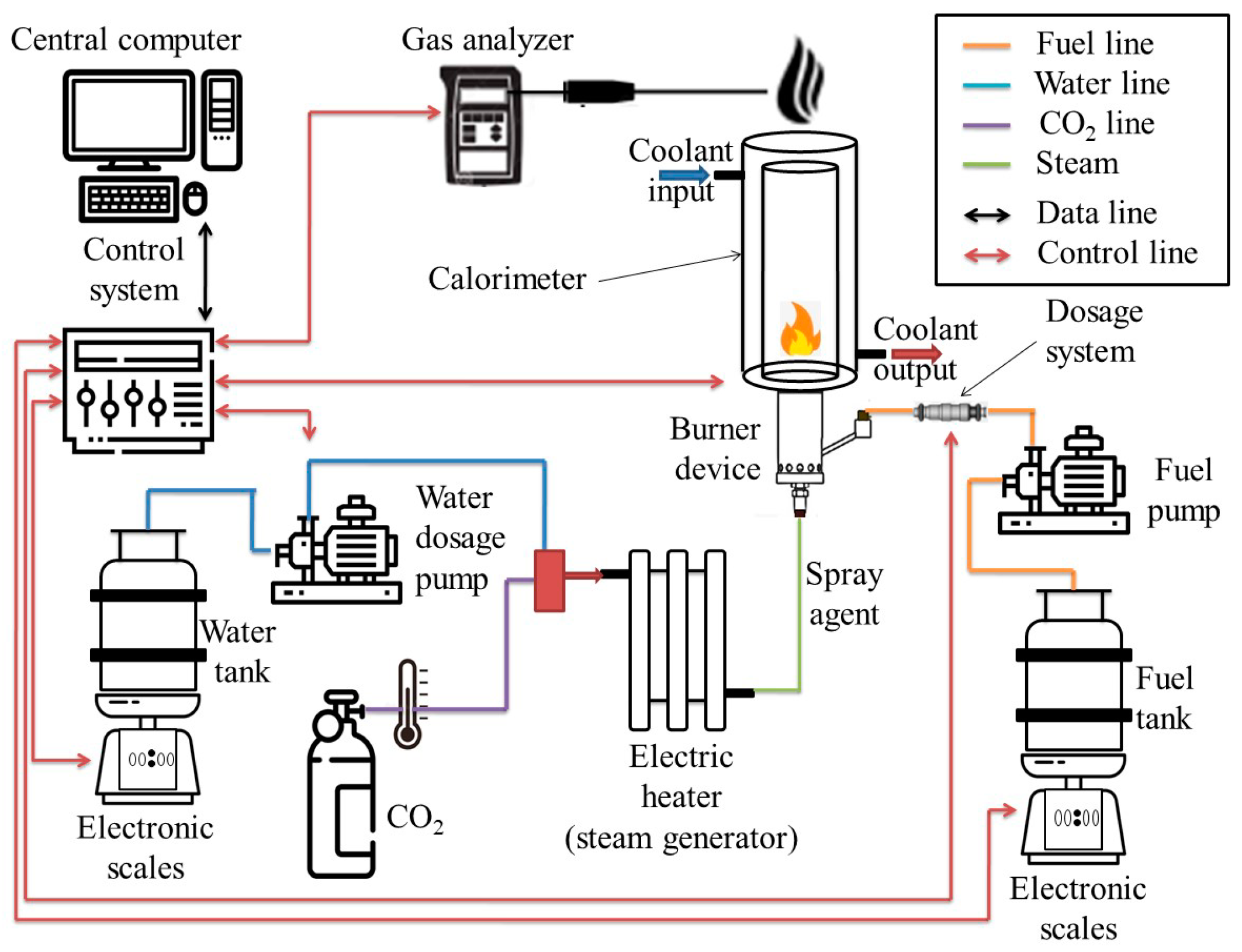
The experiments were carried out on an experimental setup for studying the soot–steam regime of the combustion of liquid hydrocarbons, which is part of the unique scientific installation, USI, “Large-scale thermohydrodynamic stand for the study of thermal and gas-dynamic characteristics of power plants” [54]. The installation consists of a burner, a water supply system, a carbon dioxide supply system, an electric steam generator for superheating steam and heating carbon dioxide to a predetermined temperature, and a liquid fuel supply system (Figure 2). A stable mass fuel flow rate is set by a pump and a fuel injector; to control the fuel flow rate, the fuel tank is mounted on an Acom PC-100W-10H electronic scale. The water flow is set by a plunger dosing pump and is controlled according to data from the Acom PC-100W-10H electronic scales, where a water tank is installed.

2.3. Measurement Methods

To measure the completeness of fuel combustion and the final products of combustion, a flow calorimeter is used, in which flue gases and coolant move in countercurrent. The calorimeter is a tube-in-tube heat exchanger with a total length of 12 m, consisting of five series-connected vertical sections. Each section of the calorimeter consists of 2 coaxial tubes with a wall thickness of 4 mm. Flue gases flow in the inner channel (channel diameter 68 mm), and, in the annular channel (10 mm wide), the coolant (water). Removal of air pockets from the annular channel is provided by automatic valves. In the lower elbows, there are valves for draining condensate from the internal channel, which is formed during the cooling of the combustion products, as well as valves for draining the coolant from the annular channel. Outside, the calorimeter is thermally insulated. For more information, see [55].
During the calorimetric measurements, the burner is placed coaxially with the calorimeter section so that the burner flame is located in the internal channel of the calorimeter. After the establishment of a stationary thermal regime, when the constancy of the coolant temperature at the calorimeter inlet and outlet is achieved, the heat release is measured for 15 min. To do this, a constant water flow is preliminarily set using a control valve, and the water temperature is measured at the inlet and outlet of the calorimeter using chromel alumel thermocouples.
The volumetric flow rate of the coolant (water) is determined using a flow meter with a relative error of 2%. During the experiments, the water flow rate is maintained at a level of about 300 L/h, which ensures that the temperature difference between the coolant at the inlet and outlet of the calorimeter is no more than 50 °C. The volume flow of gases at the outlet of the calorimeter is determined using a RABO G25 rotary counter (measurement error ± 5% of the measured value). The amount of heat obtained from the combustion products in the calorimeter during the experiment, which characterizes the completeness of combustion, is calculated as the difference between the thermal energy of water at the outlet and the inlet to the calorimeter:
Q = Q o u t   Q i n   Q s + Q r + Q g Q o u t = G τ c p o u t ρ o u t t o u t Q i n = G τ c p i n ρ i n t i n Q s = ( h 2 H 2 O h 1 H 2 O ) F v τ + ( h 2 C O 2 h 1 C O 2 ) F C O 2 τ Q r = S ε σ T 4 τ Q g = ( C C O 2 G C O 2 + C N 2 G N 2 ) ( T o u t T a m b ) τ
In this system:
Q is the fuel heat release; Qout is the heat contained in the coolant at the calorimeter outlet; Qin is the heat contained in the coolant at the calorimeter inlet; Qs is the heat introduced with the spraying agent (water vapor and CO2), heated in an external electric steam generator-heater; Qr is the heat loss via radiation from the burner surface; Qg is the heat loss with gases leaving the calorimeter; G is the coolant flow rate (m3/h); τ is the measurement time; C is the coolant heat capacity; ρ is the coolant density (kg/m3); t is the coolant temperature; h is the substance enthalpy (steam and CO2); Fv FCO2 are the steam and CO2 flow rates; S is the burner radiation surface area; ε is the surface emissivity; σ is the Stefan–Boltzmann constant; T is the burner surface temperature; Tout is the temperature of the gases leaving the calorimeter; Tamb is the ambient temperature.
  • tin and tout are coolant (water) temperatures at the entrance and exit of the calorimeter. They are defined as the average throughout the period of measurement in a steady-state thermal regime.
  • Cp = f(t) and ρ = f(t) are the coolant (water) heat capacity and density. They are determined by the average temperature at the inlet and outlet of the calorimeter using thermodynamic tables.
  • h = f(t;p) is the steam and carbon dioxide enthalpy. It is defined as a function of the state of the matter on its parameters using thermodynamic tables.
  • T is the burner surface temperature; it is identified by measurement with a Fluke Ti32 thermal imager.
  • CCO2 and CN2 are the heat capacities of flue gases. They are determined from the thermodynamic tables of substances.
The total error in measuring the heat of fuel combustion in the described calorimeter does not exceed 2.5%.
The gas composition of the final combustion products and at the points inside the flame was measured by gas analyzers “Test-1” and “Testo 350”. Characteristics of the Test-1 gas analyzer: O2 electrochemical sensor (measurement range of 0–25%); H2 polarographic sensor (0–40%); CO2 optical sensor (0–30%); CnHm optical sensor (0–5%); CO electrochemical sensor (0–2000 ppm). Error limits for O2: ±0.2% vol. (absolute); error limits for H2, CO2, CnHm: ±5% (relative); CO: ±2 ppm (absolute, readings of up to 40 ppm) and ±5% (relative, readings of above 40 ppm). Characteristics of the Testo 350 gas analyzer: electrochemical sensors for NO (measurement range of 0–300 ppm) and NO2 (0–500 ppm). Error limits for NO: ±2 ppm (absolute, readings of up to 40 ppm) and ±5% (relative, readings over 40 ppm); NO2: ±5 ppm (absolute, readings of up to 100 ppm) and ±5% (relative, at readings over 100 ppm).
The gas composition of the final combustion products was measured at the outlet of the calorimeter, where the flue gas has a temperature close to room temperature. The gas composition in the flame was analyzed along the vertical axis of the burner from the nozzle to the distance of 200 mm with a step of 20 mm. Samples were taken from the flame through a water-cooled probe to “freeze” the ongoing processes. The combustion products moved along the inner channel of the probe, and the movement of water to cool the sample occurred in the opposite direction along the outer channel. The measurement time at each point is 90 s, the data collection frequency is 1 Hz. For the gas analysis, the sampling probe was fixed on a position device, for which the end of the probe was placed at various points of the flame.
When analyzing the final products of combustion and assessing the value of harmful emissions, the volume concentrations (ppm) were recalculated into specific values (mg/kWh) using the methodological approaches of the DIN EN 267 standard [56], adjusted for the presence of a diluent spray, to compare the data with world analogs:
N O x = N O x ( p p m ) 2.056 ( 21 21 O m e a s ) V 0 + V C O 2 Q l h v
C O = C O ( p p m ) 1.25 ( 21 21 O m e a s ) V 0 + V C O 2 Q l h v
where 2.056 and 1.25 are NOx and CO densities under normal conditions, respectively, kg/m3; NOx(ppm) and COppm are measured contents of relevant compounds in the flue gases, ppm; Omeas is the measured content of oxygen in the flue gases, vol. %; V0 is the theoretical volume of dry air required for complete combustion of 1 kg of fuel, m3/kg (for diesel ~10.46 m3/kg); VCO2 is the volume of carbon dioxide used to spray the fuel; Qlhv is the lower specific calorific value of fuel, kWh/kg (for diesel ~11.86 kWh/kg).
In these formulas, the value of VCO2 reflects the addition of carbon dioxide to the spray jet, which ensures that the volume of combustion products exceeds the theoretical one. The absence of a similar additive for steam is explained by the fact that almost the entire volume of introduced water vapor is condensed by the time it leaves the calorimeter, where the gas composition is analyzed.
It should be noted that the volume of carbon dioxide introduced in the limiting case (regime 5, see Table 1) does not exceed 6% of the theoretical volume of combustion products and that the use of these formulas allows us to avoid underestimating emissions when using a diluent gas and to carry out a correct comparison with the DIN EN 267 standard [56].
The time-averaged temperature in the flame was determined using a Pt-Rh/Pt-Rh thermocouple of type B (diameter of 0.3 mm; relative instrument error of 0.5%). The thermocouple measurement range was 600–1600 °C; in a short time, it was up to 1800 °C. For its location at the desired point of the flame, the thermocouple was fixed on a moving-coordinate device. The measurements were carried out inside the flame along the vertical axis of the burner, with a step of 10 mm up to a distance of 200 mm from the outlet nozzle. The measurement lasted 30 s at each point: first, a delay of 10 s was performed, and then a measurement was made for 20 s at a sampling rate of 10 Hz.
When measuring temperatures with thermocouples, radiation losses are significant (up to 100 °C). Radiation losses from the thermocouple surface in a high-temperature flow were taken into account by the formula for round thermocouples [57]:
Δ T = 1.25 ε σ d 3 4 T c 4 η 1 4 λ ρ V 1 4
where ε is the thermocouple emissivity; σ is the Stefan–Boltzmann constant; d is the thermocouple diameter; Tc is thermal junction temperature; λ, and η are the coefficients of the gas thermal conductivity and viscosity; ρ is the gas density; V is the gas velocity.

2.4. Selection of Operating Parameters

During the experiments, diesel fuel was sprayed with steam, carbon dioxide, or their mixture. To match the regimes to each other, the fuel flow rate was taken to be the same, and the CO2 flow rate (single or in a mixture with water vapor) was selected based on the equality of forces of the spray jet reaction to a drop of fuel. The problem of calculating the spray jet momentum was considered in detail in [58,59]. With the same intensity of the dynamic action of steam, carbon dioxide, or their mixture in selected regimes, the same amount of oxidizer (air) is sucked from the atmosphere through the holes in the lower part of the burner body. An equal inflow of external air provides similar values of the integral excess air ratio, which makes it legitimate to compare the regimes, whose parameters are presented in Table 1. The properties of diesel fuel are shown in Table 2.

3. Results and Discussion

The time-averaged temperature profiles along the flame symmetry axis were obtained for the selected parameters of steam, CO2, and their mixture (see Table 1) (Figure 3).
The measurement of temperatures along the symmetry axis of the flame shows the closeness of the values along the entire length of the flame for all the considered regimes. In this case, the temperature maximum is reached at a certain distance from the burner nozzle, which indicates fuel burnout in the external flame and corresponds to the nature of the combustion of the diffusion flame.
On the right side of Figure 3, we can see that the difference in the temperature maximum (indicated in the figure as ∆) for all the regimes does not exceed 50 degrees and is in the region of 1750 °C. This can be explained by the similar effect of increasing the mixture heat capacity when a jet of steam or carbon dioxide is added. Although CO2 has a lower heat capacity (~1.9 times) than steam, it is supplied in a larger amount (~1.63 times when comparing regimes 1 and 5); as a result, a similar effect of diluting the combustible mixture is achieved.
The similarity of the temperature profiles of the flame indicates the same flame length. Despite this, the color of the flame when burning diesel in a jet of water vapor or carbon dioxide is noticeably different. Combustion in the presence of water vapor is characterized by a bluish glow at the base of the flame, which gradually changes to orange tails at its end. As the steam in the atomizer jet is replaced with carbon dioxide, the bluish area at the base reduces, and the color of the flame changes along its entire length towards orange hues. The different glow may be due to the difference in the composition of the gaseous components of the flame. Photographs of the flame for the various modes are shown in Figure 4.
It is easy to see from Figure 4 that the same flame length is observed for all the modes, which corresponds to the thermocouple measurements. Next, the gas components are analyzed along the vertical axis of the flame, and the final combustion products are measured.
Table 3 presents the results of the gas analysis of the final products of the diesel fuel combustion, cooled to room temperature, at the calorimeter outlet.
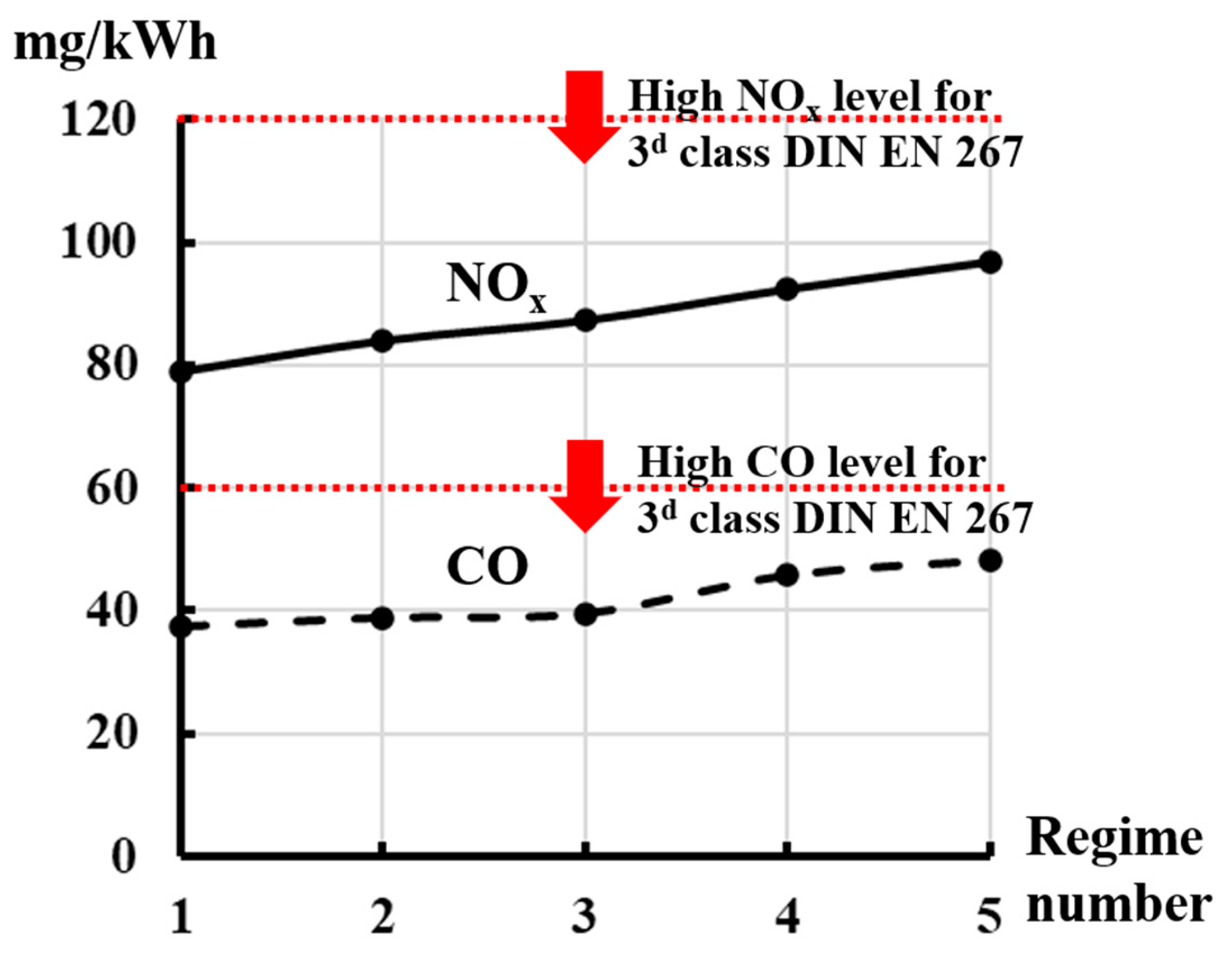
It can be noted that with the gradual replacement of steam with carbon dioxide (moving from regime 1 to regime 5), the concentration of oxygen in the combustion products decreases, and the proportion of carbon dioxide increases. Since the fuel flow rate is constant, and the suction of atmospheric air into the burner, caused by the ejection of the spray jet, is the same in all the regimes due to the momentum equality, this is explained by the introduction of the additional volume of CO2 as it replaces the steam. The concentrations of CO and NOx in the flue gases increase slowly as the steam is replaced with carbon dioxide. However, the volume of exhaust gases changes also. Therefore, it is advisable to recalculate the volumetric concentrations of NOx and CO, determined by the gas analyzer [ppm], into specific emissions [mg/kWh] to be able to compare the obtained parameters with regulatory documents and world analogs. To do this, Formulas (1) and (2), presented in the section on measurement methods, are used. The calculation results are presented graphically (Figure 5).
The pollutant emission rates converted to specific values show an increase as the transition from steam-spraying to carbon dioxide-spraying occurs. The growth is approximately 25% for each of the studied components. This can be assumed to relate to the chemical effect of the presence of steam affecting the course of chemical reactions since the physical effect of diluting the combustible mixture is similar for all the mixture options, which was noted when analyzing the temperature profile. Nevertheless, all the investigated regimes of the burner operation correspond with a margin to the most stringent DIN EN 267 standard [56].
When analyzing the completeness of fuel combustion, it was found that, in all cases, its value exceeds 98% and is in a narrow range of 45.14–46 MJ/kg, which is close to the HHV of diesel (46 MJ/kg). At the same time, no obvious dependence of fuel combustion completeness on the composition of the sprayer was noted.
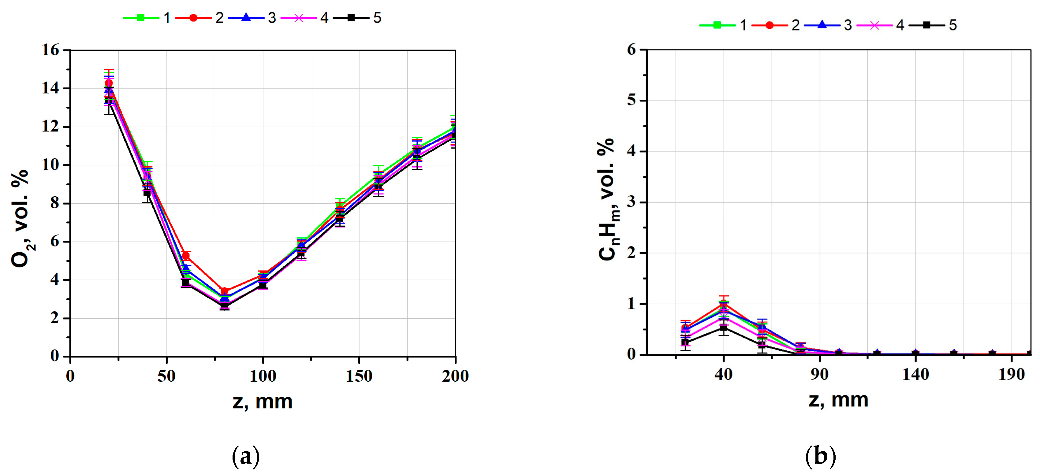
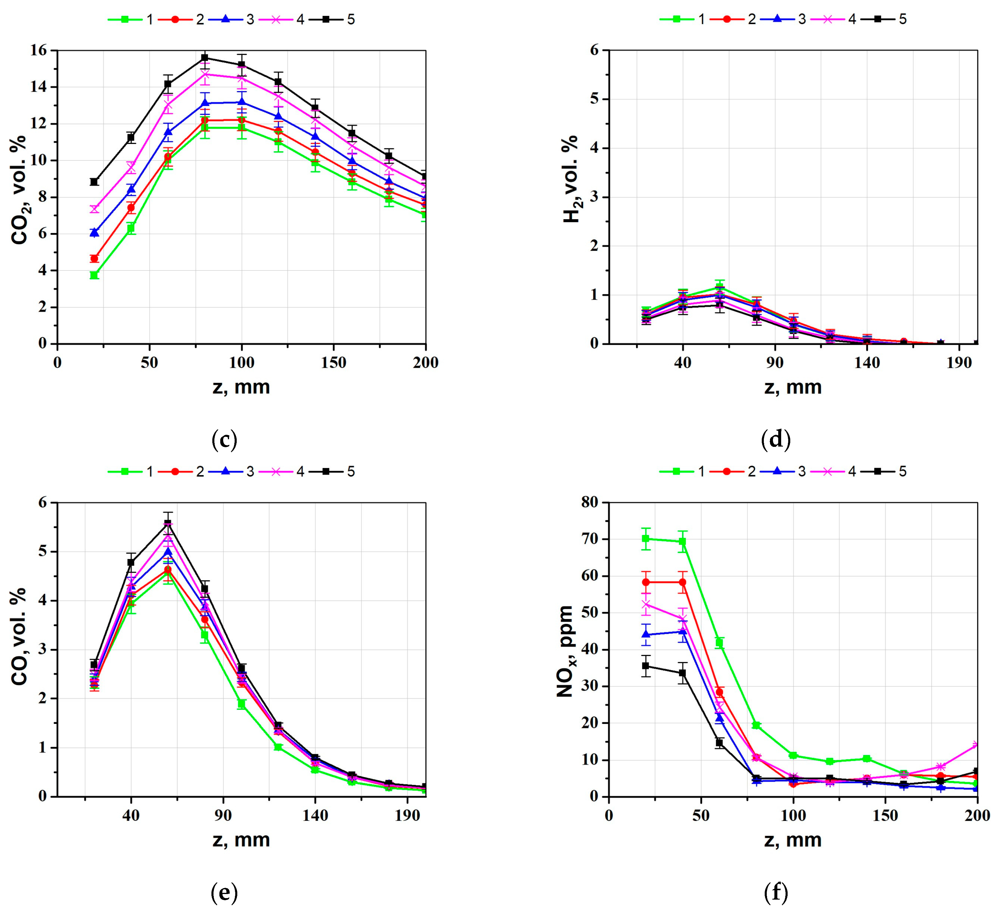
The results of the analysis of the gaseous components of the flame along its vertical axis are shown in Figure 6.
For the regimes under study, the profiles of corresponding intermediate components have a similar shape. The content of O2 in the flame is at its minimum (~3 vol. %) in the region of the maximum temperatures. Further upstream, the oxygen concentration increases, while concentrations of the remaining components decrease due to the dilution of the flame with air coming from the environment.
The maximum value of the CO2 content in the flame increases when the steam is replaced with carbon dioxide. The difference in values for the extreme regimes (11.8 vol. %—regime 1; 15.6 vol. %—regime 5) corresponds to the additional amount of carbon dioxide introduced with the sprayer. The CO concentration is at its maximum at a distance of ~60 mm from the burner nozzle and decreases with an increase in the proportion of steam in the sprayer (5.6 vol. %—5 regime; 4.6 vol. %—1 regime), which may be due to the presence of OH radicals in the combustion zone and more intense oxidation of CO to CO2. Such a decrease in CO concentration is also observed for the final products of combustion, which was noted earlier. In addition, for the regimes with high steam injection, a slight increase in H2 concentration in the flame (up to 0.4 vol. %) is observed, which is explained by steam gasification with the formation of synthesis gas (H2O + C → CO + H2). The content of nitrogen oxides in the flame decreases with the distance from the burner nozzle, due to the dilution of the flame with air from the environment and a decrease in the flame temperature (longer than 60 mm). At the same time, at a distance of 200 mm from the burner nozzle, the NOx concentration is lower for those regimes where the proportion of steam in the atomizer jet is higher. A similar dependence is also observed for the final products of combustion.

4. Conclusions

In this work, the combustion characteristics of liquid hydrocarbons are studied using the example of diesel fuel in the presence of a mixture of superheated steam with carbon dioxide (SCIM), pure CO2 (CIM), or superheated steam (SIM) in a spray burner. The paper compares the characteristics obtained and shows the possibility of complete or partial replacement of superheated steam and the advantages of steam in terms of reducing harmful emissions. The parameters of the supplied gas mixture were chosen based on the equality of the intensities of the dynamic effects of the flame on the fuel drop.
It has been found that the flame temperature along the vertical axis of the burner nozzle does not change when switching from steam-spraying to carbon dioxide. For all the studied regimes, high completeness of fuel combustion is observed.
The analysis of the composition of final combustion products shows that when steam is replaced with carbon dioxide, concentrations of the toxic combustion products CO and NOx increase by 25%. This can be assumed to relate to the chemical effect of the presence of steam affecting the course of chemical reactions since the physical effect of diluting the combustible mixture is similar for all the mixture options. However, all the investigated regimes of burner operation comply with the most stringent DIN EN 267 standard [56].
It was found that the minimums of O2 and the maximums of CO, CO2, CnHm, and H2 for the studied regimes were observed at the same distance from the burner nozzle; the profiles of the corresponding components have a similar shape. In this case, the values of H2 and CnHm in the flame are higher, and the values of CO and CO2 are lower when the proportion of steam in the spray jet is greater, which indicates the differences in the reactions occurring in the flame.
The results obtained show that it is possible to replace partially or completely superheated steam with carbon dioxide to burn liquid combustible waste, but with a certain increase in the content of harmful emissions.
The experimental data obtained will be used to verify numerical models aimed at designing pilot industrial samples of burners for waste-to-energy.

Author Contributions

Conceptualization, S.A.; data curation, E.K.; funding acquisition, O.S.; methodology, E.K.; project administration, O.S.; supervision, S.A.; formal analysis, M.M.; investigation, I.S.; writing—original draft preparation, I.S., M.M. and E.K.; writing—review and editing, I.S., E.K. and O.S. All authors have read and agreed to the published version of the manuscript.

Funding

The work was financially supported by the Ministry of Science and Higher Education of the Russian Federation, Agreement of 29 September 2020 No. 075-15-2020-806.

Data Availability Statement

The data presented in this study are available upon request from the authors.

Conflicts of Interest

The authors declare no conflict of interest.

Nomenclature

CIMcarbon dioxide injection method
HHVhigher heating value
LHVlower heating value
SCIMsuperheated steam and carbon dioxide injection method
SIMsuperheated steam injection method
FCO2mass flow rate of CO2, kg/s
Fvmass flow rate of water vapor, kg/s
Gcoolant flow rate, m3/h
hspecific enthalpy, J/kg
NOx(ppm)measured content of nitrogen oxides in flue gases, ppm
Omeasmeasured content of oxygen in flue gases, vol. %
Qheat release, J
Qgheat loss with gases leaving the calorimeter, J
Qinheat in the coolant at the calorimeter inlet, J
Qlhvlower specific calorific value of fuel, kWh/kg
Qoutheat in the coolant at the calorimeter outlet, J
Qrheat loss via radiation from the burner surface, J
Qsheat introduced with spraying agent, J
Sradiant surface area of the burner, m2
Tburner surface temperature, K
tcoolant temperature, K
Tambambient temperature, K
Tcthermal junction temperature, K
tincoolant temperature at the calorimeter inlet, K
toutcoolant temperature at the calorimeter outlet, K
Touttemperature of gases leaving the calorimeter, K
Vgas velocity, m/s
V0theoretical volume of dry air required for complete combustion of 1 kg of fuel, m3/kg
VCO2the volume of carbon dioxide used to spray the fuel, m3/kg
εemissivity
ηgas viscosity coefficient, Pa·s
λgas heat conductivity coefficient, W/m·K
ρdensity, kg/m3
σStefan-Boltzmann constant, kg/s3K4
τmeasurement time, s

References

  1. World Energy Outlook 2022—Analysis—IEA. Available online: https://www.iea.org/reports/world-energy-outlook-2022 (accessed on 4 April 2023).
  2. Pathways to Net Zero: The Impact of Clean Energy Research. Available online: https://www.iea.org/reports/net-zero-by-2050 (accessed on 8 February 2023).
  3. World Energy & Climate Statistics—Yearbook. 2021. Available online: https://yearbook.enerdata.net/ (accessed on 26 April 2023).
  4. James, B. Cost and Performance Baseline for Fossil Energy Plants Volume 1: Bituminous Coal and Natural Gas to Electricity; DOE/NETL-2010/1397; National Energy Technology Laboratory: Albany, OR, USA, 2010.
  5. Wang, T.; Stiegel, G. Integrated Gasification Combined Cycle (IGCC) Technologies, 1st ed.; Elsevier: Amsterdam, The Netherlands, 2016; ISBN 9780081001851. [Google Scholar] [CrossRef]
  6. Lam, S.S.; Liew, R.K.; Jusoh, A.; Chong, C.T.; Ani, F.N.; Chase, H.A. Progress in waste oil to sustainable energy, with emphasis on pyrolysis techniques. Renew. Sustain. Energy Rev. 2016, 53, 741–753. [Google Scholar] [CrossRef]
  7. Ramirez, D.; Collins, C.D. Maximisation of oil recovery from an oil-water separator sludge: Influence of type, concentration, and application ratio of surfactants. Waste Manag. 2018, 82, 100–110. [Google Scholar] [CrossRef] [PubMed]
  8. Solid Waste Management. Available online: https://www.worldbank.org/en/topic/urbandevelopment/brief/solid-waste-management (accessed on 21 September 2022).
  9. Bosmans, A.; Vanderreydt, I.; Geysen, D.; Helsen, L. The crucial role of Waste-to-Energy technologies in enhanced landfill mining: A technology review. J. Clean. Prod. 2013, 55, 10–23. [Google Scholar] [CrossRef] [Green Version]
  10. Breeze, P. Energy from Waste; Elsevier: Amsterdam, The Netherlands, 2018; ISBN 9780081010426. [Google Scholar] [CrossRef]
  11. Rogoff, M.J.; Screve, F. Waste-to-Energy; Elsevier: Amsterdam, The Netherlands, 2019; ISBN 9780128160794. [Google Scholar] [CrossRef]
  12. Malekli, M.; Aslani, A.; Zolfaghari, Z.; Zahedi, R.; Moshari, A. Advanced bibliometric analysis on the development of natural gas combined cycle power plant with CO2 capture and storage technology. Sustain. Energy Technol. Assess. 2022, 52, 102339. [Google Scholar] [CrossRef]
  13. Lu, X.; Han, D.; Huang, Z. Fuel design and management for the control of advanced compression-ignition combustion modes. Prog. Energy Combust. Sci. 2011, 37, 741–783. [Google Scholar] [CrossRef]
  14. Kook, S.; Bae, C.; Miles, P.C.; Choi, D.; Pickett, L.M. The Influence of Charge Dilution and Injection Timing on Low-Temperature Diesel Combustion and Emissions; SAE Technical Papers; SAE International: Warrendale, PA, USA, 2005. [Google Scholar] [CrossRef] [Green Version]
  15. Yao, M.; Zheng, Z.; Liu, H. Progress and recent trends in homogeneous charge compression ignition (HCCI) engines. Prog. Energy Combust. Sci. 2009, 35, 398–437. [Google Scholar] [CrossRef]
  16. Hachem, J.; Schuhler, T.; Orhon, D.; Cuif-Sjostrand, M.; Zoughaib, A.; Molière, M. Exhaust gas recirculation applied to single-shaft gas turbines: An energy and exergy approach. Energy 2022, 238, 121656. [Google Scholar] [CrossRef]
  17. Climent, H.; Dolz, V.; Pla, B.; González-Domínguez, D. Analysis on the potential of EGR strategy to reduce fuel consumption in hybrid powertrains based on advanced gasoline engines under simulated driving cycle conditions. Energy Convers. Manag. 2022, 266, 115830. [Google Scholar] [CrossRef]
  18. Takaki, D.; Tsuchida, H.; Kobara, T.; Akagi, M.; Tsuyuki, T.; Nagamine, M. Study of an EGR System for Downsizing Turbocharged Gasoline Engine to Improve Fuel Economy; SAE Technical Papers; SAE International: Warrendale, PA, USA, 2014; Volume 1. [Google Scholar] [CrossRef]
  19. Liu, H.; Zhang, L.; Li, Q.; Zhu, H.; Deng, L.; Liu, Y.; Che, D. Effect of FGR position on the characteristics of combustion, emission and flue gas temperature deviation in a 1000 MW tower-type double-reheat boiler with deep-air-staging. Fuel 2019, 246, 285–294. [Google Scholar] [CrossRef]
  20. Yan, J.; Zheng, X.; Lu, X.; Liu, Z.; Fan, X. Enhanced combustion behavior and NOx reduction performance in a CFB combustor by combining flue gas recirculation with air-staging: Effect of injection position. J. Energy Inst. 2021, 96, 294–309. [Google Scholar] [CrossRef]
  21. Zhang, P.; Shao, Y.; Niu, J.; Zeng, X.; Zheng, X.; Wu, C. Effect of low-nitrogen combustion system with flue gas circulation technology on the performance of NOx emission in waste-to-energy power plant. Chem. Eng. Process.—Process Intensif. 2022, 175, 108910. [Google Scholar] [CrossRef]
  22. Warnatz, J.; Maas, U.; Dibble, R.W. Combustion; Springer: Berlin/Heidelberg, Germany, 2006; ISBN 978-3-540-25992-3. [Google Scholar] [CrossRef]
  23. Kobayashi, H.; Hagiwara, H.; Kaneko, H.; Ogami, Y. Effects of CO2 dilution on turbulent premixed flames at high pressure and high temperature. Proc. Combust. Inst. 2007, 31, 1451–1458. [Google Scholar] [CrossRef]
  24. Li, A.; Zheng, Z.; Peng, T. Effect of water injection on the knock, combustion, and emissions of a direct injection gasoline engine. Fuel 2020, 268, 117376. [Google Scholar] [CrossRef]
  25. Lee, M.C.; Seo, S.B.; Yoon, J.; Kim, M.; Yoon, Y. Experimental study on the effect of N2, CO2, and steam dilution on the combustion performance of H2 and CO synthetic gas in an industrial gas turbine. Fuel 2012, 102, 431–438. [Google Scholar] [CrossRef]
  26. Le Cong, T.; Dagaut, P. Experimental and Detailed Modeling Study of the Effect of Water Vapor on the Kinetics of Combustion of Hydrogen and Natural Gas, Impact on NOx. Energy Fuels 2009, 23, 725–734. [Google Scholar] [CrossRef]
  27. Albin, E.; Nawroth, H.; Göke, S.; D’Angelo, Y.; Paschereit, C.O. Experimental investigation of burning velocities of ultra-wet methane-air-steam mixtures. Fuel Process. Technol. 2013, 107, 27–35. [Google Scholar] [CrossRef] [Green Version]
  28. Zou, C.; Song, Y.; Li, G.; Cao, S.; He, Y.; Zheng, C. The chemical mechanism of steam’s effect on the temperature in methane oxy-steam combustion. Int. J. Heat Mass Transf. 2014, 75, 12–18. [Google Scholar] [CrossRef]
  29. Honzawa, T.; Kai, R.; Seino, M.; Nishiie, T.; Suzuki, Y.; Okada, A.; Wazaki, K.; Kurose, R. Numerical and experimental investigations on turbulent combustion fields generated by large-scale submerged combustion vaporizer burners with water spray equipment. J. Nat. Gas Sci. Eng. 2020, 76, 103158. [Google Scholar] [CrossRef]
  30. Cui, G.; Dong, Z.; Wang, S.; Xing, X.; Shan, T.; Li, Z. Effect of the water on the flame characteristics of methane hydrate combustion. Appl. Energy 2020, 259, 114205. [Google Scholar] [CrossRef]
  31. Donohoe, N.; Heufer, K.A.; Aul, C.J.; Petersen, E.L.; Bourque, G.; Gordon, R.; Curran, H.J. Influence of steam dilution on the ignition of hydrogen, syngas and natural gas blends at elevated pressures. Combust. Flame 2015, 162, 1126–1135. [Google Scholar] [CrossRef] [Green Version]
  32. Allam, R.; Martin, S.; Forrest, B.; Fetvedt, J.; Lu, X.; Freed, D.; Brown, G.W.; Sasaki, T.; Itoh, M.; Manning, J. Demonstration of the Allam Cycle: An Update on the Development Status of a High Efficiency Supercritical Carbon Dioxide Power Process Employing Full Carbon Capture. Energy Procedia 2017, 114, 5948–5966. [Google Scholar] [CrossRef]
  33. Datsenko, V.V.; Zeigarnik, Y.A.; Kalashnikova, E.O.; Kosoy, A.A.; Kosoy, A.S.; Sinkevich, M.V. Combined cycle plants with complete capturing of carbon dioxide for clean power projects. Thermophys. Aeromech. 2021, 27, 775–781. [Google Scholar] [CrossRef]
  34. Gutiérrez, F.A.; García-Cuevas, L.M.; Sanz, W. Comparison of cryogenic and membrane oxygen production implemented in the Graz cycle. Energy Convers. Manag. 2022, 271, 116325. [Google Scholar] [CrossRef]
  35. Alekseenko, S.V.; Shchinnikov, P.A.; Sadkin, I.S. Effect of thermodynamic parameters on energy characteristics of CO2 power cycles during oxygen combustion of methane. Thermophys. Aeromech. 2023, 30, 83–92. [Google Scholar] [CrossRef]
  36. Crespi, F.; Gavagnin, G.; Sánchez, D.; Martínez, G.S. Supercritical carbon dioxide cycles for power generation: A review. Appl. Energy 2017, 195, 152–183. [Google Scholar] [CrossRef]
  37. Darabkhani, H.G.; Varasteh, H.; Bazooyar, B. Oxyturbine power cycles and gas-CCS technologies. In Carbon Capture Technologies for Gas-Turbine-Based Power Plants; Elsevier: Amsterdam, The Netherlands, 2023; pp. 39–74. ISBN 978-0-12-818868-2. [Google Scholar] [CrossRef]
  38. Kobayashi, H.; Yata, S.; Ichikawa, Y.; Ogami, Y. Dilution effects of superheated water vapor on turbulent premixed flames at high pressure and high temperature. Proc. Combust. Inst. 2009, 32, 2607–2614. [Google Scholar] [CrossRef]
  39. Xie, Y.; Wang, J.; Xu, N.; Yu, S.; Huang, Z. Comparative study on the effect of CO2 and H2O dilution on laminar burning characteristics of CO/H2/air mixtures. Int. J. Hydrog. Energy 2014, 39, 3450–3458. [Google Scholar] [CrossRef]
  40. Wang, Z.H.; Weng, W.B.; He, Y.; Li, Z.S.; Cen, K.F. Effect of H2/CO ratio and N2/CO2 dilution rate on laminar burning velocity of syngas investigated by direct measurement and simulation. Fuel 2015, 141, 285–292. [Google Scholar] [CrossRef]
  41. Weng, W.B.; Wang, Z.H.; He, Y.; Whiddon, R.; Zhou, Y.J.; Li, Z.S.; Cen, K.F. Effect of N2/CO2 dilution on laminar burning velocity of H2–CO–O2 oxy-fuel premixed flame. Int. J. Hydrog. Energy 2015, 40, 1203–1211. [Google Scholar] [CrossRef]
  42. Vu, T.M.; Park, J.; Kwon, O.B.; Bae, D.S.; Yun, J.H.; Keel, S.I. Effects of diluents on cellular instabilities in outwardly propagating spherical syngas–air premixed flames. Int. J. Hydrog. Energy 2010, 35, 3868–3880. [Google Scholar] [CrossRef]
  43. Liu, F.; Karataş, A.E.; Gülder, Ö.L.; Gu, M. Numerical and experimental study of the influence of CO2 and N2 dilution on soot formation in laminar coflow C2H4/air diffusion flames at pressures between 5 and 20 atm. Combust. Flame 2015, 162, 2231–2247. [Google Scholar] [CrossRef] [Green Version]
  44. Giurcan, V.; Razus, D.; Mitu, M.; Oancea, D. Prediction of flammability limits of fuel-air and fuel-air-inert mixtures from explosivity parameters in closed vessels. J. Loss Prev. Process Ind. 2015, 34, 65–71. [Google Scholar] [CrossRef]
  45. Tran, M.V.; Scribano, G.; Chong, C.T.; Ng, J.H.; Ho, T.X. Numerical and experimental study of the influence of CO2 dilution on burning characteristics of syngas/air flame. J. Energy Inst. 2019, 92, 1379–1387. [Google Scholar] [CrossRef]
  46. Vigriyanov, M.S.; Anufriev, I.S.; Kopyev, E.P.; Sharypov, O.V.; Shadrin, E.Y. Burner device 2018.
  47. Anufriev, I.S.; Kopyev, E.P.; Sadkin, I.S.; Mukhina, M.A. Diesel and waste oil combustion in a new steam burner with low NOX emission. Fuel 2021, 290, 120100. [Google Scholar] [CrossRef]
  48. Anufriev, I.S.; Kopyev, E.P.; Sadkin, I.S.; Mukhina, M.A. NOx reduction by steam injection method during liquid fuel and waste burning. Process Saf. Environ. Prot. 2021, 152, 240–248. [Google Scholar] [CrossRef]
  49. Anufriev, I.S.; Shadrin, E.Y.; Kopyev, E.P.; Alekseenko, S.V.; Sharypov, O.V. Study of liquid hydrocarbons atomization by supersonic air or steam jet. Appl. Therm. Eng. 2019, 163, 114400. [Google Scholar] [CrossRef]
  50. Sadkin, I.S.; Kopyev, E.P.; Mukhina, M.A.; Anufriev, I.S. Experimental study of the characteristics of heptane combustion in a high-speed steam jet. J. Phys. Conf. Ser. 2022, 2233, 012001. [Google Scholar] [CrossRef]
  51. Alekseenko, S.V.V.; Anufriev, I.S.S.; Vigriyanov, M.S.S.; Kopyev, E.P.P.; Sadkin, I.S.S.; Sharypov, O.V. Burning of Heavy Fuel Oil in a Steam Jet in a New Burner. J. Appl. Mech. Tech. Phys. 2020, 61, 324–330. [Google Scholar] [CrossRef]
  52. Anufriev, I.; Kovyev, E.; Alekseenko, S.S.; Sharypov, O.; Butakov, E.; Vigriyanov, M.; Sadkin, I. Cleaner crude oil combustion during superheated steam atomization. Therm. Sci. 2021, 25, 331–345. [Google Scholar] [CrossRef]
  53. Anufriev, I.S.; Kopyev, E.P.; Alekseenko, S.V.; Sharypov, O.V.; Vigriyanov, M.S. New ecology safe waste-to-energy technology of liquid fuel combustion with superheated steam. Energy 2022, 250, 123849. [Google Scholar] [CrossRef]
  54. Unique Research Facility USU “Large-Scale Thermo-Hydrodynamic Setup for Studying the Thermal and Gas-Dynamic Characteristics of Power Plants”. Available online: http://ckp-rf.ru/usu/73570/ (accessed on 19 April 2023).
  55. Anufriev, I.S.; Kopyev, E.P. Diesel fuel combustion by spraying in a superheated steam jet. Fuel Process. Technol. 2019, 192, 154–169. [Google Scholar] [CrossRef]
  56. DIN EN 267:2011-11; Automatic Forced Draught Burners for Liquid Fuels. NORMSERVIS: Hamry nad Sázavou, Czech Republic, 2011.
  57. Kaskan, W.E. The dependence of flame temperature on mass burning velocity. Symp. Combust. 1957, 6, 134–143. [Google Scholar] [CrossRef]
  58. Anufriev, I.S.; Krasinsky, D.V.; Shadrin, E.Y.; Kopyev, E.P.; Sharypov, O.V. Investigation of the structure of the gas flow from the nozzle of a spray-type burner. Thermophys. Aeromech. 2019, 26, 657–672. [Google Scholar] [CrossRef]
  59. Kopyev, E.P.; Shadrin, E.Y.; Sadkin, I.S.; Mukhina, M.A.; Shimchenko, S.Y. Experimental Study of Combustion of Liquid Hydrocarbons under the Conditions of Steam Gasification in the Presence of a Diluent Gas. Combust. Explos. Shock Waves 2022, 58, 457–463. [Google Scholar] [CrossRef]
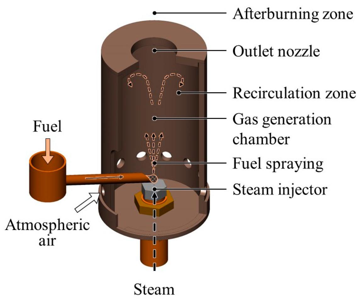
Figure 1. Spray burner.
Energies 16 05745 g001
Figure 2. The scheme of the experimental setup.
Energies 16 05745 g002
Figure 3. Temperature measurement along the axis of flame symmetry (in the center of the burner outlet nozzle) in the experimental range (a), and selected region of the maximum temperature area (b). Each regime is illustrated by its type of curve (regime labels correspond to Table 1).
Energies 16 05745 g003
Figure 4. Photographs of the flame (labels correspond to Table 1).
Energies 16 05745 g004
Figure 5. Emissions of CO and NOx vs. burner operating regime (regime labels correspond to Table 1).
Energies 16 05745 g005
Figure 6. Profiles of intermediate combustion components in the flame along the vertical axis of the burner nozzle (regime labels correspond to Table 1): O2 (a), CnHm (b), CO2 (c), H2 (d), CO (e), NOx (f).
Energies 16 05745 g006aEnergies 16 05745 g006b
Table 1. Description of the regimes under study.
Regime NumberFuel Flow Rate, kg/hSteam Flow Rate, kg/hCO2 Flow Rate, kg/hCO2 Mass Content in the Spray Mixture, %Jet Momentum [57], NTemperature of Steam/CO2/Mixture, °C
11.20.8000.203250
20.60.3436.20.207
30.40.6461.520.206
40.20.9582.610.205
501.31000.207
Table 2. Diesel fuel characteristics.
Properties:Density, kg/m3Viscosity, cStC, %H, %S, %N, %HHV/LHV, MJ/kg
Value:8404.184.613.60.40.642.3/44.9
Table 3. Characteristics of diesel combustion products at the calorimeter outlet, depending on the studied regime.
Regime NumberO2, %CO2, %CO, ppmNOx, ppmQ, MJ/kg
14.0613.29273545.14
23.8514.32293846
33.6515.3304045.87
43.416.36354345.39
53.1917.48374545.61
Disclaimer/Publisher’s Note: The statements, opinions and data contained in all publications are solely those of the individual author(s) and contributor(s) and not of MDPI and/or the editor(s). MDPI and/or the editor(s) disclaim responsibility for any injury to people or property resulting from any ideas, methods, instructions or products referred to in the content.