Article

Load Frequency Control Using the Particle Swarm Optimisation Algorithm and PID Controller for Effective Monitoring of Transmission Line

by
Vincent N. Ogar
,
Sajjad Hussain
and
Kelum A. A. Gamage
*,†
Department of Electrical and Electronic Engineering, James Watt School of Engineering, University of Glasgow, Glasgow G12 8QQ, UK
*
Author to whom correspondence should be addressed.
These authors played the supervisory role.
Energies 2023, 16(15), 5748; https://doi.org/10.3390/en16155748
Submission received: 21 June 2023 / Revised: 6 July 2023 / Accepted: 31 July 2023 / Published: 1 August 2023

Abstract

:
Load frequency control (LFC) plays a critical role in maintaining the stability and reliability of the power system. With the increasing integration of renewable energy sources and the growth of complex interconnected grids, efficient and robust LFC strategies are in high demand. In recent years, the combination of particle swarm optimisation (PSO) and proportional-integral-derivative (PID) controllers, known as PSP-PID, has been used as a promising approach to enhance the performance of LFC systems. This article focuses on modelling, simulation, optimisation, advanced control techniques, expert knowledge, and iterative refinement of the power system to help achieve suitable PID settings that provide reliable control of the load frequency in the transmission line. The performance indices of the proposed algorithm are measured by the integral time absolute error (ITAE), which is 0.0005757 with 0.9994 K i , 0.7741 K p , and 0.1850 K d . The model system dynamics are tested by varying the load frequency from 300 MW to 350 MW at a load variation of 0.2. The suggested controller algorithm is relatively reliable and accurate in power system management and protection load frequency control compared to conventional methods. This work can be improved by including more generating stations synchronised into a single network.

1. Introduction

Load frequency control (LFC) is used in electric power systems to maintain a comparatively consistent frequency, distribute the load among the generators, and manage tie-line exchange schedules. The power system desperately needs load frequency control because the transmitting frequency must correspond to the generating and load frequency, which must synchronise to prevent faults on the transmission line. If the typical frequency is 50 Hz or 60 Hz and the system frequency drops below 47.5 Hz or rises over 52.5 Hz on a 50 Hz frequency band, the turbine blades will likely be harmed, and the generator may stall [1]. The two main variables that vary when there is a transient power demand are area frequency and tie-line power exchange [2].
The primary objective of LFC is to keep the power system’s frequency constant by adjusting the power generation to match the power consumption. The LCF system consists of the primary and the secondary control. The primary control is responsible for quick response to sudden changes in power consumption by adjusting the power generation to match it. It operates on a time scale of seconds. It is typically implemented using governors on power generators. At the same time, the secondary control is responsible for maintaining the balance between power generation and consumption over a longer time scale of minutes to hours. It is typically implemented using automatic generation control (AGC), which adjusts the power output of generators to meet the load demand [3,4]. The LFC system can also be implemented using advanced control methods such as model predictive control (MPC) and artificial intelligence-based methods [5].
A modest variation in load power in a single-area power system that runs at a fixed frequency results in an imbalance of power between supply and demand. The first solution to this mismatch issue is removing kinetic energy from the system, which leads to a decline in system frequency. The old load’s power consumption reduces as the frequency steadily drops. When the newly added load is diverted by lowering the power required by the old load and power linked to kinetic energy is eliminated, substantial power systems may achieve equilibrium at a single point. Without a doubt, a balance is reached at the expense of frequency decrease. To maintain this balance, the system takes some control action; governor activity is unnecessary. In such a situation, the frequency is significantly reduced.
The critical component of a power system that ensures continuous power delivery to the customer is load frequency control. Automatic generation control (AGC) technically accomplishes power system frequency control. To maintain sensible load and generation balance, frequency control splits the load across generators and adjusts the tie-line power to predetermined levels [1].
Different literature has discussed the LFC in transmission lines using conventional methods to stabilise the load frequency of the power system. In [6], the authors suggest a novel PSO-based multi-stage fuzzy controller for solving the LFC issue in a restructured power system. This control technique was adopted because of power systems’ rising complexity and changing structure. This newly developed control strategy combines the fuzzy PD and integral controllers with a fuzzy switch to achieve the desired level of robust performance, including frequency regulation, load demand tracking, and disturbance attenuation. These occur under load fluctuation for various plant parameter changes and system nonlinearities.
A PSO-based method automatically modifies membership functions to save design effort and improve fuzzy system control. The PSO method suggested in this study is simple to implement and requires no extra processing complexity. Experimenting with this approach yields reasonably promising results. There is the capacity to avoid the local optima, and convergence accuracy and speed are significantly improved, resulting in high precision and efficiency. However, the settling time and the overshoot are high, reducing the controller’s performance.
In [7], a hybrid generation system is described, consisting of solar photovoltaic, wind turbine generators, a geothermal power plant, and electric vehicle aggregators to improve the stability of the system by implying the genetic algorithm (GA) and the PID controller to reduce the settling time and overshoot.
Large frequency oscillations occur when the load frequency controller (LFC) system does not correct the imbalanced power [8]. To that purpose, an artificial neural network (ANN) based on particle swarm optimisation (PSO) is proposed to modify the settings of the PID controller in the MG structure. The simulation results show that using PSO-based ANN makes the system stable in the minimum amount of time. Also, the amplitude of frequency oscillations, overshoot, and settling time is minimised. These error values determine the area control error input signal to the PID controller unit, the primary purpose of which is to minimise the error at the output. As a consequence of the preceding explanation, the PSO methodology produces much better results than the fuzzy and trial techniques because the fuzzy approach takes a long time to execute many linguistic rules in a multi-area system simultaneously. Second, obtaining the suitable language rule matrix to achieve the required outcomes is time-consuming. A high number of iterations is necessary to get ideal values of PID gains via a trial technique [9].
In [10], the authors advocate improving load frequency management using a PID controller and a static synchronous series compensator (SSSC). Particle swarm optimisation (PSO) determines the optimal parameters for the PID controller. Though it was only used for one area of LFC, it is limited to specific algorithms. In addition, Ref. [11] suggested an optimisation approach that combines the best aspects of three optimisation techniques—the firefly algorithm (FA), particle swarm optimisation (PSO), and the gravity search algorithm (GSA)—to accomplish automated load frequency management of the multi-source power system; the suggested technique was employed to set the parameters of a proportional integral derivative (PID) controller. The integral time absolute error was employed as the goal function. Moreover, the controller was calibrated to guarantee that the multi-source power system’s tie-line power and frequency remained within acceptable parameters. Recently, the multi-verse optimisation approach produced improved tuning of the fractional order proportional derivative proportional integral (PDPI) controller for LFC, both with and without the HVDC connection [12].
In [13], a nature-inspired stochastic evolutionary algorithm was presented to attain the best LFC. An inter-phase power controller [14] or a flexible alternating current transmission system (FACTS) controller can enhance the power quality of a two-area power system.
In [15], the viability of integrating wind turbines into conventional power production is evaluated, and a PSO and model predictive control (MPC) technique is presented for LFC with wind turbines. The particle swarm optimisation algorithm is integrated to lessen the computational cost of executing the MPC strategy. The control quality is repeatedly optimised using the cost function of MPC as the objective function of PSO. Moreover, simulations confirmed the effects of physical restrictions like the generation rate constraint (GRC) and the governor’s dead zone [16]. The results show that this approach performs quickly and dynamically. However, the control strategy may result in slow iterative operation or local optimal solution problems.
In [17], a PSO for a single-area power system based on load frequency control (LFC) is described. The goal was to develop a PSO-optimised self-tuning PID controller for controlling a specific region of linked power systems. According to the comparative study, the suggested controller may provide the optimum dynamic response for a step load change compared to a standard proportional-integral (PI) controller [18]. The PID controller was selected instead of the PI controller because it has improved set-point tracking, faster response to system disturbance, and improved robustness and stability. However, the PID-PSO algorithm has some disadvantages, including computational complexity, noisy or non-smooth optimisation landscape, and limited generalisability, which depends on the characteristics and dynamics of the specific control system it is applied to. Although it may work well for certain systems, it may not generalise effectively to different types of systems or control problems, requiring modifications or adaptations for each specific application.
In [19], the type 2 fuzzy PID controller was used for frequency control of the power system with distributed sources, and the accuracy of the system was 94.71%. Due to the low inertia of the microgrid, the virtual inertia control was not considered in the paper.
Deep reinforcement learning has also been used for load control in a micro-grid where a partially observable Markov decision process was used in privacy protection of load control, as seen in [20].

The Main Contribution of the Proposed Model

The PSO-PID controller’s key contribution to load frequency control (LFC) enables efficient real-time tweaking of PID parameters to keep system frequency and tie-line power flow within acceptable bounds.
PID controllers have traditionally been employed in LFC systems, but determining proper PID settings may be difficult, particularly for large-scale power systems. Large-scale power systems involve complex dynamics, multiple interconnected components, and diverse operating conditions, making it challenging to find optimal PID settings that provide stable and reliable control. System uncertainties like generator characteristics, line parameters, and load variations can affect the output. In addition, system complexity and interconnection and oscillation can affect the system. The PSO method optimises the PID parameters effectively by leveraging on a group of potential solutions and repeatedly refining them towards an optimum solution. However, modelling, simulation, optimisation, advanced control techniques, expert knowledge, and iterative refinement can help achieve suitable PID settings that provide stable and reliable control in such systems as applied in the proposed model.
The PSO-PID controller in LFC can also manage power system non-linearities and uncertainties, which may impact system frequency and tie-line power flow. The PSO algorithm enables real-time tuning of PID parameters, ensuring that the LFC system can swiftly respond to changes in the power supply.
Compared to typical PID controllers, the PSO-PID controller in LFC provides a more efficient and resilient solution for regulating system frequency and tie-line power flow within acceptable limits in power systems.
The conventional controller is required to construct the automated load frequency control system. The PID controller has several flaws. These flaws include requiring a long time to restore the frequency and power deviation to their nominal values and experiencing excessive frequency variation error.
The proposed model uses an isolated power system generation with the conventional energy source. The model was designed using the PSO-PID controller to optimise the load frequency using the ITAE cost function to determine the improved controller and the cost function of the PSO-PID algorithm compared with the conventional approach.

2. Methodology

The proposed algorithm uses the PSO algorithm to determine the controller gain value of K i , K p , and K d , which are achieved by MATLAB simulation to eliminate the steady state error, to decrease the rise time, and to reduce the overshoot and settling time, respectively.
The proposed system is modelled and simulated as shown in Figure 1. First, it was modelled without the PID controller, and the PID controller was included to normalise the load frequency. A two-area thermal energy network was added to the design to maintain stability and control with good oscillation damping.
The PSO algorithm was introduced by initialising an array of particles with random positions to normalise the inequality constraints of the different particles. It verified the fulfillment of the equality criteria and, if necessary, revised the output and evaluated the fitness function of each particle. It compared the current value of the fitness function to the particle’s prior best value. If the current fitness value was smaller, it assigned the current fitness value and the current positions. It determined the current global minimum fitness value among the current positions to compare the present value with the previous value to ascertain the best-fit value.

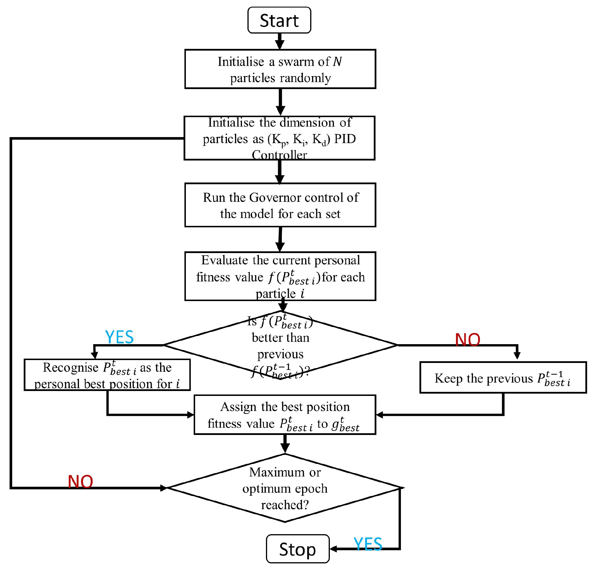
3. Particle Swarm Optimisation
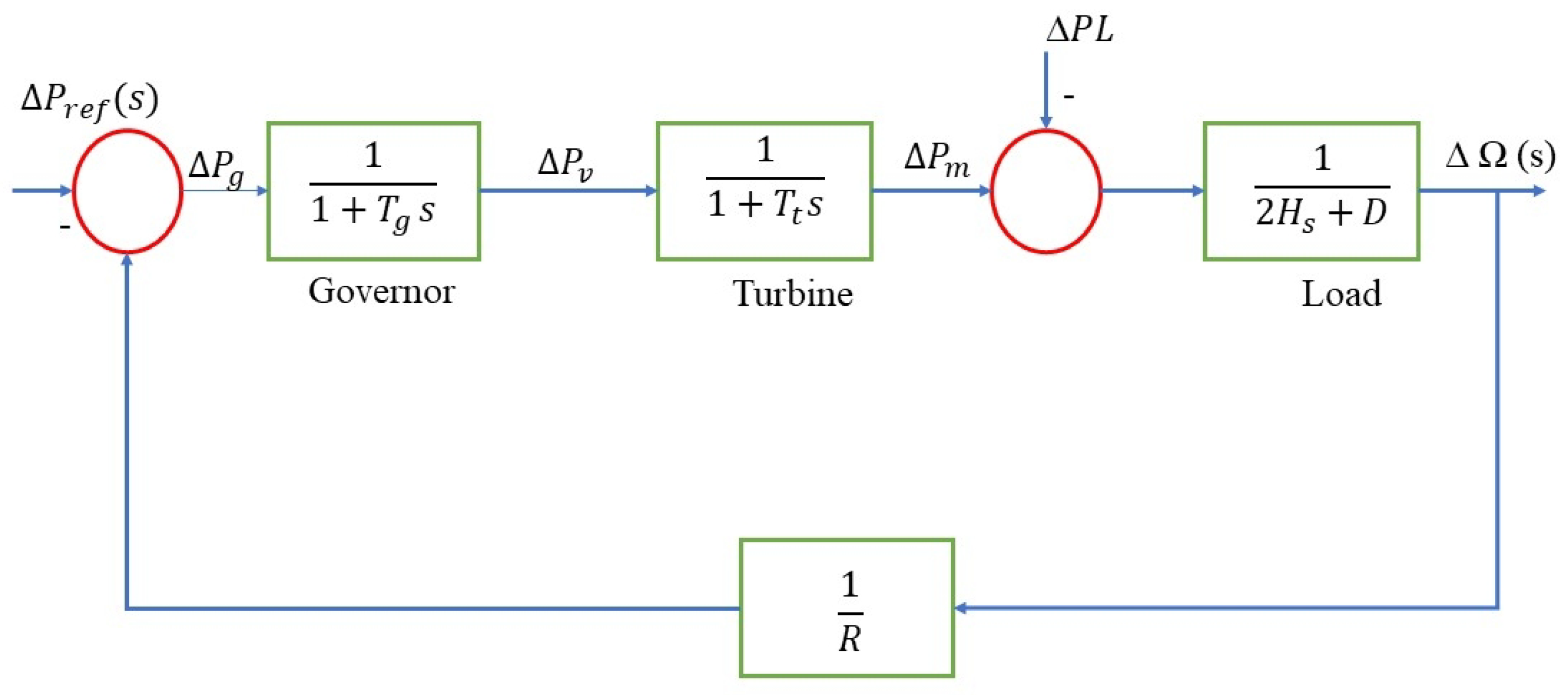
Particle swarm optimisation (PSO) is an intelligent evolutionary algorithm inspired by the social behaviour of flocking birds or schooling fish. Kennedy and Eberhart presented the PSO approach for the first time in 1997 [21,22]. The PSO algorithm can provide high-quality solutions in less time and with more steady convergence characteristics than other stochastic approaches, such as genetic algorithm [17,23].
In an n-dimensional space, let the position and individual i be represented as vectors X i = ( x i , . . . , x i n ) and V i = ( v i , . . . v i n ) in a PSO algorithm. Let
P b e s t i = ( x i p b e s t , . . . x i n p b e s t )
and
G b e s t i = ( x i g b e s t , . . . x n g b e s t )
Equations (1) and (2) are individual i g b e s t positions so far and their neighbours’ best position so far, respectively. Utilising this information, the PSO algorithm modifies the updated velocity of individual i using Equation (3):
V i k + 1 = ω V i k + c 1 r 1 × ( P b e s t i k X i k ) + c 2 r 2 × ( G b e s t i k X i k )
where
V i k is the velocity of individual i at an iteration k;
ω is the inertia weight parameter;
c 1 , c 2 is the acceleration coefficients;
r 1 , r 2 represents the ransom numbers between 0 and 1;
X i k is the position of individual i until iteration k;
P b e s t i k is the best position of individual iteration and G b e s t i k is the position of the group iteration.
The values of c 1 , c 2 , and ω are predetermined and, generally, the weight ω is shown as in Equation (4):
ω = ω m a x ( ω m a x ω m i n ) × i t e r I t e r m a x
where
ω m a x , ω m i n are the initial and final weights;
I t e r m a x is the maximum iteration number;
i t e r is the current iteration number.
The moves from the individual position of the current to the next velocity modified in Equation (3) is shown in Equation (5):
X i k + 1 = X i k + V i k + 1
PSO’s improved PID controller is intended for LFC and tie-power control. The objectives are to manage the frequency and inter-area tie-power with adequate oscillation damping while achieving good performance. The optimal values of the K P , K I , and K d parameters for a PID controller are quickly and precisely determined in this work utilising a PSO. In a typical PSO run, an initial population is produced at random. The original population is known as the 0th generation. Each member of the initial population has a unique performance index value. The PSO then generates a new population based on the performance index information. The system must be simulated to acquire the performance index value for each person in the present population. The PSO then uses the reproduction crossover and mutation operators to create the next generation of humans. These methods are continued until the population has converged and the optimal parameter value has been identified [24].
Figure 2 represents a flowchart model of the PSO step-by-step algorithm implementation. We set the parameters for the PSO algorithm, such as the number of particles, maximum iterations, and inertia weight. Then, we set the particle positions and speeds at random inside the search space. We estimate the fitness function for each particle using the LFC problem, and the fitness function should represent the system’s performance, such as frequency deviation and tie-line power deviation. Then update each particle’s own best position and fitness. We then update the swarm’s overall best position and fitness, and the PSO method is used to update the velocity and location of each particle. The new velocity and location should fall inside the scope of the search. This system is repeated until the maximum number of iterations is achieved or a good solution is discovered by using the best control action for the power system to keep frequency and tie-line power variations within acceptable limits.

4. System Model

The load frequency control strategy’s primary goal is to offer consumers high-quality, dependable electricity within an integrated system. Variations in active power cause the system’s frequency to fluctuate. As a result, a control technique is developed to regulate load frequency regulation using control loops. Two typical techniques, transfer function and state variable, are used to convert the power system model into a mathematical model by making appropriate assumptions [25,26,27].
A section of the transfer function model of the Delta power station Nigeria is designed as shown in Figure 3, and the primary sections are explained below.

4.1. Generator Model

The Generator equation has been derived from the swing equation in [28] as shown in Equation (6):
Δ ω ( s ) = 1 2 H s [ Δ P m ( s ) + Δ P g s ( s ) Δ P e ( s ) ]
where
Δ P m is the change in mechanical power;
Δ P g s is the power from the generating station;
Δ P e net change in the electrical load demand;
H is the generator inertia constant.

4.2. Load Model

The power system includes assistive and inductive loads that are frequency independent and dependent. As a result, the net change in load power may be defined as the sum of frequency-sensitive and frequency-insensitive load changes [29]. Some of the factors that affect the electric load include:
Meteorological factors: weather, climate, temperature, humidity, and solar radiation.
Temporal or calendar factors: the hours of the day, the days of the week, the seasons, and so forth.
Economic factors: industrial development, GDP, and so on.
Unexpected factors: sporting activities, festivals, etc.
Client factors: consumption type, building size, electric appliances, workforce count, etc. This is represented in Equation (7) below:
Δ P e ( s ) = Δ P L + D Δ ω
where Δ P L is the frequency-independent load change, D Δ ω is the sensitive load frequency change, and D is the ratio of percentage change in load to the frequency. The interaction between load variation and frequency fluctuation may be represented in Equation (8), as expressed below:
Δ P L ( f r e q ) = D Δ ω = Δ P L ( f r e q ) Δ ω

4.3. Turbine or Prime Mover Model

The turbine is the source of mechanical power, which derives its energy from the combustion of coal or gas or nuclear fission. The turbine’s transfer function may be expressed as the ratio of the change in mechanical output power Δ P m ( s ) to the change in steam valve position Δ P v ( s ) given in Equation (9):
G T ( s ) = Δ P m ( s ) Δ P v ( s ) = 1 1 + s τ t
where τ t is the turbine time constant.

4.4. Governor Model

The speed governor operates as a comparator [30], as expressed in Equation (10) below:
Δ P g ( s ) = Δ P r e f ( s ) 1 R Δ ω ( s )
where Δ P g is the power output of the governor, Δ P r e f is the reference set power, and R is the speed regulation. Equation (11) expresses the relationship between governor input and valve opening, as shown below.
Δ P v ( s ) = 1 1 + s τ g Δ P g ( s )
where τ g is the governor time constant in seconds.

4.5. The Proportional Integral Derivative (PID) Controller

PID controllers are commonly used in industrial control systems as a control loop fed back. It computes the difference between the measured process variable and the intended set point. PID settings are fine-tuned to guarantee good closed-loop performance. They are used to increase dynamic performance and lower steady-state error [31]. The gains are automatically achieved by tuning the model in MATLAB simulations to obtain ( K p , K i , K d ) , where K p decreases the rise time, K d reduces the overshoot and the setting time, and K i eliminates the steady-state error. In [32], the area control error theory associated with the PID control system is as shown in Equations (12)–(14) below.
P o u t = K p e ( t )
I o u t = K i 0 t e ( t ) d t
D o u t = K d d d t e ( t )
where
K p is the proportional gain;
K i is the integral gain;
K d is the derivative gain.
The transfer function of the controller is shown in Equation (15) below:
G P I D ( s ) = K p + K i s + K d s
and the control signal for maintaining the system frequency is shown in Equation (16).
U ( s ) = G P I D ( s ) × A C E ( s )
Here, A C E is the area control error of the system, and U is the governor’s input signal for managing the valve output based on the power system’s load demand. The A C E = B × Δ ω and B are the bias factors, as B = 1 R + D , and D ω is the frequency deviation.
The PSO-PID (particle swarm optimisation–proportional integral derivative) controller algorithm has several advantages over other conventional methods in load frequency control (LFC), including:
  • Better performance: The PSO-PID controller algorithm has been found to provide better control performance than conventional PID controllers in LFC systems. This is due to the ability of PSO to optimise the PID parameters to achieve the desired control objective.
  • Robustness: The PSO-PID controller algorithm is robust and can handle variations in load and system parameters, which are common in power systems.
  • Flexibility: The PSO-PID controller algorithm can be easily adapted to different power system models and can be used to control different types of generators.
  • Fast convergence: The PSO algorithm has fast convergence compared to other optimisation techniques, which makes it suitable for real-time control applications.
  • Easy to implement: The PSO-PID controller algorithm is easy to implement and does not require complex mathematical models or sophisticated programming skills.
Overall, the PSO-PID controller algorithm has proven to be an effective and efficient approach for load frequency control (LFC) in power systems, offering better control performance, robustness, flexibility, fast convergence, and ease of implementation.

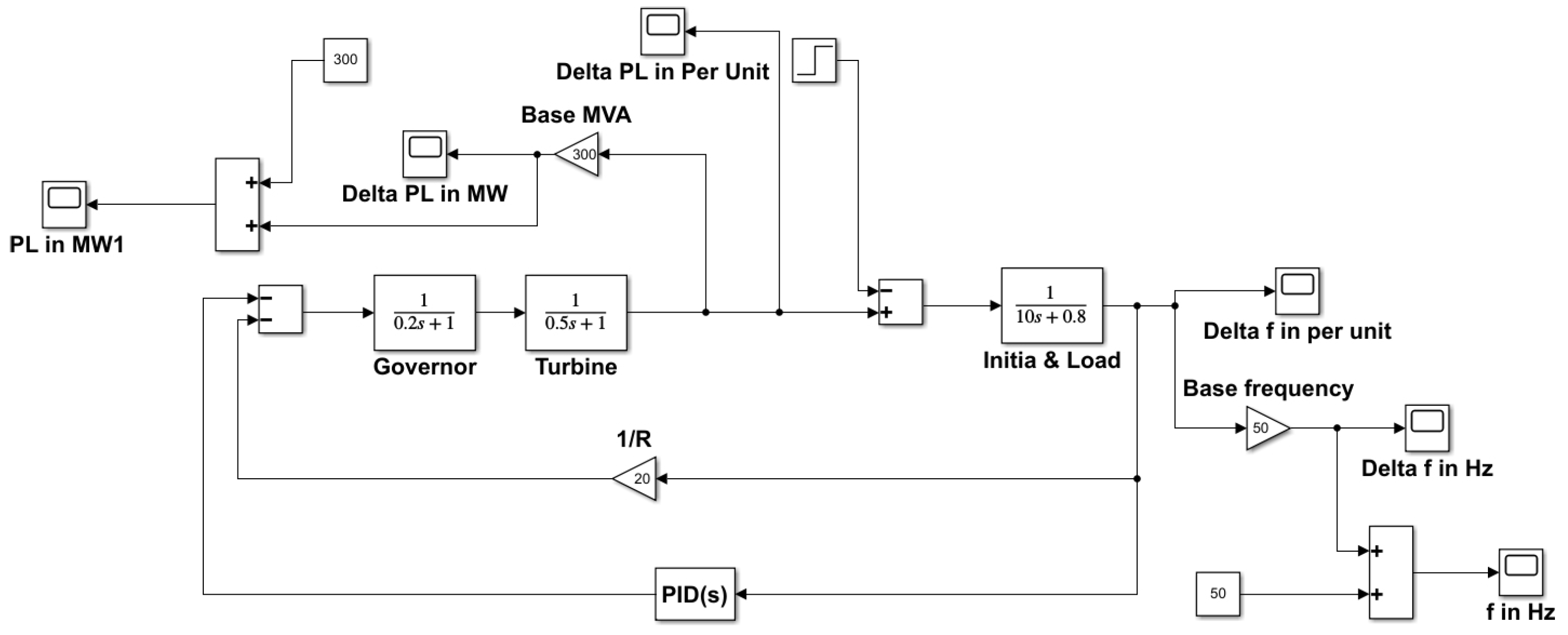
5. Modelling of the Proposed Power System

The proposed model is the Delta thermal generating station, a part of the Nigeria transmission line model with the following specifications, as shown in Table 1 below:
The Simulink model for frequency control was generated using the transfer functions of the modelled power network using the MATLAB/Simulink environment. The PID controller gain value was optimised and implemented using a distinct PSO technique-coding mfile in MATLAB. The nominal system parameter values were taken from Table 1 to normalise the frequency and modelled as shown in Figure 4 with the introduction of the PID controller. The governor speed regulation R is 0.05 PU, so 1 R is 20.
The controller gain value is determined by selecting the objective function in which ITAE was used as a desired output. Then, a population of particles was initialised where each particle represents a potential set of controller gain values of 0.9994, 0.7741, and 0.1858 for K p , K i , and K d , respectively, with the velocity vector. Then, we evaluated the fitness performance of each particle by calculating the objective function value based on the controller gain values. We updated the particle velocity and position to determine its best position and global best. These processes are repeated in multiple iterations to decide the termination condition, extract the best solution, and implement the controller. It is important to note that the success of the PSO algorithm in determining optimal controller gain values depends on factors such as the complexity of the control problem, the choice of the objective function, and the proper tuning of PSO parameters like swarm size, inertia weight, acceleration coefficients, and termination criteria.

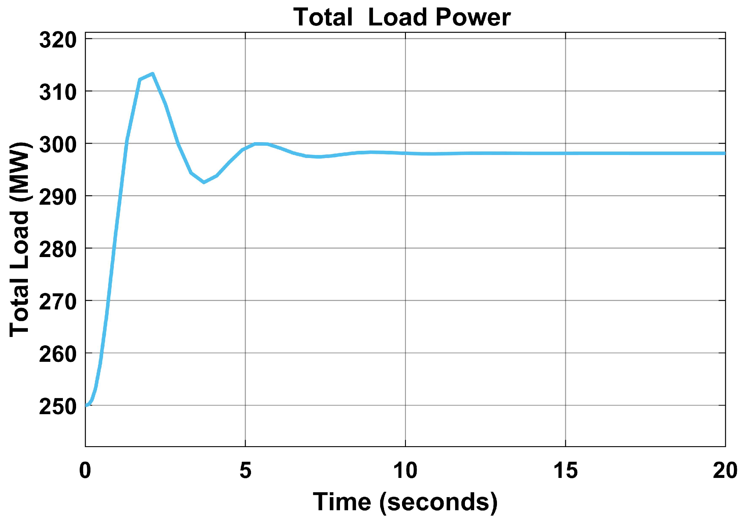
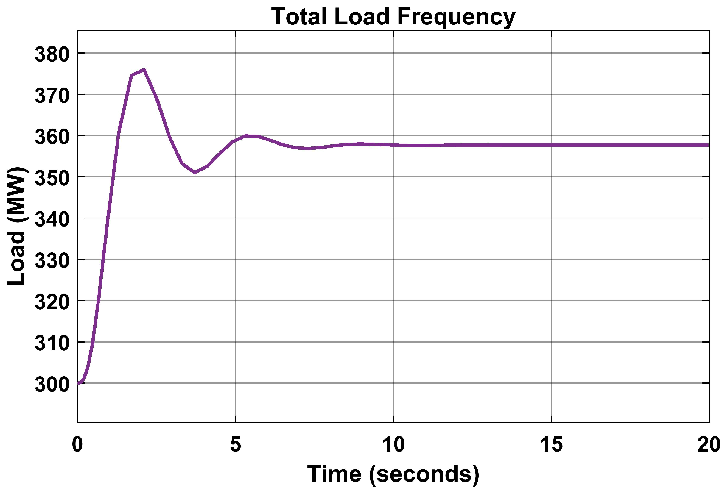
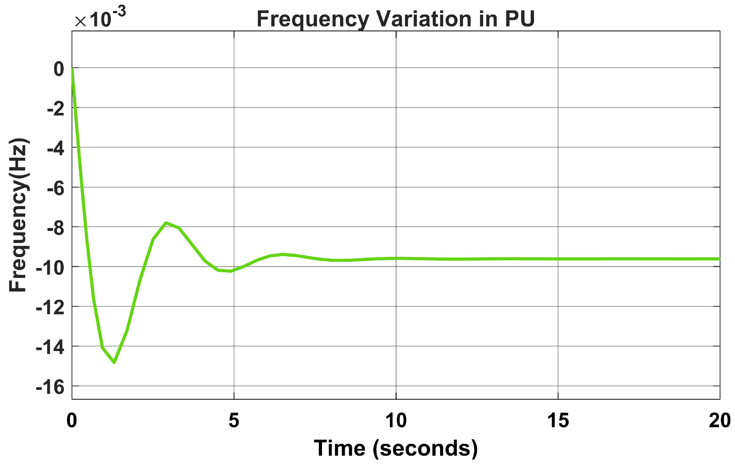
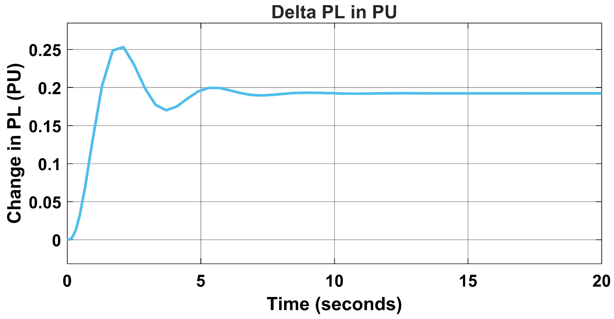
6. Results and Discussion

The system was modelled using the design parameters in Table 1 to design the model in Figure 1, the system was implemented using MATLAB, and the mfile code was executed for the PSO algorithm. The PID controller was tuned by minimising the ITAE for optimal performance. The optimised parameters were used to determine the effectiveness of the proposed technique.
Figure 5 represents the base frequency of the base load without the PID controller and when the PSO parameters have not been fine-tuned. There was an overshoot of 49.6 Hz, which later changed to 49.55 Hz, causing a variation in the load frequency.
In Figure 6, the PID controller was applied to the model without the PSO algorithm. The frequency reluctantly moved to 50 Hz, and the settling time was 5 to 10 s before normalising.
The time delay affects the power system and can lead to power loss; therefore, there is a need for a fast and accurate settling time of the load frequency.
In Figure 7, the base load was also affected by a drop from 300 MW to 299 MW, and about 1 MW of electricity was lost due to a fault in the load frequency.
When the total load frequency was increased to 350 MW, there was an overshoot due to overcurrent, as seen in Figure 8.
The frequency variation deviated rapidly, as seen in Figure 9 without the PID controller, and normalised with the introduction of the PID controller, as seen in Figure 10.
To maintain the load frequency with minimum time delay and overshoot, the PSO algorithm is introduced to the model.

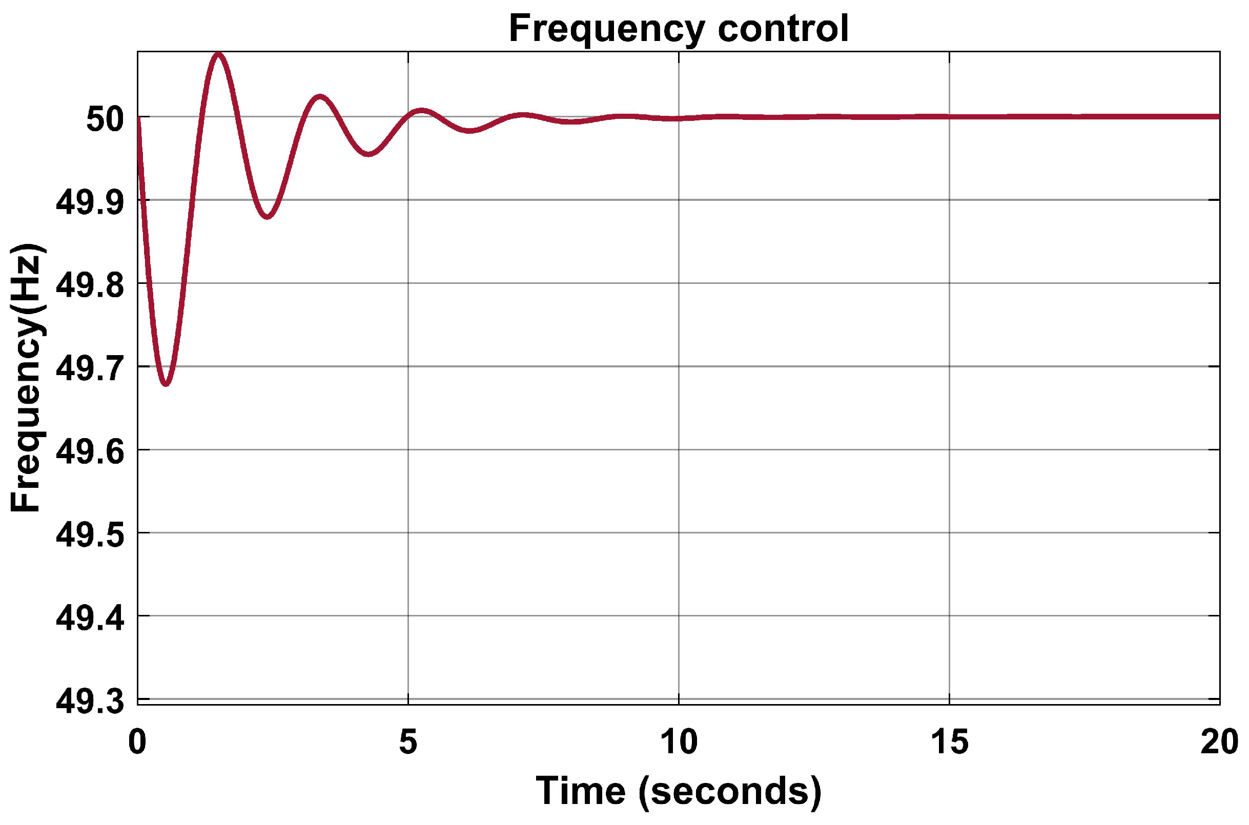
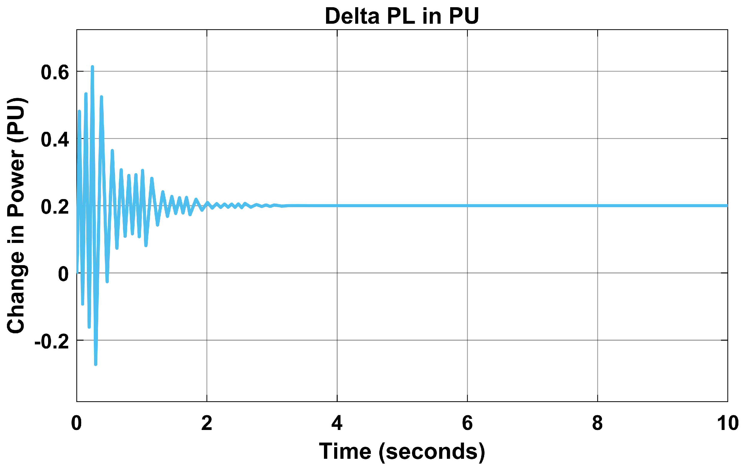
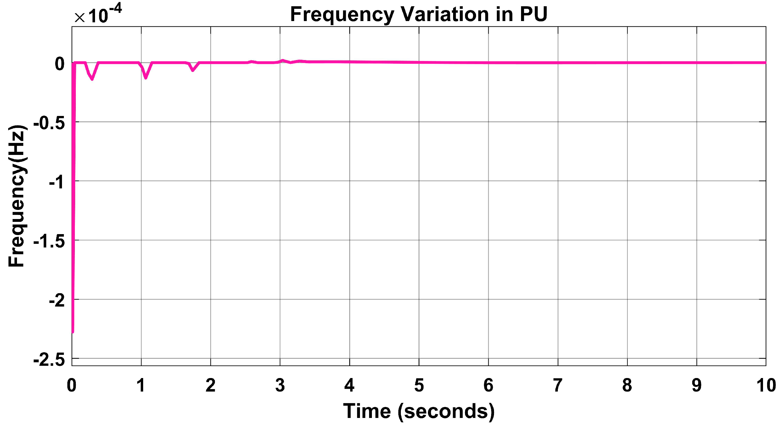
6.1. Frequency Control Using the PSO Algorithm

The PSO algorithm was applied using MATLAB Code to Figure 1, increasing the load to 360 MW for the changes. In addition, the combined frequency changes, as explained in the results.
In Figure 11, the change in base load was changed due to load frequency variation, but this was normalised using the proposed algorithm from 0.19 PU to 0.2 PU, as seen in Figure 12.
In addition, the variation in load changes from 0.5 s in Figure 11 to 0.2 s in Figure 12. The change in the settling time made the proposed model more reliable than the PID controller, hence, faster in fault clearing time.
In Figure 13, the combined frequency response of the PID controller and the PSO algorithm shows that the proposed algorithm’s performance is better based on the settling time and fault clearing time of zero seconds using the PSO algorithm.
The frequency variation in PU was reduced from 0.8 s in Figure 10 to zero seconds using the PSO and the PID controller in Figure 14.
The performance indices of the proposed model are measured by the ITAE, which is 0.0005757. This is minimal as compared to [33] with 0.7741 for K p , 0.9994 for K i , and 0.1850 for K d . In addition, the model’s system dynamic response is tested by varying the load from 300 MW to 350 MW at a load variation of 0.2 PU.

6.2. Comparing the PSO-PID Controller Algorithm with Other LFC Techniques

The PSO-PID controller algorithm was compared to other techniques, as shown in Table 2. The algorithm was compared with the fuzzy controller with a settling time of 15.4 s [34] as compared with the proposed algorithm of 0.00 s settling time and a performance index of 0.0005757 ITAE. In addition, the settling times of the ANN SVM, ANFI, and ANN-PID controllers are higher than for the proposed algorithm, as shown in Table 2. Compared to PI and PID controllers, the PSO-PID controller shows superior quick settling time, reduced overshoot and undershoot, and fewer oscillations.
The PSO algorithm has a potential for premature coverage because the algorithm has several parameters, such as the population size, inertia weight, and acceleration coefficients, which must be appropriately selected to achieve optimal performance. The performance of the PSO-PID controller in LFC may be sensitive to the values chosen for these parameters, and sub-optimal parameter settings could result in reduced controller performance or convergence to local optima. Therefore, the proposed algorithm increases the iteration value to reduce premature convergence for optimal results, as seen in Figure 15.
Other methods can be used to reduce frequency variation or control power system and frequency stability, and these include
  • Automatic generation control (AGC): AGC is a control system that adjusts the output of generators in response to variations in frequency to maintain the balance between generation and load. When the frequency falls, AGC may automatically boost the output of other generators to compensate for the lost generation, restoring the frequency to its usual range.
  • Load shedding: Load shedding is a control method used to minimise power system demand during times of low generation or high demand. Load shedding may be used to lower the load on the system and assist in restoring the frequency to its normal range in the case of a frequency deviation. This may include disconnecting individual loads or lowering the electricity usage of specific consumers or areas.
  • Reserve capacity: The generating capacity available to the system beyond the predicted demand is called reserve capacity. Reserve capacity is crucial because it acts as a buffer to absorb unforeseen occurrences like the abrupt loss of a generator. By ensuring that the system has appropriate reserve capacity, the frequency variation may be corrected rapidly without jeopardising system stability.
  • Interconnection with surrounding systems: Interconnection with neighbouring power systems may offer new generation sources while also assisting in balancing energy supply and demand across a larger region. Interconnection with surrounding systems may give extra assistance to help restore the frequency to its normal range in the case of a frequency deviation.
  • Energy storage: Energy storage technologies, such as batteries or pumped hydro storage, may be utilised to store surplus generating capacity and release it as required, therefore assisting in maintaining system stability. Frequency variation may be swiftly rectified and system stability maintained by deploying energy storage to offer extra assistance to the system during times of low generation.
    Power system operators may use these steps to guarantee that the frequency stays within a small range, reducing the danger of power outages or equipment damage.

7. Conclusions

A novel particle swarm optimised LFC was examined in this work for autonomous load frequency regulation of the Delta thermal generating station, a part of the Nigeria transmission line model. The network was modelled without the PID controller using the system parameters generated through a mathematical model, and then the PID controller was introduced for parameter tuning. The mfile of the PSO algorithm code was generated using MATLAB to generate the K p , K i , and K d parameters. First, more adaptive tuning mechanisms for the PID controller settings were obtained, and the system’s sensitivity was raised. It was shown that the suggested control algorithm is effective and improves system performance significantly. As a result, the suggested PSO-PID controller is recommended for producing high-quality, dependable electricity. Moreover, the PSO-PID algorithm produces 0.00 s settling time and 0.0005757 ITAE. It is essential to carefully consider potential drawbacks like complexity and computational overhead, sensitivity to algorithm parameters, potential parameter convergence, and limited interpretability and assess their impact on the specific LFC application before implementing a PSO-PID controller in a power system. Proper parameter tuning, robustness analysis, and performance evaluation are crucial to ensure the effective and reliable operation of the controller. Compared to conventional methods, the suggested controller algorithm is relatively reliable and accurate in power system management and protection load frequency control. This work can be improved by including more generating stations synchronised into a single network.
Overall, the PSO-PID controller algorithm has proven to be an effective and efficient approach for load frequency control (LFC) in power systems, offering better control performance, robustness, flexibility, fast convergence, and ease of implementation.

Author Contributions

Conceptualisation, V.N.O. and K.A.A.G.; methodology, V.N.O.; software, validation, formal analysis, V.N.O.; investigation, resources, data curation, V.N.O., K.A.A.G. and S.H.; writing—original draft preparation, V.N.O.; writing—review and editing, K.A.A.G. and S.H.; visualisation, and supervision, K.A.A.G. and S.H. All authors have read and agreed to the published version of the manuscript.

Funding

This research received no external funding.

Conflicts of Interest

The authors declare no conflict of interest.

Abbreviations

The following abbreviations are used in this manuscript:
LFCLoad Frequency Control
PSOParticle Swarm Optimisation
PDPIProportional Derivative Proportional Integral
PIDProportional Integral Derivative
DWTDiscrete Wavelet Transform
ITAEIntegral Time Absolute Error
GRCGeneration Rate Constraint
AGCAutomatic Generation Control
MPCModel Predictive Control
GAGenetic Algorithm

References

  1. Parmar, K.S.; Majhi, S.; Kothari, D. Load frequency control of a realistic power system with multi-source power generation. Int. J. Electr. Power Energy Syst. 2012, 42, 426–433. [Google Scholar] [CrossRef]
  2. Sarker, M.A.A.; Hasan, A.K. Load frequency Control in Power system. SEU J. Sci. Eng. 2016, 10, 24–30. [Google Scholar]
  3. Samarakoon, K.B. Use of Smart Meters for Frequency and Voltage Control. Ph.D. Thesis, Cardiff University, Cardiff, UK, 2012. [Google Scholar]
  4. Indonesia, B.K. Rules for Machinery Installations. Rules Classif. Constr. 2019, 3, 2–26. [Google Scholar]
  5. Zografos, D. Power System Inertia Estimation and Frequency Response Assessment. Ph.D. Thesis, KTH Royal Institute of Technology, Stockholm, Sweden, 2019. [Google Scholar]
  6. Shayeghi, H.; Jalili, A.; Shayanfar, H. Multi-stage fuzzy load frequency control using PSO. Energy Convers. Manag. 2008, 49, 2570–2580. [Google Scholar] [CrossRef]
  7. Anuradhika, K.; Dash, P. Genetic Algorithm-Based Load Frequency Control of a Grid-Connected Microgrid in Presence of Electric Vehicles. In Sustainable Energy and Technological Advancements: Proceedings of ISSETA 2021; Springer: Berlin/Heidelberg, Germany, 2022; pp. 435–447. [Google Scholar]
  8. Safari, A.; Babaei, F.; Farrokhifar, M. A load frequency control using a PSO-based ANN for micro-grids in the presence of electric vehicles. Int. J. Ambient Energy 2021, 42, 688–700. [Google Scholar] [CrossRef]
  9. Dhillon, S.S.; Lather, J.S.; Marwaha, S. Multi area load frequency control using particle swarm optimization and fuzzy rules. Procedia Comput. Sci. 2015, 57, 460–472. [Google Scholar] [CrossRef] [Green Version]
  10. Lastomo, D.; Setiadi, H.; Djalal, M.R. Enabling PID and SSSC for load frequency control using Particle Swarm Optimization. In Proceedings of the 2017 3rd International Conference on Science in Information Technology (ICSITech), Bandung, Indonesia, 25–26 October 2017; IEEE: New York, NY, USA; pp. 182–187. [Google Scholar]
  11. Gupta, D.K.; Jha, A.V.; Appasani, B.; Srinivasulu, A.; Bizon, N.; Thounthong, P. Load frequency control using hybrid intelligent optimization technique for multi-source power systems. Energies 2021, 14, 1581. [Google Scholar] [CrossRef]
  12. Sahoo, P.K.; Mohapatra, S.; Gupta, D.K.; Panda, S. Multi verse optimized fractional order PDPI controller for load frequency control. IETE J. Res. 2022, 68, 3302–3315. [Google Scholar] [CrossRef]
  13. Sakellariou, N. Current and potential decommissioning scenarios for end-of-life composite wind blades. Energy Syst. 2018, 9, 981–1023. [Google Scholar] [CrossRef]
  14. Kom, C.H. Understanding interphase power controller: A description. J. Electr. Eng. Electron. Control Comput. Sci. 2020, 6, 19–24. [Google Scholar]
  15. Fan, W.; Hu, Z.; Veerasamy, V. PSO-Based Model Predictive Control for Load Frequency Regulation with Wind Turbines. Energies 2022, 15, 8219. [Google Scholar] [CrossRef]
  16. Kunya, A.; Argin, M.; Kucuksari, S. Optimal load frequency control of multi-area power system considering incremental control action. In Proceedings of the 2019 IEEE Texas Power and Energy Conference (TPEC), College Station, TX, USA, 7–8 February 2019; IEEE: New York, NY, USA, 2019; pp. 1–6. [Google Scholar]
  17. Gözde, H.; Taplamacıoğlu, M.; Kocaarslan, I.; Çam, E. Particle swarm optimization based load frequency control in a single area power system. Univ. Pitesti Comput. Sci. Sci. Bull. 2008, 2. [Google Scholar]
  18. Sarir, N.; Morsli, S.; Allaoui, T.; Denai, M. Optimal fractional-order pi control design for a variable speed PMSG-based wind turbine. J. Eur. Syst. Autom. 2021, 915–922. [Google Scholar]
  19. Kullapadayachi Govindaraju, S.; Sivalingam, R.; Panda, S.; Sahu, P.R.; Padmanaban, S. Frequency Control of Power System with Distributed Sources by Adaptive Type 2 Fuzzy PID Controller. Electr. Power Comp. Syst. 2023, 1–22. [Google Scholar] [CrossRef]
  20. Qin, Z.; Liu, D.; Hua, H.; Cao, J. Privacy preserving load control of residential microgrid via deep reinforcement learning. IEEE Trans. Smart Grid 2021, 12, 4079–4089. [Google Scholar] [CrossRef]
  21. Kennedy, J.; Eberhart, R.C. A discrete binary version of the particle swarm algorithm. In Computational Cybernetics and Simulation Proceedings of the 1997 IEEE International Conference on Systems, Man, and Cybernetics, Orlando, FL, USA, 12–15 October 1997; IEEE: New York, NY, USA, 1997; Volume 5, pp. 4104–4108. [Google Scholar]
  22. Shariati, M.; Mafipour, M.S.; Mehrabi, P.; Bahadori, A.; Zandi, Y.; Salih, M.N.; Nguyen, H.; Dou, J.; Song, X.; Poi-Ngian, S. Application of a hybrid artificial neural network-particle swarm optimization (ANN-PSO) model in behavior prediction of channel shear connectors embedded in normal and high-strength concrete. Appl. Sci. 2019, 9, 5534. [Google Scholar] [CrossRef] [Green Version]
  23. Angeline, P.J. Using selection to improve particle swarm optimization. In Proceedings of the 1998 IEEE International Conference on Evolutionary Computation Proceedings. IEEE World Congress on Computational Intelligence (Cat. No. 98TH8360), Anchorage, AK, USA, 4–9 May 1998; IEEE: New York, NY, USA, 1998; pp. 84–89. [Google Scholar]
  24. Rao, R.N.; Reddy, P.R.K. PSO based tuning of PID controller for a Load frequency control in two area power system. Int. J. Eng. Res. Appl. 2015, 1, 1499–1505. [Google Scholar]
  25. Mahboob Ul Hassan, S.; Ramli, M.A.; Milyani, A.H. Robust Load Frequency Control of Hybrid Solar Power Systems using Optimization techniques. Front. Energy Res. 2022, 10, 730. [Google Scholar] [CrossRef]
  26. Yang-Wu, S.; Xun, M.; Ao, P.; Yang-Guang, W.; Ting, C.; Ding, W.; Jian, Z. Load frequency control strategy for wind power grid-connected power systems considering wind power forecast. In Proceedings of the 2019 IEEE 3rd Conference on Energy Internet and Energy System Integration (EI2), Changsha, China, 8–10 November 2019; IEEE: New York, NY, USA, 2019; pp. 1124–1128. [Google Scholar]
  27. Tur, M.R.; Wadi, M.; Shobole, A.; Ay, S. Load frequency control of two area interconnected power system using fuzzy logic control and PID controller. In Proceedings of the 2018 7th International Conference on Renewable Energy Research and Applications (ICRERA), Paris, France, 14–17 October 2018; IEEE: New York, NY, USA, 2018; pp. 1253–1258. [Google Scholar]
  28. Qiu, Q.; Ma, R.; Kurths, J.; Zhan, M. Swing equation in power systems: Approximate analytical solution and bifurcation curve estimate. Chaos Interdiscip. J. Nonlinear Sci. 2020, 30, 013110. [Google Scholar] [CrossRef]
  29. Glover, J.D.; Sarma, M.S.; Overbye, T. Power System Analysis & Design, SI Version; Cengage Learning: Boston, MA, USA, 2012. [Google Scholar]
  30. Kumari, K.; Shankar, G.; Kumari, S.; Gupta, S. Load frequency control using ANN-PID controller. In Proceedings of the 2016 IEEE 1st International Conference on Power Electronics, Intelligent Control and Energy Systems (ICPEICES), Delhi, India, 4–6 July 2016; IEEE: New York, NY, USA, 2016; pp. 1–6. [Google Scholar]
  31. Aung, S.S.; Htike, Z.M. Modeling and Simulation of Load Frequency Control for Three Area Power System Using Proportional Integral Derivative (PID) Controller. Am. Sci. Res. J. Eng. Technol. Sci. 2016, 26, 301–315. [Google Scholar]
  32. Tan, W. Unified tuning of PID load frequency controller for power systems via IMC. IEEE Trans. Power Syst. 2009, 25, 341–350. [Google Scholar] [CrossRef]
  33. Dhanasekaran, B.; Kaliannan, J.; Baskaran, A.; Dey, N.; Tavares, J.M.R. Load Frequency Control Assessment of a PSO-PID Controller for a Standalone Multi-Source Power System. Technologies 2023, 11, 22. [Google Scholar] [CrossRef]
  34. Çam, E.; Kocaarslan, I. Load frequency control in two area power systems using fuzzy logic controller. Energy Convers. Manag. 2005, 46, 233–243. [Google Scholar] [CrossRef]
  35. Çam, E. Application of fuzzy logic for load frequency control of hydroelectrical power plants. Energy Convers. Manag. 2007, 48, 1281–1288. [Google Scholar] [CrossRef]
  36. Arya, Y. Improvement in automatic generation control of two-area electric power systems via a new fuzzy aided optimal PIDN-FOI controller. ISA Trans. 2018, 80, 475–490. [Google Scholar] [CrossRef]
  37. Mohammed, A.J.; Al-Majidi, S.D.; Al-Nussairi, M.K.; Abbod, M.F.; Al-Raweshidy, H.S. Design of a Load Frequency Controller based on Artificial Neural Network for Single-Area Power System. In Proceedings of the 2022 57th International Universities Power Engineering Conference (UPEC), Istanbul, Turkey, 30 August–2 September 2022; IEEE: New York, NY, USA, 2022; pp. 1–5. [Google Scholar]
  38. Osman, A.M.; Magzoub, M.A.; Salem, A. Load Frequency Control in Two Area Power System using GA, SA and PSO Algorithms: A Comparative Study. In Proceedings of the 2021 31st Australasian Universities Power Engineering Conference (AUPEC), Perth, WA, Australia, 26–30 September 2021; IEEE: New York, NY, USA, 2021; pp. 1–8. [Google Scholar]
  39. Babakhani, Q.M. Load Frequency Control in Two Area Power System Using Sliding Mode Control. J. Artif. Intell. Electr. Eng. 2014, 3, 24–36. [Google Scholar]
  40. Appikonda, P.; Kasibhatla, R.S. Design of support vector machine controller for hybrid power system automatic generation control. Energy Sources Part A Recover. Util. Environ. Eff. 2022, 44, 3883–3907. [Google Scholar] [CrossRef]
  41. Hemeida, A.; Mohamed, S.; Mahmoud, M. Load frequency control using optimized control techniques. JES J. Eng. Sci. 2020, 48, 1119–11136. [Google Scholar] [CrossRef]
  42. Raj, T.D.; Kumar, C.; Kotsampopoulos, P.; Fayek, H.H. Load Frequency Control in Two-Area Multi-Source Power System Using Bald Eagle-Sparrow Search Optimization Tuned PID Controller. Energies 2023, 16, 2014. [Google Scholar] [CrossRef]
  43. Feleke, S.; Satish, R.; Salkuti, S.R.; Abdelaziz, A.Y. Load Frequency Control in Two-Area Interconnected Systems Using DE-PID and PSO-PID. In Power Quality in Microgrids: Issues, Challenges and Mitigation Techniques; Springer: Berlin/Heidelberg, Germany, 2023; pp. 391–407. [Google Scholar]
  44. Nireekshana, N.; Ramachandran, R.; Narayana, G. A Novel Swarm Approach for Regulating Load Frequency in Two-Area Energy Systems. Int. J. Electr. Electron. Res. 2023, 11, 371–377. [Google Scholar] [CrossRef]
Figure 1. Complete simulated model with PID controller.
Energies 16 05748 g001
Figure 2. The flow chart model for the PSO-PID algorithm.
Energies 16 05748 g002
Figure 3. Transfer function model of the Delta power station.
Energies 16 05748 g003
Figure 4. System model with PID controller.
Energies 16 05748 g004
Figure 5. Load frequency without PID controller.
Energies 16 05748 g005
Figure 6. Load frequency with PID controller.
Energies 16 05748 g006
Figure 7. Base load without PID controller.
Energies 16 05748 g007
Figure 8. Total load frequency with PID controller.
Energies 16 05748 g008
Figure 9. Frequency variation without PID controller.
Energies 16 05748 g009
Figure 10. Frequency variation using PID controller.
Energies 16 05748 g010
Figure 11. Change in load (PU) without PID controller.
Energies 16 05748 g011
Figure 12. Change in load (PU) with PSO-PID controller.
Energies 16 05748 g012
Figure 13. Combined frequency response using PSO-PID controller.
Energies 16 05748 g013
Figure 14. Frequency variation in PU using PSO-PID controller.
Energies 16 05748 g014
Figure 15. Iteration of the PSO algorithm.
Energies 16 05748 g015
Table 1. System parameters.
ParametersSpecification
Normal frequency (Hz)50 Hz
Turbine-rated power (PL)300 MW
The turbine time constant ( T t )0.5 s
Governor time constant ( T g )0.2 s
Governor speed regulation (R)0.05 PU
Generator inertia constant (H)5 s
Load variation (D)0.8
Table 2. Comparing the proposed model and the other algorithms used.
Controller UsedSettling
Time (s)
Controller
Error
OvershootReference
FUZZY Controller7.200.2%0.027[34]
Fuzzy Controller15.42.5%2.33[35]
PID Controller16.580.7320.0206[36]
ANN-PID Controller6.50.04%0.1090[30]
Optimal ANN50.00.06%3.4[37]
ANFIS Controller8.5-−0.45[38,39]
SVM Controller10.57.09%0.25[40]
GA-PID Controller21.80.0075%0.04[7]
GA-PID Controller5.00.50025%0.0[41]
BESSO-PID Controller10.4767-0.0001[42]
DE-PID Controller11.1892-0.001[43]
PID-PSO Controller2.930.055%0.052[44]
Proposed Algorithm with PID5.00.00057570.45
Proposed Algorithm with PSO-PID0.00.00057570.0
Disclaimer/Publisher’s Note: The statements, opinions and data contained in all publications are solely those of the individual author(s) and contributor(s) and not of MDPI and/or the editor(s). MDPI and/or the editor(s) disclaim responsibility for any injury to people or property resulting from any ideas, methods, instructions or products referred to in the content.

