Abstract
This manuscript presents a thorough review of unitized regenerative fuel cells (URFCs) and their importance in Remote Area Power Supply (RAPS). In RAPS systems that utilize solar and hydrogen power, which typically include photovoltaic modules, a proton exchange membrane (PEM) electrolyzer, hydrogen gas storage, and PEM fuel cells, the cost of these systems is currently higher compared to conventional RAPS systems that employ diesel generators or batteries. URFCs offer a potential solution to reduce the expenses of solar hydrogen renewable energy systems in RAPS by combining the functionalities of the electrolyzer and fuel cell into a single unit, thereby eliminating the need to purchase separate and costly electrolyzer and fuel cell units. URFCs are particularly well-suited for RAPS applications because the electrolyzer and fuel cell do not need to operate simultaneously. In electrolyzer mode, URFCs function similarly to stand-alone electrolyzers. However, in fuel cell mode, the performance of URFCs is inferior to that of stand-alone fuel cells. The presented review summarizes the past, present, and future of URFCs with details on the operating modes of URFCs, limitations and technical challenges, and applications. Solar hydrogen renewable energy applications in RAPS and challenges facing solar hydrogen renewable energy in the RAPS is discussed in detail.
1. Introduction
A significant portion of the world’s energy is reliant on unexplored fossil fuel reserves. The continued growth of the world population and economy drives the extensive usage of fossil fuels [1,2]. Global oil production is predicted to peak in 2021 and be depleted within 15 years, according to the US Department of Energy. Some claim that peak oil output has already occurred [3]. Oil prices are under tremendous pressure as demand for oil continues to rise while supply stays stable. However, within the scientific community, there is a consensus that the escalating levels of greenhouse gases and resulting climate change are directly linked to human activities, which have caused global warming. The burning of fossil fuels is a primary contributor to these activities and leads to increased greenhouse gas emissions. Therefore, it is of utmost importance to shift towards alternative energy sources and move away from fossil fuels in the coming decades.
The adoption of renewable energy sources like solar and wind power plays a crucial role in establishing a sustainable energy strategy and facilitating the shift away from fossil fuels [4]. However, solar and wind energy exhibit inherent variability due to short and long-term climatic cycles [5]. To tackle this challenge, there has been a longstanding proposal to generate hydrogen through the process of water splitting or other methods, storing it for later use in fuel cells or combustion when there are shortages of solar or wind power [6]. This concept, often referred to as the “hydrogen economy,” involves utilizing renewable-produced hydrogen for various applications such as transportation (including planes, cars, and trains), buildings, and industrial facilities [7,8]. Utilizing renewable energy sources to produce hydrogen is seen as ecologically responsible, eco-friendly, and widely regarded as the greenest option because it produces no greenhouse emissions upon combustion [9].
The final report from the G8 working group on renewable energy [10] underscores the significance of modern energy services for economic, social, and political development, as well as the promotion of human well-being and quality of life. For individuals residing in areas beyond the reach of conventional power distribution systems, Remote Area Power (RAP) systems serve as the sole viable solution. Presently, diesel power is commonly employed as a dependable source of electricity in many remote regions. Renewable solar and wind systems have emerged as appealing alternatives for curbing greenhouse gas emissions within RAP systems [11]. In such systems, short-term battery storage can be used to control the variation between day and season, although this is only suitable for bad weather. Extended-duration energy storage is required to meet long-term climate changes [12]. One of the key prerequisites for a successful energy system is a sustainable energy flow coupled with extra energy storage.
Numerous solar hydrogen renewable energy system initiatives have been introduced worldwide, such as Japan’s WE-NET, Germany’s PHEOBUS, and the United States’ HYSOLAR project [13]. A cost reduction strategy for solar hydrogen renewable energy systems involves implementing a unitized regenerative fuel cell (URFCs) unit that integrates the functions of both an electrolyzer and a fuel cell within a single entity. [14]. This integrated and reversible fuel cell system performs both electrolysis and fuel cell operations within a single device. Consequently, URFCs hold the potential to significantly reduce capital costs associated with remote solar hydrogen systems [15].
1.1. Current Status of URFCS
URFC technology initially found applications in hydrogen-based spacecraft and continuous power supply systems [16]. Proton Energy Systems Inc. leads the production of PEMFC (Proton Exchange Membrane Fuel Cell) [17]. The company utilizes first-generation URFCs, which rely on a PEM storage system, to deliver a reliable backup power supply in continuous power systems. However, the deployment and testing of these systems have been limited in terms of usage and performance evaluation. Lynntech Industries also offers Membrane Electrode Assemblies (MEAs) with diverse specifications for PEM-based Reversible Fuel Cells. Nevertheless, there has been minimal exploration of URFC performance under standard conditions. A comprehensive comparison of URFC performance involving different catalysts, loading densities, and design characteristics has not been reported. Theoretical modeling of URFC systems and their application in solar hydrogen renewable energy-based RAPS systems remain unexplored.
1.2. Contributions
The main contribution of the manuscript are as follows:
- Unitized regenerative fuel cells (URFCs) are discussed in this paper and their importance in Remote Area Power Systems (RAPSs) that use solar and hydrogen power.
- Through the integration of the electrolyzer and fuel cell into a single unit, URFCs can reduce the expenditures involved in solar hydrogen renewable energy systems for RAPS.
- URFCs have the potential to address this cost disparity since they are cheaper than conventional RAPS systems using diesel generators or batteries.
- Due to their ability to operate independently, URFCs are well-suited for RAPS applications because they allow for efficient energy management.
- There is an in-depth review of URFCs’ past, present, and future, including how they operate, their limitations, technical challenges, and a variety of applications they can be utilized for. Furthermore, solar hydrogen renewable energy applications are discussed, along with their challenges and prospects.
2. URFCs History
In 1839, Sir William Grove was recognized as the pioneer who initially conceptualized the fuel cell. The popularity of fuel cells experienced significant growth during the 1950s, primarily driven by the demand for secure, space-efficient, and relatively lightweight power generation technology in spacecraft. Hydrogen and oxygen were the primary elements used in fuel cells for the space programs of the United States and the Soviet Union. However, Sir William Grove also recognized the potential of a reversible cell that could both generate electrolytes and produce energy, making it a valuable component for energy storage systems. The gases have the potential to be used to store water in water tanks and power in fuel cells. Through a lifetime test of a single-cell PEM URFC in 1973, General Electric (GE) provided preliminary proof for the unitized regenerative fuel cell (URFC) theory. The test demonstrated significant cell reversal without membrane destruction, similar to Nafion 120 by DuPont, along with the catalyst [18].
In 1992, Aero Vironment Inc. and the Lawrence Livermore National Laboratory (LLNL) began a collaborative effort to investigate the feasibility of unitized regenerative fuel cells (URFCs) as a potential energy storage solution for HALE-SRA (High Altitude Long Endurance Solar Rechargeable Aircraft). The research for this project received financial backing from the Ballistic Missile Defense Organization (BMDO). In ordinary aircraft, electricity from solar cells was fed to the fans throughout the day, with additional URFCs running in (electrolyzer mode) E-mode to supply hydrogen and oxygen as shown in Figure 1. The hydrogen and oxygen gasses emanating from the URFC have been riffed to URFC, now running (fuel cell mode) FC-mode in order to keep the propellers moving and pushing the aircraft overnight.

Figure 1.
URFC-based energy storage solar-powered aircraft model [18].
In 1993, LLNL designed and built the first portable URFC demonstration unit with the help of Hamilton Standard [19]. The fuel cell enters fuel cell mode by turning on the URFC after being charged for a brief period, ranging from seconds to minutes. The URFC presentation was tremendously successful, and as a result, its duplicates received invitations to take part in international events where they were inspected by academics, decision-makers, and financial industry experts. Proton energy systems recognized the value of this early sale of URFC toys and created its own toys for sale as shown in Figure 2 with less than 5 watts of mobile applications [20]. The development of URFC technologies with applications resembling those in aircraft began in the late 1990s. LLNL used the reversible PEM technology in the aerospace industry, which was developed by the Hamilton Standard (HS) over the difficult problem of solar aircraft performance at night before 1998 [19].
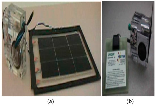
Figure 2.
Demo unit of standard URFC LLNL/Hamilton (a), Demo unit of URFC Proton (b) [19].
Hydrogen and oxygen-based URFC is an ideal combination for rocket engines used by vehicle launchers, such as the main space shuttle engine. Figure 3 represents the demo unit of standard URFC LLNL/Hamilton which is used in the ship.
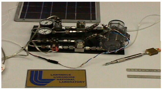
Figure 3.
Demo unit of standard URFC LLNL/Hamilton [19].
In the mid-1990s, the Lawrence Livermore National Laboratory (LLNL) achieved a successful substitution of the primary fuel cell experiment (FC), measuring 46 cm2 in active area, with a unitized regenerative fuel cell (URFC). Additionally, LLNL has further developed a URFC system specifically designed for lightweight pressure vessels, catering to terrestrial vehicles with non-emission requirements.
2.1. Regenerative Fuel Cells (RFCS)
An electrolyzer and a fuel cell can both be produced by one device or by a networked system [21]. A reversible fuel cell (RFC) uses electrolysis to separate the components of water into hydrogen and oxygen as the main reversible process, as depicted in Equation (1):
H2O + energy ↔ 2H+ + ½ O2 + 2e−.
Research has been dedicated to investigating reversible fuel cells (RFCs) that center around water-splitting reactions, with specific emphasis on zinc–oxygen and hydrogen–halogen reactions [22]. The electrolyzer mode (E-mode) of an RFC works by splitting liquid water into hydrogen and oxygen using the electrical input of the cell. The RFC may operate as a fuel cell (FC) and generate electricity while producing water since these gases are stored and can be reintroduced into it. Another alternative is to solely collect hydrogen, in which case the RFC would require atmospheric oxygen to function as a fuel cell. Thus, the reversibility of water dissociation and reforming processes is a fundamental tenet of RFC theory. RFCs are a comprehensive energy storage system for future use, in combination with hydrogen and oxygen storage systems when oxygen is supplied by air. As a result, RFCs have potential in areas like spacecraft, satellites, underwater submarines, aircraft, terrestrial systems [23,24], and storage of electricity at the local level [25].
Figure 4 depicts the main two types of RFCs.

Figure 4.
Types of RFCs.
- Discrete Regenerative Fuel Cells: In this setup, the device responsible for electrolysis is distinct from the device utilized as fuel cells; however, both devices are combined into a one-unit system, as illustrated in Figure 5. Complete configuration, known as Discrete Regenerative Fuel Cells (DRFCs), encompasses a water treatment system, a control network, and a gas storage network, forming a self-contained energy storage facility. One notable advantage of DRFCs, in comparison to separate electrolyzers, hydrogen storage units, and fuel cells, is the consolidation of all functional components within a compact system. This integration allows DRFCs to serve as a standalone alternative for electricity storage and operate directly from batteries.
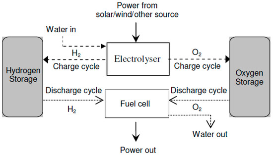 Figure 5. Block diagram of DRFCs.
Furthermore, DRFCs offer the capability to halt the flow of water, enabling the return of water to the electrolyzer’s water storage when operating in fuel cell mode. This feature holds significant value for installations in space, aircraft, or underwater applications where water recycling is necessary. Moreover, it proves particularly beneficial for sustainable energy utilization in regions with limited water supply. By optimizing the performance and cost-effectiveness of both the electrolyzer and fuel cells, this research aims to enhance their efficiency. Additionally, the cell’s capacity can be flexibly adjusted in two directions, allowing simultaneous operation in both modes.
- 2.
- Unitized Regenerative Fuel Cell: URFCs, unlike DRFCs, are devices designed with the capability to operate in two modes: E (electrolyzer) mode and FC (fuel cell) mode. In contrast to DRFCs, URFCs utilize a single physical cell, as depicted in Figure 6 that serves both as an electrolyzer and a fuel cell. The fundamental electrochemical reaction of this reversible bi-functional unit is represented by Equation (1). While in FC mode, the released heat and power from the reaction of hydrogen and oxygen gases are used to regenerate water, whereas URFCs enable the conversion of water into hydrogen and oxygen in E-mode [26].
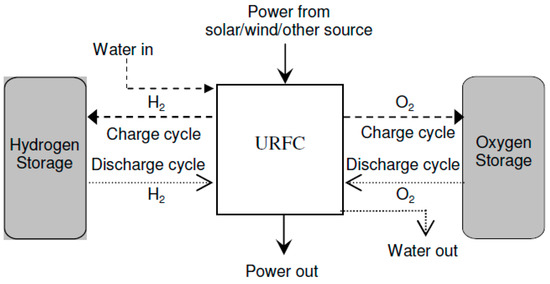 Figure 6. Block diagram of URFCs.
URFCs often start off in E-mode, which is where the processing of hydrogen and oxygen takes place. Then, for FC-mode operation, these gases are taken out and put back in the same unit. Water is supplied by flow fields in E-mode, where it is electrolyzed into oxygen and hydrogen under the influence of the applied voltage during cell loading and catalyst activity. Water interacts with the catalyst to release protons and electrons. Positively charged ions (Protons) are attracted toward the cathode and travel through the ion exchange membrane whereas negatively charged ions (electrons) travel towards the other end of the cell through an electric circuit. At the cathode, electrons combine with hydrogen protons to form a stabilized atom of hydrogen.
The half-cell processes observed in E-mode are represented by Equations (2)–(4):
Anode’s chemical reaction is represented in Equation (2):
H2O → 2H+ + 2 e− + ½ O2.
Cathode’s chemical reaction is represented in Equation (3):
2H+ + 2 e−→ 2H2.
The overall electrochemical reaction is shown in Equation (4):
H2O → H2 + ½ O2.
The processes of hydrogen oxidation and oxygen reduction take place in FC-mode operation [27], as illustrated by Equations (5)–(7):
Anode’s chemical reaction is represented in (5):
H2 → 2 H+ + 2 e−.
Cathode’s chemical reaction is represented in Equation (6):
½ O2 + 2 e− +2 H+→ H2O.
The overall electrochemical reaction is shown in Equation (7):
H2 + ½ O2 → H2O.
URFCs possess the ability to serve as a backup battery by transforming electrical energy into chemical energy while being charged. When in discharge mode, the URFCs device functions as a fuel cell, directly converting the stored reactants into electricity [28].
2.2. Focus on PEM for URFCS
There is a significant emphasis on proton exchange membranes (PEMs) in the development of URFCs. The majority of URFCs utilize solid polymer PEMs as their electrolyte [29,30,31,32]. The invention of PEMs can be attributed to Willard Thomas Grubb and Lee Niedrach, who made the breakthrough in the early 1960s. These solid fluoro polymer membranes are chemically modified and incorporate sulfonic acid groups, which readily release hydrogen protons [33], as depicted in Equation (8).
SO3H → SO3− + H+.
The ionic model employed in proton exchange membranes (PEMs) enables the permeation of water through the membrane while preventing the production of hydrogen and oxygen gases. Consequently, the water protons in the form of hydronium (H3O+) are able to move freely, while the SO3H groups remain stable within the polymer side chains. When an electric field is applied to the membrane, the water protons are drawn towards the negatively charged electrode. This unique behavior of the membrane, acting as a conductor for power transfer, classifies it as a proton conductor.
2.3. Basic Types of URFCs
Figure 7 represents the flow chart of various types of conventional URFCs and the details of these URFCs are illustrated below:
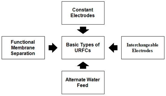
Figure 7.
Flow chart of URFCs Types.
- 1.
- Constant Electrode Type:
In the prevalent configurations of URFCs, as depicted in Figure 8, the electrode responsible for hydrogen production and consumption during E mode is commonly referred to as the “hydrogen electrode”. Conversely, the other electrode is involved in the formation and absorption of oxygen, earning the designation of “oxygen electrode”. These electrodes permit the passage of current in both modes by serving as the cathode and anode. For this type of URFCs, the terms oxygen and hydrogen electrodes are used in the present work instead of “cathode and anode”, and to avoid confusion.
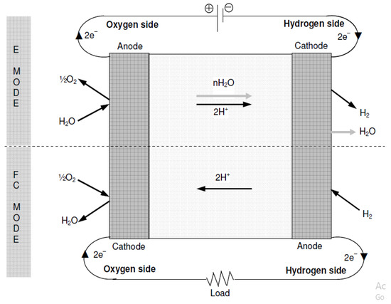
Figure 8.
Basic Diagram of Constant Electrodes.
In FC mode, it is necessary to support the opposite reaction of water formation. Therefore, the catalyst layer must work bi-functional. The development of URFCs requires addressing the crucial challenge of achieving bi-functionality since most catalysts exhibit a preference for one-way reactions and lack effectiveness in reverse reactions [34].
The hydrogen electro-catalyst layer must withstand the hydrogen formation reaction in E mode (refer to Equation (3) above) and the inverse separation of hydrogen molecules in FC mode. Fortunately, platinum serves as an effective catalyst for both the formation reaction and the splitting of hydrogen molecules, necessitating the catalyst layer to be bi-functional once more. Therefore, the basic design and cross-sectional problems of the material tend to achieve the double-function/bi-functionality of an oxygen electrode in terms of catalytic efficiency and reaction rate, rather than the hydrogen side. In addition, the formation reactions and water-splitting involve a series of intermediate reactions [35], which are much more complex than hydrogen side reactions. However, during E-mode, the generated oxygen combines with water vapors and is carried along, as illustrated in Figure 8.
- 2.
- Interchangeable Electrodes:
The alternative properties of URFCs converts electrode that come into contact with oxygen and hydrogen and vary from method to method as shown in Figure 9. In this type of fuel cell, oxidation takes place both in the oxidation reaction (electron consumption), and in the reduction reaction (electron generation) by the same electrode (cathode). According to claims, in comparison to the initial category of URFCs mentioned in the preceding subsection, it was relatively simpler to identify a suitable catalyst and establish a stable electrode for this particular type. In particular, the utilization of platinum on both electrodes within the catalyst layer has proven effective in promoting the decomposition reaction at one electrode during E-mode and facilitating the formation of hydrogen at the other electrode during FC mode. However, catalytic materials can be applied to both electrodes in order to avoid water formation reactions. Thus, the two electrodes contain a mixture of catalysts, for the first type of URFCs rather than a single electrode.
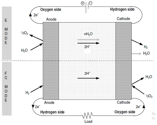
Figure 9.
Basic Diagram of Interchangeable Electrodes.
Another limitation of utilizing this method of electrode switching is the possibility of oxygen and hydrogen intermingling on both sides of the membrane. This mixing can lower the cell’s efficiency and raise safety concerns if the oxygen–hydrogen mixture exceeds its flammability limit. To address this problem, it is usually essential to flush the electrode region with an inert gas like nitrogen while transitioning modes to avoid any undesired mixing.
- 3.
- Alternate Water Feed:
Both of the mentioned design types involve the introduction of water into URFCs during E-mode, specifically at the oxygen electrode. However, there is an alternative approach where water is supplied to the hydrogen electrode, referred to as cathode feed. This method relies on the diffusion of water molecules through the membrane to supply water for the oxygen electrode’s water-splitting reaction, as shown in Figure 10. The benefit of this water supply method is that a single-phase separator on the hydrogen side is adequate for separating hydrogen gas from hydrogen vapor, since water is predominantly present in significant amounts at the hydrogen electrode [36]. At high current concentrations, the oxygen fraction is easy to dry, and the electrolysis reaction is suppressed. If water is supplied with oxygen, this part of the water is always high, and it cannot be drained.
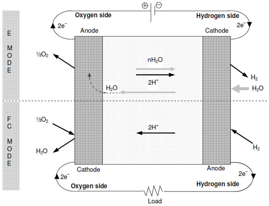
Figure 10.
Basic Diagram of Alternate Feed Water.
- 4.
- Functional Membrane Separation:
Another type of URFC proposed by [37] separates the field with a single membrane from one part of the water-electrolyte and another part of the FC mode. Each channel supplies gas and water on both sides.
3. Operational Modes of URFCs
The basic operational modes of the unitised regenerative fuel cell are classified into two types, i.e., Electrolyzer mode and Fuel Cell mode. In these two types of operational modes, the URFCs operate and these both operational modes are illustrated below in detail:
- Electrolyzer-Mode Operation of URFCs:
In E-mode operation, the oxygen side of the cell is supplied with water while being connected to the positive terminal of a suitable DC power supply. The chemical reaction involved in oxygen production is represented by Equation (2). The protons generated from water splitting traverse a proton-conductive polymer-based membrane. Equation (3) illustrates the reduction of protons at the hydrogen side connected to the anode, resulting in the production of hydrogen. Figure 11 presents a concise process diagram demonstrating the flow of reactants, materials, and energy during the electrolysis process of URFCs.
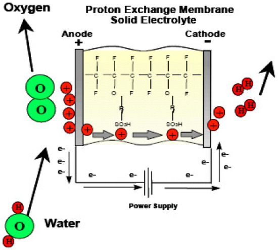
Figure 11.
Basic Diagram of E-mode in URFCs.
In Equation (4), the endothermic reaction energy charge is described. The theoretical energy requirement associated with the corresponding thermodynamic reaction is depicted in Equation (9):
∆H = ∆G + T∆S.
In the provided equations, ∆H represents the enthalpy change, ∆G represents the variation in Gibbs free energy, T represents the absolute temperature, and ∆S signifies the change in entropy [38]. The change in Gibbs free energy (∆G) specifically refers to the energy required in the form of electricity for water electrolysis. Conversely, the term “T∆S” refers to the energy of the reaction that can potentially be supplied thermodynamically through thermal energy.
The change in Gibbs free energy at standard conditions (NTP) is represented by Equation (10) [39]:
∆G = 237.2 kJ/mol.
Electricity serves as the primary energy source in real-world scenarios, accounting for factors like low-temperature electrolysis (e.g., 80 °C) and different forms of energy loss. The effect of these inefficiencies is to melt/dissipate the remaining heat. However, high temperature can provide the necessary energy to affect electrolysis at high temperature [40,41].
- 2.
- Fuel Cell Mode Operation of URFCs
URFCs produce energy in FC mode by introducing hydrogen gas on the H side and oxygen gas on the O side, as illustrated in Figure 12. The chemical reaction that takes place releases energy, which is referred to as Gibbs free energy. This may be described as the discrepancy between the reactant and product energies of the Gibbs free energy process.
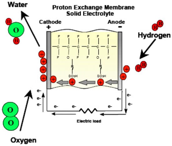
Figure 12.
Basic Diagram of FC-mode in URFCs.
In FC mode, the Gibbs free energy change is negative, indicating an exothermic reaction, while in E mode, it is positive, indicating an endothermic reaction, as shown in Equation (11) [42]:
∆Gf = ∆Gf (products) − ∆Gf (reactants).
The usual expression for Gibbs free energy is on a per mole basis. Hence, by substituting Gf with gf in the equation for the overall cell reaction, we obtain in Equation (12):
The Gibbs free forming energy in Equation (11), which is not constant and varies with temperature and state, can be calculated using Equation (13) at 80 °C:
∆gf = −228.2 kJ/mol.
The presence of the negative sign signifies the exothermic nature of the direct water-forming process. The electrical work performed corresponds to the Gibbs free energy of formation [43], as shown in Equations (14) and (15) for an ideal system without losses:
The standard electrode potential or reversal voltage of a hydrogen fuel cell can be determined using these equations. The magnitude of E is influenced by the temperature and pressure conditions that regulate the formation of free energy. For an H2/O2 fuel cell, the open voltage is 1.229 V at 25 °C and atmospheric pressure.
3.1. Limitations and Areas Requiring Research & Development
URFCs have a variety of potential applications from the same cell in both FC and E modes to store electricity for a relatively long time and rehabilitate it if necessary. The economic benefit over electrodes and special fuel cell systems in terms of volume and mass is the size of the functional cells in each mode which can be sustained at a point similar to the corresponding output/efficiency of both electrolyzer and fuel cells. So far, the most effective laboratory PEMURFCs have an energy recovery efficiency of 30–38%. URFCs with up to 45% energy efficiency must be technologically feasible in the near future. Probably the necessary goal of increasing energy efficiency by more than 50% through the return of energy will not only require improved URFCs designs but also progress in the development of PEM cells (or others).
The URFCs system obviously offers a combination of heat and energy, which indicates that there are suitable applications that require low-temperature heat nearby. Despite lower average capital costs than electrolyzers and advanced fuel cell systems, URFCs despite equivalent efficiency aim to make hydrogen storage systems more efficient in terms of economics similar to alternatives like batteries. Batteries have better energy efficiency (up to 75%) than short-term hydrogen systems, but automatic discharges with longer storage times tend to have a relatively rapid drop in energy efficiency.
3.2. Technological Challenges on URFCs
There are broadly three identified technical hurdles facing the widespread acceptance of URFCs as shown in Figure 13. In this technical challenge, the structural setup of a stack is further classified into three categories as shown in the diagram.
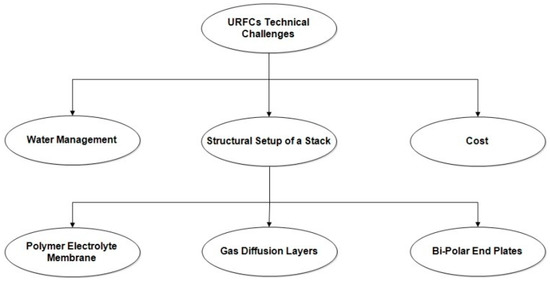
Figure 13.
URFCs technological challenges.
- Water Management:
The electrodes of URFCs are so designed to intentionally flood the oxygen side in E-mode operation. Instead, for FC-mode operation electrodes are designed to increase the mobility of H2 and O2 and supply water that reaches the catalyst surface. The [44,45] concluded that parallel BPP flow design and double counting improve fuel cell efficiency and electrolysis. The author believed that GDL was treated with PTFE for oxygen electrodes. This helps to improve drainage in FC mode.
- 2.
- Cost:
The main drawback of the URFC system is the high expensive of components used. High costs are associated with the use of rare platinum (Pt) in bi-functional electro-catalysts and the high cost of polymer electrolytes in the cellular domain [46,47]. Figure 14 shows the study of the fuel cell cost status for 500,000 systems per year relative to the projected costs for 2020. It reveals that URFCs device technology advancement enables the use of diverse materials to reduce costs.
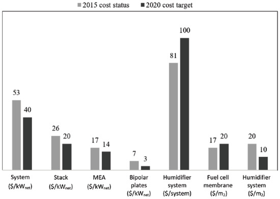
Figure 14.
Projected cost of a fuel cell system in USD [48].
- 3.
- Structural Setup of URFCs StackThe structural setup of a typical URFCs stack comprises the following components:
- (a)
- A polymer electrolyte membrane (PEM)
- (b)
- Gas diffusion layers (GDLs)
- (c)
- Bi-polar end plates with flow channels
Nafion-117, which is extensively utilized as a proton exchange membrane (PEM) in hydrogen fuel cells, demonstrates remarkable proton conductivity and negligible gas permeation [49]. Acting as both a fuel and electron barrier, the conductive polymer membrane of Nafion prevents electrode dissolution and functions as a proton conductor [50]. However, Nafion is expensive at high temperatures and low humidity, and its performance is not optimal. Hydrocarbon-based PEMs offer increased proton conductivity but are prone to water flooding. Therefore, an ideal approach involves integrating PEMs that combine high mechanical properties with proton conductivity.
The gas diffusion layer (GDL) serves multiple functions, such as enabling the movement of reactive gases from the flow channel to the catalyst layer, directing water away from the catalyst layer towards the flow channel, and ensuring stable moisture levels within the membrane [51,52]. Bipolar plates play a crucial role in distributing the oxidant and fuel throughout the cell, managing water within the cell, isolating individual cells within the stack, and carrying current away from the cell.
4. Solar Hydrogen Renewable Energy System Applications in RAPS
Solar hydrogen renewable energy systems along with other renewable energy sources, decentralized generation, hydrogen storage on site, and recirculation of hydrogen stored in fully contained fuel cells allow energy to be loaded without interruption. The solar hydrogen system is one of the most prominent evolving sustainable energy technologies that can replace fossil fuels and minimize the effects of global warming. Hydrogen solar systems are very suitable for powering remote applications because they are completely independency of grids or any kind of backup source based on fossil fuels. Low impact on the environment and high reliability are several potential benefits over traditional battery or diesel systems. Around 2 billion people worldwide do not have access to electricity. Due to the high cost of fossil fuel transportation, the connection to the main power grid involves high cost and therefore, the solar hydrogen system presents market prospects for off-grid applications in the RAPS system.
Hydrogen can be produced using basic sources and technical opportunities, namely coal gasification, natural gas recovery, and water-based nuclear energy. Renewable energy has many benefits for stabilizing hydrogen production like low net greenhouse gas emissions. Power needs and consumer capacity in the RAPS system vary according to location. Figure 15 illustrates the concept of using renewable energy hydrogen in the remote area. Other types of hydrogen storage materials are under investigation, such as metal hydride and carbon nano-tubes [53]. Hydrogen and oxygen are injected into the fuel cell that generates power even when the house needs heating when solar energy is not available. To address the needs of families, numerous 1.5 kW to 250 kW pilot and experimental solar hydrogen RAPS systems have been created. This is a reliable method, and it has been shown to be effective. PEM is also increasingly used in electrical applications of RAPS. Several simulations of the solar hydrogen renewable energy system have been outlined in the literature.
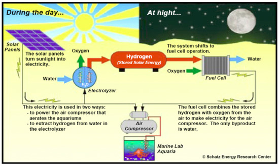
Figure 15.
Solar hydrogen system schematic.
4.1. Benefits and Challenges Facing Solar Hydrogen Renewable Energy System RAPS
4.1.1. Benefits of Solar Hydrogen Renewable Energy System in RAPS
Solar hydrogen renewable energy systems in RAPS offer several benefits that make them a promising and sustainable energy solution. Some of the key benefits include:
- Renewable and clean energy: Solar hydrogen renewable energy systems harness solar energy, a renewable, and abundant source of power. By converting sunlight into hydrogen through electrolysis, these systems provide clean energy without greenhouse gas emissions or air pollution. This contributes to reducing the carbon footprint and mitigating climate change.
- Energy independence: RAPS often rely on diesel generators or other fossil fuel-based power sources, which are expensive and require fuel transportation. Solar hydrogen renewable energy systems offer a way to reduce dependence on fossil fuels and enable energy independence. The solar energy captured and stored as hydrogen can be used to meet energy demands, reducing the need for external fuel supply and associated costs.
- Energy storage and dispatchability: One advantage of solar hydrogen renewable energy systems is the storage system of energy which can be utilized later. Hydrogen can be stored for an extended period, allowing for dispatchability and continuous power supply even when sunlight is unavailable. This energy storage capability is crucial for RAPS, which often face intermittent energy generation and varying energy demand patterns.
- Scalability and modularity: Solar hydrogen renewable energy systems can be designed to be scalable and modular, making them suitable for diverse energy needs in remote areas. Depending on the energy demand, the generation capacity of the system can be adjusted by adding or reducing the solar panels and electrolysis units. This flexibility allows for cost-effective customization and expansion based on the specific requirements of the community.
- Reduced operational costs: Once the solar hydrogen renewable energy system is set up, the operational costs can be lower compared to traditional diesel generators. Solar energy is free and abundant, and the cost of hydrogen production from electrolysis is becoming more competitive. With proper maintenance, operational costs can be significantly reduced, leading to long-term cost savings.
- Environmental benefits: Solar hydrogen renewable energy systems contribute to environmental preservation in remote areas. By replacing diesel generators, they reduce noise pollution, air pollution, and carbon emissions, improving the quality of air and overall environmental conditions. This is particularly beneficial in ecologically sensitive areas and regions where reliance on fossil fuels can have detrimental effects on the local ecosystem.
- Community development and empowerment: Implementing solar hydrogen renewable energy systems in RAPS can bring positive socio-economic impacts. It provides opportunities for local employment in system installation, maintenance, and operation. Moreover, access to reliable and clean energy enhances the quality of life, enables educational and healthcare facilities, and supports economic activities in remote communities, fostering sustainable development and empowerment.
Solar hydrogen renewable energy systems offer a viable and sustainable energy solution for RAPS, addressing the energy needs of remote communities while minimizing environmental impact and promoting self-sufficiency. These benefits make solar hydrogen renewable energy systems a promising technology for off-grid areas striving for clean, reliable, and cost-effective energy solutions.
4.1.2. Challenges Facing in Solar Hydrogen Renewable Energy Systems in RAPS
Solar hydrogen renewable energy systems, which combine solar energy with hydrogen production, have the potential to play a significant role in remote area power systems (RAPS). However, there are certain constraints on connecting PEM electrolyzer with solar PV modules, one of which is figuring out the best configuration. This is accomplished by adjusting the MPP of the solar PV modules to the I-V characteristics of the PEM electrolyzer, which is conducted via an inverter acting as a DC-DC converter [54]. However, there are several challenges facing solar hydrogen renewable energy systems in RAPS:
- Cost: The capital cost of setting up solar hydrogen renewable energy systems can be high. The equipment required for solar energy generation, such as solar panels and inverters, as well as the electrolysis equipment for hydrogen production, can be expensive. Additionally, the cost of hydrogen storage and distribution infrastructure adds to the overall cost.
- Efficiency: The conversion efficiency of solar energy to hydrogen is relatively low. Photovoltaic (PV) cells typically have an efficiency of around 15–20%, and electrolysis processes have efficiency losses as well. These inefficiencies result in a lower overall energy conversion efficiency, which affects the economic viability of solar hydrogen renewable energy systems.
- Energy storage: One of the main advantages of hydrogen is its potential for long-term energy storage. However, storing hydrogen in an efficient and safe manner can be challenging. Hydrogen has low energy density, and its storage requires high-pressure tanks or cryogenic conditions, both of which add complexity and cost to the system.
- Scalability: Solar hydrogen renewable energy systems in RAPS need to be scalable to meet varying energy demands. Balancing the intermittent nature of solar energy generation with the continuous energy requirements of a community can be challenging. Adequate storage capacity and effective energy management systems are necessary to ensure reliable power supply.
- Infrastructure and logistics: Establishing a solar hydrogen renewable energy system requires suitable infrastructure for hydrogen production, storage, and distribution. This infrastructure might not be readily available in remote areas, necessitating additional investment and logistical challenges. Transportation of hydrogen to end-users in RAPS can also be a hurdle due to safety considerations.
- Maintenance and operation: Solar hydrogen renewable energy systems require regular maintenance and operation to ensure optimal performance. This can be particularly challenging in remote areas where skilled personnel and spare parts may not be readily accessible. Adequate training and support systems are crucial to address these challenges.
- Regulatory and policy framework: The regulatory and policy environment plays a significant role in the adoption of solar hydrogen renewable energy systems. In some cases, outdated regulations or a lack of supportive policies can hinder the deployment of these systems. Clear guidelines, incentives, and frameworks that support renewable energy and hydrogen technologies are necessary to foster their growth in RAPS.
Despite these challenges, ongoing research and technological advancements are addressing many of these issues. Improvements in solar cell efficiency, electrolysis technologies, energy storage methods, and supportive policies can enhance the viability and effectiveness of solar hydrogen renewable energy systems in RAPS.
5. Future Research Directions
Future research directions for solar hydrogen renewable energy systems in RAPS can focus on addressing the existing challenges and further enhancing the performance and feasibility of these systems. Some potential research directions include:
- Efficiency improvements: Research efforts can be directed towards improving the efficiency during solar energy conversion and also during electrolysis processes. Developing advanced photovoltaic technologies with higher conversion efficiencies and exploring novel catalysts for electrolysis can contribute to overall system efficiency improvements.
- Energy storage technologies: Investigating alternative and more efficient methods for hydrogen storage can be a fruitful area of research. Research can focus on developing materials with higher hydrogen storage capacity, exploring advanced compression and liquefaction techniques, and investigating solid-state hydrogen storage technologies.
- Hybrid systems: Integrating solar hydrogen renewable energy systems with other renewable energy sources, such as wind or biomass, can enhance system reliability and efficiency. Research can explore the design and optimization of hybrid systems that combine multiple energy sources to overcome the intermittent nature of solar energy and ensure a continuous power supply.
- System modeling and optimization: Developing advanced modeling and optimization tools can assist in designing and operating solar hydrogen renewable energy systems in RAPS. Research can focus on creating accurate models that incorporate various system components, energy flows, and storage dynamics. Optimization algorithms can then be applied to maximize system performance, considering factors like energy demand, solar availability, and storage capacity.
- Techno-economic analysis: Conducting comprehensive techno-economic analyses of solar hydrogen renewable energy systems in RAPS can provide valuable insights for system deployment. Research might concentrate on determining how to reduce the overall cost of the system, taking into consideration capital expenditure, operating and maintenance expenses, and the levelized cost of hydrogen production. This research can point out cost-cutting measures and show how economically viable solar hydrogen renewable energy systems are in various RAPS scenarios.
- Remote monitoring and control: Developing remote monitoring and control systems can enable efficient operation and maintenance of solar hydrogen renewable energy systems in remote areas. Research can explore the use of IoT (Internet of Things) technologies, data analytics, and machine learning algorithms to remotely monitor system performance, detect faults, and optimize operation strategies.
- Policy and regulatory frameworks: Research can focus on analyzing the impact of policies and regulations on the deployment of solar hydrogen renewable energy systems in RAPS. Assessing the effectiveness of existing policies and identifying barriers to deployment can help shape supportive frameworks that incentivize renewable energy and hydrogen technologies in off-grid communities.
By pursuing these research directions, the understanding and implementation of solar hydrogen renewable energy systems in RAPS can be significantly advanced, leading to more efficient and sustainable energy [55,56,57,58,59] solutions for remote areas.
6. Conclusions
In the upcoming future, URFCs play a vital role in alternative energy systems because of their high energy density. This manuscript provides a comprehensive review of URFCs in the context of remote area power supply. The review covers various aspects such as the historical background, current status, operating modes, types of URFCs, technical challenges in R&D, and the role and application of solar hydrogen renewable energy in remote area power supply systems. The manuscript also discusses the benefits and challenges associated with implementing solar hydrogen renewable energy solutions in remote areas. Renewable hydrogen systems have great potential in the market of RAPS systems, primarily because conventional energy sources tend to be expensive in such areas. In this context, URFCs present a promising opportunity for cost savings in solar hydrogen power supply systems designed for remote locations. By integrating the functionalities of an electrolyzer and a fuel cell into a single device, URFCs eliminate the need to purchase separate and expensive electrolyzer and fuel cell units. Overall, this manuscript sheds light on the significance of URFCs in remote area power supply and highlights the potential economic benefits they bring to solar hydrogen renewable energy systems in such settings.
Author Contributions
Conceptualization, M.K.S., J.G. and P.N.; methodology, M.K.S., J.G. and A.S.O.; resources, M.K.S., M.H.A. and A.J.; data curation, A.J. and M.H.A.; writing—original draft preparation, M.K.S. and J.G.; writing—review and editing, P.N., A.S.O., M.H.A. and A.J. All authors have read and agreed to the published version of the manuscript.
Funding
This research received no external funding.
Data Availability Statement
Not applicable.
Conflicts of Interest
The authors declare no conflict of interest.
References
- Khan, M.J.; Iqbal, M.T. Pre-feasibility study of stand-alone hybrid energy systems for applications in Newfoundland. Renew. Energy 2005, 30, 835–854. [Google Scholar] [CrossRef]
- Alsharif, M.H. A Solar Energy Solution for Sustainable Third Generation Mobile Networks. Energies 2017, 10, 429. [Google Scholar] [CrossRef]
- Donis, M.; Roberto, W. Apparatus for Integrated Water Deionization, Electrolytic Hydrogen Production, and Electrochemical Power Generation. U.S. Patent 6,569,298, 27 May 2003. [Google Scholar]
- Alsharif, M.H.; Kim, J. Optimal Solar Power System for Remote Telecommunication Base Stations: A Case Study Based on the Characteristics of South Korea’s Solar Radiation Exposure. Sustainability 2016, 8, 942. [Google Scholar] [CrossRef]
- Alsharif, M.H.; Kim, J.; Kim, J.H. Opportunities and Challenges of Solar and Wind Energy in South Korea: A Review. Sustainability 2018, 10, 1822. [Google Scholar] [CrossRef]
- Alsharif, M.H.; Kim, J. Hybrid Off-Grid SPV/WTG Power System for Remote Cellular Base Stations Towards Green and Sustainable Cellular Networks in South Korea. Energies 2017, 10, 9. [Google Scholar] [CrossRef]
- Bockris, J.O.M.; Veziroglu, T.N. Solar Hydrogen Energy; MacDonald Optima: London, UK, 1991. [Google Scholar]
- Elam, C.C.; Padr, C.E.G.; Sandrock, G.; Luzzi, A.; Lindblad, P.; Hagene, E.F. Realizing the hydrogen future: The International Energy Agency’s efforts to advance hydrogen energy technologies. Int. J. Hydrogen Energy 2003, 28, 601–607. [Google Scholar] [CrossRef]
- Marshall, A.; Borresen, B.; Hagen, G.; Tsypkin, M.; Tunold, R. Hydrogen production by advanced proton exchange membrane (PEM) water electrolysers—Reduced energy consumption by improved electro catalysis. Energy 2007, 32, 431–436. [Google Scholar] [CrossRef]
- G8 Information Centre. G8 Renewable Energy Task Force, Final Report, July 2001. 2001. Available online: http://www.g7.utoronto.ca/meetings-official/g8renewables_annex.pdf (accessed on 14 June 2008).
- Moseley, P.T. Energy storage in remote area power supply (RAPS) systems. J. Power Sources 2006, 155, 83–87. [Google Scholar] [CrossRef]
- Al-Badi, A.H. Pre-feasibility study of stand-alone hybrid energy systems for applications in eco-houses. Int. J. Sustain. Eng. 2013, 6, 48–54. [Google Scholar] [CrossRef]
- Aurora, P.H. Modelling & Control of a Solar Hydrogen Fuel Cell System for Remote Applications. Master’s Thesis, University of Massachusetts, Amherst, MA, USA, 2003. [Google Scholar]
- Dutton, A.G.; Bleijs, J.A.M.; Dienhart, H.; Falchetta, M.; Hug, W.; Prischich, D.; Ruddell, A.J. Experience in the design, sizing, economics, and implementation of autonomous wind-powered hydrogen production systems. Int. J. Hydrogen Energy 2000, 25, 705–722. [Google Scholar] [CrossRef]
- Pettersson, J.; Ramsey, B.; Harrison, D. A review of the latest developments in electrodes for unitised regenerative polymer electrolyte fuel cells. J. Power Sources 2006, 157, 28–34. [Google Scholar] [CrossRef]
- Mitlitsky, F.; Myers, B.; Weisberg, A.H.; Molter, T.M.; Smith, W.F. Reversible (Unitized) PEM Fuel Cell Devices. In Proceedings of the Portable Fuel Cells Conference, Lucerne, Switzerland, 21–24 June 1999. [Google Scholar]
- Smith, W. The role of fuel cells in energy storage. J. Power Sources 2000, 86, 74–83. [Google Scholar] [CrossRef]
- Mitlitsky, F.; Groot, W.; Butler, L.; McElroy, J. Integrated Modular Propulsion and Regenerative Electro-Energy Storage System (IMPRESS) For Small Satellites. In Proceedings of the 10th Annual American Institute of Aeronautics and Astronautics/Utah State University Conference, Logan, UT, USA, 16–20 September 1996. [Google Scholar]
- Ogbonnaya, C.; Abeykoon, C.; Nasser, A.; Turan, A. Unitized regenerative proton exchange membrane fuel cell system for renewable power and hydrogen generation: Modelling, simulation, and a case study. Clean. Eng. Technol. 2021, 4, 100241. [Google Scholar] [CrossRef]
- Mitlitsky, F.; Myers, B.; Weisberg, A.H. Lightweight Pressure Vessels and Unitized Regenerative Fuel Cells. In Proceedings of the Fuel Cell Seminar, Kissimmee, FL, USA, 17–20 November 1996. [Google Scholar]
- Frank, D.G. The Effects of Cell Design and Materials of Construction on the Electrolysis Performance of a Proton Exchange Membrane Unitized Regenerative Fuel Cell. Master’s Thesis, University of Toronto, Toronto, ON, Canada, 2000. [Google Scholar]
- Mitlitsky, F.; Myers, B.; Weisberg, A.H. Regenerative Fuel Systems R & D. In Proceedings of the U.S. DOE Hydrogen Program Review, Arlington, VA, USA, 28–30 April 1998. [Google Scholar]
- Andrews, J. The Transition to Hydrogen Energy (Renewable-Energy Hydrogen Systems for Remote Area Power Supply). Ph.D. Thesis, RMIT University, Melbourne, Australia, 2005. [Google Scholar]
- Doddathimmaiah, A.K.; Andrews, J. The use of PEM unitised regenerative fuel cells in solar- hydrogen systems for remote area power supply. In Proceedings of the 16th World Hydrogen Energy Conference, Lyon, France, 12–14 June 2006. [Google Scholar]
- Yao, W.; Yang, J.; Wang, J.; Nuli, Y. Chemical deposition of Platinum nanoparticles on Iridium oxide for Oxygen Electrode of Unitized Regenerative Fuel Cell. Electrochem. Commun. 2007, 9, 1029–1034. [Google Scholar] [CrossRef]
- Coalson, R.R., Jr. Unitized Regenerative Fuel Cells (URFC); Opportunities and Limitations in the Fields of Space Propulsion and Energy Storage. Master’s Thesis, University of Colorado, Boulder, CL, USA, 1998. [Google Scholar]
- Ioroi, T.; Kitazawa, N.; Yasuda, K.; Yamamoto, Y.; Takenaka, H. IrO2 deposited Pt electrocatalysts for unitized regenerative polymer electrolyte fuel cells. J. Appl. Electrochem. 2001, 31, 1179–1183. [Google Scholar] [CrossRef]
- Jorissen, L. Bifunctional oxygen/air electrodes. J. Power Sources 2006, 155, 23–32. [Google Scholar] [CrossRef]
- Nijhawan, P.; Singla, M.K.; Gupta, J. A Proposed Hybrid Model for Electric Power Generation: A Case Study of Rajasthan, India. IETE J. Res. 2021, 69, 1952–1962. [Google Scholar] [CrossRef]
- Singla, M.K.; Oberoi, A.S.; Nijhawan, P. Trends so far in Hydrogen Fuel Technology: State of the art. Int. J. Adv. Trends Comput. Sci. Eng. 2019, 4, 1146–1155. [Google Scholar] [CrossRef]
- Singla, M.K.; Oberoi, A.S.; Nijhawan, P. Solar-PV & Fuel Cell based Hybrid Power Solution for Remote Locations. Int. J. Eng. Adv. Technol. 2019, 9, 861–867. [Google Scholar]
- Singla, M.K.; Nijhawan, P.; Oberoi, A.S. Hydrogen fuel and fuel cell technology for 61a cleaner future: 61a review. Environ. Sci. Pollut. Res. 2021, 28, 15607–15626. [Google Scholar] [CrossRef]
- Katukota, S. Computational Modeling of Proton Exchange Membrane Electrolysis Cell for Hydrogen Production. Master’s Thesis, University of Nevada, Las Vegas, NV, USA, 2006. [Google Scholar]
- Murphy, O.J.; Cisar, A.J.; Gonzalez-Martin, A.; Salinas, C.E.; Simpson, S.F. A Novel Unitized Regenerative Proton Exchange Membrane Fuel Cell. Space Electrochem. Res. Technol. NASA Conf. Publ. 1995, 3337, 83–99. [Google Scholar]
- O’Hayre, R.; Cha, S.W.; Colella, W.; Prinz, F.B. Fuel Cell Fundamentals; Wiley & Sons: New York, NY, USA, 2005. [Google Scholar]
- Mitlitsky, F.; Myers, B.; Weisberg, A.H. Regenerative Fuel Cell Systems. Energy Fuels 1998, 12, 56–71. [Google Scholar] [CrossRef]
- Ito, Y.; Takai, Y.; Ishikawa, T. Suzuki Motor Corporation Fuel Cell. U.S. Patent 6,926,982, 9 August 2005. [Google Scholar]
- Norbeck, J.M.; Heffel, J.W.; Durbin, T.D.; Tabbara, B.; Bowden, J.M.; Montano, M. Hydrogen Production in Hydrogen Fuel for Surface Transportation; Society of Automotive Engineers, Inc.: Warrendale, PA, USA, 1996. [Google Scholar]
- Larminie, J.; Dicks, A. Fuel Cells Systems, Explained, 2nd ed.; John Wiley & Sons: England, UK, 2003. [Google Scholar]
- Richard, S.P. A Techno-Economic Analysis of Decentralized Electrolytic Hydrogen Production for Fuel Cell Vehicles. Master’s Thesis, University of Victoria, London, UK, 2004. [Google Scholar]
- Noyes Data Corporation. Hydrogen Manufacture by Electrolysis. Thermal Decomposition and Unusual Techniques; Casper, M.S., Park, R., Eds.; Noyes Data Corporation: New Jersey, NJ, USA, 1978. [Google Scholar]
- Farret, F.A.; Simoes, M.G. Power plants with fuel cells. In Integration of Alternate Sources of Energy; John Wiley & Sons: Chichester, UK, 2006. [Google Scholar]
- Guha. Materials Development for PEM Fuel Cells. Ph.D. Thesis, Case Western Reserve University, Cleveland, OH, USA, 2007. [Google Scholar]
- Hwang, C.; Ito, H.; Maeda, T.; Nakano, A.; Kato, A.; Yoshida, T. Flow field design for a polymer electrolyte unitized reversible fuel cell. ECS Trans. 2013, 50, 787–794. [Google Scholar] [CrossRef]
- Hwang, C.M.; Ishida, M.; Ito, H.; Maeda, T.; Nakano, A.; Kato, A.; Yoshida, T. Effect of titanium powder loading in gas diffusion layer of a polymer electrolyte unitized reversible fuel cell. J. Power Sources 2012, 202, 108–113. [Google Scholar] [CrossRef]
- Ebrahimi, S.; Roshandel, R.; Vijayaraghavan, K. Power density optimization of PEMFC cathode with non-uniform catalyst layer by Simplex method and numerical simulation. Int. J. Hydrogen Energy 2016, 41, 22260–22273. [Google Scholar] [CrossRef]
- Fuentes, R.E.; Colón-Mercado, H.R.; Martínez-Rodríguez, M.J. Pt-Ir/TiCelectrocatalysts for PEM fuel cell/ electrolyzer process. J. Electrochem. Soc. 2014, 161, 77–82. [Google Scholar] [CrossRef]
- Marcinkoski, J.; Spendelow, J.; Wilson, A.; Papageorgopoulos, D. DOE Hydrogen and Fuel Cells Program Record. Available online: https://www.hydrogen.energy.gov/pdfs/15015_fuel_cell_system_cost_2015.pdf (accessed on 28 June 2018).
- Assumma, L.; Nguyen, H.D.; Iojoiu, C.; Lyonnard, S.; Mercier, R.; Espuche, E. Effects of block length and membrane processing conditions on the morphology and properties of per fluoro sulfonated poly (arylene ether sulfone) multiblock copolymer membranes for PEMFC. ACS Appl. Mater. Interfaces 2015, 7, 13808–13820. [Google Scholar] [CrossRef] [PubMed]
- Boutsika, L.G.; Enotiadis, A.; Nicotera, I.; Simari, C.; Charalambopoulou, G.; Giannelis, E.P.; Steriotis, T. Nafion ® nanocomposite membranes with enhanced properties at high temperature and low humidity environments. Int. J. Hydrogen Energy 2016, 41, 22406–22414. [Google Scholar] [CrossRef]
- Won, J.E.; Kwak, D.H.; Han, S.B.; Park, H.S.; Park, J.Y.; Ma, K.B.; Kim, D.H.; Park, K.-W. PtIr/Ti4O7 as a bi-functional electro-catalyst for improved oxygen reduction and oxygen evolution reactions. J. Catal. 2018, 358, 287–294. [Google Scholar] [CrossRef]
- Ye, F.; Xu, C.; Liu, G.; Li, J.; Wang, X.; Du, X.; Lee, J.K. A novel PtRuIr nanoclusters synthesized by selectively electrodepositing Ir on PtRu as highly active bifunctional electrocatalysts for oxygen evolution and reduction. Energy Convers. Manag. 2018, 155, 182–187. [Google Scholar] [CrossRef]
- Barbir, F. PEM electrolysis for production of hydrogen from renewable energy sources. Sol. Energy 2005, 78, 661–669. [Google Scholar] [CrossRef]
- Meda, U.S.; Rajyaguru, Y.V.; Pandey, A. Generation of green hydrogen using self-sustained regenerative fuel cells: Opportunities and challenges. Int. J. Hydrogen Energy 2023, in press. [Google Scholar] [CrossRef]
- Kumar, A.; Sharma, S.; Goyal, N.; Singh, A.; Cheng, X.; Singh, P. Secure and energy-efficient smart building architecture with emerging technology IoT. Comput. Commun. 2021, 176, 207–217. [Google Scholar] [CrossRef]
- Khattar, N.; Sidhu, J.; Singh, J. Toward energy-efficient cloud computing: A survey of dynamic power management and heuristics-based optimization techniques. J. Supercomput. 2019, 75, 4750–4810. [Google Scholar] [CrossRef]
- Alsharif, M.H. Comparative analysis of solar-powered base stations for green mobile networks. Energies 2017, 10, 1208. [Google Scholar] [CrossRef]
- Alsharif, M.H.; Kannadasan, R.; Jahid, A.; Albreem, M.A.; Nebhen, J.; Choi, B.J. Long-term techno-economic analysis of sustainable and zero grid cellular base station. IEEE Access 2021, 9, 54159–54172. [Google Scholar] [CrossRef]
- Alsharif, M.H. Optimization design and economic analysis of energy management strategy based on photovoltaic/energy storage for heterogeneous cellular networks using the HOMER model. Sol. Energy 2017, 147, 133–150. [Google Scholar] [CrossRef]
Disclaimer/Publisher’s Note: The statements, opinions and data contained in all publications are solely those of the individual author(s) and contributor(s) and not of MDPI and/or the editor(s). MDPI and/or the editor(s) disclaim responsibility for any injury to people or property resulting from any ideas, methods, instructions or products referred to in the content. |
© 2023 by the authors. Licensee MDPI, Basel, Switzerland. This article is an open access article distributed under the terms and conditions of the Creative Commons Attribution (CC BY) license (https://creativecommons.org/licenses/by/4.0/).