
Simulation Analysis of Mechanical Fluidized Bed in Adsorption Chillers
 , , , , , and
Abstract
:1. Introduction
- Finned-tube heat exchangers, which consist of a single tube or a multi-tube system of straight or U-shaped tubes that are finned on the outside. The adsorbent is placed between the fins, and the whole is inserted into a special mesh that holds all the components together.
- Plate finned-tube heat exchanger. This heat exchanger consists of longitudinal manifolds connected by smaller diameter tubes forming a meandering ‘finning’ in order to increase the heat transfer surface. The tubes are connected to each other by means of fin plates. The entire heat exchange assembly is placed in a frame with a mesh which prevents the adsorbent from moving freely in the structure. With this exchanger, the device achieved a COP value of 0.48, with SCP from 208 W/kgads to 590 W/kgads [19,20].
- Finned flat-tube heat exchanger is a structure consisting of flattened tubes connected by a dense mesh arranged in alternately overlapping triangular-shaped fins. The spaces between the fins are filled with adsorbent and enclosed in a frame. By using an appropriate granulation, it is possible to achieve a COP of 0.4 with SCP from 675 W/kgads to 2.3 kW/kgads [20].
2. Materials and Methods
2.1. Mathematical Model
- The housing of the elements has been simplified to the form of a cylinder, without sight glasses and measuring connectors.
- Irregularly shaped elements such as heating and cooling junction boxes in the evaporator and condenser are simplified to a cylinder form.
- For the sorption chamber, the structural elements supporting the bed were omitted, and the bed itself was simplified to the form of a cuboid.
- Orthogonal quality: value is in the range <0, 1>, value 1 stands for the highest possible quality.
- Skewness: value is in the range <0, 1>, value 0 stands for the highest possible quality.
2.2. Physical Model
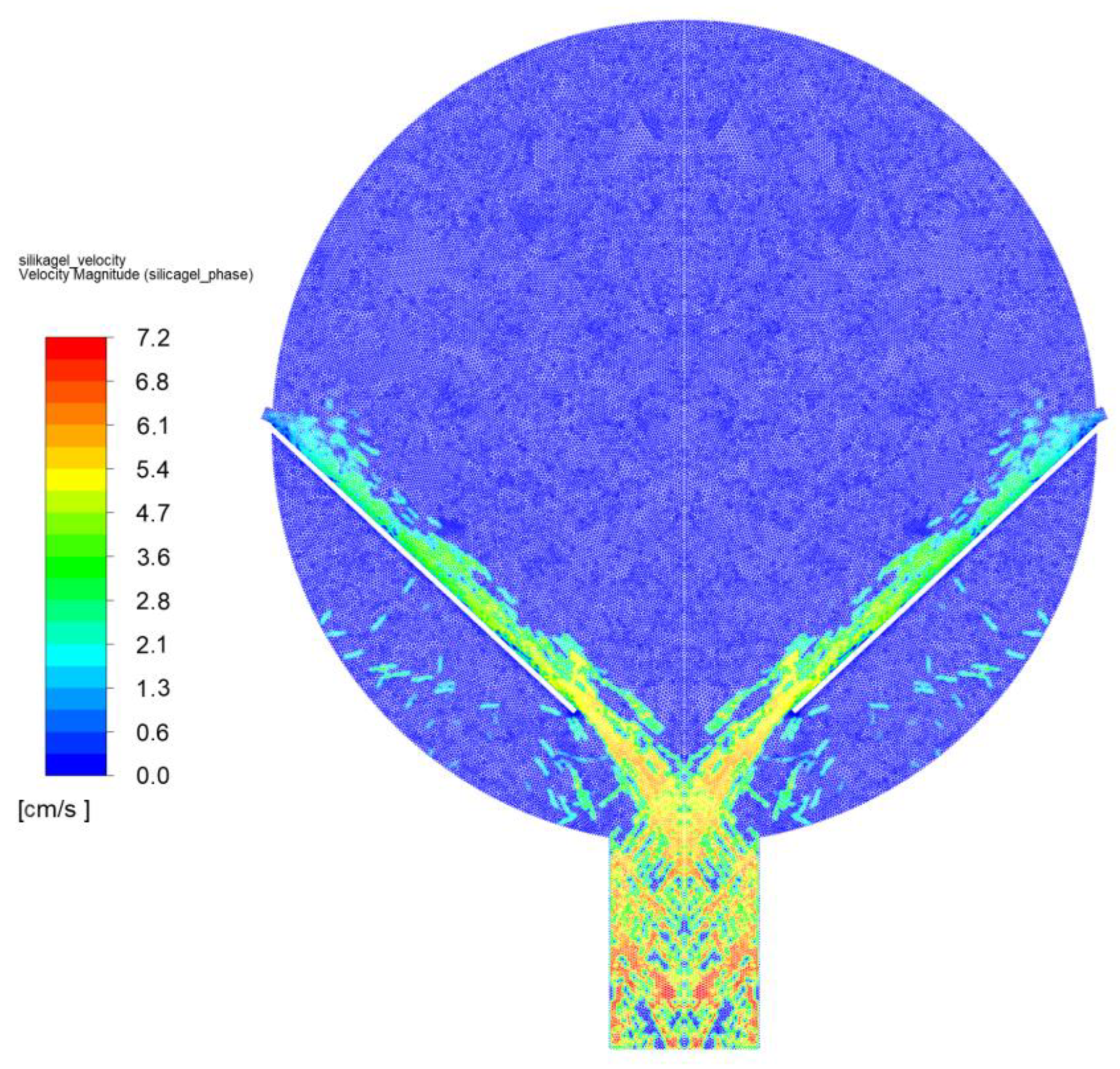
3. Results—Model of CFD Fluidized Mechanical Bed
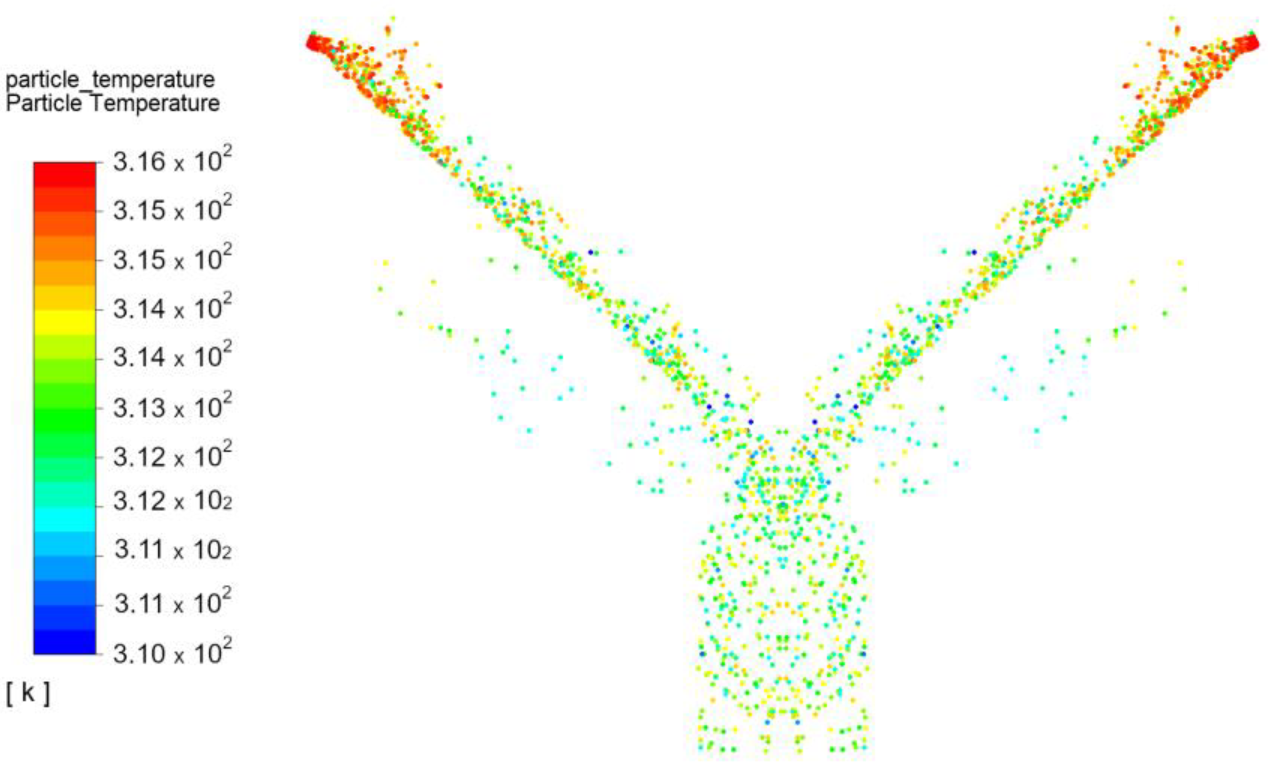
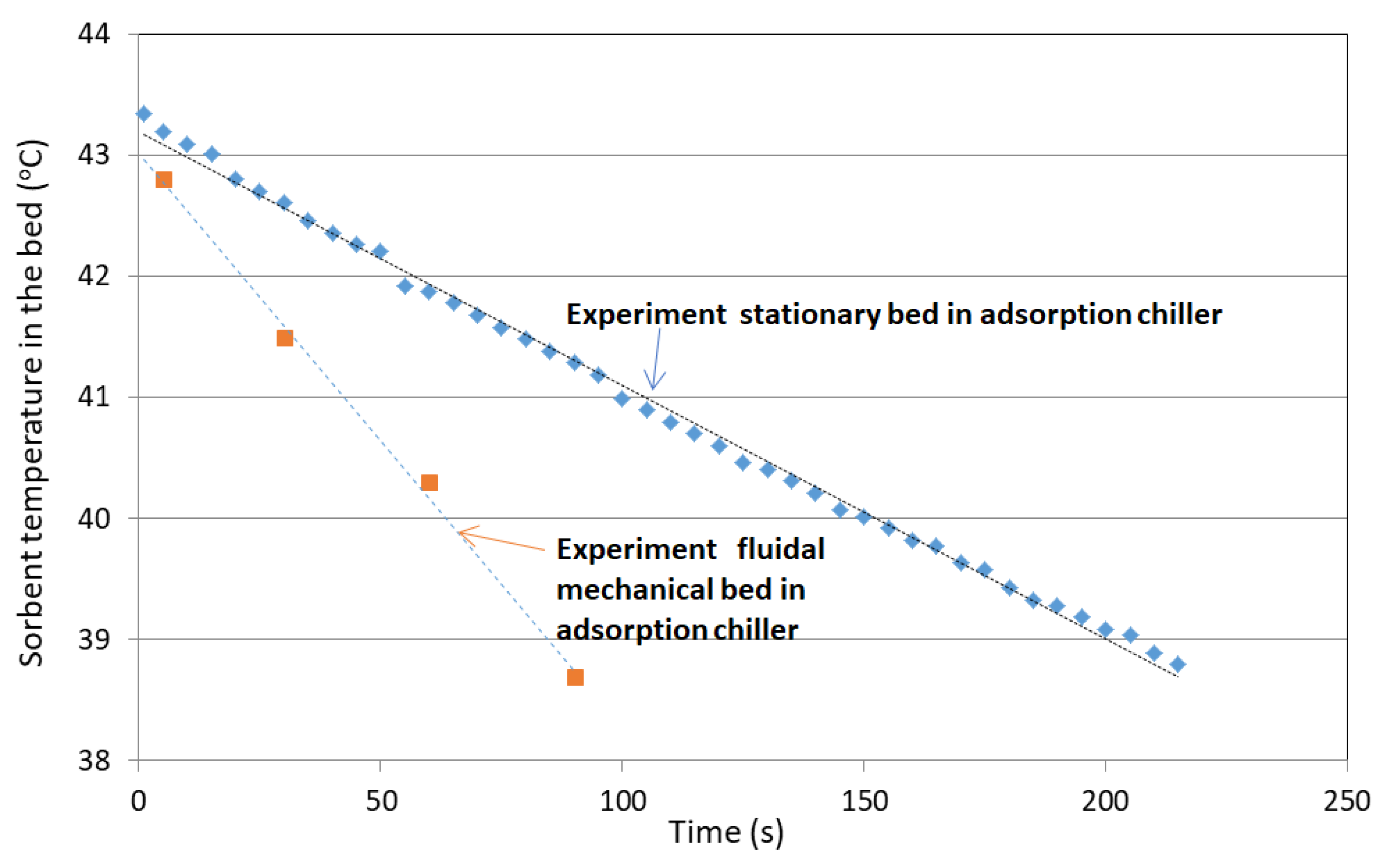
3.1. Adsorption
- Average temperature of silica gel at the inlet: Tav in = 43 °C;
- Average temperature of silica gel at the outlet: Tav out = 39.2 °C;
- Temperature differences between outlet and inlet: ∆T = −3.8 °C;
- Exchanger inclination angle is 43°.
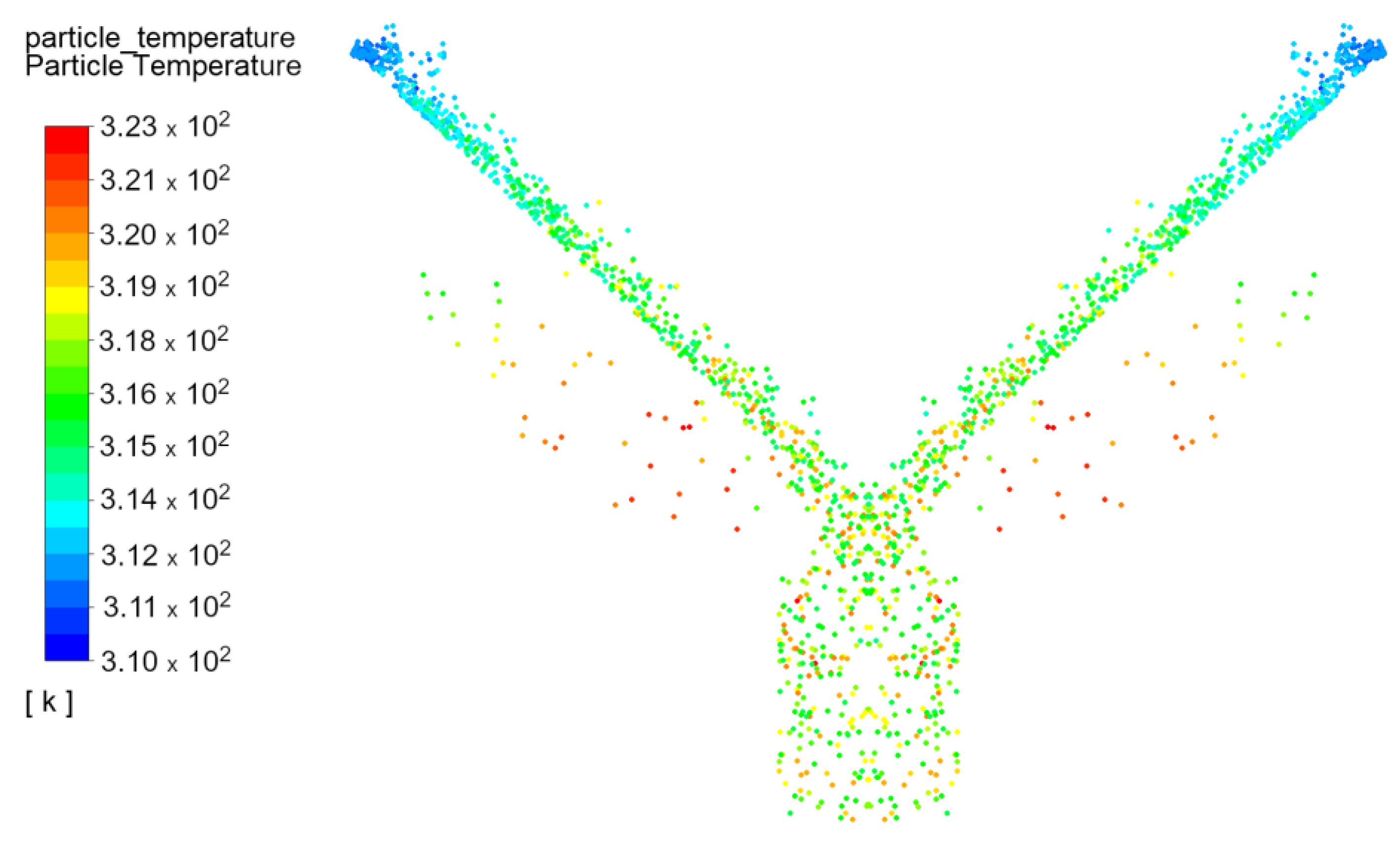
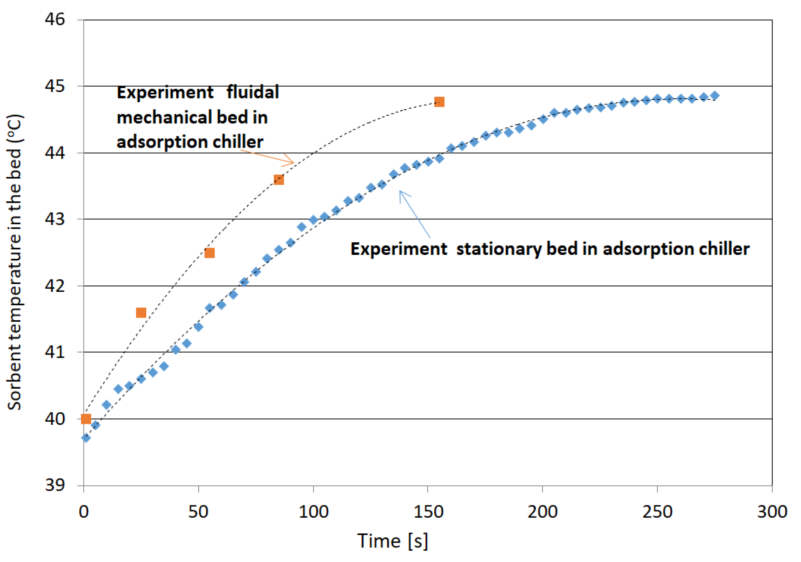
3.2. Desorption
- Average temperature of silica gel at the inlet: Tav in = 39.9 °C;
- Average temperature of silica gel at the outlet: Tav out = 44.7 °C;
- Increase the temperature of silica gel: ∆T = 4.78 °C;
- Exchanger inclination angle is 43°.
4. Discussion
Compare Stationary Bed during Adsorption Desorption Process with a Fluidal Mechanical Bed
- An increase in adsorbed water by approx. 20% compared with fixed beds;
- The amount of desorbed water is approx. 16% greater than in the case of fixed beds.
5. Conclusions
- -
- The application of chillers with fluidised beds will open up the possibility to use the devices in all places where water with a temperature below 55–75 °C is available.
- -
- The use of fluidised systems will reduce the weight (approx. 45%) and dimensions of the device (approx. 67%), which will result in a reduction in capital expenditure (approx. 30–40%) and the possibility of installing it in places where it was previously impossible to install the equipment due to its dimensions and weight.
- -
- Fluidisation of the bed material in the chiller increases heat and mass transfer within the bed.
- -
- The intensive motion of the sorbent particles in the fluidised bed within the heat exchanger has a significant effect on increasing the efficiency of the device.
- -
- On the basis of model-based testing for the system fluidised bed, it can be stated that the heat transfer coefficients for this bed reach values above 0.4 W/(m2K).
- -
- The advantage of sorption devices is the option of cascade configuration thanks to which the heating medium, after giving up the necessary heat in another sorption device, and after cooling, has the right temperature to supply another sorption device.
- -
- The fluidised bed adsorption chiller is a functional device which enables the production of chilled water for technological and air-conditioning purposes as well as the desalination of saline water (seawater, brine, and post-process water), the operating principle of which is based on sorption processes.
- -
- The chiller, due to its increased performance, enables a higher production of condensate in the process of desalination of saltwater compared with a fixed-bed chiller using the same sorbent mass.
Author Contributions
Funding
Data Availability Statement
Conflicts of Interest
References
- IEA (International Energy Agency). Key World Energy Statistics 2020; International Energy Agency: Paris, France, 2020; Volume 33, p. 4649. [Google Scholar]
- Stefański, S.; Nowak, W.; Sztekler, K.; Kalawa, W.; Siwek, T. Applicability of Adsorption Cooling/Desalination Systems Driven by Low-Temperature Waste Heat. IOP Conf. Ser. Earth Environ. Sci. 2019, 214, 012126. [Google Scholar] [CrossRef]
- Sztekler, K.; Kalawa, W.; Nowak, W.; Mika, L.; Gradziel, S.; Krzywanski, J.; Radomska, E. Experimental Study of Three-Bed Adsorption Chiller with Desalination Function. Energies 2020, 13, 5827. [Google Scholar] [CrossRef]
- Choudhury, B.; Saha, B.B.; Chatterjee, P.K.; Sarkar, J.P. An Overview of Developments in Adsorption Refrigeration Systems towards a Sustainable Way of Cooling. Appl. Energy 2013, 104, 554–567. [Google Scholar] [CrossRef]
- Fernandes, M.S.; Brites, G.J.V.N.; Costa, J.J.; Gaspar, A.R.; Costa, V.A.F. Review and Future Trends of Solar Adsorption Refrigeration Systems. Renew. Sustain. Energy Rev. 2014, 39, 102–123. [Google Scholar] [CrossRef]
- Grabowska, K.; Krzywanski, J.; Nowak, W.; Wesolowska, M. Construction of an Innovative Adsorbent Bed Configuration in the Adsorption Chiller-Selection Criteria for Effective Sorbent-Glue Pair. Energy 2018, 151, 317–323. [Google Scholar] [CrossRef]
- Younes, M.M.; El-Sharkawy, I.I.; Kabeel, A.E.; Saha, B.B. A Review on Adsorbent-Adsorbate Pairs for Cooling Applications. Appl. Therm. Eng. 2017, 114, 394–414. [Google Scholar] [CrossRef]
- Thu, K.; Saha, B.B.; Chua, K.J.; Ng, K.C. Performance Investigation of a Waste Heat-Driven 3-Bed 2-Evaporator Adsorption Cycle for Cooling and Desalination. Int. J. Heat Mass Transf. 2016, 101, 1111–1122. [Google Scholar] [CrossRef]
- Sztekler, K.; Kalawa, W.; Mika, Ł.; Mlonka-Medrala, A.; Sowa, M.; Nowak, W. Effect of Additives on the Sorption Kinetics of a Silica Gel Bed in Adsorption Chiller. Energies 2021, 14, 1083. [Google Scholar] [CrossRef]
- Stefański, S.; Mika, Ł.; Sztekler, K.; Kalawa, W.; Lis, Ł.; Nowak, W. Adsorption Bed Configurations for Adsorption Cooling Application. E3S Web Conf. 2019, 108, 01010. [Google Scholar] [CrossRef] [Green Version]
- Sztekler, K.; Kalawa, W.; Mika, Ł.; Sowa, M. Effect of Metal Additives in the Bed on the Performance Parameters of an Adsorption Chiller with Desalination Function. Energies 2021, 14, 7226. [Google Scholar] [CrossRef]
- Chua, H.T.; Ng, K.C.; Malek, A.; Kashiwagi, T.; Akisawa, A.; Saha, B.B. Multi-Bed Regenerative Adsorption Chiller-Improving the Utilization of Waste Heat and Reducing the Chilled Water Outlet Temperature Fluctuation. Int. J. Refrig. 2001, 24, 124–136. [Google Scholar] [CrossRef]
- Krzywanski, J.; Grabowska, K.; Herman, F.; Pyrka, P.; Sosnowski, M.; Prauzner, T.; Nowak, W. Optimization of a Three-Bed Adsorption Chiller by Genetic Algorithms and Neural Networks. Energy Convers. Manag. 2017, 153, 313–322. [Google Scholar] [CrossRef]
- Krzywanski, J.; Grabowska, K.; Sosnowski, M.; Zylka, A.; Kulakowska, A.; Czakiert, T.; Sztekler, K.; Wesolowska, M.; Nowak, W. Heat Transfer in Adsorption Chillers with Fluidized Beds of Silica Gel, Zeolite, and Carbon Nanotubes. Heat Transf. Eng. 2022, 43, 172–182. [Google Scholar] [CrossRef]
- Thu, K.; Ng, K.C.; Saha, B.B.; Chakraborty, A.; Koyama, S. Operational Strategy of Adsorption Desalination Systems. Int. J. Heat Mass Transf. 2009, 52, 1811–1816. [Google Scholar] [CrossRef]
- Wang, D.C.; Li, Y.H.; Li, D.; Xia, Y.Z.; Zhang, J.P. A Review on Adsorption Refrigeration Technology and Adsorption Deterioration in Physical Adsorption Systems. Renew. Sustain. Energy Rev. 2010, 14, 344–353. [Google Scholar] [CrossRef]
- Ng, K.C.; Thu, K.; Kim, Y.; Chakraborty, A.; Amy, G. Adsorption Desalination: An Emerging Low-Cost Thermal Desalination Method. Desalination 2013, 308, 161–179. [Google Scholar] [CrossRef]
- Wang, Q.; Gao, X.; Xu, J.Y.; Maiga, A.S.; Chen, G.M. Experimental Investigation on a Fluidized-Bed Adsorber/Desorber for the Adsorption Refrigeration System. Int. J. Refrig. 2012, 35, 694–700. [Google Scholar] [CrossRef]
- Zhu, L.Q.; Tso, C.Y.; Chan, K.C.; Wu, C.L.; Chao, C.Y.H.; Chen, J.; He, W.; Luo, S.W. Experimental Investigation on Composite Adsorbent—Water Pair for a Solar-Powered Adsorption Cooling System. Appl. Therm. Eng. 2018, 131, 649–659. [Google Scholar] [CrossRef]
- Engelpracht, M.; Gibelhaus, A.; Seiler, J.; Graf, S.; Nasruddin, N.; Bardow, A. Upgrading Waste Heat from 90 to 110 °C: The Potential of Adsorption Heat Transformation. Energy Technol. 2021, 9, 2000643. [Google Scholar] [CrossRef]
- Horibe, A.; Haruki, N.; Hiraishi, D. Sorption-Desorption Operations on Two Connected Fluidized Bed Using Organic Sorbent Powder. Int. J. Heat Mass Transf. 2013, 65, 817–825. [Google Scholar] [CrossRef]
- Eflita, Y.; Ismoyo, H.; Muhamad Adrian, D.; Yusuf, L.H. Static and Dynamic Analysis of Vibro Fluidized Bed Dryer Using Finite Element Method. E3S Web Conf. 2018, 73, 3–6. [Google Scholar] [CrossRef] [Green Version]
- Rogala, Z.; Kolasiński, P.; Gnutek, Z. Effect of Operating Conditions on Performance of Silica Gel-Water Air-Fluidised Desiccant Cooler. E3S Web Conf. 2017, 22, 00146. [Google Scholar] [CrossRef] [Green Version]
- Nikam, S.; Mandal, D. A Study on Fluidization of Activated Carbon Particles in Gas-Solid Fluidized Bed. Indian. Chem. Eng. 2021, 63, 478–490. [Google Scholar] [CrossRef]
- Chen, C.H.; Ma, S.S.; Wu, P.H.; Chiang, Y.C.; Chen, S.L. Adsorption and Desorption of Silica Gel Circulating Fluidized Beds for Air Conditioning Systems. Appl. Energy 2015, 155, 708–718. [Google Scholar] [CrossRef]
- Hamed, A.M.; Abd El Rahman, W.R.; El-Eman, S.H. Experimental Study of the Transient Adsorption/Desorption Characteristics of Silica Gel Particles in Fluidized Bed. Energy 2010, 35, 2468–2483. [Google Scholar] [CrossRef]
- Chen, C.H.; Schmid, G.; Chan, C.T.; Chiang, Y.C.; Chen, S.L. Application of Silica Gel Fluidised Bed for Air-Conditioning Systems. Appl. Therm. Eng. 2015, 89, 229–238. [Google Scholar] [CrossRef]
- Hamed, A.M. Experimental Investigation on the Adsorption/Desorption Processes Using Solid Desiccant in an Inclined-Fluidized Bed. Renew. Energy 2005, 30, 1913–1921. [Google Scholar] [CrossRef]
- Llop, M.F.; Madrid, F.; Arnaldos, J.; Casal, J. Fluidization at Vacuum Conditions. A Generalized Equation for the Prediction of Minimum Fluidization Velocity. Chem. Eng. Sci. 1996, 51, 5149–5157. [Google Scholar] [CrossRef]
- Crowe, C.T.; Schwarzkopf, J.D.; Sommerfeld, M.; Tsuj, Y. Multi-Phase Flows with Droplets and Particles; CRC Press: Boca Raton, FL, USA, 1998; ISBN 9781439840511. [Google Scholar]
- ANSYS, Inc. Ansys Fluent Theory Guide; ANSYS, Inc.: Canonsburg, PA, USA, 2021. [Google Scholar]
- Adamczyk, W.P.; Klimanek, A.; Białecki, R.A.; Wȩcel, G.; Kozołub, P.; Czakiert, T. Comparison of the Standard Euler–Euler and Hybrid Euler–Lagrange Approaches for Modeling Particle Transport in a Pilot-Scale Circulating Fluidized Bed. Particuology 2014, 15, 129–137. [Google Scholar] [CrossRef]
- Magnussen, B.F.; Hjertager, B.H. On Mathematical Modeling of Turbulent Combustion with Special Emphasis on Soot Formation and Combustion. In Symposium (International) on Combustion; Elsevier: Amsterdam, The Netherlands, 1977; Volume 16, pp. 719–729. [Google Scholar] [CrossRef]
- Menter, F.R. Two-Equation Eddy-Viscosity Turbulence Models for Engineering Applications. AIAA J. 1994, 32, 1598–1605. [Google Scholar] [CrossRef] [Green Version]
- Sztekler, K.; Kalawa, W.; Nowak, W.; Mika, L.; Krzywanski, J.; Grabowska, K.; Sosnowski, M.; Alharbi, A. Performance Evaluation of a Single-Stage Two-Bed Adsorption Chiller With Desalination Function. J. Energy Resour. Technol. 2021, 143, 082101. [Google Scholar] [CrossRef]
- Sztekler, K.; Siwek, T.; Kalawa, W.; Lis, L.; Mika, L.; Radomska, E.; Nowak, W. CFD Analysis of Elements of an Adsorption Chiller with Desalination Function. Energies 2021, 14, 215. [Google Scholar] [CrossRef]


| No. | Working Pair | Hot Water Temperature °C | Cold Water Temperature °C | SCP W/kg | SDWP m3/Tonne | COP | Details |
|---|---|---|---|---|---|---|---|
| 1 | Silica gel–water | 85.0 | 24.0 | 30.2 | 0.96 | 0.28 | two-stage, four-bed |
| 2 | 70.0 | 16.0 | 12.3 | - | 0.23 | ||
| 3 | 70.0 | 27.6 | - | 9.97 | - | four-bed, int. heat recovery | |
| 4 | 85.0 | 30.0 | 112.0 | 4.0 | 0.46 | two-bed, solar heat-driven | |
| 5 | 85.0 | 25.0 | ~140.0 | 5.3 | ~0.50 | ||
| 6 | 85.0 | 15.0 | ~225 | 8.0 | ~0.55 | ||
| 7 | 60.0 | 25.0 | - | - | 0.64 | three-bed | |
| 8 | 85.5 | 29.5 | 125.0 | - | 0.51 | two-bed with optimized modular | |
| 9 | 85.4 | 30.3 | 86.4 | - | 0.34 |
| Parameter | Value |
|---|---|
| Granulation, μm | 400–800 |
| Specific surface area, m2/g | 750–830 |
| Bulk density, kg/m3 | 755 |
| Actual density, kg/m3 | 2200 |
| Regeneration temperature, °C | ˂90 |
| Average pore diameter, nm | 2–3 |
| Specific thermal capacity, J/kgK | 924 |
| Thermal conductivity, W/mK | 0.175 |
| Desorption | ||||||||
| Exp. 30 s | Model 30 s | Exp. 60 s | Model 60 s | Exp. 90 s | Model 90 s | Exp. 160 s | Model 160 s | |
| Temperature of silica gel at the inlet [°C] | 41.0 | 40.3 | 42.2 | 41.6 | 43.2 | 42.8 | 44.6 | 44.4 |
| Temperature of silica gel at the inlet [°C] | 41.4 | 40.7 | 42.5 | 42.0 | 43.6 | 43.2 | 44.8 | 44.6 |
| Adsorption | ||||||||
| Exp. 30 s | Model 30 s | Exp. 60 s | Model 60 s | Exp. 90 s | Model 90 s | |||
| Temperature of silica gel at the inlet [°C] | 42.0 | 43.1 | 40.8 | 41.3 | 39.1 | 38.8 | ||
| Temperature of silica gel at the inlet [°C] | 41.5 | 41.9 | 40.3 | 40.6 | 38.7 | 38.3 | ||
Disclaimer/Publisher’s Note: The statements, opinions and data contained in all publications are solely those of the individual author(s) and contributor(s) and not of MDPI and/or the editor(s). MDPI and/or the editor(s) disclaim responsibility for any injury to people or property resulting from any ideas, methods, instructions or products referred to in the content. |
© 2023 by the authors. Licensee MDPI, Basel, Switzerland. This article is an open access article distributed under the terms and conditions of the Creative Commons Attribution (CC BY) license (https://creativecommons.org/licenses/by/4.0/).
Share and Cite
Kalawa, W.; Sztekler, K.; Mlonka-Mędrala, A.; Radomska, E.; Nowak, W.; Mika, Ł.; Bujok, T.; Boruta, P. Simulation Analysis of Mechanical Fluidized Bed in Adsorption Chillers. Energies 2023, 16, 5817. https://doi.org/10.3390/en16155817
Kalawa W, Sztekler K, Mlonka-Mędrala A, Radomska E, Nowak W, Mika Ł, Bujok T, Boruta P. Simulation Analysis of Mechanical Fluidized Bed in Adsorption Chillers. Energies. 2023; 16(15):5817. https://doi.org/10.3390/en16155817
Chicago/Turabian StyleKalawa, Wojciech, Karol Sztekler, Agata Mlonka-Mędrala, Ewelina Radomska, Wojciech Nowak, Łukasz Mika, Tomasz Bujok, and Piotr Boruta. 2023. "Simulation Analysis of Mechanical Fluidized Bed in Adsorption Chillers" Energies 16, no. 15: 5817. https://doi.org/10.3390/en16155817