Article

A Comprehensive Analysis on the Influence of the Adopted Cumulative Peak Current Distribution in the Assessment of Overhead Lines Lightning Performance

1
Graduate Program in Electrical Engineering, Universidade Federal de Minas Gerais, Av. Antônio Carlos 6627, Belo Horizonte 31270-901, MG, Brazil
2
Department of Electrical Engineering, CEFET-MG—Federal Center of Technological Education of Minas Gerais, Av. Amazonas, 7675, Nova Gameleira, Belo Horizonte 30510-000, MG, Brazil
3
Electromagnetic Compatibility Laboratory, Swiss Federal Institute of Technology Lausanne (EPFL), 1015 Lausanne, Switzerland
4
Associate METSCO/EDM/Kinectrics, Toronto, ON, Canada
*
Author to whom correspondence should be addressed.
Energies 2023, 16(15), 5836; https://doi.org/10.3390/en16155836
Submission received: 19 June 2023 / Revised: 26 July 2023 / Accepted: 2 August 2023 / Published: 7 August 2023

Abstract

:
Backflashover rate (BFR) is strongly dependent on the cumulative peak current distribution (CCD) adopted in the calculations. An original aspect of the present work is that such dependence is simultaneously assessed in estimating the probability of the critical current being exceeded as well as in the annual number of flashes to the line. An IEEE brochure recommends that the distribution values that characterize the atmospheric characteristic of the region under study as accurately as possible be used. The objective of this article is to evaluate the impact of the use of different CCDs, related to several measurements carried out around the world, in the estimation of the lightning performance of transmission lines (TLs). Structures of 138, 230 and 500 kV were analyzed. In the simulations, representative curves of lightning associated with measurements taken at Monte San Salvatore (MSS), Morro do Cachimbo (MCS) and TLs in Japan (TLJ) were considered. The distributions recommended by the IEEE and by the CIGRE and the distributions of Berger obtained from MSS, MCS and TLJ were considered. The presented results indicate differences of up to 100% between the considered work distributions and the IEEE one for certain values of tower footing impedance.

1. Introduction

Despite the evolution of the approaches to estimate transmission line (TL) performance and the advancement of the power industry related to the production and development of protective equipment, lightning is still an issue and remains one of the main causes of TL outages [1]. Given the increase in electricity consumption, coupled with the integration of new energy sources into the grid, it has become increasingly crucial to ensure the operational quality and efficient energy transport within the network [2]. Lightning outages of TLs are mostly related to downward lightning flashes, which usually contain one or more return stroke currents [3]. Statistically, the peak value of first strokes is typically two to three times higher than that of the subsequent strokes, which makes the first stroke currents the primary cause of unscheduled outages [1]. The topic of lightning performance for transmission lines is addressed in international standards by organizations such as IEEE and CIGRE, with documents including [1,3,4]. In addition, the emerging IEC-60099 series from the International Electrotechnical Committee provides an in-depth look into the deployment of surge arresters in electrical systems, including but not limited to high-voltage transmission lines [5]. The application of surge arresters takes on heightened importance when transmission lines are situated in areas with pronounced lightning activity or when such lines exhibit high values of tower foot resistance.
The estimation of the annual number of backflashovers per 100 km of a transmission line, denoted as B F R , can be determined using the following expression [4]:
      B F R = 0.6 · N T L · P I P > I c r i t    
In (1), P ( I P > I c r i t ) represents the probability of the peak current of the first stroke exceeding the minimum current required for insulation flashover. The factor 0.6 is employed to account for the negligible impact of strokes along the span. The annual number of flashes per 100 km of the line, denoted as N T L , is calculated using the following expression:
    N T L = N g · l T L · W  
where N g is the ground flash density (GFD in flashes per km2 per year), W is the so-called attractive distance of the line and l T L = 100 km.
From (1), it is clear that the estimated B F R is strongly dependent on the cumulative current distribution (CCD) adopted in the calculations. In most works dealing with TLs’ lighting performance, the distributions proposed by the CIGRE and IEEE standards are adopted [6,7,8,9,10,11,12,13,14,15,16]. Such distributions, often called “global distributions”, were obtained by combining direct (Berger’s data from the instrumented tower of Mount San Salvatore [17]) and indirect (magnetic links) current measurements obtained from different countries around the world [3,18,19,20]. At the time these distributions were proposed, the aim of combining direct and indirect measurements was to enhance the sample size and consequently minimize statistical uncertainties. However, the use of such distributions for lightning protection studies was questioned in [4], on the grounds that it might not be a good approach to “compromise” direct current measurements obtained from instrumented towers by adding less accurate indirect measurements based on magnetic links. In the same direction, the recently updated CIGRE brochure on procedures for estimating TL lightning performance suggests that measurements from instrumented towers should be used whenever they are available, in view of greater accuracy in relation to global distributions and due to a better characterization of lightning activity in different regions of the globe [1].
The context described raised the following question: what are the differences in the estimated TL backflashover rate assuming the use of “pure distributions”, which considers only direct measurements obtained from instrumented towers, in relation to the use of the so-called global distributions? In [21], a first attempt to clarify this aspect was made by the authors, comparing the B F R obtained by adopting the standard IEEE distribution (median value of 31 kA) and the pure distribution obtained at Morro do Cachimbo Station (MCS, median value of 43.3 kA). Despite the latter distribution having a median value about 40% higher than the former, it has been shown that, depending on the tower footing resistance value, the use of the MCS distribution could lead to a lower BFR. As shown in [21], this stems from the fact that the probability that the peak value of first stroke currents exceeds 90 kA is smaller considering the MCS distribution compared to the IEEE one. A similar conclusion was drawn in a recent contribution [22] where some complementary analyses were carried out considering also the standard CIGRE distribution and the pure Mount San Salvatore distribution. The reported results underscore the significance and necessity of conducting a more comprehensive analysis of the impact of the chosen cumulative current distribution on the calculation of the transmission line outage rate.
Although frequently overlooked in calculations, the cumulative current distribution also influences the determination of the line’s attractive distance. In accordance with IEEE and CIGRE standards, the attractive distance is commonly computed using Eriksson’s concept of average attractive distance, which assumes a representative median value of 35 kA for the peak current of the first stroke to estimate the line’s attractiveness to lightning. [4,23,24]. Interaction of these parameters also led to several evaluations of the compensation of peak current distributions on structures to a fictitious “level ground” distribution, for example, with a median first negative return stroke peak current of 13 kA suggested by Sargent [25], 25 kA by Mousa [26] and a range of 15–21 kA, for six different attractive radius expressions, by Borghetti et al. [27]. However, taking into account the different cumulative current distributions available, and more importantly, considering that they vary in different regions of the globe, it is expected that the attractive distance and, ultimately, the number of flashes per year to the line will depend on the adopted CCD for a well-grounded structure.
The main objective of this paper is to present a comprehensive analysis of the influence of the adopted CCD, considering both global and pure distributions, on the calculation of the TL backflashover outage rate. An original aspect of the present work is that such influence is simultaneously assessed in estimating the probability of the critical current being exceeded as well as in the amount of lightning on the TL. In addition, the paper improves previous analysis by considering also the CCD obtained from measurements performed on instrumented towers in Japan and extending the evaluations to 138, 230 and 500 kV lines. It is expected that the results will support decision making on which CCD to adopt in TL performance studies depending on their voltage level, geographic location and desired accuracy.
This article presents seven sections organized as follows. In Section 2, the instrumented tower and standard cumulative peak current distributions considered are discussed. The TLs considered as study cases are presented in Section 3. Section 4 describes the approaches adopted to compute the annual number of flashes to the TLs. Section 5 presents the models adopted for the first return stroke currents and line components to compute the TL backflashover rate. The results are presented and discussed in Section 6 and the main conclusions are summarized in Section 7.

2. Cumulative Statistical Distribution of Peak Currents

The severity of lightning flashes in terms of flashovers of the line insulation is closely related to the lightning current parameters, namely: current peak value, maximum rate of rise (i.e., steepness), average rate of rise, wave front duration, overall duration, charge transfer and specific energy (action integral). Of these parameters, the most important for studies of lightning protection of electrical systems is the peak current value. In fact, the search for a peak current distribution for lightning protection dates back to the 1930s, with consensus reached in 1950 [28]. A comprehensive survey of different peak current distributions, along with background information, can be found in [3]. Below, a summary of the most commonly used distributions in the lightning protection scenario of transmission lines is presented and briefly discussed.
The “standard” peak current distributions for negative first return strokes, as observed in national and international lightning protection standards, heavily rely on direct lightning current measurements carried out in Switzerland between 1963 and 1971 by K. Berger et al. [17]. Berger’s distribution of first strokes is based on 101 direct measurements accompanied by optical observations to discriminate downward from upward flashes. Considering these data (101 direct downward flash measurements) and that the peak current is log-normally distributed, Equation (3), a median value of μ I = 30 kA and a logarithmic standard deviation of σ l n I = 0.61 were determined [11].
  p I P I P = 1 I P σ l n I P 2 π exp 1 2 l n I P l n μ I P σ l n I P 2                  
Despite the reliability of Berger’s current measurements, the associated current distribution suffers from a lack of a greater number of samples at the ends of the distribution, particularly of the high values, which can bring uncertainty in some engineering applications. In this regard, in an attempt to reduce the statistical uncertainties, Berger’s data have often been combined with indirect measurements of lightning currents obtained (in different countries) using magnetic links [18,19,20]. These combined distributions gave rise to the so-called “standard” or “global” peak current distributions, of which the best known are those proposed by IEEE and CIGRE. The IEEE distribution was first proposed in [18] and assumed that the probability to exceed a given peak current value I p can be calculated using the following log-logistic equation:
  P I p = 1 1 + I P 31 2.6
The CIGRE distribution, proposed in [19], assumes a log-normal distribution for the current peak approximated by two straight lines, one of them modeling currents smaller than 20 kA (log-normal parameters: μ I p = 61 kA and σ l n I p = 1.33 ) and the other for currents larger than 20 kA (log-normal parameters: μ I p = 33.3 kA and σ l n I p = 0.605 ). Over the past few decades, IEEE and CIGRE distributions have been the most widely used to estimate the transmission line outages due to lightning (e.g., [14,29,30,31,32,33,34]).
As mentioned before, the recently updated CIGRE brochure on transmission lines’ lightning performance recommends that CCDs be derived preferably from direct measurements on grounded structures that closely resemble transmission line towers [1]. Based on this suggestion, in addition to Berger’s distribution, two others would be applicable to lightning performance studies, namely: (a) the distribution by Takami and Okabe determined from measurements performed on instrumented towers of transmission lines in Japan with tower heights from 60 to 140 m [35] and (b) the Morro do Cachimbo Station distribution determined from direct measurements of lightning currents on a 60 m high instrumented tower at the Morro do Cachimbo Station, in Brazil [36]. Log-normal parameters associated with these two distributions are presented in Table 1, which also summarizes the discussed peak current distributions.
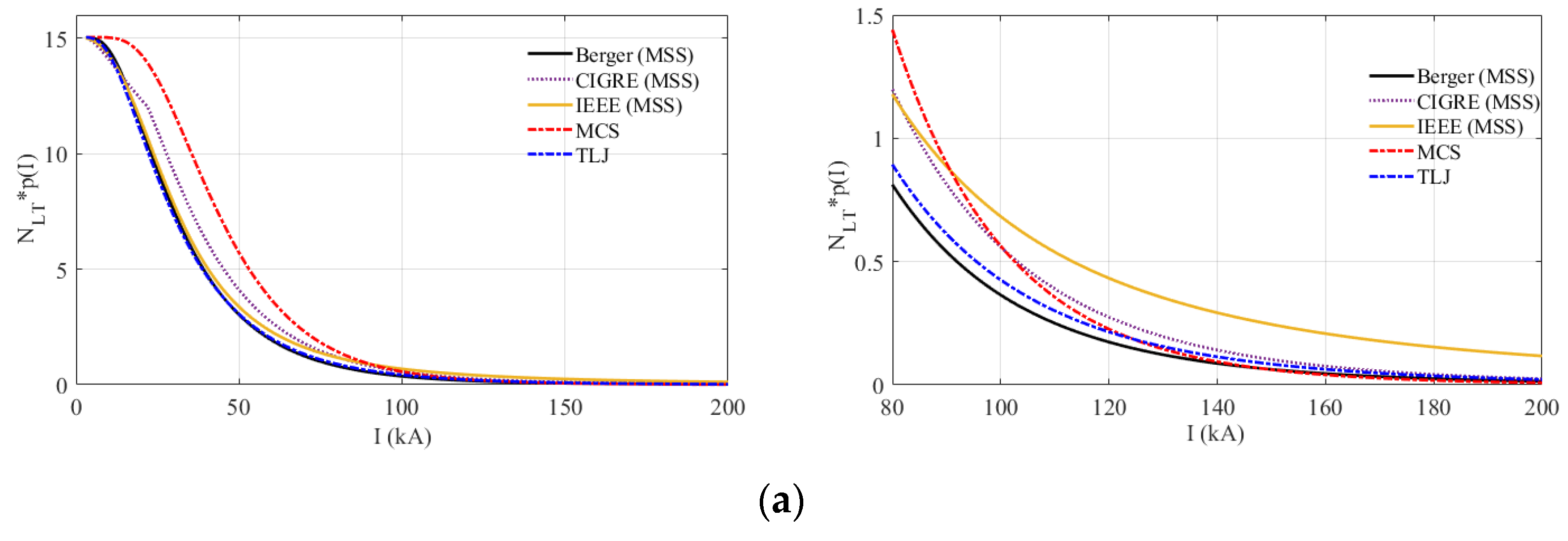
Figure 1 illustrates the CCDs of first strokes summarized in Table 1. In Figure 1a, the behavior of these distributions is shown in the range of 0 to 200 kA, while in Figure 1b a close look between 80 kA to 200 kA is shown, which is a range of great importance for TL backflashover evaluation.
Up to approximately 80 kA, the MSS, IEEE, CIGRE and TLJ distributions demonstrate reasonably comparable cumulative probability values for a given current and, in turn, much lower values than those predicted by the MCS distribution. According to Figure 1b, this behavior progressively inverts from about 90 kA, when the curve associated with the MCS distribution crosses the IEEE curve. This trend continues and the curve associated with the cumulative distribution of MCS crosses the curves associated with CIGRE, TLJ and Berger distributions at 108 kA, 125 kA and 148 kA, respectively.

3. Simulated Transmission Lines

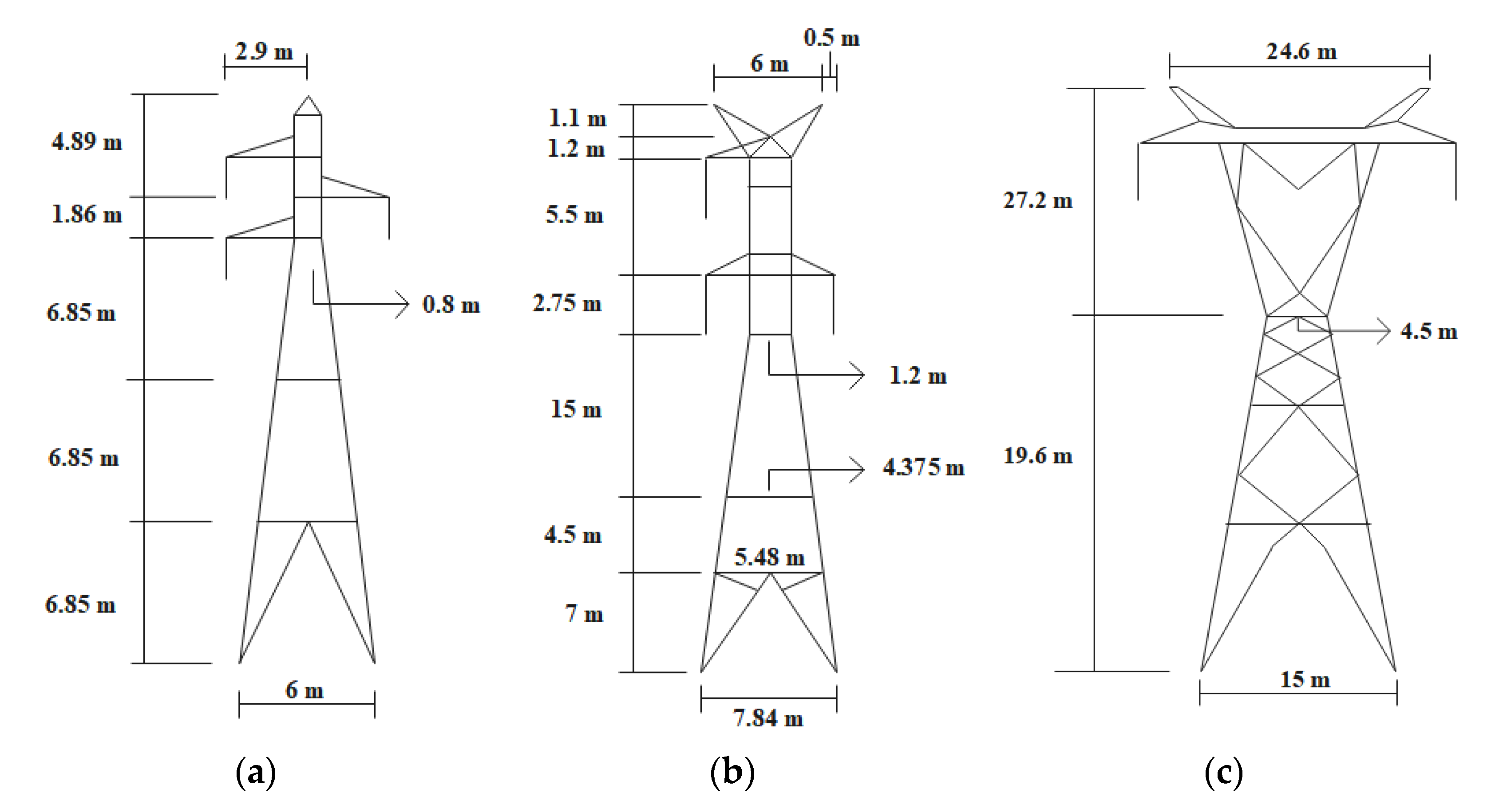
In order to present a comprehensive evaluation of the influence of the adopted CCD on the TL performance estimation, three different overhead transmission lines are considered, namely typical 138 kV, 230 kV and 500 kV Brazilian lines. The geometry of the towers of each transmission line is depicted in Figure 2. The characteristics of the conductors for each transmission line are indicated in Table 2. Span lengths of 400 m, 450 m and 550 m are assumed respectively for the 138 kV, 230 kV and 500 kV lines. The sags of the phase conductors and shield wires of each TL are indicated in the caption of Figure 2 and consider typical tensions in the cables and guidelines for minimum midspan clearances. All the transmission line parameters correspond to real transmission lines in Brazil. Specifically, the sag of the phase cables takes into account the minimum ground clearance heights required by safety standards. The span lengths also correspond to typical lengths of real lines, considering their respective voltage levels. Finally, lightning impulse critical flashover overvoltages (CFOs) of 650 kV, 1095 kV and 1800 kV are assumed for the 138 kV, 230 kV and 500 kV lines, respectively.
It is important to mention that in the evaluations presented in this work, the performance calculations of the lines consider their average parameters. However, these parameters may vary substantially in some sections along the line route, for example, due to the terrain. Additionally, environmental and meteorological conditions can also influence the insulation capacity of the transmission line. In the evaluation of line performance, if there are sections that exhibit critical behavior in terms of lightning performance, specific evaluations should be conducted. These evaluations can be performed using the same approach as in this work but considering the specific parameters of the transmission line in the respective section.
In Section 4, the incidence models used to determine the annual number of flashes to lines, which correspond to an intermediate step in the calculation of the B F R , are discussed. Then, the modeling of the TL components to estimate the lightning overvoltages through the insulators, including the representation of the first stroke return current, is presented in Section 5, All simulations were conducted using the Alternative Transients Program (ATP) [37,38].

4. Incidence Models

A crucial aspect in evaluating the lightning performance of TLs is to ascertain the frequency of lightning strikes on the line per 100 km annually, i.e., the parameter N T L in (1). Two main factors influence this number: (i) the lightning ground flash density, which is an intrinsic characteristic of the region crossed by the transmission line; and (ii) the attractive distance of the line, which depends mostly on the TL geometry and on the lightning stroke characteristics. The estimation of lightning incidence on overhead transmission lines is carried out using the commonly known lightning attachment models. An extensive review of the lightning stroke attachment to transmission lines and methods for evaluating it can be found in [39]. In general, two approaches are considered to evaluate the attractive distance of TLs: (i) the electro-geometric method (EGM) and (ii) the leader progression method (LPM).
The EGM is built upon the notion of striking distance ( r s ), which represents the distance between the downward leader tip and the grounded structure precisely when the upward connecting leader is initiated [40,41,42,43,44,45]. Generally, the striking distance is calculated using an equation of the form r s = A · I p B , where I p represents the peak current of the lightning and A and B are constants determined through empirical calibration. For a comprehensive summary of the various proposed values for A and B , refer to [19]. This model form does not consider an explicit dependence on the striking distance with the structure height, i.e., it does not account for the fact the taller structures are expected to attract more lightning than shorter ones. This is typically perceived as a limitation of the classical EGM. However, the EGMs do indicate a robust correlation between impulse charge and peak current, which is substantiated by observations [3,17].
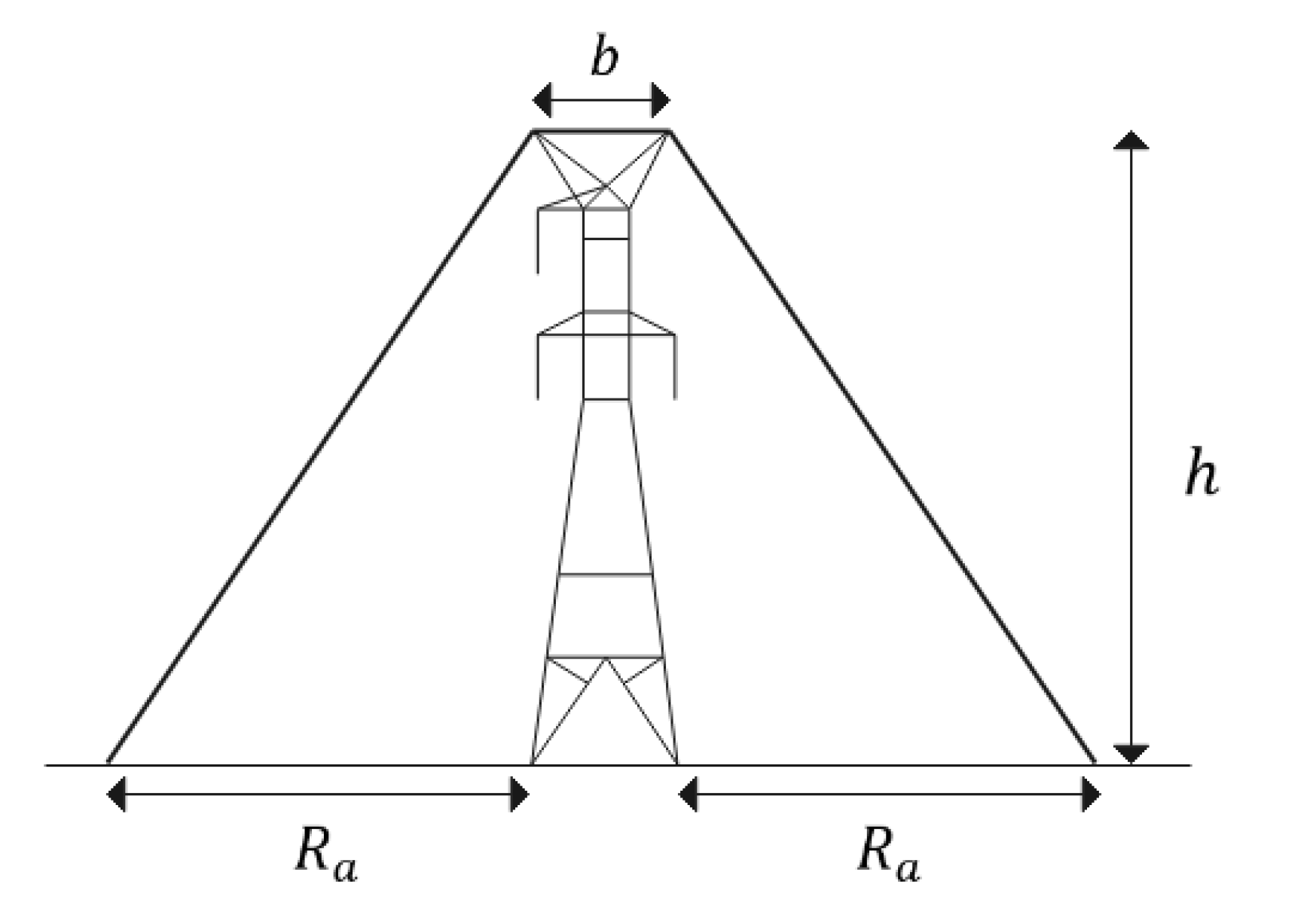
In order to address certain limitations of the EGM, the leader progression method was developed to enhance the simulation of the lightning attachment process to grounded structures [23,46,47,48,49]. This method is based on a deeper understanding of the underlying physics, aiming to provide more accurate and consistent results, and involves a step-by-step simulation of the approaching downward stepped leader until the start of the upward leader. One important output of the extensive application of the LPM to the problem of lighting incidence on grounded structures is the concept of attraction distance or attractive radius. The attractive radius is defined as a limited lateral distance between the potential downward leader and the structure. Attachment between the transmission line and a lightning channel will occur when a downward leader approaches within this attractive radius. Figure 3 illustrates this concept using a transmission line tower as an example.
The attractive radius R a is generally described by the following equation form:
R a h , I p = ξ h E I p F      
where h is the structure height and ξ , E and F are constants that are dependent on the assumptions adopted in the LPM application. In this paper, the constants proposed by Eriksson [50] and recommended by brochures and standards [1,3,4,24] are considered, which leads to
R a h , I p = 0.67 · h 0.6 I p 0.74  
Utilizing Equation (6), the yearly number of lightning flashes striking the transmission line per 100 km can be calculated as follows:
N T L = 0.1 N g [ b + I p = 0 I p = R a h , I p p I p d I p ]  
In Equation (7), b represents the distance between the shielding wires. Here, the equivalent attractiveness of the transmission line is computed by integrating R a h , I p weighted by the probability density function p I p . Thus, for the same tower geometry, the expected number of lightning strikes to the line will depend on the adopted CCD.
Finally, Expression (8) is still widely used in standards and brochures to estimate the line attractiveness to lightning.
  R a v h = 14 · h 0.6
This simplified expression, known as the average attractive radius, was introduced by Eriksson. It assumes a median peak current value of I p = 35 kA in Equation (6) and is based on a substantial amount of experimental data from lightning flashes observed on various structures in South Africa [49]. The average value of 35 kA was assumed based on measurements available at that time, mainly considering the extensive works by Berger [17] and Popolansky [19]. However, it is important to emphasize that (8) represents the average attractive radius of structures as a function of their height, considering solely an average value of current. Considering (8), the following widely adopted expression for N T L in TL performance studies is obtained:
  N T L = 0.1 N g b + 28 h 0.6

5. Modeling Guidelines

5.1. Current Waveforms

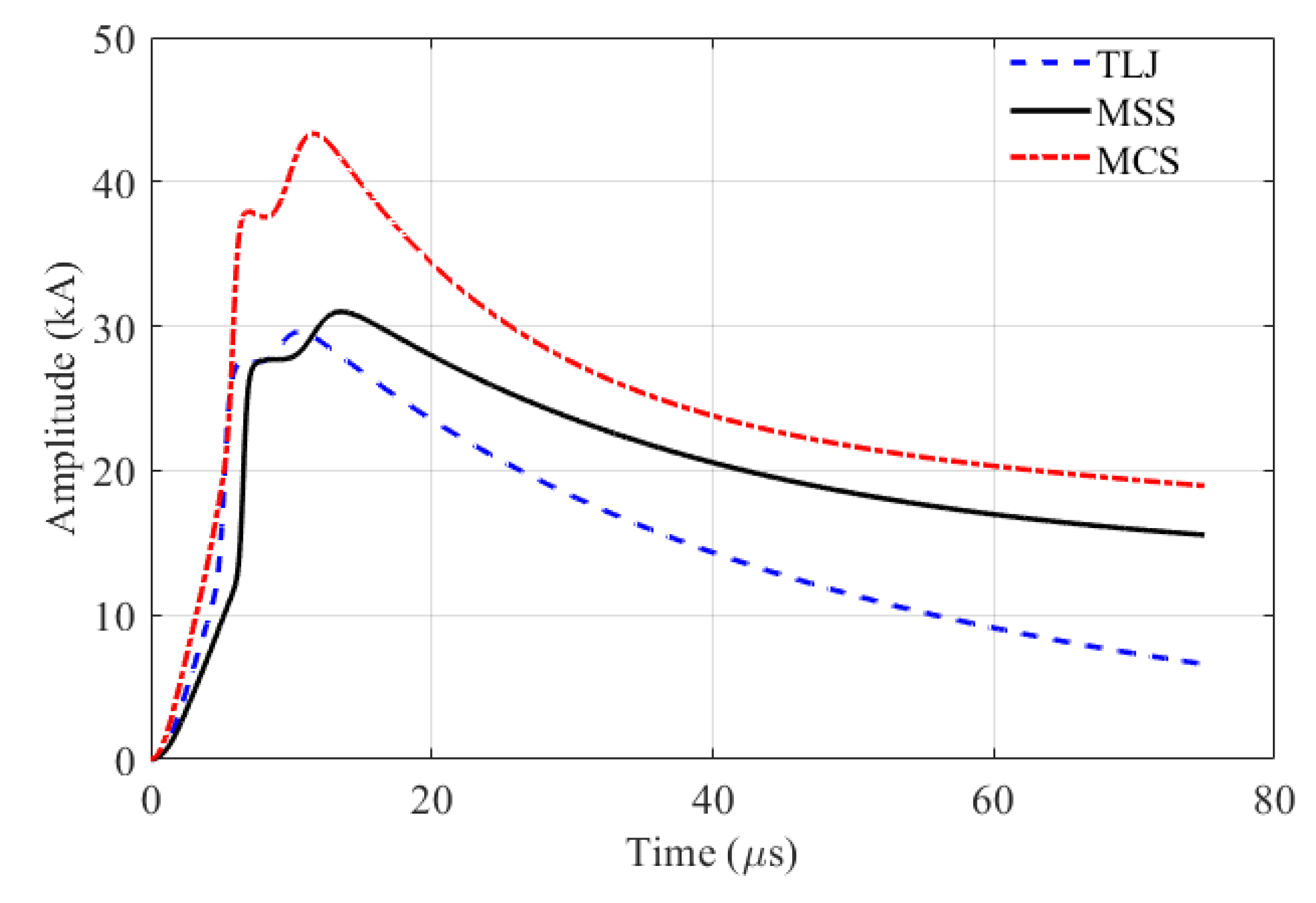
The current waveforms depicted in Figure 4 have been adopted in the simulations. These waveforms closely replicate the primary median parameters of negative downward lightning first stroke currents measured at Mount San Salvatore (MSS) [17], Morro do Cachimbo Station (MCS) [36] and instrumented transmission line towers in Japan (TLJ) [35]. The curves are modeled as the sum of Heidler’s function, as detailed in [24,51,52].
The curve of MSS, representing first stroke currents, is characterized by a peak value of 31.1 kA and a virtual front time of 3.8 µs. Likewise, the curve of MCS, also representing first stroke currents, is characterized by a peak value of 43.3 kA and a virtual front time of 4.2 µs. This waveform was generated to update the data presented in [14]. The curve associated with measurements conducted in Japan, as presented by Takami and Okabe in [29], is also representative of the first stroke current, with a peak value of 29.3 kA and a virtual front time of 3.2 µs.
The quality of the synthesized curves can be assessed in Table 3, where the main parameters extracted from the current waveforms shown in Figure 4 are compared with the median values (indicated between parentheses) obtained from the log-normal distribution of negative first stroke currents measured at Mount San Salvatore [17], Morro do Cachimbo station [36] and TL towers in Japan [35]. The percentage values correspond to the errors obtained.
As seen in Figure 4, the representative waveforms of measurements carried out at MSS and those carried out by Takami and Okabe in Japan have similar peak values, 31.1 and 29.3 kA, with a percentage difference of approximately 6%. The curve associated with MCS has a peak current value approximately 30% higher compared to the other waveforms. It is important to underscore that the highest peak value of the MCS current was recently confirmed in [36], taking into account the updated statistics of parameters related to negative first return stroke currents. The corresponding database, which is derived from 51 negative cloud-to-ground flashes, stands as the only one garnered from tropical regions that holds statistical significance.
Finally, it is worth mentioning that in this paper only first stroke currents are considered. Although the subsequent strokes are typically faster (shorter current wave rise time), in terms of insulation withstand capability, the amplitude prevails. Some subsequent return strokes deviate from the previously formed channel and exhibit pronounced stepping in the bottom portion of the channel. As detailed in [53], subsequent strokes that create a new termination on the ground have characteristics that lie between the first strokes initiated by stepped leaders and subsequent strokes following a previously formed channel. According to [54], this type of subsequent stroke might be a concern for TLs with a voltage level equal to or below 138 kV, particularly in cases where a first stroke does not cause insulation flashover. However, even in such cases, the first strokes remain prevalent as the primary cause of transmission line tripout [53].

5.2. Transmission Line

The simulations assume direct lightning strikes to the top of a central tower in the system, considering two spans of 400 m, 450 m and 550 m on each side of the strike point for the 138 kV, 230 kV and 500 kV lines, respectively. Each span is represented as an untransposed line section, employing the distributed/frequency-dependent line model by J. Marti [55,56]. To prevent reflections that may impact the calculated overvoltages within the simulation time window, long lines are connected to the last towers on each side of the system.
It is noteworthy that only direct lightning strikes are taken into account in this study. Nearby lightning strikes, which cause induced voltages, are significant for medium-voltage distribution networks but not for high-voltage lines. This is because high-voltage lines have a higher level of insulation, rendering the impact of these induced voltages less relevant.

5.3. Tower Modeling

The tower configurations for the 138 kV and 230 kV transmission lines were each represented by a set of four vertical parallel conductors. Their equivalent surge impedance was calculated using the corrected Jordan’s formula [57]. To account for the varying mutual effects between the conductors, the 138 kV tower was divided into four sections. These sections were modeled as single-phase distributed-parameter lines, resulting in the following surge impedances from the bottom to the top of the tower: Z 1 = 121   Ω , Z 2 = 171   Ω , Z 3 = 223   Ω and Z 4 = 272   Ω [58]. Similarly, for the 230 kV tower, it was divided into five sections, and the following surge impedances were obtained from the bottom to the top of the tower: Z 1 = 115   Ω , Z 2 = 148   Ω , Z 3 = 187   Ω , Z 4 = 230   Ω [55,56].
As for the 500 kV tower geometry, the surge impedance was calculated using the well-known expression for waisted towers [59]. With the tower dimensions shown in Figure 2c taken into consideration, a value of 128 Ω was determined.

5.4. Grounding System

The tower footing grounding system is represented by a lumped resistance with a value varying between 10 Ω and 60 Ω, in order to cover a wide range of soil conditions affecting the impedance of the grounding system. According to [60,61], the value of the lumped resistance may be assumed equal to the value of the tower footing impulse impedance for lightning performance studies.

5.5. Insulation Withstand

The disruptive effect (DE) model is employed to assess the potential occurrence of an insulation flashover caused by lightning overvoltages. The DE method is built on the notion that a fundamental disruptive effect, D E B , exists. If a nonstandard surge possesses a D E that surpasses   D E B , then a flashover will occur; otherwise, no flashover will take place [41]. The general equation for calculating the disruptive effect related to an overvoltage waveform, e t , across a line insulator, is given by:
    D E = t 0 t e t V 0 k d d t
where t 0 is the exact moment when e t overcomes the voltage V 0 . The constants used in the DE model were selected based on the recommendations from [62]: D E B = 1.1506 C F O k d , k d = 1.36 and V 0 C F O = 0.77 .
The lightning current’s peak value, which results in an overvoltage exceeding the D E B of the line insulator and causing a line flashover, is referred to as the critical current, denoted as I c r i t .

6. Results and Discussion

6.1. Typical Overvoltage Waveforms

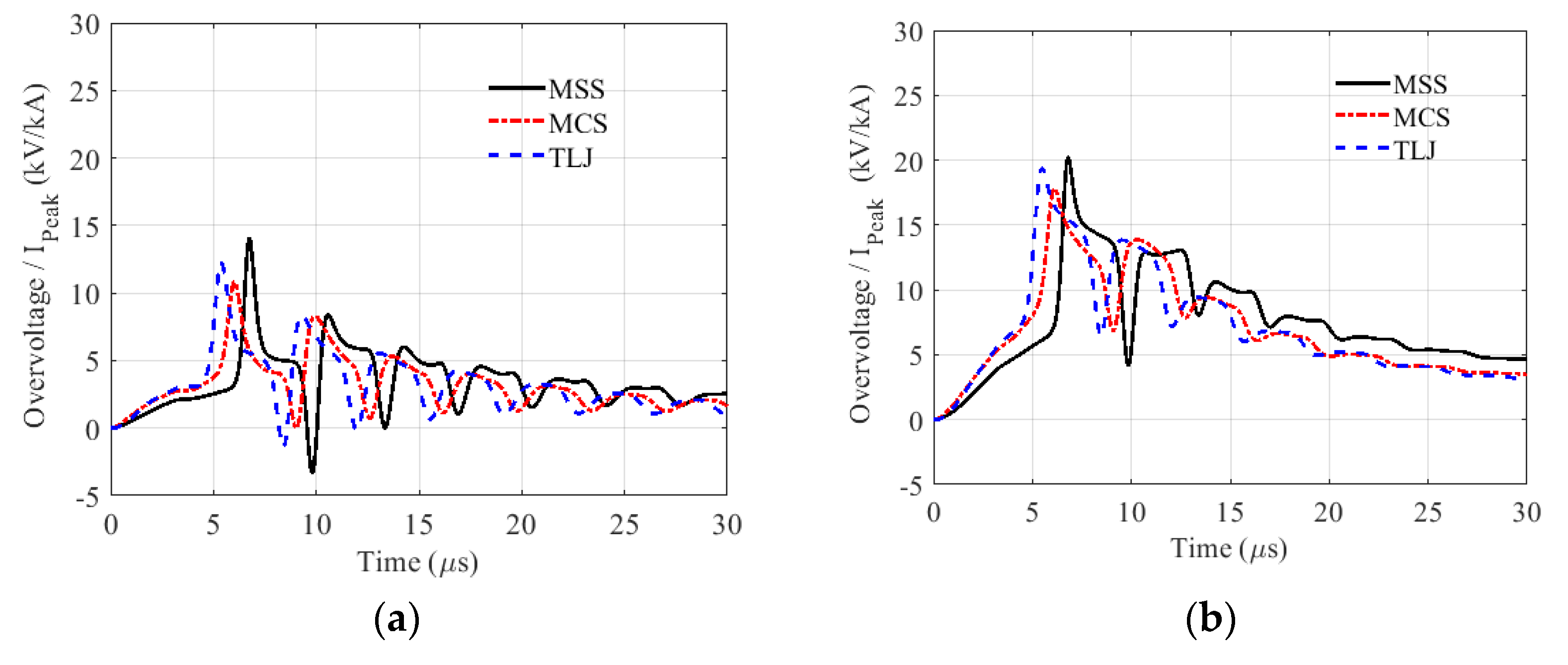
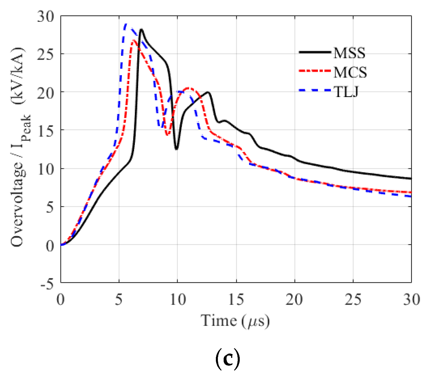
Figure 5 shows typical overvoltage waveforms across the external insulators of the 230 kV line, considering the injection of the three representative first stroke current waveforms shown in Figure 4 at the tower top and assuming three different tower footing impedance values, namely (a) 10 Ω, (b) 30 Ω and (c) 60 Ω. To compare the overvoltage waveforms resulting from the injection of each lighting current, they were normalized in relation to the peak value of the corresponding current.
According to the results, the overvoltages associated with each lightning current present distinct waveforms, notably along their wavefront. This was somewhat expected since the current waveforms considered are characterized by different parameters and, therefore, also have different waveforms. Differences in overvoltage waveforms are observed for the three assumed tower footing impedance values, although they tend to converge with increasing tower footing impedance. Interestingly, as the tower footing impedance increases, the peak values of the normalized overvoltages also agree more closely. The results are presented here for the 230 kV line, but similar conclusions can be drawn for the 138 kV and 500 kV lines.

6.2. Critical Currents

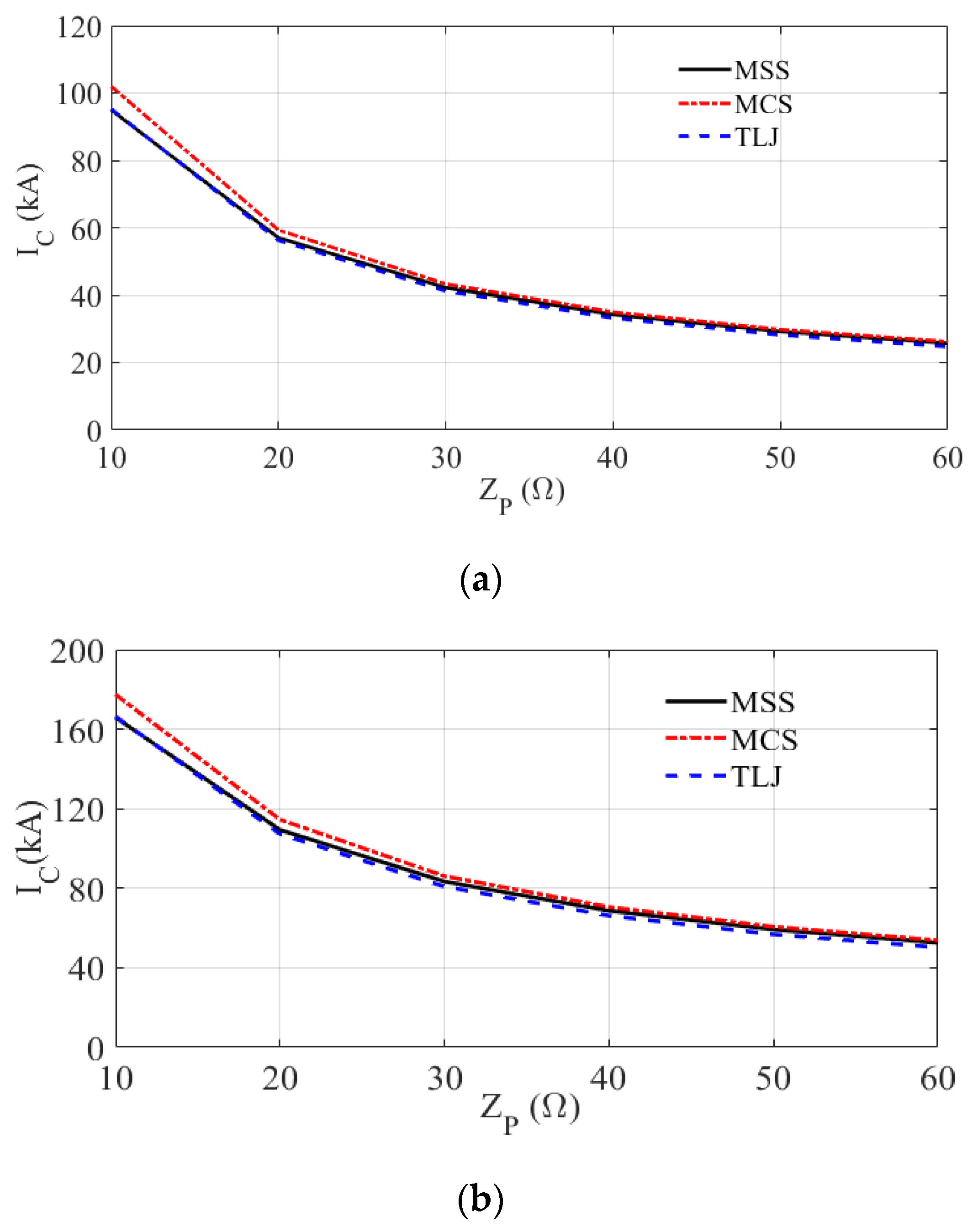
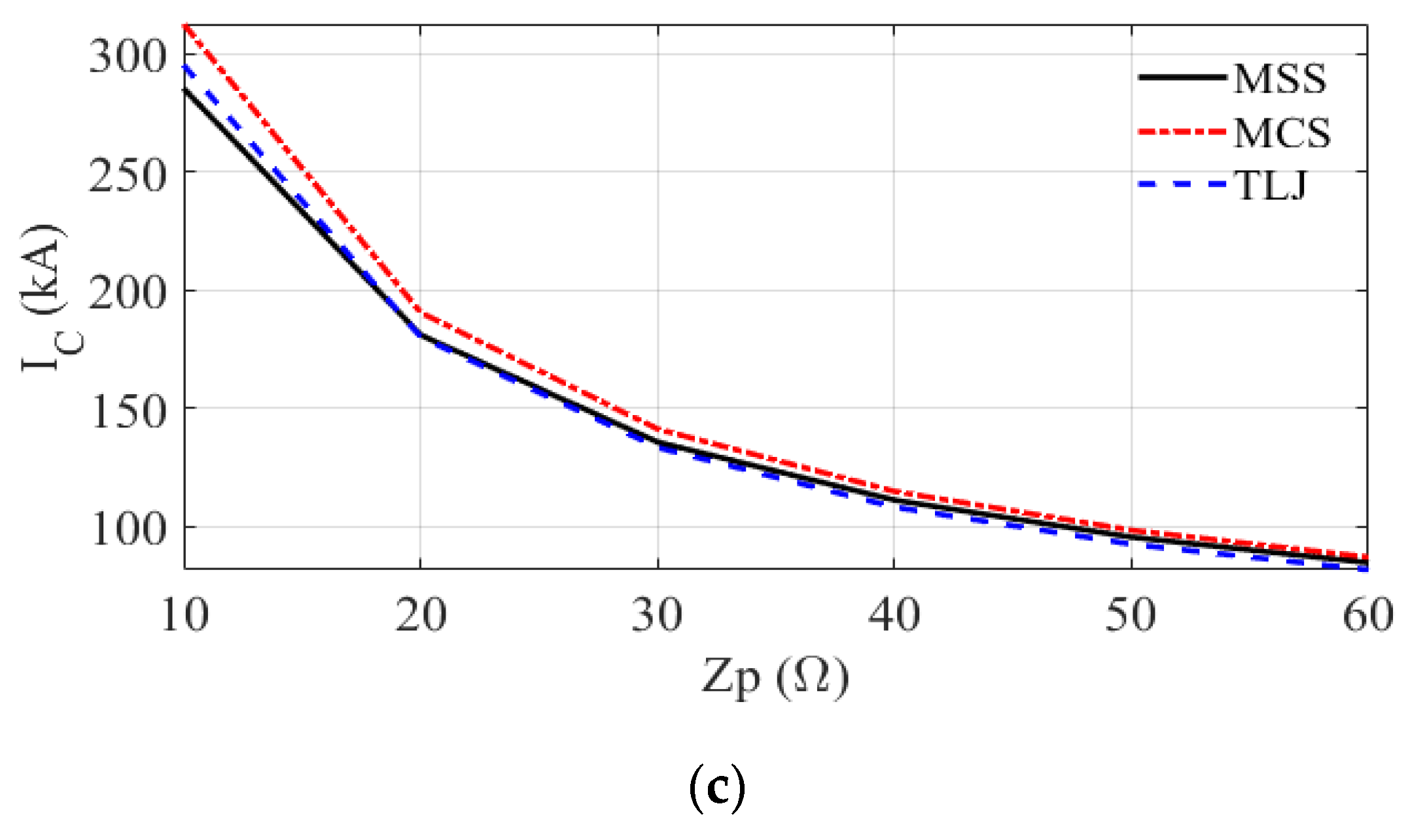
Figure 6a–c show the critical currents for tower footing impedance varying from 10 Ω to 60 Ω, for the 138 kV, 230 kV and 500 kV lines, respectively. The results consider the three representative first stroke current waveforms assuming measurements performed at Switzerland (MSS), Brazil (MCS) and Japan (TLJ). For each tower footing impedance and current waveform, the critical currents were determined by varying the current amplitude and assessing the disruptive effect associated with the resulting overvoltages across the lower phase insulator string of the 138 kV line and the external insulator strings of the 230 kV and 500 kV lines.
As expected, the critical current decreases as the tower footing impedance increases, irrespective of the line voltage level and the injected current waveform. As the impedance of the tower footing grounding system increases, its ability to mitigate the rise rate of impinging overvoltages across line insulators is diminished. This results in lower critical currents, meaning that lightning currents with smaller amplitudes can trigger flashovers. Comparatively, for the same tower footing impedance value, the 500 kV line (followed by the 230 kV line) exhibits higher critical currents than the 138 kV line, mainly due to the higher CFO values.
Figure 6 shows that the curves of critical current as a function of the tower footing impedance obtained considering the MSS and TLJ first stroke current waveforms agree closely, with the average percentage difference between them not exceeding 3%. This useful finding holds for the three analyzed TLs, despite the observed differences in the resulting overvoltages across the insulator strings for injection of the MSS and TLJ currents, as shown in Figure 5. For the MCS, higher values of critical current are obtained for lower tower footing impedance values; however, for Z P values greater than 20 Ω, the critical current curves obtained for the MCS current nearly match those obtained considering the MSS and TJL currents, with the average percentage difference between them not exceeding 5%. This result, that the critical currents obtained are not sensitive to the current waveforms used, increases the importance of the adopted cumulative peak current distribution for computing the TL outage rate.

6.3. Backflashover Rate: Influence of the Adopted CCD to Determine P I P > I c r i t

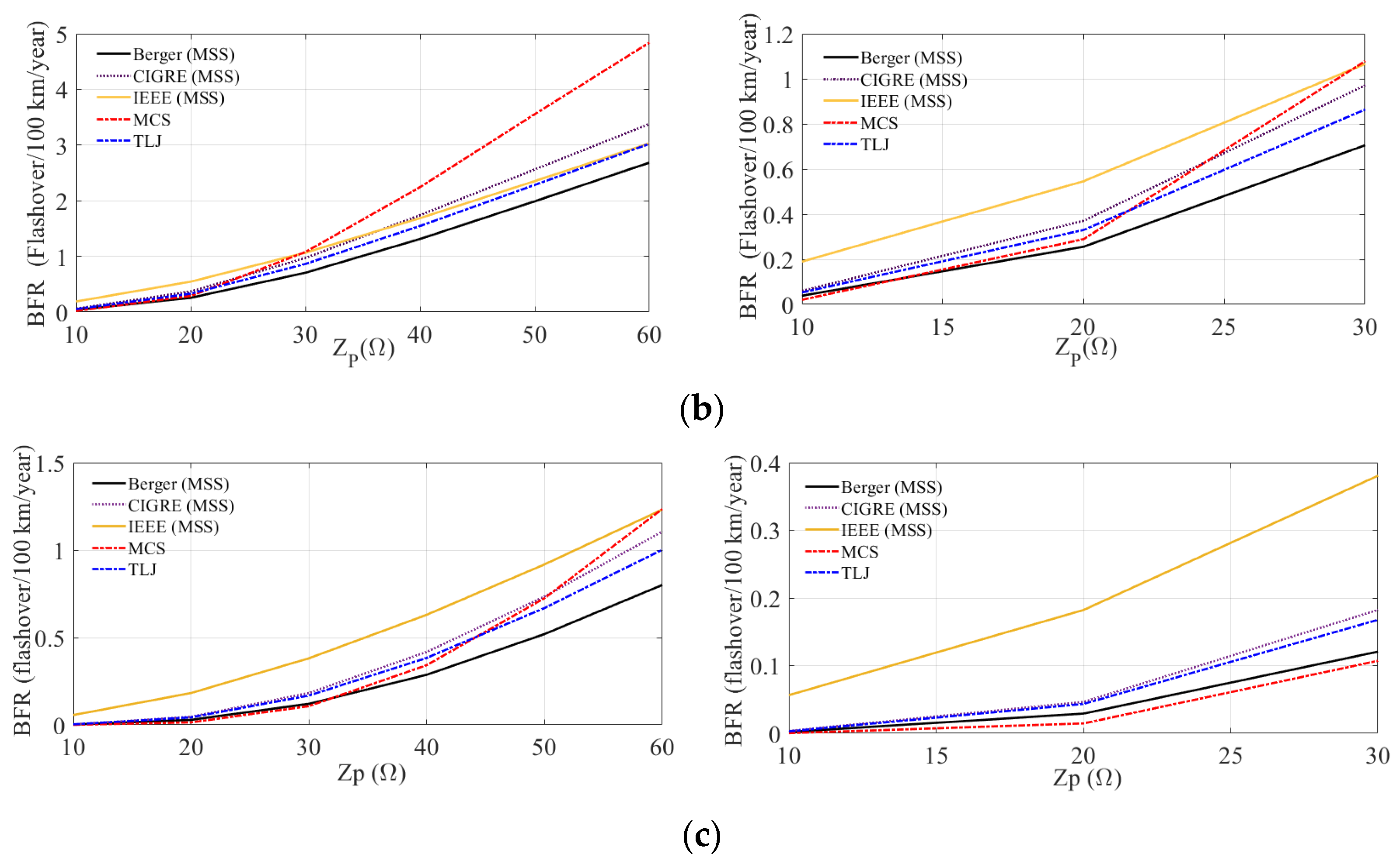
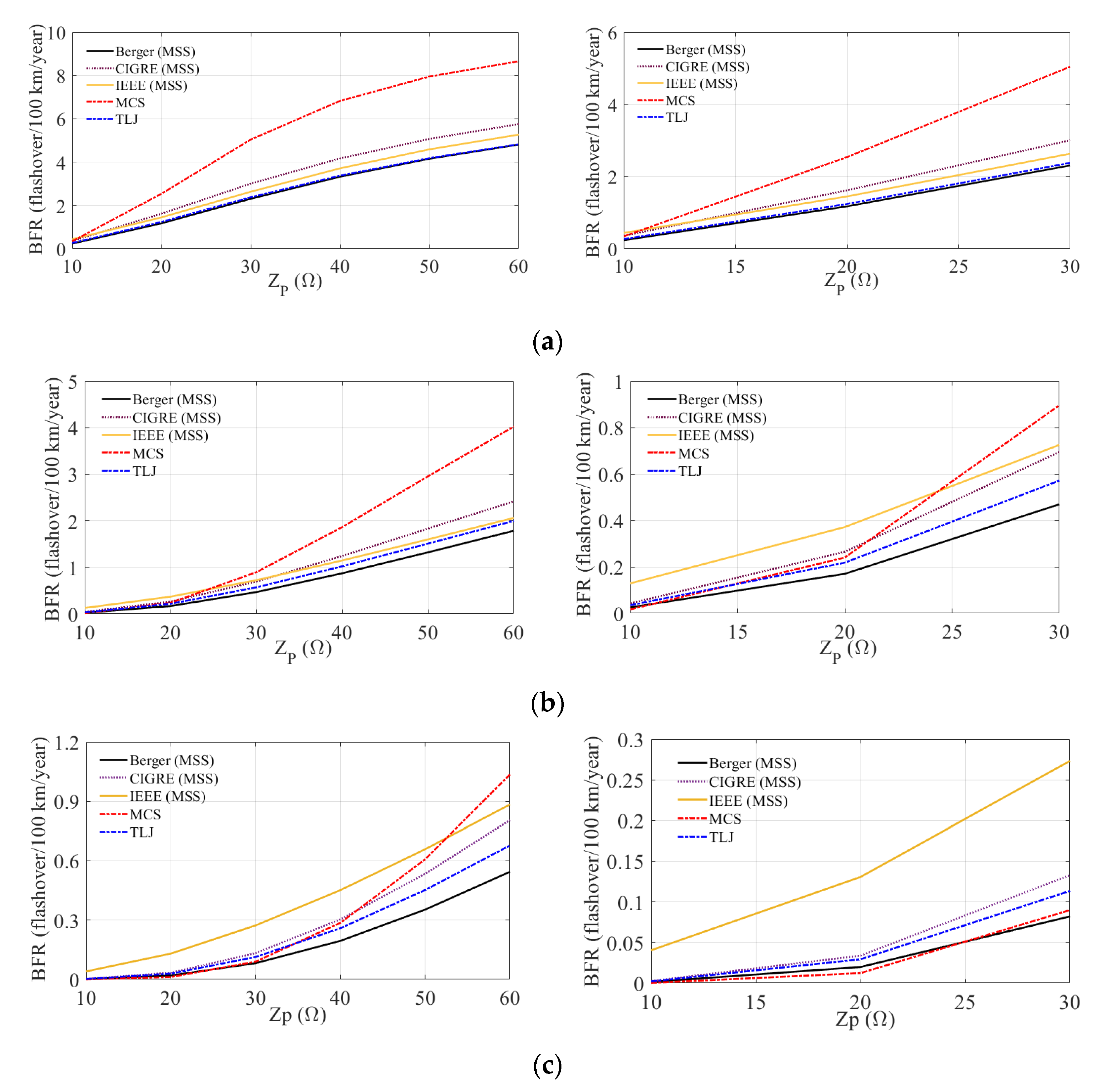
Based on the critical currents obtained, the annual number of outages caused by backflashover per 100 km of the 138 kV, 230 kV and 500 kV lines can be estimated using Equation (1). In these analyses, we consider the widely used concept of the average attractive radius to calculate the annual number of flashes to the line, denoted as N T L . The results of the backflashover rate as a function of Z P are presented in Figure 7a–c, respectively, for the 138 kV, 230 kV and 500 kV lines, considering different CCDs.
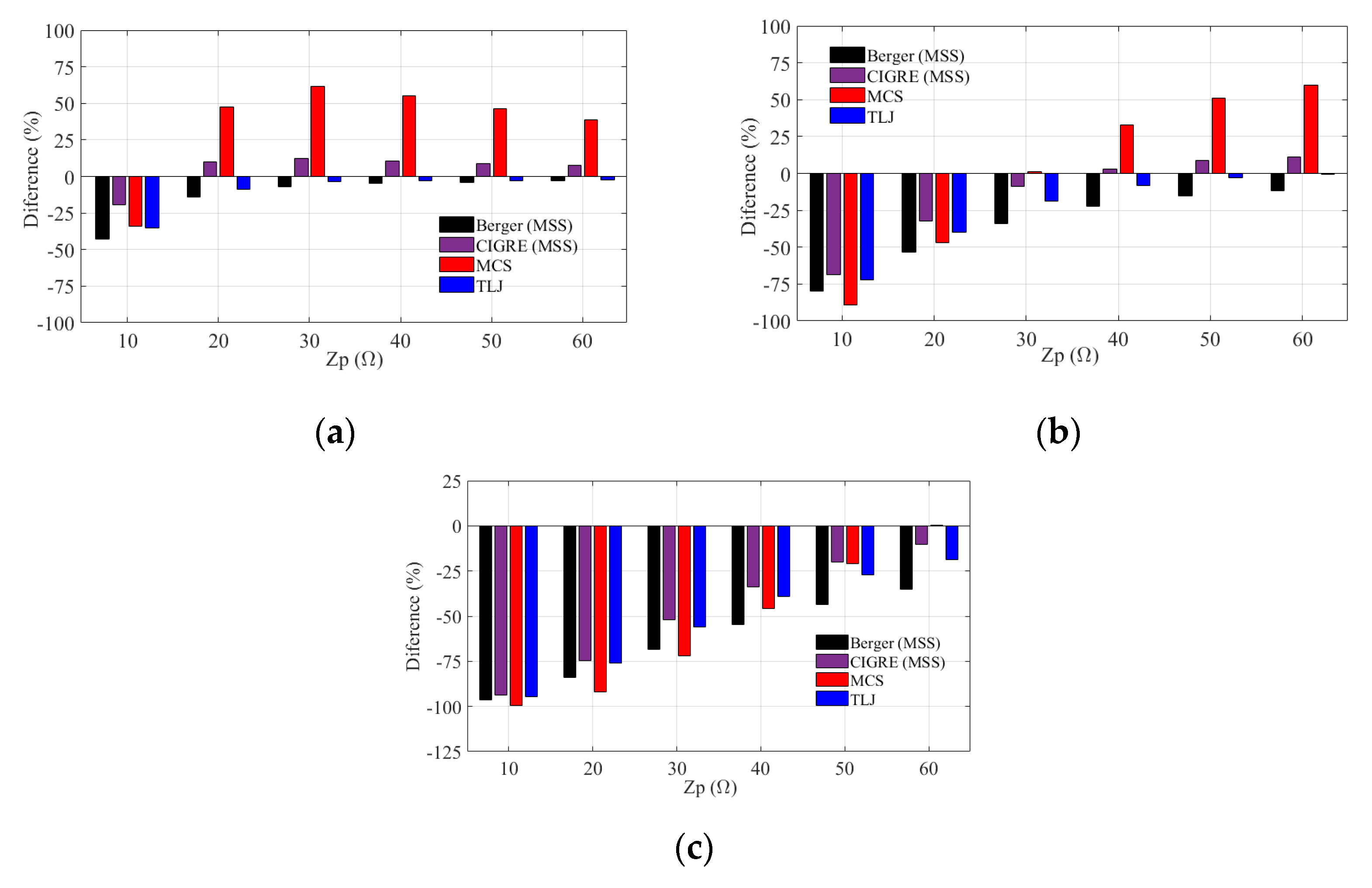
As seen, regardless of the cumulative current distribution, the B F R generally increases with the increase in the tower footing impedance, and even higher outage rates are observed for the 138 kV line due to its lower CFO. On the other hand, for a given value of tower footing impedance, the relationship between the determined outage rates considering the different CCDs depends on the voltage level of the TL. This is primarily linked to the variations in the probabilities of the critical current being surpassed, which are contingent upon the assumed CCD, as shown in Figure 1, since the number of flashes to the line is CCD-independent when using the concept of average attractive radius. To further explore these results, Figure 8a–c depict the differences in the estimated BFRs for each value of tower footing impedance taking the IEEE distribution as a reference, respectively, for the 138 kV, 230 kV and 500 kV lines.
For the 138 kV line, it is seen that for the 10-Ω Z P value, the IEEE distribution leads to higher BFRs in comparison with all the other peak current distributions. This is because for this value of tower footing impedance, the critical current is approximately 100 kA and, according to Figure 1, for currents greater than about 90 kA the IEEE distribution leads to higher probabilities in comparison with the other distributions. For tower footing impedance values between 20 Ω and 60 Ω, the estimated BFRs using MCS and CIGRE distributions are higher than those obtained using the IEEE distribution, since the critical currents vary between about 60 kA and 25 kA and, in this range of currents, both MCS and CIGRE distributions predict higher probabilities of the current being exceeded in comparison with the IEEE distribution. Differences up to 60% in the estimated BFR are observed when using the MCS distribution. A similar reasoning explains the lower outage rates obtained when using Berger (MSS) and TLJ distributions, although the differences in comparison with the results obtained using the IEEE distribution are less significant, especially for higher values of tower footing impedance.
Considering the 500 kV line, a quite different behavior is observed. It is seen that the estimated BFRs using the IEEE distribution are greater than those estimated using all other distributions over the considered range of tower footing impedance values. This stems from the fact that, given the higher CFO of the 500 kV line, the critical currents are consequently larger and located in the range where the IEEE distribution predicts a greater probability of them being exceeded. According to Figure 8c, although the differences tend to decrease with the increase in the tower footing impedance, they show high values and remain above 50% for Z P values between 10 Ω and 30 Ω.
The results found for the 230 kV line show an intermediate behavior between those observed for the 138 kV and 500 kV lines.

6.4. The Impact of the CCD on the Annual Number of Flashes to the Line ( N T L )

The results presented in the preceding section were obtained utilizing Eriksson’s concept of the average attractive radius [23,50] to compute the number of flashes to the line using (9). However, in practical scenarios, it becomes evident that the attractive radii exhibited by structures will vary from one stroke to another, contingent upon the relative peak value of the return stroke current and, ultimately, the probability of this value occurring [1,3,24]. In order to explore this dependency, Figure 9 illustrates the annual number of flashes to the 230 kV line using the average attractive radius concept, and taking into account each CCD and Equation (7). To compose the graphs, typical tower heights between 31.05 m and 43.05 m were assumed.
Figure 9 clearly shows that the annual number of flashes to the 230 kV line depends on the CCD. Similar conceptual results were obtained for the 138 kV and 500 kV lines, which are not shown here for brevity. A higher number of flashes to the line is expected assuming the MCS distribution, followed by CIGRE and IEEE distributions which lead to similar estimates. Berger (MSS) and TLJ distributions predict very similar values of N T L and a lower expectation of lightning incidence to the TL in comparison with the other distributions. Finally, it is seen that the concept of average attractive radius predicts more flashes to the line, in comparison with the use of (7) and considering the distinct current peak distributions. For a tower height of 37.05 m, the use of the average attractive radius leads to an estimate of N T L 17%, 28.5%, 29.6%, 33.5% and 34% greater than that obtained considering MCS, CIGRE, IEEE, Berger and TLJ distributions, respectively. As detailed in Section 4, the average attractive radius concept considers an average peak current value of 35 kA to compute the number of flashes to the line, disregarding the statistical nature of this parameter. According to the results of Figure 9, this approach leads to conservative results, meaning it estimates a higher number of annual flashes to the line compared to the more rigorous approach that accounts for the effect of the cumulative distribution of the peak current.
To gain deeper insights into the impact of the peak current distribution on the calculated number of flashes to the line, Figure 10a shows the product N T L p ( I P > I c r i t ) —see (1)—as a function of the peak current considering the concept of average attractive radius, while Figure 10b shows the same but considering the number of flashes to the line obtained from (7). The curves were obtained for the 230 kV line and assuming a 37.05-m high tower. According to Figure 10a, it is seen that the curves associated with the distinct CCDs cross each other at the same current values (90 kA) observed in Figure 1. As anticipated, the curves in Figure 10a remain identical to those in Figure 1, with the exception of a constant factor. This is because, when using the concept of average attractive radius, the number of flashes to the line becomes independent of the CCD. However, when considering the annual number of flashes to the line computed from Equation (7), Figure 10b illustrates that the crossing between the curves associated with IEEE and MCS distributions now takes place at approximately 100 kA, rather than 90 kA as observed in Figure 10a. This occurs due to the consideration of the CCD’s influence on the lightning incidence to the TL, which results in a higher number of expected flashes for the MCS distribution. Additionally, the intersections of the MCS curve with the curves associated with CIGRE, MSS and TLJ distributions are shifted to the right compared to Figure 10a.

6.5. Simultaneous Influence of the Adopted Cumulative Current Distribution to Determine P I P > I c r i t and N T L

In this section, we assess the backflashover rates of the three TLs while considering the impact of the adopted CCD on determining both the probability of the critical current being exceeded and the annual number of flashes to the line. The results obtained are illustrated in Figure 11 for the (a) 138 kV, (b) 230 kV and (c) 500 kV lines.
The general behavior of the results in Figure 11 is similar to the results shown in Figure 7, which were obtained using the concept of average attractive radius, i.e., the BFR increases with the tower footing impedance, and higher outage rates are observed for the 138 kV line due to its lower CFO. On the other hand, considering the influence of CCD on the number of flashes to the line leads to lower values of BFR in comparison with average attractive radius, in line with the findings detailed in the previous section.
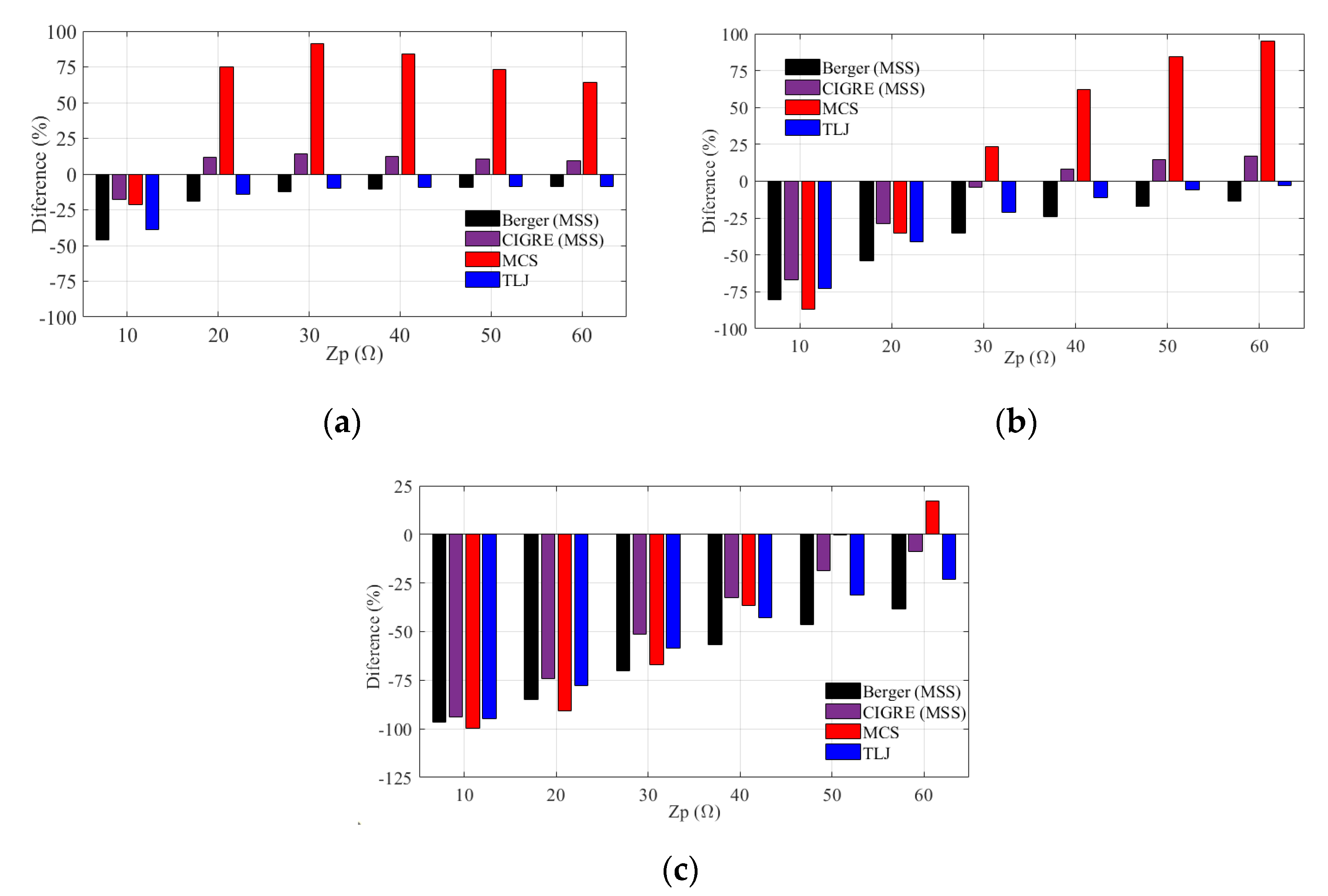
Figure 12 illustrates the variations in the estimated BFRs for each value of tower footing impedance, with the IEEE distribution serving as the reference. The analysis is conducted for the (a) 138 kV, (b) 230 kV and (c) 500 kV lines. When comparing the results obtained for the 138 kV and 230 kV lines (Figure 12a,b) with Figure 8a,b, a similar overall trend is observed. However, more significant differences emerge between the results obtained using IEEE distribution and those obtained from CIGRE and MCS distributions when the influence of the CCD on the number of flashes to the line is taken into account. Considering the results obtained for the 500 kV line, comparing Figure 8c and Figure 12c, again a similar behavior is observed, although with an important difference. Using the concept of average attractive radius, the estimated BFRs using the IEEE distribution are higher compared to using all other CCDs considered. On the other hand, considering the impact of the CCD on the annual number of flashes to the line, using the MCS distribution leads to larger backflashover rates in the case of higher tower footing grounding impedances. Although this situation is not expected to be prevalent along the TL route, it may occur in certain sections. This will affect the TL outage rate computation and is considered by dividing the line into sections of log-normal distribution of tower footing impedance values.
Ultimately, the findings presented in this section underscore the significance of accurately considering the impact of the CCD when estimating both the probability of the critical current being surpassed and determining the annual number of flashes to the line.

7. Summary and Conclusions

This study provides a comprehensive assessment of how the cumulative peak current distribution influences the evaluation of lightning performance in terms of the backflashover outage rate for transmission lines. We considered a range of distributions, including instrumented tower data from MSS, MCS and TLJ, as well as standard distributions from IEEE and CIGRE. The analysis encompassed three transmission lines of different voltage levels: 138 kV, 230 kV and 500 kV. The backflashover rates were computed by analyzing the overvoltages across line insulators resulting from the injection of representative first negative return stroke currents measured at instrumented towers. Based on the obtained results, the following conclusions can be drawn.
(1)
The estimated values of critical current leading to line flashover from simulations considering the injection of three representative first negative stroke current waveforms assuming measurements performed in Switzerland (MSS), Brazil (MCS) and Japan (TLJ) were reasonably similar, despite the observed differences in the overvoltage waveforms associated with each lightning current. This reinforces the importance of choosing the appropriate CCD to compute the probability of the critical current being exceeded and, ultimately, to estimate the backflashover rate.
(2)
Typically, in the calculation of line backflashover outage rate, the CCD is considered only in the computation of the probability of the critical current being exceeded, p(Ip > Icrit). However, the adopted CCD also influences the determination of the annual number of flashes to the line, NTL. Therefore, in accurate analysis of lightning performance of TLs, the CCD should be considered in determining both p(Ip > Icrit) and NTL.
(3)
The concept of average attractive radius, widely used to compute the number of flashes to the line, assumes an average peak current value and disregards the statistical nature of this parameter. The use of this concept overestimates the number of annual flashes to the line compared to the approach that considers the influence of the cumulative current distribution. This result held true for all the cumulative current distributions considered in this paper.
(4)
Considering the three analyzed TLs, the use of the standard IEEE and CIGRE distributions leads to higher BFRs in comparison with instrumented tower MSS and TLJ distributions. This result holds for the 500 kV TL considering the MCS distribution and assuming tower footing grounding impedances up to around 40 Ω. However, for the 138 kV and 230 kV lines, the MCS distribution leads to higher backflashover rates as the tower footing impedance increases, notably in the case of the 138 kV line. Depending on the TL voltage level and on the tower footing impedance value, the differences between the estimated BFR using instrumented tower or standard distributions can be greater than 50%. This strongly reinforces the importance of using, whenever available, local cumulative peak current distributions obtained from measurements in instrumented towers to obtain more realistic outage rates consistent with the region in which the TL is installed.
(5)
If the TL is not located in a tropical region and local cumulative peak current distributions are not available, the use of the standard IEEE and CIGRE distributions is recommended as they lead to conservative estimates of the backflashover rate.
(6)
For higher voltage level TLs, the critical current can often exceed 100 kA. In this case, special care must be taken in the adopted assumptions for TL performance computation, since, of the three instrumented tower distributions considered in this paper, only the MCS and TLJ distributions contain measured values above 100 kA. This reinforces the need for a greater number of measurements on instrumented towers around the world, aiming at reducing the uncertainty at both ends of the cumulative peak current distributions.

Author Contributions

Conceptualization, D.C. and R.A.; Methodology, D.C. and R.A.; Validation, D.C. and R.A.; Formal analysis, D.C., R.A., I.J.S.L. and W.C.; Investigation, D.C., R.A. and W.C.; Resources, D.C. and R.A.; Data curation, D.C., I.J.S.L. and W.C.; Writing—original draft, D.C.; Writing—review & editing, D.C., R.A., I.J.S.L. and W.C.; Supervision, R.A. All authors have read and agreed to the published version of the manuscript.

Funding

This work has been supported by the Brazilian agency CAPES. This paper was also supported by the National Council for Scientific and Technological Development (CNPq) under grant 314849/2021-1.

Data Availability Statement

Not applicable.

Conflicts of Interest

The authors declare no conflict of interest.

References

  1. Working Group C4.23. CIGRE TB 839: Procedures for Estimating the Lightning Performance of Transmission Lines—New Aspects; CIGRÉ: Paris, France, 2021; ISBN 9782858735440. [Google Scholar]
  2. Bucolo, M.; Buscarino, A.; Famoso, C.; Fortuna, L. Chaos Addresses Energy in Networks of Electrical Oscillators. IEEE Access 2021, 9, 153258–153265. [Google Scholar] [CrossRef]
  3. CIGRÉ TB 549; Lightning Parameters for Engineering Applications. CIGRÉ: Paris, France, 2013.
  4. Std 1243-1997; Transmission and Distribution Committee. Guide for Improving the Lightning Performance of Transmission Lines. IEEE Power Engineering Society: New York, NY, USA, 1997; ISBN 1559379375.
  5. International Electrotechnical Commission (IEC). IEC 60099—Surge Arresters; IEC: Geneva, Switzerland, 2018. [Google Scholar]
  6. Datsios, Z.G.; Ioannidis, A.I.; Papadopoulos, T.A.; Tsovilis, T.E. A Stochastic Model for Evaluating the Lightning Performance of a −400 kV HVDC Overhead Line. IEEE Trans. Electromagn. Compat. 2021, 63, 1433–1443. [Google Scholar] [CrossRef]
  7. Datsios, Z.G.; Mikropoulos, P.N.; Tsovilis, T.E. Effects of Lightning Channel Equivalent Impedance on Lightning Performance of Overhead Transmission Lines. IEEE Trans. Electromagn. Compat. 2019, 61, 623–630. [Google Scholar] [CrossRef]
  8. Gatta, F.M.; Geri, A.; Lauria, S.; Maccioni, M.; Palone, F. Tower grounding improvement versus line surge arresters: Comparison of remedial measures for high-Bfor subtransmission lines. IEEE Trans. Ind. Appl. 2015, 51, 4952–4960. [Google Scholar] [CrossRef] [Green Version]
  9. Alemi, M.R.; Sheshyekani, K. Wide-band modeling of tower-footing grounding systems for the evaluation of lightning performance of transmission lines. IEEE Trans. Electromagn. Compat. 2015, 57, 1627–1636. [Google Scholar] [CrossRef]
  10. Shariatinasab, R.; Gholinezhad, J.; Sheshyekani, K.; Alemi, M.R. The effect of wide band modeling of tower-footing grounding system on the lightning performance of transmission lines: A probabilistic evaluation. Electr. Power Syst. Res. 2016, 141, 1–10. [Google Scholar] [CrossRef]
  11. Datsios, Z.G.; Mikropoulos, P.N.; Tsovilis, T.E. Estimation of the minimum shielding failure current causing flashover in overhead lines of the hellenic transmission system through ATP-EMTP simulations. Int. Colloq. Light. Power Syst. 2016. [Google Scholar] [CrossRef]
  12. Mikropoulos, P.N.; Tsovilis, T.E. Estimation of the Shielding Performance of Overhead Transmission Lines: The Effects of Lightning Attachment Model and Lightning Crest Current Distribution. IEEE Trans. Dielectr. Electr. Insul. 2012, 19, 2155–2164. [Google Scholar] [CrossRef]
  13. Martinez, J.A.; Castro-Aranda, F. Lightning performance analysis of overhead transmission lines using the EMTP. IEEE Trans. Power Deliv. 2005, 20, 2200–2210. [Google Scholar] [CrossRef]
  14. Assis, S.C.; Boaventura, W.C.; Paulino, J.O.S. Lightning Performance of Transmission Line: Comparison IEEE Flash and Monte Carlo Method. IEEE Lat. Am. Trans. 2017, 15, 269–274. [Google Scholar] [CrossRef]
  15. Mikropoulos, P.N.; Tsovilis, T.E. Estimation of lightning incidence to overhead transmission lines. IEEE Trans. Power Deliv. 2010, 25, 1855–1865. [Google Scholar] [CrossRef]
  16. He, J.; Wang, X.; Yu, Z.; Zeng, R. Statistical analysis on lightning performance of transmission lines in several regions of China. IEEE Trans. Power Deliv. 2015, 30, 1543–1551. [Google Scholar] [CrossRef]
  17. Berger, K.; Anderson, R.B.; Kroninger, H. Parameters of lightning flashes. Electra 1975, 41, 223–237. [Google Scholar]
  18. Anderson, J.G. Lightning Performance of Transmission Lines. In Transmission line Reference Book, 345 kV and above; EPRI-Electric Power Research Institute, Ed.; Electric Power Research Institute (EPRI): Palo Alto, CA, USA, 1982; pp. 545–597. [Google Scholar]
  19. Popolansky, F. Frequency Distribution of Amplitudes of Lightning Currents. Electra 1972, 22, 139–147. [Google Scholar]
  20. Anderson, R.B.; Eriksson, A.J. Lightning Parameters for Engineering Application. Electra 1980, 69, 65–102. [Google Scholar]
  21. Conceição, D.; Lopes, I.J.S.; Alipio, R. An Investigation into the Effect of the Probabilistic Distribution of Lightning Current Amplitude on a Transmission Line Backflashover Rate. In Proceedings of the 35th International Conference on Lightning Protection/XVI International Symposium on Lightning Protection, Colombo, Sri Lanka, 20–26 September 2021. [Google Scholar]
  22. Silveira, F.H.; Almeida, F.S.; Visacro, S. Assessing the influence of peak current distributions of first return strokes on the lightning performance of transmission lines: Instrumented tower distributions versus standard distributions. Electr. Power Syst. Res. 2023, 214, 108822. [Google Scholar] [CrossRef]
  23. Eriksson, A.J. The Incidence of Lightning Strikes to Power Lines. IEEE Power Eng. Rev. 1987, 66–67. [Google Scholar] [CrossRef]
  24. Working Group 01 (Lightning)—Study Committee 33 (Overvoltages and Insulation Coordination) CIGRE TB 63: Guide to Procedures for Estimating the Lightning Performance of Transmission Lines. CIGRE Rep. 1991, 63, 1–64.
  25. Sargent, M.A. The Frequency Distribution of Current Magnitudes of Lightning Strokes to Tall Structures. IEEE Trans. Power Appar. Syst. 1972, 91, 2224–2229. [Google Scholar] [CrossRef]
  26. Mousa, A.M.; Srivastava, K.D. The Implications of the Electrogeometric Model Regarding Effect of Height of Structure on the Median Amplitudes of Collected Lightning Strokes. IEEE Trans. Power Deliv. 1989, 4, 1450–1460. [Google Scholar] [CrossRef]
  27. Borghetti, A.; Nucci, C.A.; Paolone, M. Estimation of the Statistical Distributions of Lightning Current Parameters at Ground Level from the Data Recorded by Instrumented Towers. IEEE Trans. Power Deliv. 2004, 19, 1400–1409. [Google Scholar] [CrossRef]
  28. AIEE Committee Report. A Method of Estimating Lightning Performance of Transmission Lines. Trans. Am. Inst. Electr. Eng. 1950, 69, 1187–1196.
  29. Bao, J.; Wang, X.; Zheng, Y.; Zhang, F.; Huang, X.; Sun, P. Lightning Performance Evaluation of Transmission Line Based on Data-Driven Lightning Identification, Tracking, and Analysis. IEEE Trans. Electromag-Netic Compat. 2021, 63, 160–171. [Google Scholar] [CrossRef]
  30. de Castro Assis, S.; do Couto Boaventura, W.; Paulino, J.O.S.; Markiewicz, R.L. Lightning Performance of Transmission Line with and without Surge Arresters: Comparison between a Monte Carlo method and field experience. Electr. Power Syst. Res. 2017, 149, 169–177. [Google Scholar] [CrossRef]
  31. Koehler, F.; Swingler, J. Simplified Analytical Representation of Lightning Strike Waveshapes. IEEE Trans. Electromagn. Compat. 2016, 58, 153–160. [Google Scholar] [CrossRef]
  32. de Vasconcelos, J.A.; Teixeira, D.A.; Ribeiro MF, D.O. Optimal Selection and Arrangement of Cables for Compact Overhead Transmission Lines of 138/230 kV. IEEE Lat. Am. Trans. 2017, 15, 1460–1466. [Google Scholar] [CrossRef]
  33. Paolone, M.; Rachidi-Haeri, F.; Nucci, C.A. IEEE Guide for Improving the Lightning Performance of Electric Power Overhead Distribution Lines; IEEE: New York, NY, USA, 2011; Volume 2010, ISBN 9780738164878. [Google Scholar]
  34. Shariatinasab, R.; Vahidi, B.; Hosseinian, S.H.; Ametani, A. Probabilistic evaluation of optimal location of surge arresters on EHV and UHV networks due to switching and lightning surges. IEEE Trans. Power Deliv. 2009, 24, 1903–1911. [Google Scholar] [CrossRef]
  35. Takami, J.; Okabe, S. Observational results of lightning current on transmission towers. IEEE Trans. Power Deliv. 2007, 22, 547–556. [Google Scholar] [CrossRef]
  36. Silveira, F.H.; Visacro, S. Lightning Parameters of a Tropical Region for Engineering Application: Statistics of 51 Flashes Measured at Morro do Cachimbo and Expressions for Peak Current Distributions. IEEE Trans. Electromagn. Compat. 2019, 62, 1369. [Google Scholar] [CrossRef]
  37. EMTP User Group. Alternative Transients Program (ATP): Rule Book; Leuven EMTP Center: Leuven, Belgium, 1987. [Google Scholar]
  38. Dommel, H.W. Electromagnetic Transients Program. Reference Manual (EMTP Theory Book). Portland: Bonneville Power Administration; Bonneville Power Administration: Portland, OR, USA, 1986. [Google Scholar]
  39. CIGRE SC C4 (Working Group C4.26). Evaluation of lightning shielding analysis methods for EHV and UHV DC and AC transmission lines—Technical Brochure No. 704 2017. Electra 2017, 39–43. [Google Scholar]
  40. Golde, R.H. The Frequency of Occurrence and the Distribution of Lightning Flashes to Transmission Lines. AIEE Trans. 1945, 64, 902–910. [Google Scholar]
  41. Wagner, C.F.; Hileman, A.R. A New Approach to Calculation of Lightning Performance of Transmission Lines—II. Trans. Am. Inst. Electr. Eng. 1959, 78, 996–1020. [Google Scholar] [CrossRef]
  42. Wagner, C.F.; Hileman, A.R. Lightning performance of transmission lines—III. Electr. Eng. 1960, 79, 589–603. [Google Scholar] [CrossRef]
  43. Wagner, C.F.; Hileman, A.R. A New Approach to the Calculation or the Lightning Perrormance or Transmission Lines III-A Simplified Method: Stroke to Tower. Trans. Am. Inst. Electr. Eng. 1960, 79, 589–603. [Google Scholar] [CrossRef]
  44. Armstrong, H.R.; Whitehead, E.R. A Lightning Stroke Pathfinder. IEEE Trans. Power Appar. Syst. 1964, 83, 1223–1227. [Google Scholar] [CrossRef]
  45. Armstrong, H.R.; Whitehead, E.R. Field and Analytical Studies of Transmission Line Shielding. IEEE Trans. Power Appar. Syst. 1968, 87, 270–281. [Google Scholar] [CrossRef]
  46. Dellera, L.; Garbagnati, E. Lightning stroke simulation by means of the leader progression model. II. Exposure and shielding failure evaluation of overhead lines with assessment of application graphs. IEEE Trans. Power Deliv. 1990, 5, 2023–2029. [Google Scholar] [CrossRef]
  47. Dellera, L.; Garbagnati, E. Lightning Stroke Simulation by Means of the Leader Progression Model. Part I: Description of the model and evaluation of exposure of free-standing structures. IEEE Trans. Power Deliv. 1990, 5, 2009–2022. [Google Scholar] [CrossRef]
  48. Rizk, F.A.M. Modeling of Transmission Line Exposure to Direct Lightning Strokes. IEEE Trans. Power Deliv. 1990, 5, 1983–1997. [Google Scholar] [CrossRef] [Green Version]
  49. Eriksson, A.J. Lightning and Tall Structures. Trans. South African Inst. Electr. Eng. 1978, 69, 238–252. [Google Scholar]
  50. Eriksson, A.J. An Improved Electrogeometric Model for Transmission Line Shielding Analysis. IEEE Trans. Power Deliv. 1987, 2, 871–886. [Google Scholar] [CrossRef]
  51. Oliveira, A.J.; Schroeder, M.A.O.; Moura, R.A.R.; de Barros, M.T.C.; Lima, A.C.S. Adjustment of Current Waveform Parameters for First Lightning Strokes. In Proceedings of the International Symposium on Lightning Protection—XIV SIPDA, Natal, Brazil, 2–6 October 2017; pp. 121–126. [Google Scholar]
  52. de Conti, A.; Visacro, S. Analytical Representation of Single-and Double-Peaked Lightning Current Waveforms. IEEE Trans. Electromagn. Compat. 2007, 49, 448–451. [Google Scholar] [CrossRef]
  53. Rakov, V.A.; Uman, M.A. Lightning: Physics and Effects, 1st ed.; Cambridge University Press: Cambridge, UK, 2003. [Google Scholar]
  54. Guilherme, J.S.; Alipio, R. Impact of Subsequent Strokes on Backflashover Rate Revisited: Influence of the Accurate Representation of Tower-foot Grounding. In Proceedings of the 2022 36th International Conference on Lightning Protection (ICLP), Cape Town, South Africa, 2–7 October 2022; pp. 1–6. [Google Scholar]
  55. Conceição, D.; Lopes, I.J.S.; Alipio, R. An investigation into the impact of tower height variation on transmission line’ s backflashover rate considering different probability distributions. In Proceedings of the 36th International Conference on Lightning Protection—ICLP, Cape Town, South Africa, 2–7 October 2022. [Google Scholar]
  56. Conceição, D.; Alipio, R.; Chisholm, W.A.; Lopes, I.J.S. Lightning Performance Calculation of Transmission Lines Considering a Detailed Modeling of the Tower Geometries Distribution. In Proceedings of the International Conference on Grounding & Lightning Physics and Effects, Belo Horizonte, Brazil, 2–5 June 2021. [Google Scholar]
  57. De Conti, A.; Visacro, S.; Soares, A.; Schroeder, M.A.O. Revision, extension, and validation of Jordan’s formula to calculate the surge impedance of vertical conductors. IEEE Trans. Electromagn. Compat. 2006, 48, 530–536. [Google Scholar] [CrossRef]
  58. Vasconcellos, F.; Alípio, R.; Moreira, F. Evaluation of the Impact of Including the Frequency-Dependent Behavior of Grounding Systems on the Lightning Performance of Transmission Lines and on Grounding Systems Design. J. Control. Autom. Electr. Syst. 2022, 33, 531–540. [Google Scholar] [CrossRef]
  59. Martinez-Velasco, J.A. (Ed.) Power System Transients—Parameter Determination; CRC Press: Boca Raton, FL, USA, 2018. [Google Scholar]
  60. Alípio, R.; Visacro, S. Impulse Efficiency of Grounding Electrodes: Effect of Frequency-Dependent Soil Parameters. IEEE Trans. Power Deliv. 2014, 29, 716–723. [Google Scholar] [CrossRef]
  61. Visacro, S.; Silveira, F.H. Lightning Performance of Transmission Lines: Requirements of Tower-Footing Electrodes Consisting of Long Counterpoise Wires. IEEE Trans. Power Deliv. 2016, 31, 1524–1532. [Google Scholar] [CrossRef]
  62. Chisholm, W.A. New Challenges in Lightning Impulse and Insulators. IEEE Electr. Insul. Mag. 2010, 26, 14–25. [Google Scholar] [CrossRef]
Figure 1. Comparison between different cumulative peak current distributions (a) Range from 0 to 200 kA and probability 0 to 1. (b) Range from 80 to 200 kA and probability from 0 to 0.1.
Energies 16 05836 g001
Figure 2. (a) The 138 kV tower geometry; the sags of the phase cables and shield wires are respectively 11.20 m and 7.2 m. (b) The 230 kV tower geometry; the sags of the phase cables and shield wires are respectively 18.165 m and 14.44 m. (c) The 500 kV tower geometry; the sags of the phase cables and shield wires are respectively 21.17 m and 13.61 m.
Energies 16 05836 g002
Figure 3. Lateral attractive radius of a transmission line for a specific stroke peak current.
Energies 16 05836 g003
Figure 4. Representation of first stroke current waveforms.
Energies 16 05836 g004
Figure 5. Typical overvoltage waveforms across the external insulator of the 230 kV line, considering the injection of the lightning currents depicted in Figure 4 at the tower top and assuming tower footing impedances of (a) 10 Ω, (b) 30 Ω, (c) 60 Ω.
Energies 16 05836 g005aEnergies 16 05836 g005b
Figure 6. Critical current versus tower footing impedance for (a) 138 kV, (b) 230 kV and (c) 500 kV lines.
Energies 16 05836 g006aEnergies 16 05836 g006b
Figure 7. Backflashover rate for (a) 138 kV, (b) 230 kV, (c) 500 kV lines, considering the concept of average attractive radius and different CCDs. On the left, the graph considering impedances from 10 to 60 Ω, on the right a zoomed-in view considering impedances from 10 to 30 Ω.
Energies 16 05836 g007aEnergies 16 05836 g007b
Figure 8. Differences between the backflashover rates estimated considering the IEEE distribution compared to the use of different CCDs for (a) 138 kV, (b) 230 kV, (c) 500 kV lines.
Energies 16 05836 g008
Figure 9. Annual number of flashes to the 230 kV line assuming the concept of average attractive radius and considering the influence of different cumulative current distributions.
Energies 16 05836 g009
Figure 10. Product N T L p I P > I c r i t as a function of I P for the 230 kV line considering (a) the concept of average attractive radius to compute N T L and (b) the influence of CCD to compute N T L .
Energies 16 05836 g010aEnergies 16 05836 g010b
Figure 11. Backflashover for (a) 138 kV, (b) 230 kV, (c) 500 kV lines, considering the simultaneous influence of the CCDs. On the right, the graph considering impedances from 10 to 60 Ω, on the left a zoomed-in view considering impedances from 10 to 30 Ω.
Energies 16 05836 g011
Figure 12. Differences between the backflashover rates estimated considering the IEEE distribution compared to the use of different CCDs for (a) 138 kV, (b) 230 kV, (c) 500 kV lines.
Energies 16 05836 g012
Table 1. Parameters of the cumulative current distributions.
Distributions σ l n I P μ I P k A
Berger (MSS)0.610230
Morro do Cachimbo Station (MCS)0.4743.3
Takami and Okabe (TLJ)0.64429.3
CIGRE ( I c < 20   kA )
CIGRE ( I c 20   kA )
1.3361
0.60533.3
IEEE P I p = 1 1 + I p 31 2.6
Table 2. Conductor cable data.
PhaseShield Wire (3/8” EHS)
Conductors per PhaseRadius
(cm)
R d c ( / km ) Radius
(cm)
R d c ( / km )
138 kV11.4670.07180.4573.81
230 kV11.4670.07180.4573.81
500 kV41.4650.07110.4573.81
Table 3. Comparison of median parameters of first negative stroke currents measured at instrumented towers with data extracted from curves depicted in Figure 4.
DistributionsIp1Ip2Td30S30
(kA/μs)
T50Sm (kA/μs)
MSS27.831.03.87.27524.4
(27.7)(31.1)(3.8)(7.2)(75)(24.3)
0.36%0.32%0%0%0%0.4%
MCS37.943.34.2-50-
(37.6)(43.3)(4.2) (56.2)
0.79%0%0% 11%
TLJ27.629.63.28.538.619
(27.7)(29.3)(3.2)(8.8)(36.5)(18.9)
0.36%1%0%3%5.7%0.5%
Disclaimer/Publisher’s Note: The statements, opinions and data contained in all publications are solely those of the individual author(s) and contributor(s) and not of MDPI and/or the editor(s). MDPI and/or the editor(s) disclaim responsibility for any injury to people or property resulting from any ideas, methods, instructions or products referred to in the content.