Article

Experimental Investigation of the Improvement Potential of a Heat Pump Equipped with a Two-Phase Ejector

by
Wichean Singmai
1,2,
Kasemsil Onthong
1,2 and
Tongchana Thongtip
1,2,*
1
Advanced Refrigeration and Air Conditioning Laboratory (ARAC), Department of Teacher Training in Mechanical Engineering, King Mongkut’s University of Technology North Bangkok, Bangkok 10800, Thailand
2
Thermal and Fluid Laboratory (TFL), Department of Teacher Training in Mechanical Engineering, King Mongkut’s University of Technology North Bangkok, Bangkok 10800, Thailand
*
Author to whom correspondence should be addressed.
Energies 2023, 16(16), 5889; https://doi.org/10.3390/en16165889
Submission received: 12 June 2023 / Revised: 18 July 2023 / Accepted: 1 August 2023 / Published: 9 August 2023
(This article belongs to the Section J: Thermal Management)

Abstract

:
In this paper, an experimental investigation of the performance improvement of a heat pump equipped with a two-phase ejector, called an “ejector–expansion heat pump (EEHP)”, is proposed. The system performance of the EEHP is compared with that of a vapor-compression heat pump (VCHP). The improvement potential is determined and discussed. The heat pump test system based on a water-to-water heat pump that can experiment with both the EEHP and the VCHP is constructed. A two-phase ejector with a cooling load of up to 2500 W is installed for the experiment. The results show that the EEHP always produces a higher heating rate and COPHP than the VCHP under the specified working conditions. The heating COPHP is increased by 5.7–11.6% depending on the working conditions. It is also found that, under the same heat sink and heat source temperature, the EEHP can produce a lower compressor discharge temperature and a lower compressor pressure ratio than the VCHP. This is evidence that the two-phase ejector can provide the compressor with better working characteristics, which yields a longer compressor lifetime. It is demonstrated that the expansion pressure ratio is key to the performance of the EEHP. A larger expansion pressure ratio yields greater improvement potential when compared with the VCHP.

1. Introduction

For thermal processes, heat pumps play a significant role in producing hot water and other heating processes, such as air preheating, agricultural drying, or many of the heating processes used in industry. Heat pumps are thermal machines that provide better energy efficiency than electric heaters (which are widely used in thermal processes). Heat pumps can capture heat from low temperatures (the heat source) while, at the same time, producing the heating process at a higher temperature (the heat sink). Hence, they require a refrigeration system for operation.
Vapor-compression refrigeration systems are widely used as heat pumps. A mechanical compressor is used to drive the system, which requires electricity to produce a heating process, similarly to an electric heater. However, the efficiency of heat pumps can be higher than 100% (usually 250–420%), while that of electric heaters is close to 100%. This is because heat pumps use the working fluid (refrigerant) to produce heat under the desired conditions, which results in a COP as high as 2.5–4.2, as proposed by Huang et al. [1], Szymiczek et al. [2], Zhou et al. [3], Navarro et al. [4], and Trancossi et al. [5].
However, to operate a heat pump and produce a relatively high temperature and a high heating rate, the compressor must work hard. In such cases, the compressor discharge temperature is quite high, while, at the same time, the compressor pressure ratio is also quite large. Therefore, the heat pump’s working conditions are limited. For these reasons, many efforts have been made to improve various aspects of the heating performance [6,7,8,9,10,11]. Chiriboga et al. [12] and Lim et al. [13] proposed a geothermal-source heat pump that aimed to produce a heating temperature of 50–70 °C. Their technique was based on the fact that the available heat source temperature is quite high; hence, the compression pressure ratio of the compressor (PRcomp) is decreased, which results in lower electricity consumption and a lower compressor discharge temperature. Ye et al. [14], Leonzio et al. [15], and Wu et al. [16] proposed an air-source heat pump to produce hot water, which aimed to minimize electricity consumption via a lower compressor pressure ratio. However, even though the system is operated with a higher heat source temperature, the heat sink temperature (the main focus of any heat pump) was a problem due to the pump being operated at a higher temperature. Many researchers have focused on the development of the high-temperature compressor that can withstand larger pressure ratios and high discharge temperatures. Therefore, research based on vapor-injection heat pumps has been proposed.
Wu et al. [16], Huang et al. [17], Li et al. [18], Yang et al. [19], and Li et al. [20] developed the vapor-injection heat pump to operate at a relatively high temperature. The compressor was designed specifically to allow the low-temperature refrigerant vapor from the flash tank to be mixed with the refrigerant from the evaporator. Hence, it requires two expansion valves: first, it is used to produce the medium pressure of the refrigeration system (the conventional one has only high- and low-side pressure), and second, it is used to promote the refrigerating effect in the evaporator. Thus, part of the liquid refrigerant changes to vapor as it flows through the first expansion device. Later, only vapor is allowed through the compressor, which is developed specifically for this application, in which the low-temperature refrigerant can be mixed with the main refrigerant during the compression process. Hence, the temperature of the refrigerant discharge is reduced, which is advantageous to the compressor’s protection. However, the vapor-injection heat pump must be operated within a specified range of operating conditions so that the system’s COP can be higher than that of a conventional vapor-compression heat pump. In addition, it requires an optimal medium operating pressure to produce a higher heating rate. As a result, vapor-injection heat pumps have not gained popularity in this research area.
A promising technology that improves heat pump performance by mitigating throttling loss is made possible by installing a two-phase ejector. This is because heat pumps are mostly operated under a fairly high pressure ratio between the condenser and the evaporator. This produces quite a high cooling loss (i.e., lower heat absorption at the evaporator) via the throttling process due to the refrigerant’s phase transition. However, the heat pump operated with a two-phase ejector requires a vapor separator for phase separation. The system is then called an ejector–expansion heat pump (EEHP), as schematically shown in Figure 1. The figure clearly shows that the cycle operation of the EEHP is different from that of the conventional vapor-compression heat pump (VCHP). In this case, the liquefied refrigerant from the condenser outlet (state 3), known as the “primary fluid”, is expanded through the primary nozzle of the two-phase ejector. This causes a low-pressure region to be produced within the mixing chamber. Hence, low-pressure vapor from the evaporator (state 7), known as the “secondary fluid”, is conveyed into the mixing chamber and mixes with the primary fluid. The mass entrainment ratio (the ratio of the secondary mass flow rate to the primary mass flow rate) is a consequence of this process and constitutes an important parameter in the performance assessment of two-phase ejectors. The mixed fluid undergoes the pressure recovery process through the diffuser before entering the vapor separator at state 4. The saturated liquid at the bottom of the vapor separator re-enters the evaporator (state 5 to 6), while the saturated vapor at the top is sucked in by the compressor (state 1 to 2).
It is evident that the state of the refrigerant entering the evaporator is close to the saturated liquid state (the refrigerant quality is around 0.05–0.15), which is of lower quality than that of the conventional VCHP (the refrigerant quality is around 0.25–0.35). The EEHP yields a higher specific cooling load. At the same time, the compressor suction pressure of the EEHP is always higher than that of the VCHP, and the compressor pressure ratio of the EEHP is always lower than that of the VCHP. This generates a smaller amount of specific work. Therefore, installing the two-phase ejector benefits the overall system performance of the heat pump.
The previous research conducted by Boccardi et al. [21], Ghazizade-Ahsaee et al. [22], and Zhu et al. [23] concentrated on EEHPs that use carbon dioxide (CO2) as the working fluid because it is a natural refrigerant that is environmentally friendly and able to facilitate the heating process at relatively high temperatures. In addition, CO2 is used for the vapor-compression heat pump (VCHP) to produce a high-temperature heat sink. Therefore, an EEHP working with CO2 has been considered by many researchers to demonstrate the improvement potential of the EEHP compared to the VCHP, as discussed by Zhang et al. [24].
An EEHP working with CO2 must be operated at quite high working pressures; it also requires a high-pressure vessel and high-pressure fittings for piping work because of the thermodynamic properties of CO2. This results in high installation costs. Moreover, the working condensation temperature is based on trans-critical or supercritical pressures, a consequence of which is a fairly large expansion pressure ratio. Therefore, the two-phase ejector is widely used for heat pumps working with CO2. However, even though many researchers have focused on EEHPs working with CO2, they may not be suitable for large-scale operations. Therefore, the hot water or other heating processes produced by EEHPs working with CO2 may not be worth undertaking because of the economic aspects.
This problem has encouraged many researchers to develop heat pumps based on an alternative refrigerant that has a low GWP and a low ODP, as supported by Li et al. [25], Fan et al. [26], and Al-Sayyab et al. [27]. Their studies focused on using vapor-compression heat pumps to produce hot water or hot air for drying while the heat source is available from air sources, geothermal sources, and hot water produced by solar collectors. However, when working at a relatively high heat sink temperature, a system based on a VCHP must still be operated at a high expansion pressure ratio, which results in a high throttling loss. Thus, a two-phase ejector is installed to mitigate the expansion loss. This has encouraged some researchers to investigate EEHPs working with R1234yf, R404, or R407c with the aim of improving the cycle’s efficiency. However, experimental works that clearly explain the improvement potential of the EEHP compared to the VCHP are scarce, especially regarding the compressor’s working characteristics.
A previous work of the authors of this article (Sutthivirode and Thongtip, [28]) provided experimental evidence of the refrigeration improvement produced by an ejector–expansion refrigeration system (EERS), focusing on the cooling performance. Their interpretation showed that, in addition to COP improvements, the two-phase ejector could benefit the compressor’s working characteristics. In such a case, a much lower compressor discharge temperature is achieved by the EERS as compared with the conventional vapor-compression system (VCRS). Hence, it produces better compressor lubrication, which yields a longer compressor lifetime and improved compressor isentropic efficiency. Lower exergy destruction is made possible; this provides an exergoeconomic advantage, as supported by Zhang et al. [29] and Nemati et al. [30]. The impact of using a two-phase ejector on the compressor’s discharge temperature cannot be investigated in a theoretical study, and, thus, it requires an experimental proof. Moreover, it was found experimentally that the experimental COP of the EERS was not consistent with the theoretical COP. The theoretical COP was higher than the experimental COP. This is because the fluid property of the high-speed two-phase flow is quite difficult to determine correctly. In this case, non-equilibrium evaporation is involved, and, therefore, the heat and mass transfers during the phase transition, as well as the metastable effect, are believed to be the reason that the theoretical COP deviates from the experimentally determined COP. This means that experimental work is more reliable for performance assessments. Therefore, it would be beneficial to develop a more accurate design model of the two-phase ejector.
Currently, there is still insufficient research to clearly explain how the two-phase ejector can enhance the overall performance of the heat pump. Even though many works have concentrated on the ejector expansion refrigerator, they focus on and emphasize the cooling performance. The existing research on EEHPs is mostly based on CO2, which may incur high installation costs and has high costs per unit of heating energy. Therefore, they may not be worth installing. Hence, an EEHP that uses an alternative refrigerant may constitute a promising choice for the purposes of efficient heating. However, experimental evidence that aims to clearly discuss the improvement potential of EEHPs compared to VCHPs is not available in the accessible literature. This is a gap in this research area that merits further discussion. Additionally, discussions of the compressor’s working characteristics are not available in the open literature because most research focuses on the heating rate or cooling capacity. For any heat pump operation, the compressor discharge temperature (Tcomp-dis) and pressure are recognized as the most important parameters as they significantly affect the lifetime of the compressor and impact the maintenance of the system. Unfortunately, not many works concentrate on comparing the compressor discharge temperature of an EEHP with that of a VCHP. This is one of the gaps in this research area.
As mentioned above, this paper compares the performance of an EEHP with that of a VCHP, aiming to provide deep insights into the refrigerant’s flow state, which reflects the entire heating performance. An experimental heat pump that can operate with both a VCHP and an EEHP was built to carry out the experiments. The relevant parameters, including the heating rate, electricity consumption, refrigerant temperatures, and the pressure of the whole cycle, were observed for comparison. The experimental heat pump system was designed to produce various hot water temperatures in the range of 40–60 °C (the heat sink temperature), while the heat source could be varied from 4 to 16 °C. The heating rate was determined under steady-state operation, which could later be used for comparison. The temperature and pressure of the refrigerant at the compressor suction/discharge points were considered carefully because they are significant points of interest during operation. We found that the EEHP exhibited a better performance than the VCHP under all of the working conditions considered. The EEHP not only provided advantages for the system COP, it also yielded a lower compressor pressure ratio. Hence, the Tcomp-dis produced by the EEHP was much lower than that produced by the VCHP.

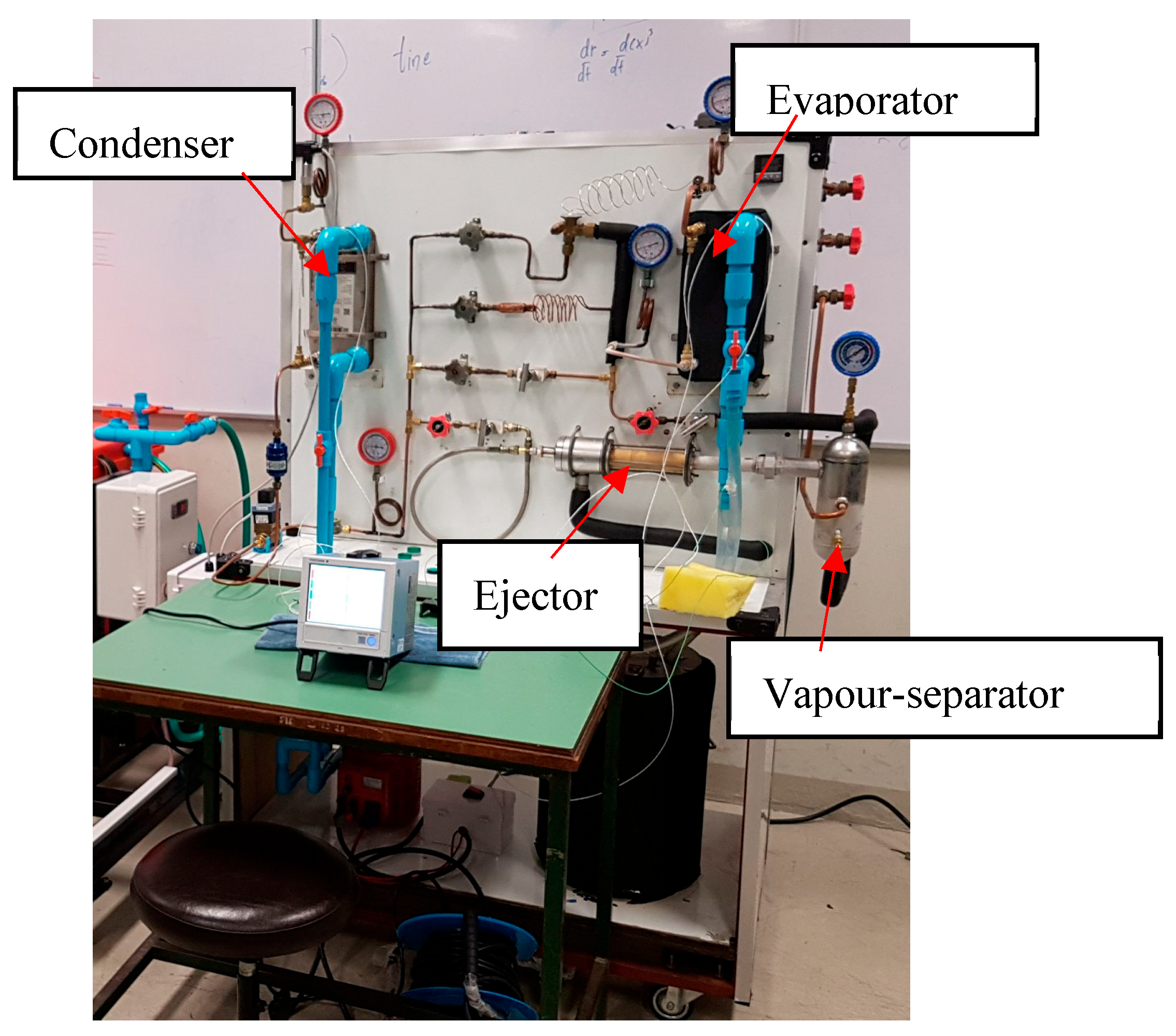
2. Experimental Setup

An experimental heat pump test system that is able to operate with both a vapor-compression heat pump (VCHP) and an ejector–expansion heat pump (EEHP) was built for the investigations. The test system uses R134a as the working fluid in the cycle. The reasons why R134a was used for this experiment are as follows: it was available from the local Thai market at the time of the experiment, and R1234yf was not available at that time. Moreover, R134a is still widely used in many refrigeration or heat pump machines and automobile air-conditioning units, and it has reasonable costs compared to R1234yf, which is very expensive, around four times the cost of R134a. A schematic view and a picture of the heat pump are presented in Figure 2 and Figure 3. The major hardware of the test bench that was used for operating the pump with both the VCHP and the EEHP comprises the compressor, the evaporator, and the condenser. This study demonstrated the improvement potential of the EEHP over the VCHP, wherein the key to the performance improvement is the flow state of the refrigerant.
We used a hermetic reciprocating type of compressor, which is capable of producing a nominal cooling capacity of 2 kW. It is electrically driven by 220VAC with a rated power of 0.75 kw (motor 1 hp). The reasons we selected it are as follows: it has a positive displacement type in which the volume flow rate is a function of the rotational speed; it is widely used for commercial heat pumps, and it is compatible with R134a; and it can withstand relatively high discharge temperatures. A plate heat exchanger (with a heat transfer capacity up to 4.5 kW) is used as the condenser. The hot water is produced at the condenser outlet, and, later, it is stored in a well-insulated tank. The water from the insulated tank is supplied to absorb heat at the condenser via the hot water circulating pump (Samson—1/2 HP). Hence, the superheated vapor at the condenser inlet is condensed at high temperatures and pressures. The hot water temperature is monitored using a thermocouple (type k). The heating capacity (for both the VCHP and the EEHP) can be determined by recording the flow rate of the hot water and the temperature differences at the inlet/outlet condenser. To maintain the hot water temperature at the desired point, the cooling water (produced by another chiller) is pumped through the cooling coil installed within the hot water tank so that it can absorb heat from the hot water. Thus, the hot water temperature can be controlled precisely at the desired point. Hence, the heating rate under steady-state operations can be determined accurately.
The evaporator vessel is also a plate heat exchanger (with a heat transfer capacity of up to 3.5 kW). The chilled water is produced at the evaporator outlet and stored within the well-insulated tank. The immersion heater (with power levels up to 4.0 kW) is placed inside the chilled water tank to control the temperature supplied to the evaporator (this is considered the heat source temperature). The chilled water temperature can be regulated precisely by controlling the heat load produced by the immersion heater by means of a PID controller together with solid-state relay. This chilled water is circulated through the evaporator via a magnetic coupling pump at the desired temperature.

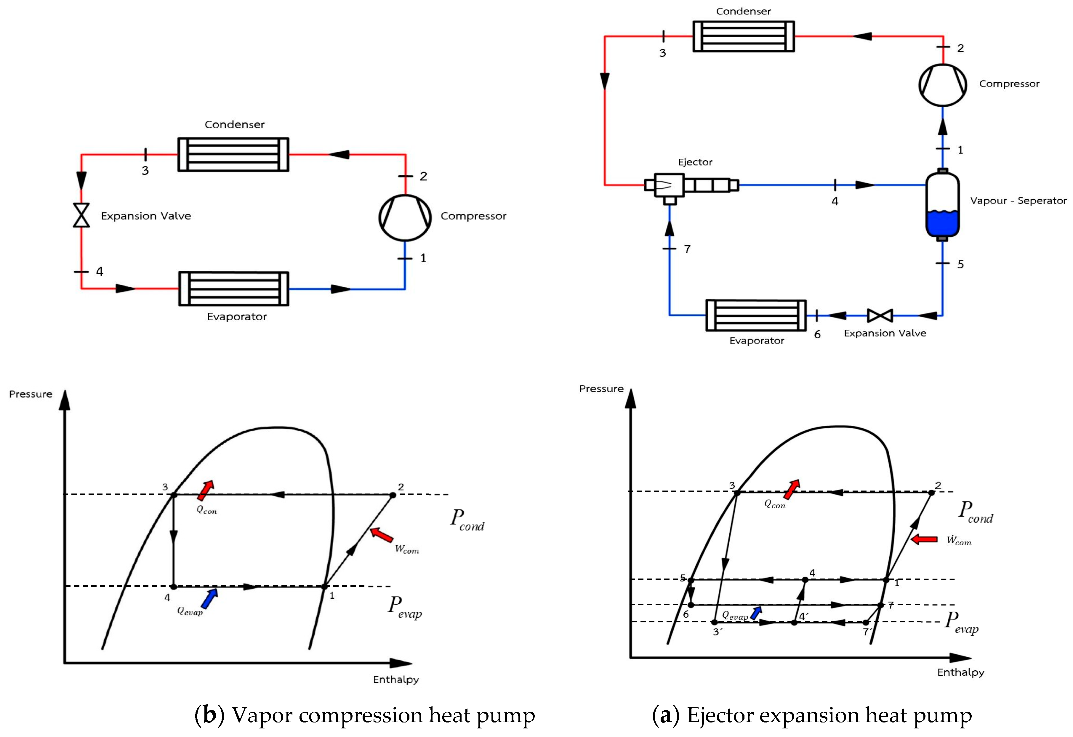
2.1. Test Based on the VCHP

The experimental work based on the VCHP is made possible when valves V1 and V3 are opened while valves V2, V4, V5, and V6 are closed (seen in Figure 2). As a result, when the system is operated, the refrigerant within the evaporator is evaporated, and, hence, heat is absorbed at low temperatures. In this case, the water from the chilled water tank is pumped into the evaporator to apply the cooling load. Consequently, heat absorption at low temperatures (heat source) is made possible. Then, low-temperature vapor at the evaporator outlet is compressed by the compressor to produce the superheated vapor at the compressor discharge. This superheated vapor is condensed within the condenser. In this case, the water is supplied to promote heat rejection. Hence, the hot water can be produced and stored within the hot water tank. After the condensation process is finished, the liquid refrigerant is expanded through the expansion devices to promote a refrigerating effect at the evaporator; thus, the cycle is completed.
During the pre-testing, the system is run continuously to produce the desired hot water temperature. Then, the chilled water (which is produced by another chiller) is circulated through the coil installed within the hot water tank to absorb heat from the hot water. Thus, a constant heat sink temperature is made possible. Additionally, the heating rate can be calculated.

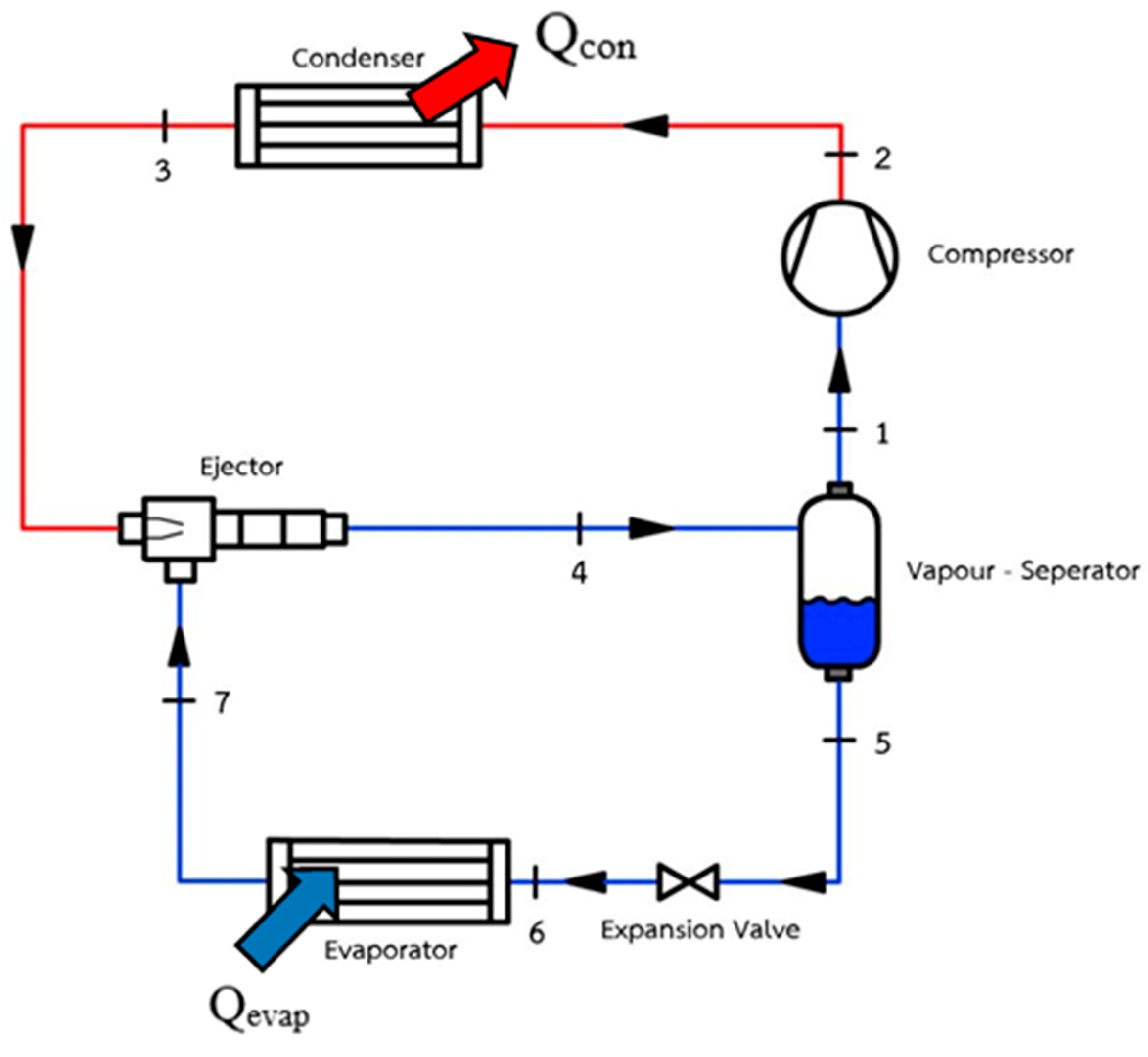
2.2. Test Based on the EEHP

This test can be implemented when closing valves V1 and V3 while opening valves V2, V4, V5, and V6. The liquefied refrigerant at the condenser outlet is accelerated through the primary nozzle of the two-phase ejector, causing a low-pressure region to be produced within the mixing chamber. Thus, the refrigerant within the evaporator, which is connected to the entrainment region of the ejector, is evaporated to produce the low-temperature and low-pressure vapor (i.e., the secondary fluid), which produces refrigerating effects within the evaporator. Due to the fairly large difference in velocity between the primary and secondary fluids, a shear mixing process takes place, which results in momentum transfer from the primary fluid to the secondary fluid. Hence, the secondary fluid is conveyed into the mixing chamber, and its velocity is increased. It is thought that the velocity of the secondary fluid is increased until the choked flow is reached. Hence, the secondary fluid mass flow rate is limited due to the choked flow. Later, the two streams are mixed completely before entering the diffuser. The mixed fluid undergoes the pressure recovery process while moving through the diffuser before entering the vapor separator.
At the vapor separator, the two-phase fluid undergoes phase separation. Hence, the vapor phase (saturated vapor) found at the top of the separator is always sucked up by the compressor. This process is unlike that seen in the VCHP, in which the slightly superheated vapor is compressed by the compressor. This makes a significant difference in the compression process, as we discuss in this paper. After undergoing the compression process, the superheated vapor is condensed within the condenser, and the heating rate is produced by circulating the water through the condenser.
In the present work, the two-phase ejector was designed according to the model proposed by Bilir et al. [31] and Ersoy et al. [32]. Figure 4 shows the drawings of the primary nozzle, mixing chamber, throat, and diffuser used in this work. The suction chamber was fabricated from stainless steel 304 (SUS-304). The mixing chamber and primary nozzle were made of brass. Since the internal geometries of the ejector and the primary nozzle are quite small, the construction material must be brass (which is more easily used for construction and provides highly precise manufacturing). An internal flow profile of the primary nozzle (the converging–diverging type) was obtained using an electrical discharging machine (EDM). As seen in the drawing, an internal flow of the fluid stream occurs under the primary nozzle and the mixing chamber, which are made of brass. Hence, there is no impact on the material used for the experiments.

2.3. Instrumentations and Data Reduction

During the experiments, the heating capacity, electricity consumption, and water flow rate were considered to determine the COPHP of the EEHP and the VCHP. Additionally, the temperature and the pressure at the relevant points are important for determining the COPHP. Hence, the measuring devices and system control must be reliable. In this work, the temperature value was detected using a type-k thermocouple. Meanwhile, the pressure value at the relevant points was detected using a digital pressure transmitter. The temperature and pressure values were recorded using data acquisition, which allows for the monitoring of the real-time operations and steady-state operations. The measuring devices and their uncertainties are shown in Table 1.
For the calibration of the thermocouple, a high-precision mercury thermometer was used. The reference temperature at 0 °C was produced with ice. Meanwhile, the reference at 100 °C was made by boiling water at atmospheric pressure. To calibrate the pressure transducer, the positive pressure was calibrated using a dead-weight tester. The vacuum pressure was calibrated with a double-stage, high-precision mercury barometer. The vacuum was made using a liquid ring vacuum pump. The flow sensor was calibrated with a high-precision rotameter.
During the experiments, the heat pump’s performance was represented by the heating coefficient of performance (COPHP). The heating COP can be calculated when the pressure, temperature, mass flow rate, and electrical energy are measured in experiments. It can be calculated using Equation (1):
C O P H P = Q ˙ H W ˙ c o m p
The heating rate produced at the condenser can be calculated using Equation (2):
Q ˙ H = m ˙ h o t c p T h o t o u t T h o t i n
The electrical energy consumption for the electric motor can be determined by recording the current, voltage, and power factor. Hence, the electrical energy is then determined by Equation (3):
W ˙ p u m p = V I cos ϕ
During experiments, the measuring devices and experimental technique must be reliable in order to obtain accurate results. In this work, the type-k thermocouple probes were calibrated precisely, with uncertainty levels of ±3.0–5.0%. The temperature controller was used to regulate the temperature at the relevant points. It was used with the solid-state relay to control the heater power in order to achieve the desired temperatures of the heat sink and heat source. Furthermore, the pressure transducers were calibrated precisely before they were installed into the test system. The calibration indicated that the uncertainty of the pressure transducers was ±1.0% FS.
The volume flow rates of the hot water flowing through the condenser and the chilled water flowing through the evaporator were observed using a rotameter (1.0% of FS). The temperature and pressure values at the relevant points were indicated and recorded via data acquisition. Therefore, the steady-state operation of the heat pump test system could be precisely monitored.

3. Results and Discussion

3.1. Performance Comparison of an Ejector–Expansion Heat Pump with a Vapor-Compression Heat Pump

The performance of the EEHP compared with the VCHP under various working conditions is presented and discussed. The aim of this section is to explain how the EEHP provides an advantage over the VCHP. The two systems were tested under the same heat sink and heat source so that a fair comparison between the two systems was achieved. A heat sink temperature (TH) of between 45 and 60 °C was studied, while the temperature of the heat source (TL) ranged from 8 to 16 °C. The heat rate at the condenser of the two systems was observed for discussion. The refrigerant’s pressure and temperature were also recorded so that insights into the expansion work recovery of the two-phase ejector could be provided and explained clearly. The reason why the EEHP provides an advantage over the VCHP is then proposed. There are not currently many works that prove this; hence, the results presented in this section constitute new information within this research field.

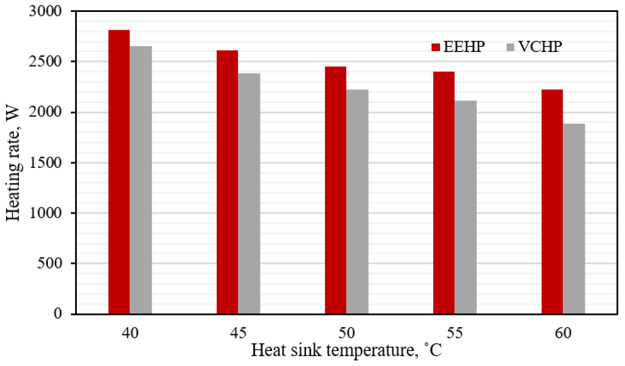
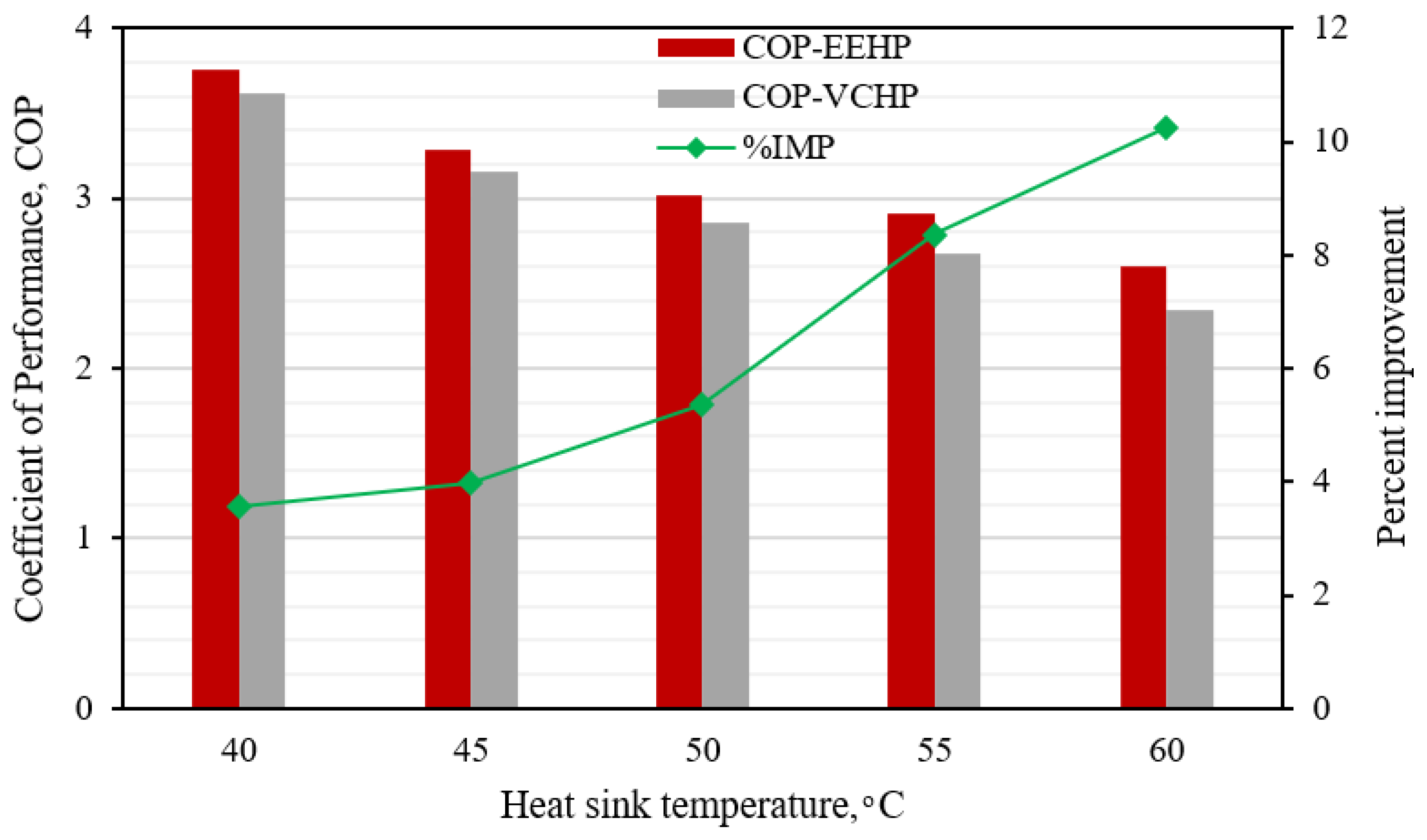
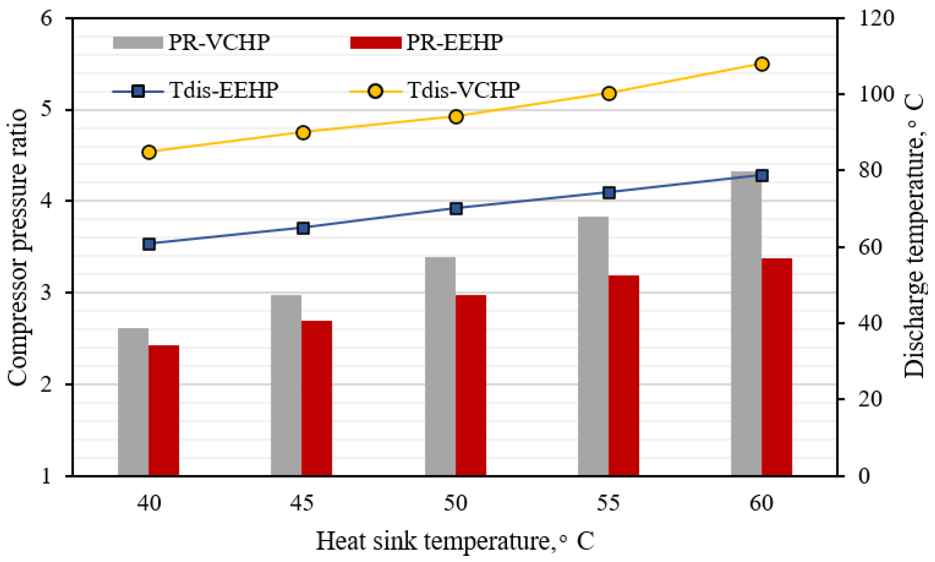
3.1.1. The Impact of Variations in the Heat Sink Temperature

Here, the EEHP and VCHP were tested under a fixed heat source at 8 °C, while the heat sink was increased from 40 to 60 °C. The electricity consumption and heating capacity were recorded for discussion. The results of the two systems are shown in Figure 5.
Figure 5 shows that the heating rate produced by the two systems decreases when the heat sink temperature increases. This is because there is a larger difference in temperature between the heat sink and the heat source. A larger difference in temperature causes a lower cooling load to be absorbed at the evaporators of the two systems because a higher refrigerant quality (x) at the evaporator inlet is produced. This mitigates the system’s ability to absorb heat at low temperatures (at the evaporator). However, it is clear that the EEHP produces a higher heating rate than the VCHP. This is due to the fact that the throttling loss of the whole cycle is mitigated by the two-phase ejector. In such a case, a two-phase ejector can increase the specific enthalpy difference under a heat absorption process at low temperatures (increasing the specific cooling load). In addition, the compression pressure ratio of the compressor can also be reduced by a two-phase ejector, whereby the specific work for the compressor is reduced. This is because of the pressure-lifting effect of the two-phase ejector. To clarify this finding, we present the processes of the two systems in the P–h diagram shown in Figure 6.
From Figure 6, it is obvious that, for the EEHP, the refrigerant entering the evaporator is in state 6 (shown in Figure 6b) while that for the VCHP is in state 4 (shown in Figure 6a). Moreover, the refrigerant quality of the EEHP is lower than that of the VCHP (closer to the saturated liquid state), as supported by Sutthivirode et al. [28] and Bilir et al. [31]. Hence, the refrigerant quality is around 0.05–1.0. This is because the pressure ratio across the expansion valve is relatively low, resulting in a slight phase change in the refrigerant across the expansion device. This causes the specific enthalpy of the refrigerant via the EEHP to be lower. For the VCHP, the liquefied refrigerant pressure is decreased from high-side to low-side pressure (state 3 to 4) via the expansion devices (undergoing the expansion process). As a result, at the evaporator inlet, the refrigerant quality of the VCHP is higher than that of the EEHP. The refrigerant quality, based on the VCHP, is around 0.25–0.35, depending on the working conditions. This results in a higher specific enthalpy before entering the evaporator. Thus, the EEHP can absorb more of the specific cooling load as the refrigerant flows through the evaporator. This results in a higher level of heat rejection at the condenser via the EEHP. Additionally, a higher compressor suction pressure is achieved by the EEHP because of its ability to induce a pressure lift effect when using the two-phase ejector. This results in a lower compression ratio of the compressor, generating lower compressor-specific work (work per unit mass). Furthermore, the refrigerant temperature at the compressor’s discharge of the EEHP is much lower than that of the VCHP. This is the result of az lower compressor pressure ratio and the state of the refrigerant during the compressor suction, i.e., a saturated vapor under the separator pressure. This is unlike the case of the VCHP, in which the compressor pressure ratio is higher while the refrigerant state is a superheated vapor at the evaporating pressure. Therefore, the working characteristics of the heat pump can be improved by means of the two-phase ejector, as is indicated by the improvement of the heating COP.
The heating COP (COPHP) is the ratio of the heat rejection at the condenser (useful heat for the heat pump’s operation) to the electricity consumption. The measured electricity consumption of the two systems under the same working heat sink/heat source is shown in Figure 7, while the system COP is shown in Figure 8.
Figure 7 clearly shows that the electricity consumption of the two systems increases when the heat sink temperature increases. This is because the condenser pressure is increased while the compressor suction pressure is kept constant; this causes a higher compressor compression ratio, resulting in higher electricity consumption. Figure 7 also shows that, for a certain heat sink temperature, the EEHP requires higher levels of electricity than the VCHP. This is because a larger amount of the mass flow rate is compressed by the compressor, as seen in Figure 7 (please see column). However, a useful heating rate is produced by the EEHP under the same heat sink temperature. Hence, the system COP of the EEHP is still higher than that of the VCHP throughout the heat sink temperature range of 40–60 °C, as shown in Figure 8. Figure 8 also shows that the improvement potential of COPHP via the EEHP is 3.7–11.2%.
For the EEHP, the higher mass flow rate is caused by the compressor suction pressure being higher than that of the VCHP. Herein, at the compressor suction port, a higher refrigerant density is produced by the EEHP. Since the compressor used is a reciprocating type (a type of positive displacement machine), the same volume flow rate at a fixed rotational speed is achieved. Therefore, a higher mass flow rate is achieved at a fixed compressor speed because the refrigerant density at the suction port of the EEHP is higher than that in the VCHP. In this case, a higher refrigerant density is produced by the EEHP because the compressor suction port is connected to the vapor separator; hence, the saturated vapor refrigerant under intermediate pressure is always drawn into the compressor suction port, as indicated by Sutthivirode et al. [28] and Bilir et al. [31]. As for the VCHP operation, the compressor suction port is connected to the evaporator outlet, in which a low degree of superheated vapor under the low-side pressure is produced. Thus, a difference is always found in the refrigerant density at the compressor suction ports of the two systems, even when the evaporating temperature is similar. In this case, the compressor suction pressure and refrigerant temperature are used to determine the refrigerant density of the two systems against the heat sink temperature. The determined refrigerant density and suction pressure are depicted in Figure 9.
Another advantage of operating with a higher mass flow rate for the EEHP is that a higher heat rejection rate is made possible at the condenser, which yields a higher heating rate for the heat pump. This is why the heating capacity produced by the EEHP is higher than that produced by the VCHP throughout the range of the heat sink temperatures.
As explained earlier, the compressor suction pressure (Psuc-comp) of the EEHP is higher than that that of the VCHP at various heat sink temperatures. Therefore, the EEHP always produces a lower compressor pressure ratio (PRcomp) under the same heat sink temperature. Therefore, the compressor discharge temperature (Tdis-comp) of the EEHP is always lower than that of the VCHP. The results of testing this phenomenon are shown in Figure 10.
From Figure 10, it is obvious that the Tdis-comp of the EEHP is much lower than that of the VCHP. This indicates another advantage of using a two-phase ejector in the heat pump: better lubrication of the mechanical compressor. It is well known that a higher refrigerant discharge temperature results in poorer lubrication due to the lubricant having low viscosity, and it also mitigates its ability to mix with the refrigerant for lubrication. Hence, the heat pump system working with the two-phase ejector is beneficial to the lifespan of the compressor and also to the overall system performance.
As discussed in this section, the benefit of using the two-phase ejector in the heat pump for expansion work recovery (EEHP) is clear. A clarification of how the EEHP presents advantages over the VCHP is presented under various heat sink conditions. The EEHP always exhibits better performance throughout the range of the specified heat sink. However, experimental proof is still required for when the low-temperature heat source is varied. This is presented later.

3.1.2. Impact of Variations in the Heat Source Temperature

The performance of the EEHP under various heat source temperatures (TL) is discussed in this section in order to assess the experimental performance of the two heat pump systems for a wider range of heat source temperatures. The results can later be used as a reference case for further developing a larger-scale EEHP that still exhibits an optimum performance. This is beneficial for the selected heat sources for operating heat pumps, such as air sources, water sources, geothermal sources, etc.
During the experiment, the heat sink temperature of the EEHP was kept constant at 50 °C, which means that the hot water was also produced at 50 °C. The heat source temperature varied, ranging from 8 to 16 °C. This is so that the performance of the EEHP could be demonstrated based on a fairly high pressure ratio. The heating capacity, electricity consumption, and COP were observed for assessment.
Figure 11 shows the heating capacity against the heat source temperatures. The heating rate increases with the heat source temperature. At a higher heat source temperature (TL), there is a decrease in the expansion pressure ratio. This causes a higher heat load to be absorbed in the evaporator. As a result, more refrigerant vapor is produced at the evaporator’s outlet (higher secondary mass flow rate). In addition, the working pressure and temperature of the vapor separator are increased. This causes a higher refrigerant density to be produced, and it is later compressed by the compressor. Therefore, a higher mass flow rate under a fixed volume flow rate is found in the compressor and condenser. The heating capacity is increased when the heat source temperature is increased.
Since the refrigerant mass flow rate is increased with the heat source temperature, the compressor requires higher levels of electrical energy for its operations. Figure 12 shows the increasing trend of electricity consumption. It is evident that there is a slight increase in the electricity consumption when increasing the TL. This is because of the ability to reduce the specific work of the two-phase ejector, which yields a lower compressor discharge temperature, as previously discussed in Section 3.1. The trade-off between electricity consumption and heating capacity is demonstrated by the COPHP of the EEHP, as depicted in Figure 13.
Figure 13 reveals that the COPHP of the two systems increases when the heat source temperature (TL) increases. More interestingly still, the percentage improvement of the EEHP compared with that of the VCHP is around 6.1–11.6%. This is because the EEHP can produce a higher heating capacity, as shown in Figure 13. This finding is identical to the result of decreasing the TH while the TL is kept constant, as discussed in Section 3.1. This implies that the COPHP of the EEHP is significantly dependent on the pressure ratio between the heat sink and the heat source. This is linked to the two-phase ejector operation, as indicated by the entrainment ratio (ER) and the pressure lift ratio. Hence, studies of the two-phase ejector’s performance should also focus on how the pressure ratio of the primary fluid to the secondary fluid (or expansion pressure) affects the ER and the pressure recovery (pressure lift), as proposed by many researchers [28,29,30,31,32]. Thus, this present work provides a reference case for developing a more accurate model for designing a two-phase ejector.

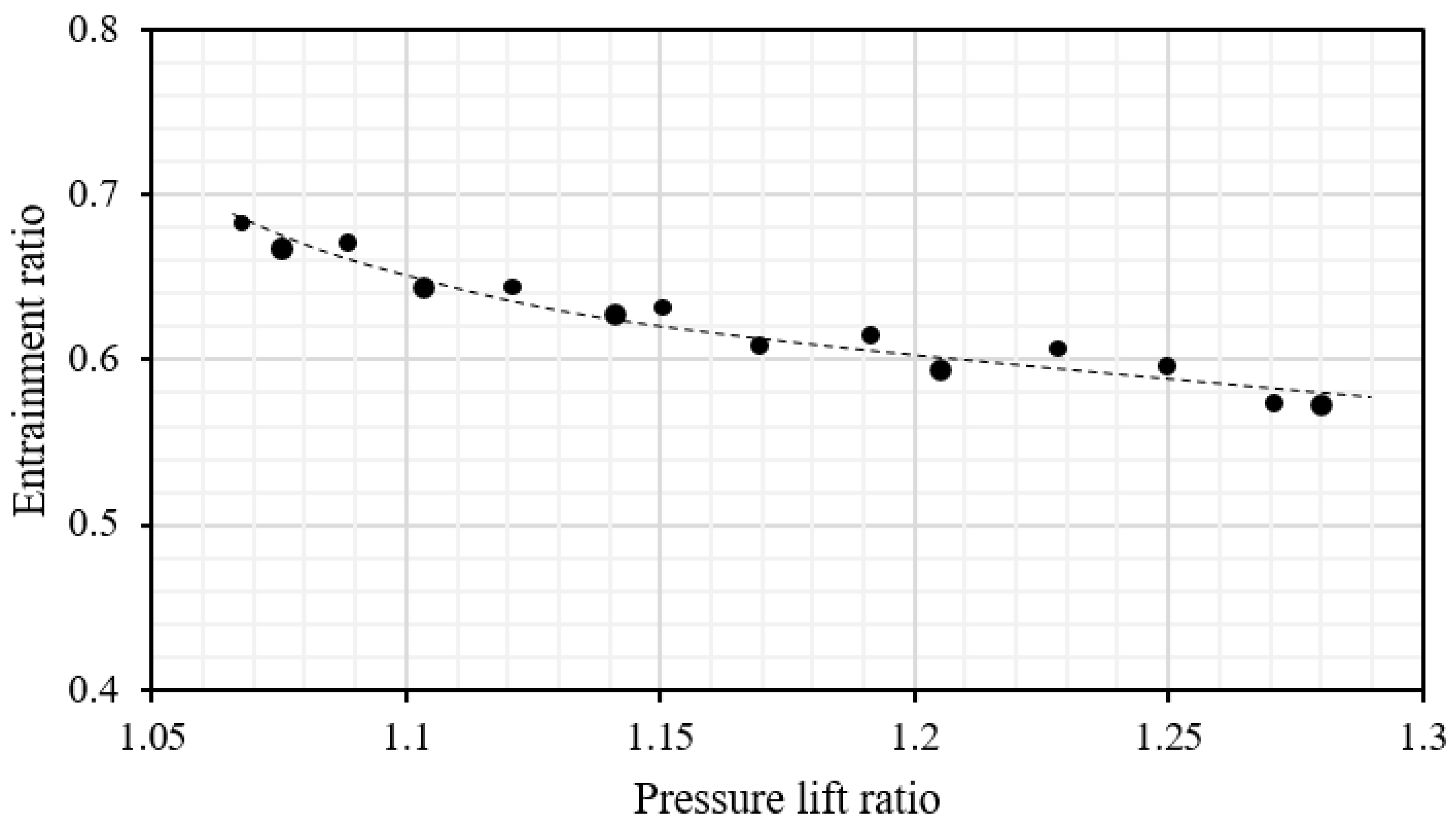
3.2. Impact of the Expansion Pressure Ratio on the Two-Phase Ejector’s Performance

The performance of the two-phase ejector used in the EEHP is discussed based on the dimensionless parameters. This is so that the results can be further used for scaling up the heat pump to produce a higher heating rate. Since the experimental results on this topic are still lacking, the results based on the dimensionless parameter are useful as a base reference design or as reference data for developing a more accurate design model.
In this section, the pressure ratio of the condenser to the evaporator pressure, as represented by Equation (4) (considered as the PRexpan), is used to represent the flow process of the primary nozzle (the expansion process). This parameter is key to producing a high-speed two-phase stream after the two-phase refrigerant leaves the primary nozzle’s exit:
P R e x p a n = P c o n d P e v a p
Additionally, the pressure lift ratio is introduced to represent the pressure recovery process, which is defined by Equation (5):
P R l i f t = P e j d i s P e v a p
The two-phase ejector’s performance is represented by the mass entrainment ratio (ER) which is shown in Equation (6). This ER is presented against the PRexpan and the PRlift to demonstrate the overall two-phase ejector’s performance as a reference case:
E R = m ˙ sec m ˙ p r i
Figure 14 shows the variations in the pressure lift ratio against the expansion pressure ratio. It is evident that a larger expansion pressure ratio provides a higher pressure lift. This means that a larger differential pressure between the heat sink (Pcond) and the heat source (Pevap) causes a higher ejector discharge pressure, as indicated by a higher pressure lift ratio. The higher ejector discharge pressure benefits the compressor operations (lower compressor pressure ratio). A better compression process is achieved, which is indicated by a lower compressor discharge temperature and a lower specific work level, as discussed in Section 3.1. However, a higher expansion pressure ratio affects the entrainment performance, as is shown in Figure 15.
Figure 15 reveals that a reduction in the mass entrainment ratio is found when the expansion pressure is larger. In this case, the two-phase stream produces higher quality at the nozzle exit, which implies that the two-phase fluid has more vapor mixture. Since the vapor requires a larger flow area within the mixing chamber, the secondary fluid flow area is reduced. As a result, the ER decreases when the expansion pressure ratio is increased. A lower entrainment ratio yields a lower cooling load. This mitigates the capability to produce the heating rate of the EEHP. It is clear that there is a trade-off between the pressure lift ratio and the entrainment ratio for a certain expansion pressure ratio, as shown in Figure 13 and Figure 14. Therefore, the heating capacity of the EEHP must be designed based on these parameters, which reflect the actual working conditions. It is evident that the two-phase ejector’s performance plays a crucial role in the overall system performance of the EEHP because it is key to the recovery expansion work. However, to validate the theoretical design of the two-phase ejector in a more convenient manner, the mass entrainment ratio was plotted against the pressure lift ratio, which is shown in Figure 16. This is for the simplicity of further validation with the theoretical results calculated using the 1D model, as proposed by many researchers [26,27,28,29,30,31,32].
A decrease in the entrainment ratio is found when the pressure lift ratio is increased. This demonstrates that the ability to achieve the mass entrainment performance of the two-phase ejector is dependent on its working condition, which is associated with the heat sink and heat source conditions. Hence, it is not possible to achieve a higher mass entrainment ratio while the pressure lift ratio is relatively high. According to published works [31,32], the two-phase ejector’s performance, as determined theoretically, is based on the performance curve shown in Figure 16. Hence, the results shown in Figure 16 can be used at a later date to develop a more accurate design model for a two-phase ejector.

4. Conclusions

An experimental investigation into the heat pump performance of a VCHP and an EEHP was undertaken. The comparative performance of the two heat pump systems was assessed to demonstrate the potential for improvement of the EEHP over the VCHP. This study showed that the two-phase ejector that is used in the EEHP is able to reduce the expansion loss of the heat pump system. The significant findings of the present work can be summarized as follows:
  • The EEHP can produce higher QH and COPHP values than the VCHP under a heat sink (TH) between 40 and 60 °C. The percentage improvement is 3.7–11.2% compared to the VCHP (conventional system). A higher percentage improvement is achieved by increasing the TH;
  • As the heat source (TL) is increased while the heat sink (TH) is kept constant, the EEHP achieves a higher heating rate and COPHP than the VCHP. The percentage improvement is 6.1–11.6%. A lower heat source temperature yields a higher percentage improvement;
  • The key to improving performance is the use of a two-phase ejector. This is because of the pressure lift effect and the mass entrainment performance. Additionally, an increase in the compressor suction pressure via the pressure lift causes the refrigerant density to be increased, which results in a higher mass flow rate (at a fixed compressor rotational speed) through the compressor and condenser. Hence, the EEHP yields a higher heating rate than the VCHP;
  • The expansion pressure ratio (the pressure ratio between the heat sink and the heat source) significantly affects the two-phase ejector operations, as indicated by the entrainment performance and the pressure lift ratio;
  • There is a trade-off between the pressure lift ratio and the entrainment ratio for a certain expansion pressure ratio. The heating capacity of the EEHP is associated with these parameters, which demonstrate the actual working conditions.
The proposed results will benefit the further development of heat pumps in which the system performance and the system COPHP are improved. In addition, the results based on the dimensionless parameters can be used as a reference case for developing a more accurate design model. This is because it is difficult to precisely predict the fluid properties of a high-speed two-phase flow, which is a major factor in predicting an EEHP’s performance.

Author Contributions

Conceptualization, W.S., K.O. and T.T.; methodology, W.S., K.O. and T.T.; formal analysis, W.S., K.O. and T.T.; investigation, W.S., K.O. and T.T.; data curation, W.S., K.O. and T.T.; writing—original draft preparation, W.S., K.O. and T.T.; writing—review and editing, W.S., K.O. and T.T. All authors have read and agreed to the published version of the manuscript.

Funding

This research was funded by King Mongkut’s University of Technology, North Bangkok. Contract no.: KMUTNB-65-KNOW-24.

Data Availability Statement

Not applicable.

Acknowledgments

The authors would like to thank Satha Aphornratana at the Siridhorn International Institute of Technology, Thammasat University, for offering valuable comments.

Conflicts of Interest

The authors declare no conflict of interest.

Nomenclature

ACross-sectional area (m2)
COPCoefficient of performance
EEHPEjector–expansion heat pump
EREntrainment ratio
ElecElectricity consumption
hRefrigerant-specific enthalpy (kJ kg−1)
VCHPVapor-compression heat pump
mMass flow rate (kg s−1)
PPressure (bar)
PRPressure ratio
QHeat transfer rate (kW)
TTemperature (°C)
Subscripts       
chillRepresents chilled water
conRepresents the condenser
dis-compRepresents the compressor discharge
evapRepresents the evaporator
evap-outRepresents the evaporator outlet
exit-nozzCondition at the primary nozzle’s exit
expanRepresents the expansion process
HRefers to the heat sink
hotRefers to hot water
in-nozzInlet nozzle condition
LRefers to the heat source
liftLift ratio
mixCondition at ejector mixing
suc-compCondition at compressor suction
priRepresents the primary fluid
secRepresents the secondary fluid
t-ejEjector mixing chamber throat
t-nozzPrimary nozzle throat

References

  1. Huang, Z.; Li, T. Experimental Investigation of Gravity Effect on a Vapor Compression Heat Pump System. Energies 2023, 16, 4412. [Google Scholar] [CrossRef]
  2. Szymiczek, J.; Szczotka, K.; Banaś, M.; Jura, P. Efficiency of a Compressor Heat Pump System in Different Cycle Designs: A Simulation Study for Low-Enthalpy Geothermal Resources. Energies 2022, 15, 5546. [Google Scholar] [CrossRef]
  3. Zhou, Y.; Peng, B.; Zhu, B. Assessment of Optimal Operating Range and Case Verification of a Waste Heat Air-Source Heat Pump Water Heater Based on a Semiempirical Parametric Model. Energies 2023, 16, 2289. [Google Scholar] [CrossRef]
  4. Navarro-Esbrí, J.; Mota-Babiloni, A. Experimental analysis of a high temperature heat pump prototype with low global warming potential refrigerant R-1336mzz (Z) for heating production above 155 °C. Int. J. Thermofluids 2023, 17, 100304. [Google Scholar] [CrossRef]
  5. Trancossi, M.; Cannistraro, G.; Pascoa, J. Thermoelectric and solar heat pump use toward self sufficient buildings: The case of a container house. Therm. Sci. Eng. Prog. 2020, 18, 100509. [Google Scholar] [CrossRef]
  6. Zanetti, E.; Azzolin, M.; Bortolin, S.; Busato, G.; Del Col, D. Experimental data and modelling of a dual source reversible heat pump equipped with a minichannels evaporator. Therm. Sci. Eng. Prog. 2022, 35, 101471. [Google Scholar] [CrossRef]
  7. Shiravi, A.H.; Ghanbarpour, M.; Palm, B. Experimental evaluation of the effect of mechanical subcooling on a hydrocarbon heat pump system. Energy 2023, 274, 127406. [Google Scholar] [CrossRef]
  8. Zhang, Q.; Huang, H.; Zhai, H.; Zhao, W.; Lü, X. Experimental research on direct expansion heat pump flue gas waste heat recovery and humidification nitrogen reduction system. J. Clean. Prod. 2023, 406, 137000. [Google Scholar] [CrossRef]
  9. Hu, Z.; Li, Y.; El-Mesery, H.S.; Yin, D.; Qin, H.; Ge, F. Design of new heat pump dryer system: A case study in drying characteristics of kelp knots. Case Stud. Therm. Eng. 2022, 32, 101912. [Google Scholar] [CrossRef]
  10. Yuan, Y.; Hassan, A.; Zhou, J.; Zeng, C.; Yu, M.; Emmanuel, B. Experimental and numerical investigation on a solar direct-expansion heat pump system employing PV/T & solar thermal collector as evaporator. Energy 2022, 254, 124312. [Google Scholar]
  11. Wang, Y.; Zong, S.; Song, Y.; Cao, F.; He, Y.; Gao, Q. Experimental and techno-economic analysis of transcritical CO2 heat pump water heater with fin-and-tube and microchannel heat exchanger. Appl. Therm. Eng. 2021, 199, 117606. [Google Scholar] [CrossRef]
  12. Chiriboga, G.; Capelo, S.; Bunces, G.C.; Cepeda, J.; Gordillo, G.; Montesdeoca, D.E. Harnessing of geothermal energy for a greenhouse in Ecuador employing a heat pump: Design, construction, and feasibility assessment. Heliyon 2021, 7, e08608. [Google Scholar] [CrossRef]
  13. Lim, H.; Kim, C.; Cho, Y.; Kim, M. Energy saving potentials from the application of heat pipes on geothermal heat pump system. Appl. Therm. Eng. 2017, 126, 1191–1198. [Google Scholar] [CrossRef]
  14. Ye, J.; Ni, L. Experimental study on heating performance of air source heat pump fresh air unit with fresh air and return air mixing in severe cold regions. Energy Build. 2023, 283, 112839. [Google Scholar] [CrossRef]
  15. Leonzio, G.; Fennell, S.; Shah, N. Air-source heat pumps for water heating at a high temperature: State of the art. Sustain. Energy Technol. Assess. 2022, 54, 102866. [Google Scholar] [CrossRef]
  16. Wu, J.; Sun, S.; Song, Q.; Wang, D.; Sun, D. Subcritical recuperative air-to-water heat pump with zeotropic mixtures: Comparative and performance assessment. Energy Rep. 2022, 8, 13682–13697. [Google Scholar] [CrossRef]
  17. Huang, M.J.; Hewitt, N.J. The experimental analysis of the effect of ambient factors on the defrosting of economised vapour injection compressor air source heat pump in marine climates. Int. J. Refrig. 2013, 36, 820–827. [Google Scholar] [CrossRef]
  18. Li, K.; Ma, J.; Zhang, B.; Su, L.; Liu, N.; Zhang, H.; Dou, B.; He, Q.; Zhou, X.; Tu, R. Experimental study on low temperature heating performance of different vapor injection heat pump systems equipped with a flash tank and economizers for electric vehicle. Appl. Therm. Eng. 2023, 227, 120428. [Google Scholar] [CrossRef]
  19. Yang, T.; Zou, H.; Tang, M.; Tian, C.; Yan, Y. Experimental performance of a vapor-injection CO2 heat pump system for electric vehicles in −30 °C to 50 °C range. Appl. Therm. Eng. 2022, 217, 119149. [Google Scholar] [CrossRef]
  20. Li, J.; Fan, Y.; Zhao, X.; Bai, X.; Zhou, J.; Badiei, A.; Myers, S.; Ma, X. Design and analysis of a novel dual source vapor injection heat pump using exhaust and ambient air. Energy Built Environ. 2022, 3, 95–104. [Google Scholar] [CrossRef]
  21. Boccardi, G.; Botticella, F.; Lillo, G.; Mastrullo, R.; Mauro, A.W.; Trinchieri, R. Experimental investigation on the performance of a transcritical CO2 heat pump with multi-ejector expansion system. Int. J. Refrig. 2017, 82, 389–400. [Google Scholar] [CrossRef]
  22. Ghazizade-Ahsaee, H.; Askari, I.B. The application of thermoelectric and ejector in a CO2 direct-expansion ground source heat pump; energy and exergy analysis. Energy Convers. Manag. 2020, 226, 113526. [Google Scholar] [CrossRef]
  23. Zhu, Y.; Huang, Y.; Li, C.; Zhang, F.; Jiang, X. Experimental investigation on the performance of transcritical CO2 ejector–expansion heat pump water heater system. Energy Convers. Manag. 2018, 167, 147–155. [Google Scholar] [CrossRef]
  24. Zhang, Z.; Feng, X.; Tian, D.; Yang, J.; Chang, L. Progress in ejector-expansion vapor compression refrigeration and heat pump systems. Energy Convers. Manag. 2020, 207, 112529. [Google Scholar] [CrossRef]
  25. Li, S.; Lu, J.; Li, W.; Huang, S.; Tian, L. Comparative performance of ternary azeotropic mixtures as substitutes for R134a in dual-temperature air source heat pump combined ejector. Therm. Sci. Eng. Prog. 2023, 37, 101577. [Google Scholar] [CrossRef]
  26. Fan, C.; Yan, G.; Yu, J. Thermodynamic analysis of a modified solar assisted ejector-compression heat pump cycle with zeotropic mixture R290/R600a. Appl. Therm. Eng. 2019, 150, 42–49. [Google Scholar] [CrossRef]
  27. Al-Sayyab, A.K.S.; Navarro-Esbrí, J.; Mota-Babiloni, A. Energy, exergy, and environmental (3E) analysis of a compound ejector-heat pump with low GWP refrigerants for simultaneous data center cooling and district heating. Int. J. Refrig. 2022, 133, 61–72. [Google Scholar] [CrossRef]
  28. Sutthivirode, K.; Thongtip, T. Experimental investigation of a two-phase ejector installed into the refrigeration system for performance enhancement. Energy Rep. 2022, 8, 7263–7273. [Google Scholar] [CrossRef]
  29. Zhang, Y.; Wei, X.; Qin, X. Experimental study on energy, exergy, and exergoeconomic analyses of a novel compression/ejector transcritical CO2 heat pump system with dual heat sources. Energy Convers. Manag. 2022, 271, 116343. [Google Scholar] [CrossRef]
  30. Nemati, A.; Nami, H.; Yari, M. A comparison of refrigerants in a two-stage ejector-expansion transcritical refrigeration cycle based on exergoeconomic and environmental analysis. Int. J. Refrig. 2017, 84, 139–150. [Google Scholar] [CrossRef]
  31. Bilir, N.; Ersoy, H.K. Performance improvement of the vapour compression refrigeration cycle by a two-phase constant area ejector. Int. J. Energy Res. 2009, 33, 469–480. [Google Scholar] [CrossRef]
  32. Ersoy, H.K.; Bilir, N. The influence of ejector component efficiencies on performance of ejector expander refrigeration cycle and exergy analysis. Int. J. Exergy 2010, 7, 425–438. [Google Scholar] [CrossRef]
Figure 1. A cycle description for the ejector–expansion heat pump (EEHP).
Energies 16 05889 g001
Figure 2. A schematic diagram of the heat pump test system.
Energies 16 05889 g002
Figure 3. A picture of the heat pump test system.
Energies 16 05889 g003
Figure 4. The two-phase ejector and the primary nozzle.
Energies 16 05889 g004
Figure 5. The heating rate against the heat sink temperature of the EEHP and VCHP.
Energies 16 05889 g005
Figure 6. P–h diagrams of the EEHP and VCHP processes.
Energies 16 05889 g006
Figure 7. The electricity consumption and mass flow rate versus the heat sink temperatures.
Energies 16 05889 g007
Figure 8. The heat pump COP and percentage improvement against the heat sink temperature.
Energies 16 05889 g008
Figure 9. The compressor suction pressure and refrigerant density of the EEHP and VCHP.
Energies 16 05889 g009
Figure 10. The refrigerant discharge temperature and the compressor pressure ratio.
Energies 16 05889 g010
Figure 11. The heating capacity against the heat source temperature.
Energies 16 05889 g011
Figure 12. The electricity consumption against the heat source temperature.
Energies 16 05889 g012
Figure 13. COP and percentage improvement against the heat source temperature.
Energies 16 05889 g013
Figure 14. The pressure lift ratio with variations in the expansion ratio.
Energies 16 05889 g014
Figure 15. The entrainment ratio when varying the expansion pressure ratio.
Energies 16 05889 g015
Figure 16. The pressure lift ratio against the entrainment ratio.
Energies 16 05889 g016
Table 1. The measuring devices.
ItemUncertaintyModel
Data acquisition±0.15%Yokogawa GP10-1-E-F/UC20
Power meter±0.2%Hioki PQ3100
Thermocouple3.0–5.0%Type K
Pressure transducer1.0%FSDixell, PF11
Volume flow meter3.5–5.0%Burkert, 8030SE30
Disclaimer/Publisher’s Note: The statements, opinions and data contained in all publications are solely those of the individual author(s) and contributor(s) and not of MDPI and/or the editor(s). MDPI and/or the editor(s) disclaim responsibility for any injury to people or property resulting from any ideas, methods, instructions or products referred to in the content.

