Research and Development of the Oxy-Fuel Combustion Power Cycle for the Combined Production of Electricity and Hydrogen
Abstract
:1. Introduction
1.1. The Relevance of the Decarbonization of Electricity and Hydrogen Production
1.2. Reducing Carbon Dioxide Emissions from the Steam Methane Reforming Plants
1.3. Oxy-Fuel Combustion Technology for the Combined Production of Electricity and Hydrogen
2. Research and Development of the Steam Methane Reforming Plant with Oxy-Fuel Combustion
2.1. Existing and Promising Technological Schemes in the Steam Methane Reforming Plants
2.2. Mathematical Models of the Steam Methane Reforming Plants
- Stoichiometric fuel combustion;
- Zero pressure loss in pipelines;
- No nitrogen oxides formed during combustion;
- Energy losses during mixing of methane and steam were not considered.
2.3. Thermodynamic Analysis of the Steam Methane Reforming Plants
3. Research and Development of a Novel Oxy-Fuel Combustion Power Cycle for Electricity and Hydrogen Production
3.1. Technological Scheme of the Prospective Oxy-Fuel Combustion Power Cycle
3.2. Mathematical Model of the Prospective Oxy-Fuel Combustion Power Cycle
3.3. Thermodynamic Analysis the Prospective Oxy-Fuel Combustion Power Cycle
4. Conclusions
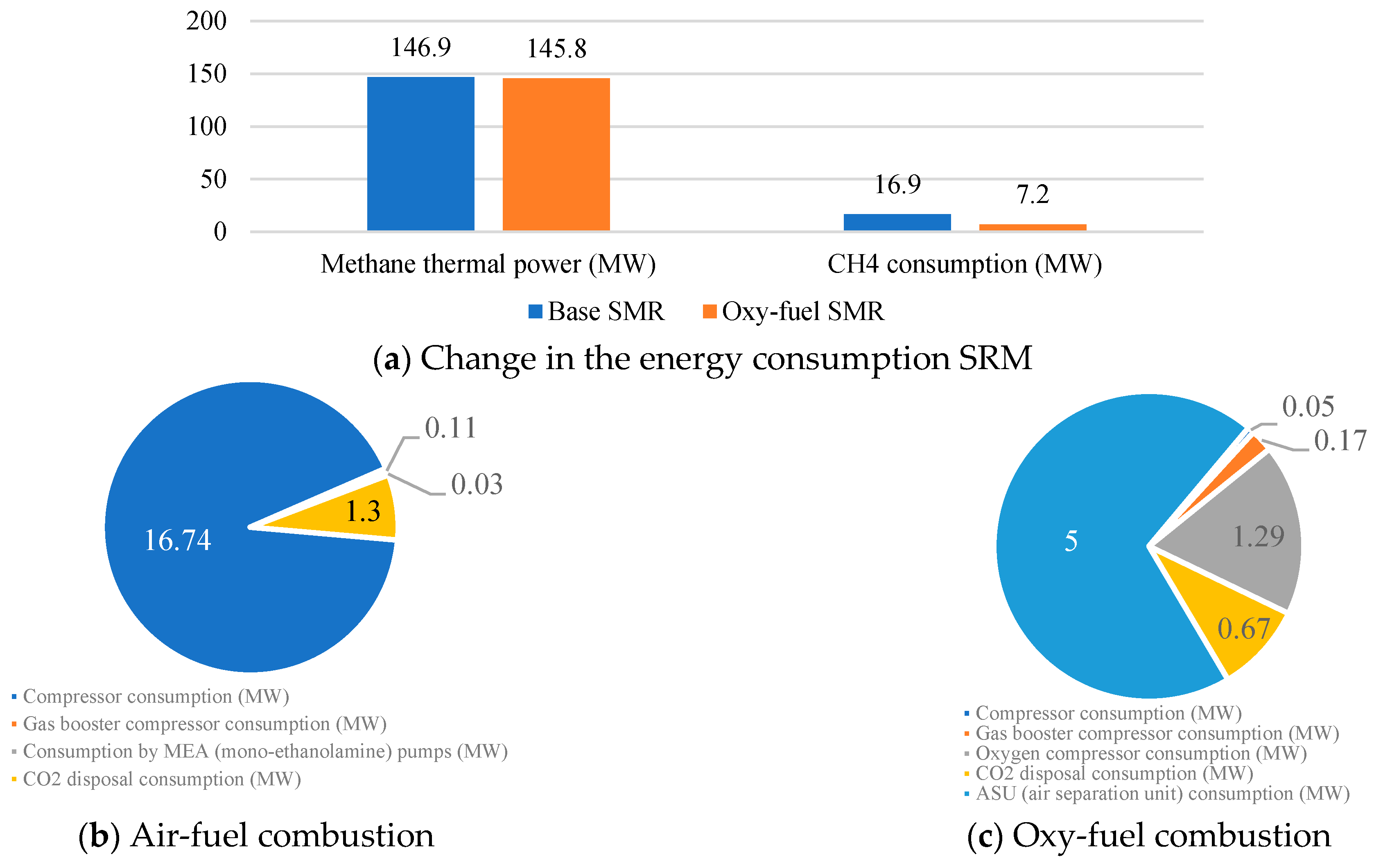
- In the course of the research, the SMR process with oxy-fuel combustion was found to have a fuel HUF 8.1% higher than in the SMR process with absorption purification of exhaust gases. It also offers the reduction of auxiliary power consumption and CO2 emissions by 2.3 and 22, respectively. However, the use of pure oxygen and CO2 at an elevated temperature necessitates the supply of 1.6 times more CH4 to maintain the temperature in the reformer.
- The configuration of the hydrogen production process that is based on steam methane reforming with oxy-fuel combustion is a more efficient and environmentally safe solution compared to traditional processes. The SMR process with oxygen fuel combustion achieves a 22-fold reduction in CO2 emissions per 1 kg of H2 produced. However, the need for a continuous supply of pure oxygen raises a number of issues and requires a detailed economic analysis to be conducted in further research.
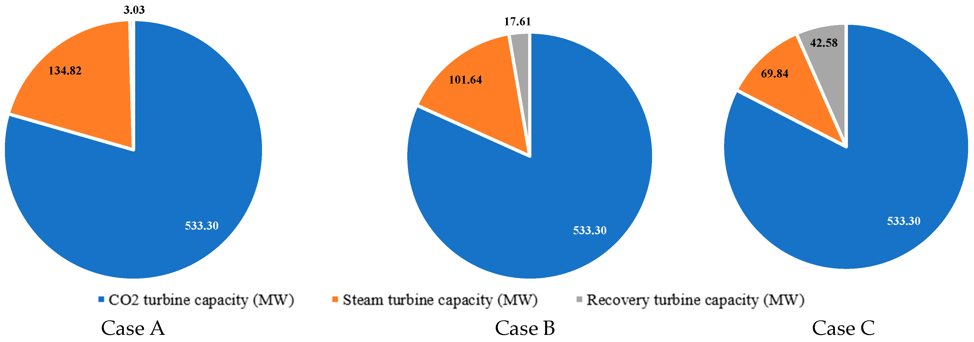
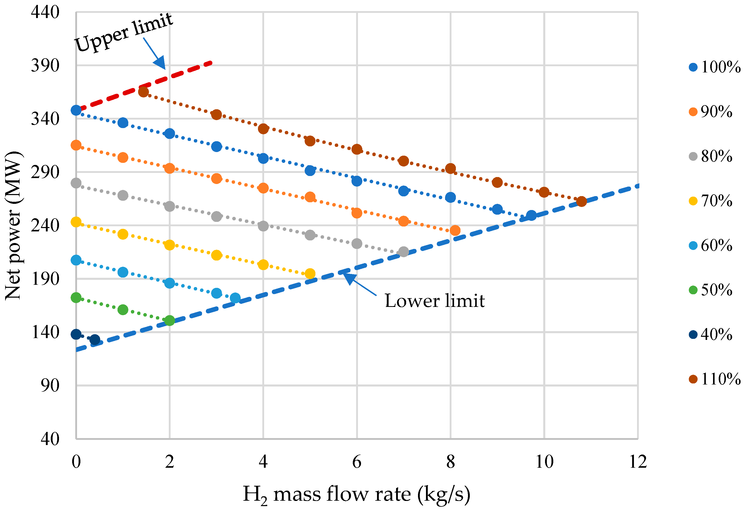
- The simulation results show that with an increase in the mass flow of hydrogen from 0 to 8 kg/s, the gross power of the power unit decreases by 25.4%. This is mainly due to additional own needs to maintain the operation of the methane steam conversion plant, which is why electricity costs increase by 90 MW.
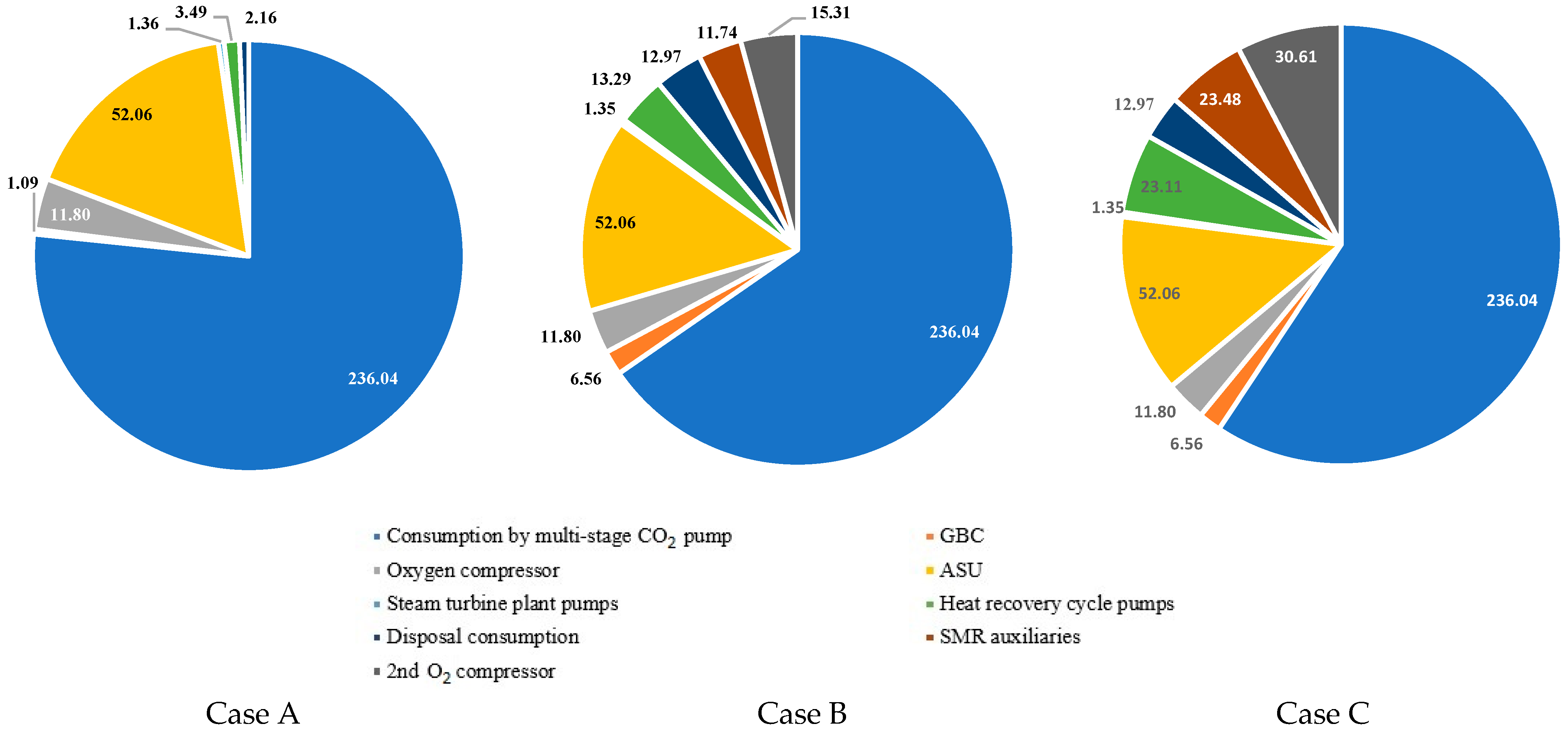
- It is established that, as a percentage of all own needs of the energy unit, the energy costs of a multistage carbon dioxide compressor are 76.6% for Case A, 65.4% for Case B, and 59.3% for Case C. This decrease is associated with additional costs for the operation of the SMR gas booster compressor, the SMR O2 compressor, the SMR ASU, and the SMR CO2 compressor, the total capacity of which for Case B is 37.8 MW, and for Case C is 64.9 MW.
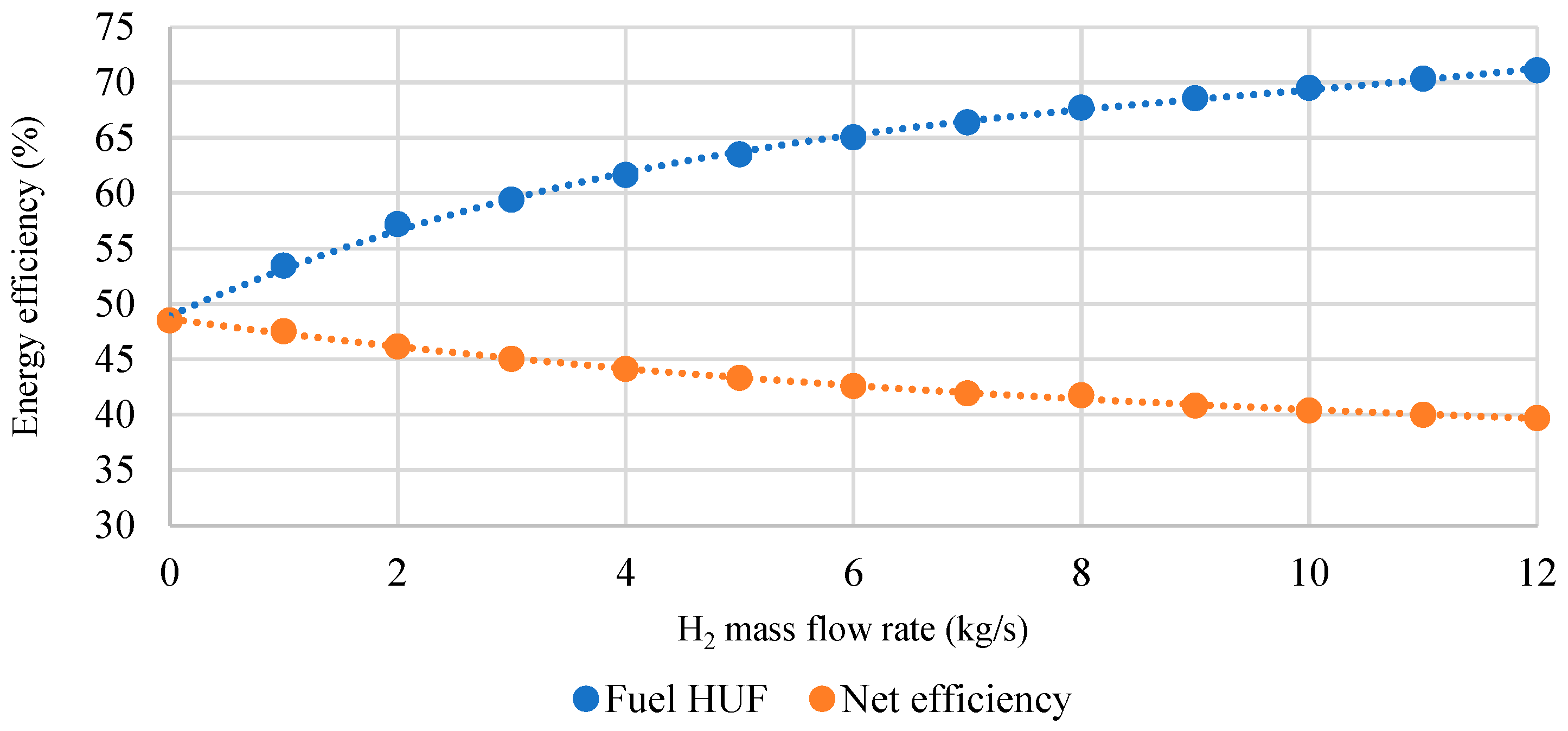
- The thermodynamic analysis of the developed oxy-fuel power complex with steam methane reforming showed that with a 12 kg/s increase in hydrogen output, the net efficiency of the combined power unit drops by 8.8%. This effect is due to a decrease in the flow rate of the working flow in the MP turbine, which reduces the electrical power generation and leads to higher pressure losses in the throttling valve. Due to lower losses in the condenser in the combined generation of electricity and H2, the fuel HUF of the oxy-fuel energy complex with SMR grows by 23.5%.
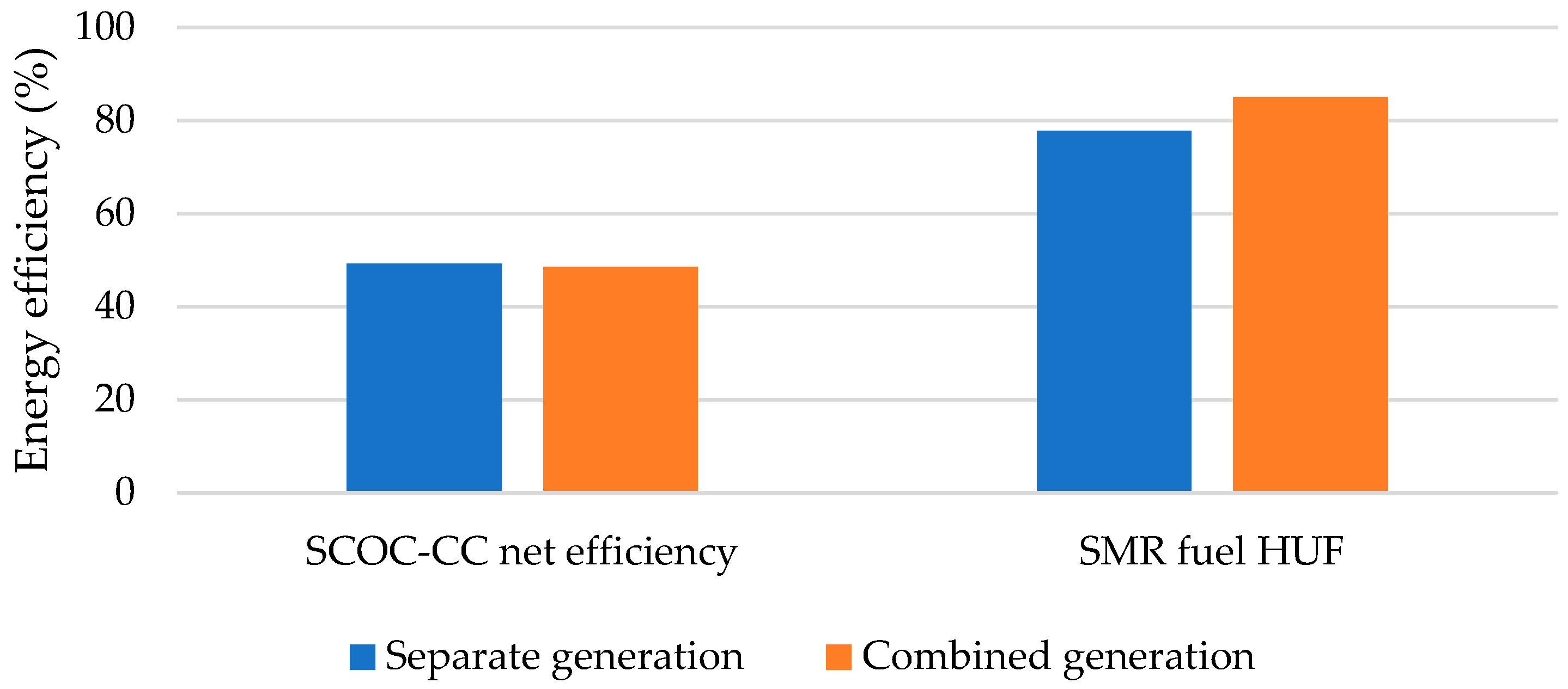
- The net efficiency of separate generation has been found to exceed that of combined generation by 0.67%, which is due to the fact that in the combined generation of electrical power and H2, a smaller amount of the coolant is able to perform in the MP and LP turbines. However, fuel HUF of the steam methane reformer in the combined generation of electrical power and H2 increases by 7.24%. This is due to lower heat supply to the combustion chamber for heating methane and steam entering the reformer.
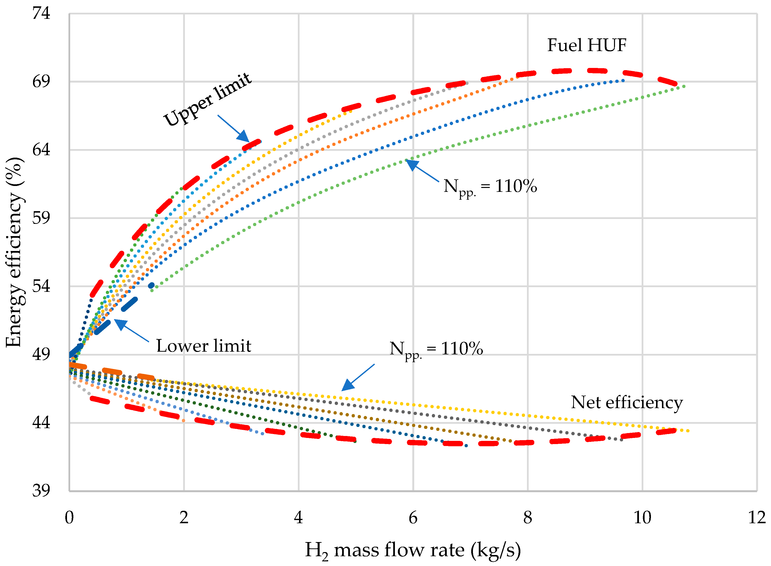
- Parameter charts have been developed as the tools for determining the net power, HUF, and net efficiency with changes in generation of electricity and H2 by the gas turbine. The study has shown that the capacity of an oxy-fuel plant with steam methane reforming ranges from 123.6 to 370.0 MW, the power unit’s hydrogen output is 0–10.8 kg/s, while the fuel heat utilization factor varies within the range of 47.2–70.1%.
Author Contributions
Funding
Conflicts of Interest
References
- Lisin, E.; Kurdiukova, G.; Okley, P.; Chernova, V. Efficient Methods of Market Pricing in Power Industry within the Context of System Integration of Renewable Energy Sources. Energies 2019, 12, 3250. [Google Scholar] [CrossRef] [Green Version]
- Rogalev, N.; Sukhareva, E.; Mentel, G.; Brozyna, J. Economic Approaches for Improving Electricity Market. Terra Econ. 2018, 16, 140–149. [Google Scholar]
- Atkinson, A.; Messy, F.A. Measuring Financial Literacy: Results of the OECD/International Network on Financial Education (INFE) Pilot Study. 2012. Available online: https://www.oecd-ilibrary.org/finance-and-investment/measuring-financial-literacy_5k9csfs90fr4-en (accessed on 8 February 2023).
- Litvinenko, V.; Tcvetkov, P.; Dvoynikov, M.; Buslaev, G. Barriers to Implementation of Hydrogen Initiatives in the Context of Global Energy Sustainable Development. J. Min. Inst. 2020, 244, 428–438. [Google Scholar] [CrossRef]
- IE Kopteva, A.; Kalimullin, L.; Tcvetkov, P.; Soares, A. Prospects and Obstacles for Green Hydrogen Production in Russia. Energies 2021, 14, 718. [Google Scholar] [CrossRef]
- Amez, I.; León, D.; Ivannikov, A.; Kolikov, K.; Castells, B. Potential of CBM as an Energy Vector in Active Mines and Abandoned Mines in Russia and Europe. Energies 2023, 16, 1196. [Google Scholar] [CrossRef]
- Staffell, I.; Scamman, D.; Abad, A.V.; Balcombe, P.; Dodds, P.E.; Ekins, P.; Shah, N.; Ward, K.R. The role of hydrogen and fuel cells in the global energy system. Energy Environ. Sci. 2019, 12, 463–491. [Google Scholar]
- Ma, L.C.; Castro-Dominguez, B.; Kazantzis, N.K.; Ma, Y.H. Integration of membrane technology into hydrogen production plants with CO2 capture: An economic performance assessment study. Int. J. Greenh. Gas Control 2015, 42, 424–438. [Google Scholar]
- Anantharaman, R.; Jordal, K.; Roussanaly, S.; Fu, C.; Wahl, P.E.; Brakstad, E.; Riboldi, L.; Gilardi, C.; Clapis, A.; Mancuso, L.; et al. Understanding the cost of retrofitting CO2 capture to an integrated oil refinery. In Proceedings of the 14th International Conference on Greenhouse Gas Control Technologies, GHGT-14, Leeds, Melbourne, Australia, 21–25 October 2018; 6p. [Google Scholar]
- Collodi, G.; Azzaro, G.; Ferrari, N.; Santos, S.; Brown, J.; Cotton, B.; Lodge, S. IEAGHG,“Techno-Economic Evaluation of SMR Based Standalone (Merchant) Plant with CCS”, 2017/02, February 2017. Available online: https://ieaghg.org/exco_docs/2017-02.pdf (accessed on 8 February 2023).
- Yun, J.; Cho, K.; Lee, Y.D.; Yu, S. Four different configurations of a 5 kW class shell-and-tube methane steam reformer with a low-temperature heat source. Int. J. Hydrogen Energy 2018, 9, 4546–4562. [Google Scholar] [CrossRef]
- Descamps, C.; Bouallou, C.; Kanniche, M. Efficiency of an Integrated Gasification Combined Cycle (IGCC) power plant including CO2 removal. Energy 2008, 6, 874–881. [Google Scholar] [CrossRef]
- Raksajati, A.; Ho, M.T.; Wiley, D.E. Reducing the cost of CO2 capture from flue gases using aqueous chemical absorption. Ind. Eng. Chem. Res. 2013, 47, 16887–16901. [Google Scholar] [CrossRef]
- Chen, W.; Zhang, G.; Li, B.; Liu, M.; Liu, J. Simulation study on 660 MW coal-fired power plant coupled with a steam ejector to ensure NOx reduction ability. Appl. Therm. Eng. 2017, 111, 550–561. [Google Scholar] [CrossRef]
- Sohn, J.; Hwang, I.S.; Hwang, J. Improvement of ammonia mixing in an industrial scale selective catalytic reduction De-NOx system of a coal-fired power plant: A numerical analysis. Process Saf. Environ. Prot. 2021, 147, 334–345. [Google Scholar]
- Ma, T.; Takeuchi, K. Technology choice for reducing NOx emissions: An empirical study of Chinese power plants. Energy Policy 2017, 102, 362–376. [Google Scholar] [CrossRef] [Green Version]
- Dutta, R.; Nord, L.O.; Bolland, O. Selection and design of post-combustion CO2 capture process for 600 MW natural gas fueled thermal power plant based on operability. Energy 2017, 121, 643–656. [Google Scholar] [CrossRef] [Green Version]
- Mahmoudi, R.; Emrouznejad, A.; Khosroshahi, H.; Khashei, M.; Rajabi, P. Performance evaluation of thermal power plants considering CO2 emission: A multistage PCA, clustering, game theory and data envelopment analysis. J. Clean. Prod. 2019, 223, 641–650. [Google Scholar] [CrossRef] [Green Version]
- Kindra, V.O.; Milukov, I.A.; Shevchenko, I.V.; Shabalova, S.I.; Kovalev, D.S. Thermodynamic analysis of cycle arrangements of the coal-fired thermal power plants with carbon capture. Arch. Thermodyn. 2021, 42, 103–121. [Google Scholar]
- Kanniche, M.; Le Moullec, Y.; Authier, O.; Hagi, H.; Bontemps, D.; Neveux, T.; Louis-Louisy, M. Up-to-date CO2 Capture in Thermal Power Plants. Energy Procedia 2017, 114, 95–103. [Google Scholar] [CrossRef]
- Peng, J.; Yu, B.-Y.; Liao, H.; Wei, Y.-M. Marginal abatement costs of CO2 emissions in the thermal power sector: A regional empirical analysis from China. J. Clean. Prod. 2018, 171, 163–174. [Google Scholar]
- Hong, J.; Chaudhry, G.; Brisson, J.G.; Field, R.; Gazzino, M.; Ghoniem, A.F. Analysis of oxy-fuel combustion power cycle utilizing a pressurized coal combustor. Energy 2009, 34, 1332–1340. [Google Scholar]
- Kindra, V.; Rogalev, A.; Zlyvko, O.; Sokolov, V.; Milukov, I. Research and development of a high-performance oxy-fuel combustion power cycle with coal gasification. Arch. Thermodyn. 2021, 42, 155–168. [Google Scholar]
- Kindra, V.; Osipov, S.; Zlyvko, O.; Shcherbatov, I.; Sokolov, V. Thermodynamic analysis of an innovative steam turbine power plant with oxy-methane combustors. Arch. Thermodyn. 2021, 42, 123–140. [Google Scholar]
- Barba, F.C.; Sanchez, G.M.D.; Segui, B.S.; Darabkhani, H.G.; Anthony, E.J. A technical evaluation, performance analysis and risk assessment of multiple novel oxy-turbine power cycles with complete CO2 capture. J. Clean. Prod. 2016, 133, 971–985. [Google Scholar] [CrossRef]
- Allam, R.; Martin, S.; Forrest, B.; Fetvedt, J.; Lu, X.; Freed, D.; Brown, G.W.; Sasaki, T.; Itoh, M.; Manning, J. Demonstration of the Allam Cycle: An update on the development status of a high efficiency supercritical carbon dioxide power process employing full carbon capture. Energy Procedia 2017, 114, 5948–5966. [Google Scholar]
- Zhang, N.; Lior, N. Two novel oxy-fuel power cycles integrated with natural gas reforming and CO2 capture. Energy 2008, 33, 340–351. [Google Scholar] [CrossRef]
- Ahn, J.H.; Jeong, J.H.; Choi, B.S.; Kim, T.S. Influence of various carbon capture technologies on the performance of natural gas-fired combined cycle power plants. J. Mech. Sci. Technol. 2019, 33, 1431–1440. [Google Scholar]
- Kindra, V.; Zlyvko, O.; Zonov, A.; Kovalev, D. An Oxy-Fuel Power Plant for Hydrogen Production with Near-Zero Emissions. In SMART Automatics and Energy: Proceedings of SMART-ICAE 2021; Springer Nature Singapore: Singapore, 2022; pp. 291–301. [Google Scholar]
- Rogalev, A.; Rogalev, N.; Kindra, V.; Zlyvko, O.; Vegera, A. A study of low-potential heat utilization methods for oxy-fuel combustion power cycles. Energies 2021, 14, 3364. [Google Scholar] [CrossRef]
- Peshev, D.; Livingston, A.G. OSN Designer, a tool for predicting organic solvent nanofiltration technology performance using Aspen One, MATLAB and CAPE OPEN. Chem. Eng. Sci. 2013, 104, 975–987. [Google Scholar] [CrossRef]
- Galashov, N.; Tsibulskiy, S.; Serova, T. Analysis of the Properties of Working Substances for the Organic Rankine Cycle Based Database “REFPROP”. EPJ Web Conf. 2016, 110, 01068. [Google Scholar] [CrossRef]
- Bălănescu, D.-T.; Homutescu, V.-M. Performance analysis of a gas turbine combined cycle power plant with waste heat recovery in Organic Rankine Cycle. Procedia Manuf. 2019, 32, 520–528. [Google Scholar]
- Fahim, M.A.; Al-Sahhaf, T.A.; Elkilani, A. Fundamentals of Petroleum Refining; Elsevier: Amsterdam, The Netherlands, 2009. [Google Scholar]





| Characteristics | Value |
|---|---|
| Ambient pressure, bar | 0.1 |
| Ambient temperature, °C | 15 |
| Fuel temperature, °C | 20 |
| Fuel pressure, bar | 7 |
| Fuel | 100% CH4 |
| Lower heating value for CH4 (at 15 °C and 7 bar), kJ/kg | 50 |
| Lower heating value for H2 (at 15 °C and 7 bar), kJ/kg | 130 |
| Inlet pump temperature, °C | 15 |
| Compressor isentropic/mechanical efficiency, % | 85/99 |
| Pump polytropic/mechanical efficiency, % | 75/99 |
| CO2 compressor/turbine polytropic efficiency, % | 85/99 |
| Pinch point temperature in the heater, °C | 5 |
| O2 purity, % | 95.6 |
| Reformer pressure, MPa | 2 |
| ASU delivery pressure, bar | 11 |
| ASU delivery temperature, °C | 30 |
| Specific energy consumption for the production of 1 kg of oxygen, kW/kg O2 | 1.093 |
| Characteristics | Units | Value |
|---|---|---|
| Temperature exhaust gases | °C | 90 |
| Pressure exhaust gases | bar | 1 |
| Mass flow flue gas | kg/s | 1 |
| Mass fraction CO2 | % | 2.60 |
| Mass fraction H2O | % | 2.13 |
| Mass fraction O2 | % | 19.29 |
| Mass fraction N2 | % | 75.98 |
| Characteristics | Units | Value |
|---|---|---|
| Outlet heat exchanger temperature | °C | 80 |
| Outlet separator temperature | °C | 30 |
| Outlet regenerated amine pump pressure | bar | 1.08 |
| Outlet saturated amine pump pressure | bar | 1.1 |
| Absorber column parameters | ||
| Number of stages | pc | 15 |
| Additional water supply per stage | pc | 1 |
| Flue gas supply to the stage | pc | 15 |
| Supply of regenerated amine | pc | 2 |
| Pressure in the first stage | bar | 1 |
| Stage pressure loss | bar | 0.05 |
| Recovery column parameters | ||
| Number of stages | pc | 15 |
| Carbon dioxide removal | pc | 1 |
| Withdrawal of regenerated amine | pc | 15 |
| Saturated amine feed | pc | 3 |
| Pressure in the first stage | bar | 1 |
| Stage pressure loss | bar | 0.05 |
| Reflux fraction in the condenser | - | 0.5 |
| Reboiler share | - | 0.7 |
| Characteristics | Value | Error, % | |
|---|---|---|---|
| Temperature, °C | 700 | ||
| Pressure, bar | 40 | ||
| H2O/CH4 ratio | 3 | ||
| Composition (vol%) | Math. model | Fahim M. A. At at | |
| CH4 | 13.2 | 13.13 | 0.530 |
| CO | 9.9 | 9.85 | 0.505 |
| CO2 | 9.3 | 9.36 | 0.645 |
| H2 | 67.6 | 67.66 | 0.089 |
| Value | Parameter | |
|---|---|---|
| Oxidizer | Air | Oxygen |
| Fuel mass flow in SMR, kg/s | 2.39 | 2.39 |
| Fuel mass flow in CC, kg/s | 0.49 | 0.78 |
| Hydrogen mass flow, kg/s | 1.00 | 1.00 |
| Air/carbon dioxide compressor power, kW | 16,735.03 | 49.57 |
| Fuel compressor power, kW | 106.26 | 165.31 |
| Oxygen compressor power, kW | - | 1285.23 |
| Monoethanolamine pumps power, kW | 5.53 | - |
| 20.24 | - | |
| CO2 storage power, kW | 1304.25 | 670 |
| ASU cost, kW | - | 4999.44 |
| Reboiler power, kW | 14,442.78 | 670 |
| CO2 capture, % | 89.1 | 99 |
| Fuel HUF, % | 76.10 | 84.25 |
| No. | Characteristics | Value |
|---|---|---|
| 1 | Lower heating value for CH4, kJ/kg | 50,025 |
| 2 | Fuel temperature, °C | 15 |
| 3 | Fuel pressure, bar | 7 |
| 4 | Fuel compressor isentropic/mechanical efficiency, % | 80/99 |
| 5 | Mechanical efficiency, % | 99 |
| 6 | Generator electricity/mechanical efficiency, % | 98.5/99.4 |
| 7 | Combustor pressure drop, % | 4 |
| 8 | Minimum cycle temperature, °C | 30 |
| 14 | CO2 turbine inlet mass flow, kg/s | 100 |
| 15 | HP steam temperature °C | 560 |
| HP steam pressure, MPa | 14 | |
| 16 | LP steam pressure, bar | 7 |
| 17 | Condenser pressure in steam turbine unit, bar | 0.045 |
| 18 | Deaerator operating pressure, bar | 1.21 |
| 19 | Steam turbine polytropic efficiency, % | 89 |
| 20 | Pump polytropic efficiency, % | 70 |
| 22 | Gas pressure drop in the heat recovery steam generator, Pascal | 100 |
| 23 | HP superheater minimum pinch, °C | 20 |
| 24 | ASU power consumption, kW/(kg/s) | 900 |
| 25 | O2 purity, % | 91.25 |
| 29 | Condenser efficiency | 0.8 |
| Ambient temperature, °C | 15 | |
| Ambient pressure, bar | 1.013 |
Disclaimer/Publisher’s Note: The statements, opinions and data contained in all publications are solely those of the individual author(s) and contributor(s) and not of MDPI and/or the editor(s). MDPI and/or the editor(s) disclaim responsibility for any injury to people or property resulting from any ideas, methods, instructions or products referred to in the content. |
© 2023 by the authors. Licensee MDPI, Basel, Switzerland. This article is an open access article distributed under the terms and conditions of the Creative Commons Attribution (CC BY) license (https://creativecommons.org/licenses/by/4.0/).
Share and Cite
Kindra, V.; Rogalev, A.; Oparin, M.; Kovalev, D.; Ostrovsky, M. Research and Development of the Oxy-Fuel Combustion Power Cycle for the Combined Production of Electricity and Hydrogen. Energies 2023, 16, 5983. https://doi.org/10.3390/en16165983
Kindra V, Rogalev A, Oparin M, Kovalev D, Ostrovsky M. Research and Development of the Oxy-Fuel Combustion Power Cycle for the Combined Production of Electricity and Hydrogen. Energies. 2023; 16(16):5983. https://doi.org/10.3390/en16165983
Chicago/Turabian StyleKindra, Vladimir, Andrey Rogalev, Maksim Oparin, Dmitriy Kovalev, and Mikhail Ostrovsky. 2023. "Research and Development of the Oxy-Fuel Combustion Power Cycle for the Combined Production of Electricity and Hydrogen" Energies 16, no. 16: 5983. https://doi.org/10.3390/en16165983
APA StyleKindra, V., Rogalev, A., Oparin, M., Kovalev, D., & Ostrovsky, M. (2023). Research and Development of the Oxy-Fuel Combustion Power Cycle for the Combined Production of Electricity and Hydrogen. Energies, 16(16), 5983. https://doi.org/10.3390/en16165983


