
Review of Methods for Diagnosing the Degradation Process in Power Units Cooperating with Renewable Energy Sources Using Artificial Intelligence

Abstract
:1. Introduction
- Fault detection: detection or observation of a fault occurring in the object and determination of the detection time [58];
- Fault isolation: isolation, determination of type, size, and time of the fault’s occurrence [59];
- Fault identification: determination of the size and character of the fault’s variability in time [43].
1.1. Literature Gap

| Author | Literature Source | Type of Analyzed Turbine: Steam and/or Gas and/or ORC | The Way of Locating the Degradation in the Turbine | Additional Remarks |
|---|---|---|---|---|
| Zhou et al. | [69] | Gas turbine | Convolution neural networks | |
| Fast, Palme’ | [68] | Gas turbine with its heat recovery steam generator and a biomass-fueled boiler with its steam cycle | ANN | |
| Ślęzak-Żołna, Głuch | [113] | Steam turbine | ANN | |
| Ślęzak-Żołna | [100] | Steam turbine | ANN | |
| Głuch, Drosińska-Komor | [92] | Steam turbine | ANN | |
| Głuch | [95] | Steam turbine | ANN | |
| Gardzilewicz et al. | [101] | Steam turbine | Statistical iterative | |
| Butterweck, Głuch | [114] | Steam turbine | Neural model | Modeling CFD. |
| Nowak, Rusin | [102] | Steam turbine | GA + FEM | Shape optimization of selected areas of the rotor of the high-pressure part of an ultra-supercritical steam turbine and the optimization of the turbine startup method. |
| Barelli et al. | [103] | The turbocharging system of a 1 MW internal combustion engine (I.C.E.) | The fuzzy logic | Specifically for the filters and compressor modules. |
| Zuming, Karimi | [104] | Combined cycle gas turbine (CCGT) power plants | Simulators such as GateCycle, Aspen HYSYS | |
| Zhou et al. | [105] | Gas turbine | Support vector machine | |
| Wong et al. | [106] | Gas turbine | Extreme learning machine | The comparison between extreme learning machines and support vector machines (SVM) was also made. |
| Yan et al. | [99] | Steam turbine generator | Hierarchical fuzzy CMAC neural network | |
| Tsoutsanis et al. | [107] | Gas turbine | Matlab’s built-in nonlinear unconstrained optimization algorithm is known as ‘‘fminsearch” in the performance adaptation process. | Adaptive diagnostics method. |
| Tsoutsanis et al. | [108] | Gas turbine | The performance adaptation process. | A model that was developed in Matlab/Simulink. |
| Barad et al. | [109] | Gas turbine engine | Neural network | |
| Madhavan et al. | [110] | Aero gas turbine engine | Three-dimensional (3D) finite element (FE) | Turbine rotor blade vibration. |
| Kuo | [96] | Gas turbine | ANN and fuzzy Logic | Turbine blade faults in fan turbo-jet. |
| Aslanidou et al. | [111] | Micro gas turbine | Machine learning | |
| Sławiński et al. | [112] | Gas turbine | The COM-GAS numerical code and FEM | Presents the ravages of second rotor stage failure in a gas turbine. |
| Angelakis et al. | [115] | Gas turbine | ANN | Diagnose blade faults. |
| Aretakis et al. | [116] | Gas turbine | Wavelet analysis | Vibration, unsteady pressure, and acoustic measurements are used to diagnose turbine faults. |
| Li, Nilkitsaranont | [117] | Gas turbine | Non-linear diagnostic regression techniques, including both linear and quadratic models, | |
| Breikin et al. | [118] | Aero gas turbine engine | GA | Dynamic modeling. |
| Fentaye et al. | [119] | Gas turbine | Bayesian network | Used adaptive gas path analysis (AGPA). |
| Dhini et al. | [120] | Steam turbine | Extreme learning machine-radial basis function networks | ELM-RBF was a comparison with back propagation neural network (BPNN). |
| Yang et al. | [121] | Steam turbine | Knowledge graph and Bayesian network | |
| Salahshoor et al. | [88] | Steam turbine | Fusion of a support vector machine classifier with an adaptive neuro-fuzzy inference system classifier, | |
| Zeng et al. | [122] | Gas turbine | Dynamic simulation model and Cuckoo search algorithm | The model was developed in the environment of Matlab/Simulink. |
| Salilew et al. | [123] | Gas turbine | Gas path non-linear steady-state model | |
| Yang et al. | [124] | Gas turbine | Kalman filter | |
| Asgari et al. | [125] | Gas turbine | ANN | |
| Mo et al. | [126] | Gas turbine | Fuzzy inference logic | |
| Zhang et al. | [127] | Steam turbine | Bayesian network | |
| Chmielniak and Trela | [128] | Steam turbine | ANN and Bayesian network | |
| Bzymek et al. | [129] | Steam turbine | Computational Solid Dynamic coupled Computational Fluid Dynamic | Process of improving the safety and reliability of operation of the 18K370 steam turbines Opole Power Plant. |
| Banaszkiewicz | [130] | Steam turbine | FEM + Duhamel’s integral | |
| Banaszkiewicz | [131] | Steam turbine | probabilistic analysis and fracture mechanics considerations | |
| Banaszkiewicz and Rehmus-Forc | [132] | Steam turbine | Material testing and mechanical integrity calculations | |
| Kraszewski et al. | [133] | Spherical bifurcation pipe of a live steam | A one-sided numerical thermal-FSI analysis | Element of a block of coal-fired power plant working with a 18K370 turbine. |
| Badur et al. | [134] | Control stage in steam turbine | Studied analytically and numerically | Combination of CFD + CSD, often called FSI (Fluid–Solid Interaction or Fluid–Structure Interaction). |
| Badur et al. | [135] | Steam turbine–rotor and casting | Thermal-FSI (Fluid–Solid Interaction) | |
| Madejski et al. | [136] | Utility boilers | CFD calculations | |
| Blaut, Breńkacz | [137] | Rotor unbalance | Teager–Kaiser energy operator (TKEO) | |
| Andrearczyk et al. | [138] | Prototypical microturbine operating in an ORC-based power plant | Use LabVIEW | Vibrodiagnostic system designed. |
| Badur et al. | [139] | Heat exchanger | “Thermal-FSI” (“Fluid–Solid Interaction”) | |
| Ziółkowski et al. | [140] | Steam and gas turbine | COM GAS | |
| Ziółkowski et al. | [141] | ORC | COM GAS | |
| Ziółkowski et al. | [142] | Steam turbine | ECO PG, CFD | |
| Lampart et al. | [143] | ORC | Hybrid algorithms | |
| Niksa-Rynkiewicz et al. | [144] | Gas turbine | ANN |
1.2. Purpose and Structure of the Article
2. Methodology Obtaining a Diagnosis in Thermal and Flow System
2.1. Genetic Algorithms
- First, the whole algorithm is initiated by creating an initial population.
- Then, the chromosome adaptation in the population is assessed, and this concerns each chromosome in the population.
- The third stage concerns the stopping condition and depends on the method of applying a genetic algorithm. Two stopping conditions can occur. The first one occurs when the problem being analyzed involves an optimization task. Here, the decisive condition may be determining the optimum value (minimum or maximum). Another case may occur after the algorithm has been in operation for a specified time or when its operation does not lead to any improvement in the result obtained.
- The fourth stage introduces chromosome selection: to create a population, chromosomes with the highest value of adaptation are selected [158]. Ranking selection is used in thermal and flow diagnostics.
- The fifth stage concerns the genetic operator, which creates a population out of chromosomes obtained after the fourth stage. This is where the crossover and mutation operators can be distinguished. The crossover operator is more frequently used than the mutation operator [159].
- The penultimate stage involves creating a new population obtained after applying operators from the preceding stage. The new population can thus be subject to a specified action, i.e., checking the algorithm-stopping condition or introducing a specified chromosome.
- The last stage involves introducing the “best” chromosome; this occurs when the stopping condition is met. Such action enables the result for the entire genetic algorithm to be obtained [160].
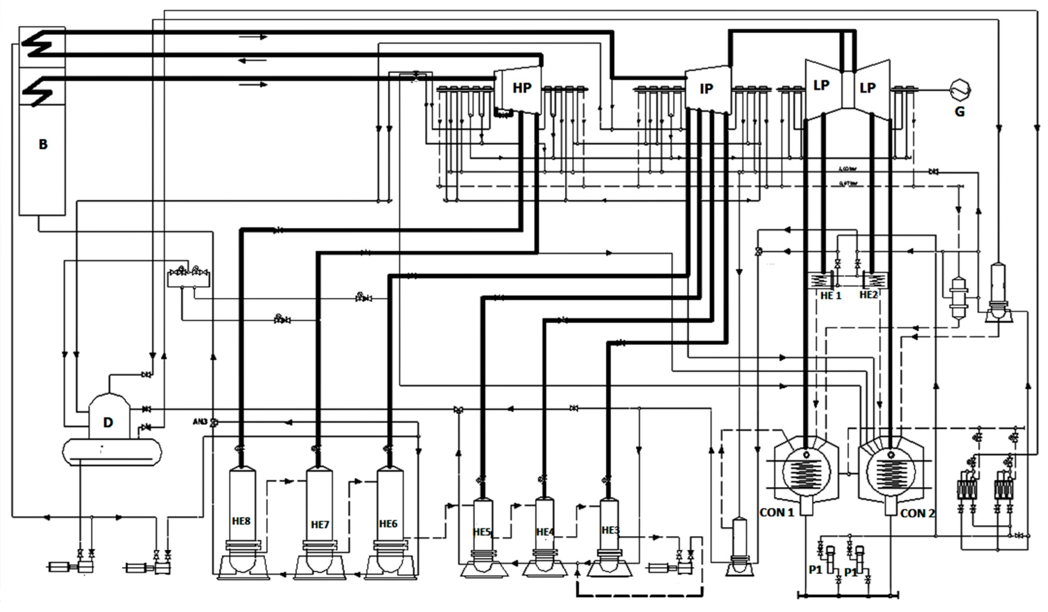
2.2. Description of the Analyzed System
- Pressures;
- Mass flows;
- Temperatures;
- Currents and voltages supplying the motors installed on the power unit;
- Electric power.
2.3. Studied Genetic Procedures
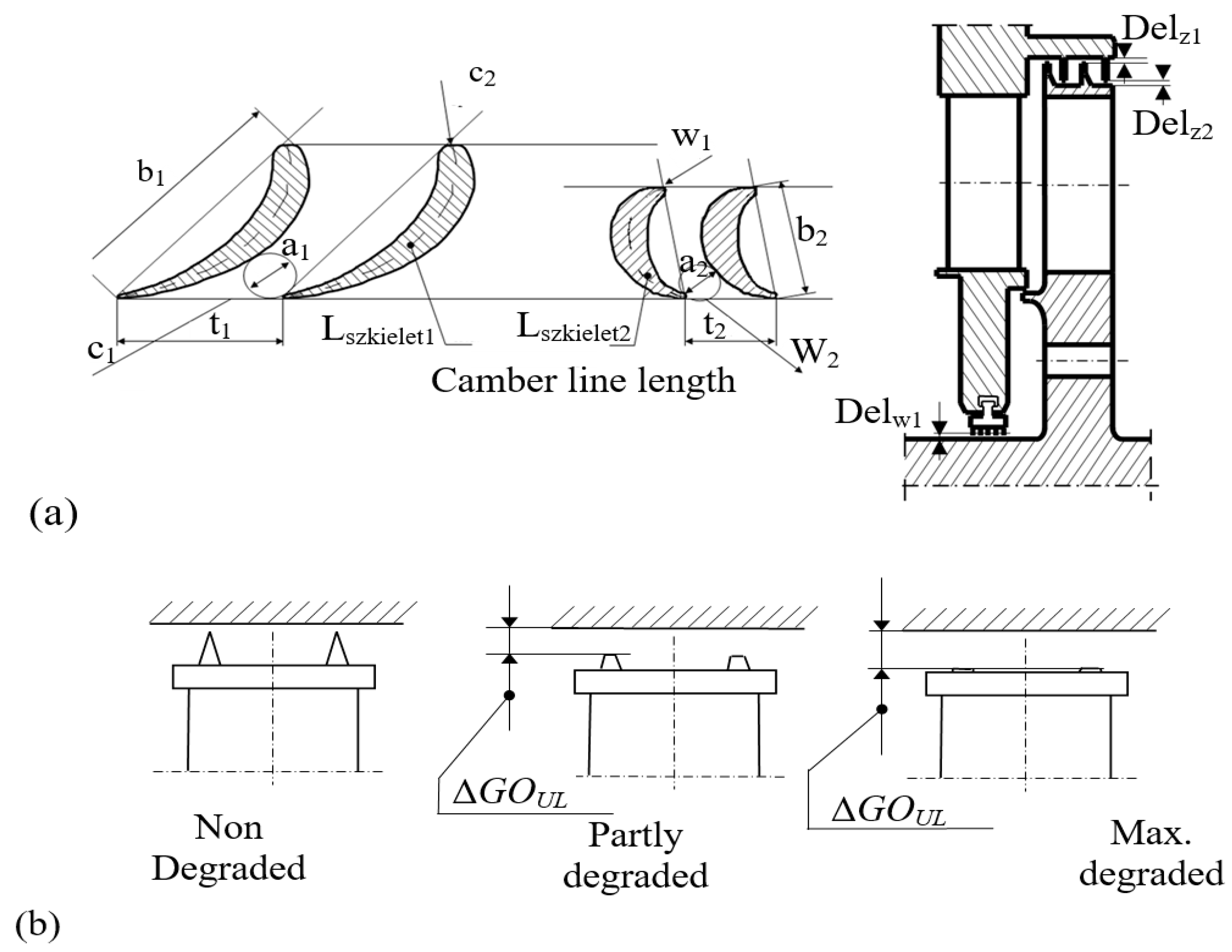
- The first stage of the software is to prepare geometric data sets (e.g., Figure 2) for the calculation process.
- In the following phase, symptoms and signatures are determined by numerical simulation using the DIAGAR program.
- The third stage involves simulating and sampling a single degradation and then determining symptoms and signatures for the degradation.
- 4.
- The next step is to sample and perform crossover operations using geometric data subject to operational degradation. This aims to determine the component device of the cycle, for which crossover will be carried out and as a result of which the level of degradation formed is obtained.
- 5.
- After performing the above operations, a geometric data set is constructed for new data created after the crossover. At the moment, only one fault is analyzed, which can occur at any time on one of six component devices, for which six suitable searching signatures are created by performing six appropriate calculations for the relevant thermal cycle using DIAGAR software in preparation for the next phase.
- 6.
- In the sixth phase, the specialized software calculates symptoms for six datasets, accumulates them in six searching signatures, and then subjects them to the selection process.
- 7.
- In the seventh phase, the selection is carried out as mentioned earlier in the article. More precisely, the process consists of selecting the two signatures closest to the present signature. This assumption is met when the condition of a location below the minimum distance is met for at least one signature. It is one of the most difficult phases. Therefore, the authors made a big effort to accelerate and gain better accuracy of the recognition decision choosing signatures for further operation in proper order. For numerical procedures, finding appropriate single numbers defining each signature helped achieve the purpose mentioned above.
- 8.
- The moment of meeting such a condition is described as a solution. If this condition cannot be met, the fourth phase is repeated. This involves creating new data files on the two parameters closest to degradation. Files with data are subjected to the following phases mentioned above until a solution is obtained.
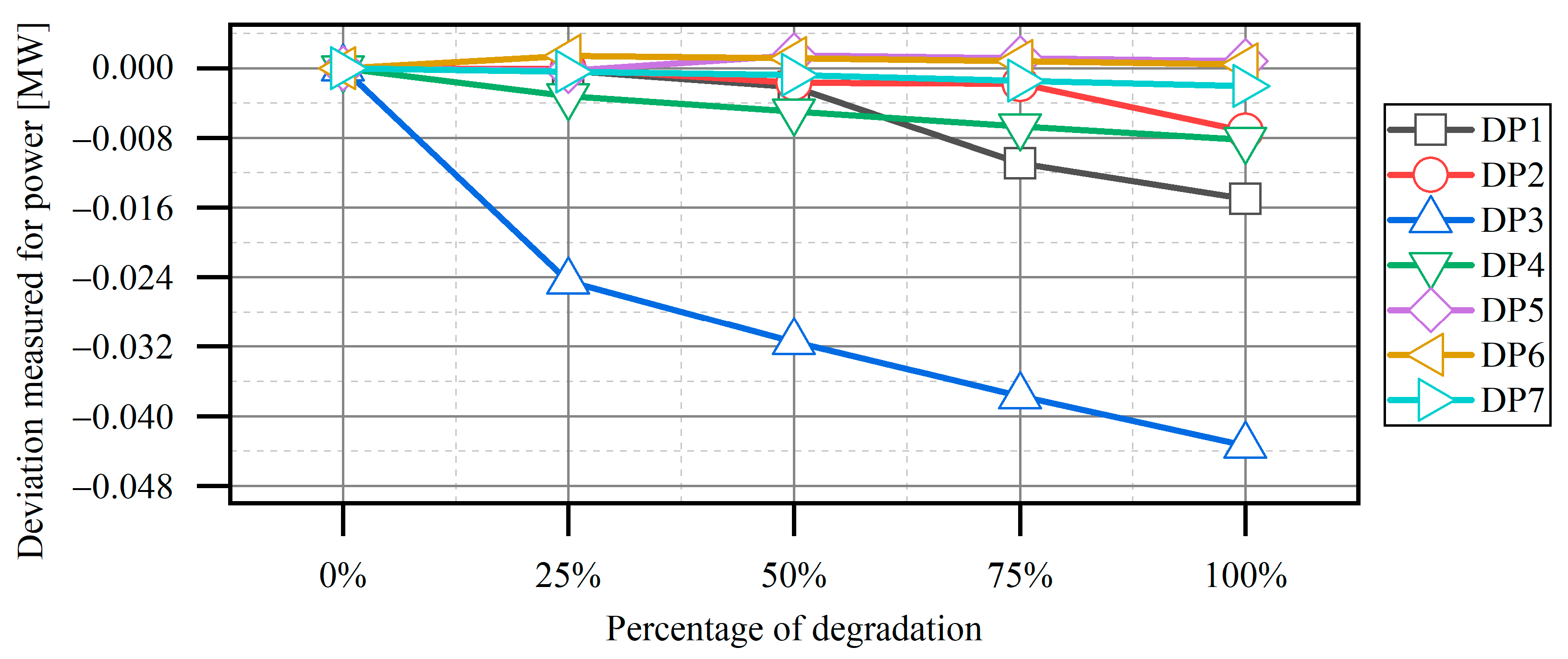
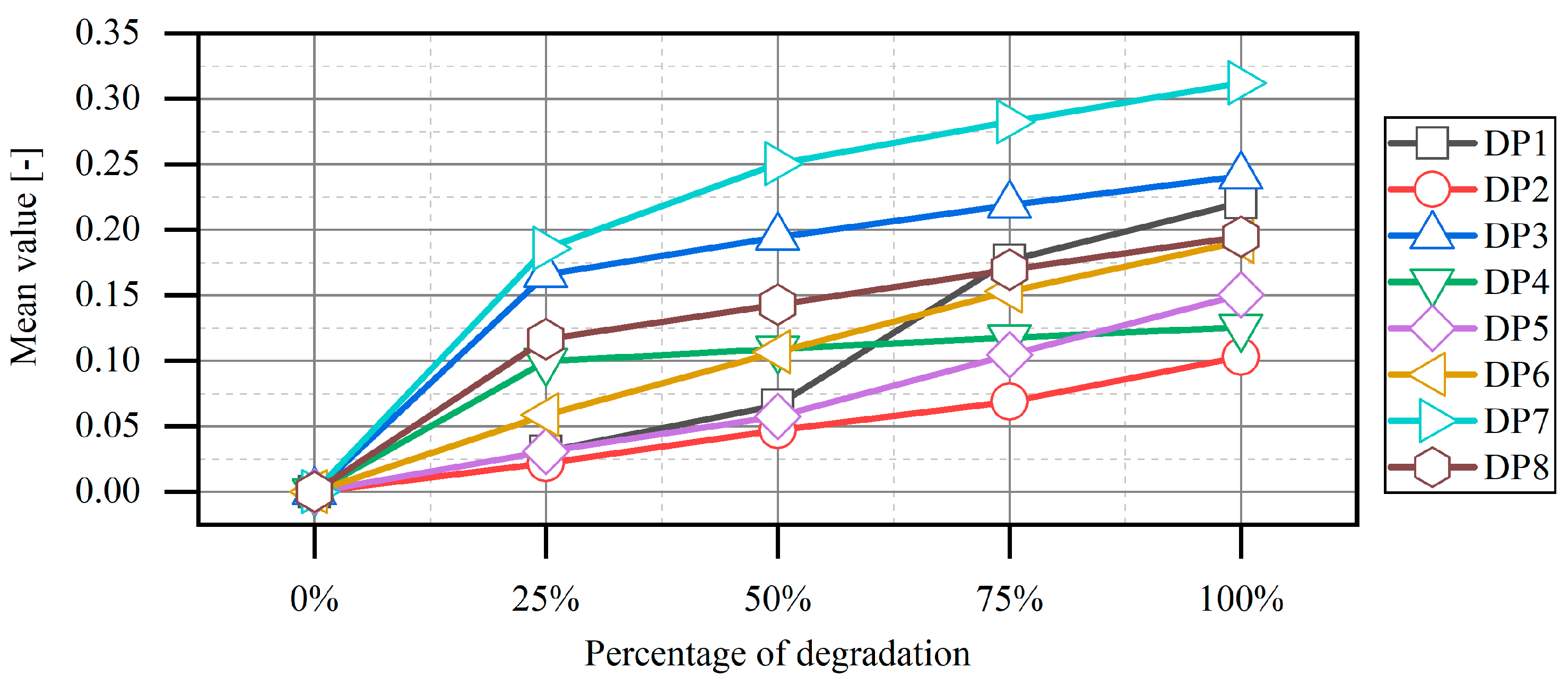
3. Procedure Selection and Creation of Characteristics
| Symbol | Name | Degradation Description |
|---|---|---|
 | DP1 | Clearance in the seal of the control valve nozzle box for HP parts |
 | DP2 | Clearance in the outer seal of the HP part |
 | DP3 | Clearances in the seals for 1 stage group of HP parts |
 | DP4 | Clearances in the seals for 2 stage group of HP parts |
 | DP5 | Clearance in the sealing of the IP control valve nozzle box |
 | DP6 | Clearance in the external sealing of the IP part |
 | DP7 | Clearances in the seals for 3 stage group of IP parts |
 | DP8 | Clearances in the seals for 4 stage group of IP parts |
 | DP9 | Clearances in the seals for 5 stage group of HP parts |
 | DP10 | Clearances in the seals for 6 stage group of HP parts |
3.1. Crossover Operations on Chromosomes—Values of Geometric Parameters
3.2. Selection
- Preliminary selection based on selected characteristics;
- Final selection based on complete signatures.
3.3. Characteristics
4. Summary and Perspective
Author Contributions
Funding
Data Availability Statement
Conflicts of Interest
Nomenclature
| a1 | Stator throat diameter |
| a2 | Rotor throat diameter |
| AGPA | Adaptive gas path analysis |
| AHP | Absorption heat pump |
| AFARN | Adaptive Fault Attention Residual Network |
| AI | Artificial intelligence |
| ANN | Artificial neutral networks |
| B | Coal-fired boiler |
| b1 | Stator chord |
| b2 | Rotor chord |
| BECCS | BioEnergy with Carbon Capture and Storage |
| BPNN | Back propagation neural network |
| C1 | Stator absolute velocity |
| C2 | Rotor outlet absolute velocity |
| CCGT | Combined cycle gas turbine |
| CFD | Computational Fluid Dynamics |
| CMAC | Cerebellar Model Articulation Controller |
| CON | Steam condenser |
| D | Deaerator |
| Delz1 | Stage external glands clearance |
| Delw1 | Internal ordinary gland segment clearance |
| DHX | Dedicated heat exchanger |
| DP | Degradation parameter |
| ECO PG | Program name from Ecological Poli-Generation systems |
| FEM | Finite Element Method |
| FSI | Fluid–Solid Interaction |
| G | Electric generator |
| GA | Genetic algorithms |
| HE | Regenerative heat exchangers |
| HP | High-pressure steam turbine |
| I.C.E. | Internal combustion engine |
| IP | Intermediate pressure steam turbine |
| Lszkiel1 | Stator blade camber line length |
| Lszkiel2 | Rotor blade camber line length |
| LP | Low pressure steam turbine |
| MOGA | Multi-objective genetic algorithm |
| ORC | Organic Rankine Cycle |
| P1 | Condensate pump |
| RES | Renewable Energy Sources |
| SWOT | Strengths–Weaknesses–Opportunities–Threats |
| SVM | Support vector machines |
| t1 | Stator pitch |
| t2 | Rotor pitch |
| TFD | Thermal-Flow Diagnostics |
| TKEO | Teager–Kaiser energy operator |
| w1 | Rotor inlet relative velocity |
| w2 | Rotor outlet relative velocity |
References
- Suo, M.Q.; Li, Y.P.; Huang, G.H. Multicriteria Decision Making under Uncertainty: An Advanced Ordered Weighted Averaging Operator for Planning Electric Power Systems. Eng. Appl. Artif. Intell. 2012, 25, 72–81. [Google Scholar] [CrossRef]
- Javadi, M.; Jafari, N.; Khalili, M.; Jabery, R. 4E Analysis of Three Different Configurations of a Combined Cycle Power Plant Integrated with a Solar Power Tower System. Sustain. Energy Technol. Assess. 2021, 48, 101599. [Google Scholar] [CrossRef]
- Drosińska-Komor, M.; Głuch, J.; Breńkacz, L.; Ziółkowski, P. On the Use of Selected 4th Generation Nuclear Reactors in Marine Power Plants. Polish Marit. Res. 2022, 29, 76–84. [Google Scholar] [CrossRef]
- Szewczuk-Krypa, N.; Drosińska-Komor, M.; Głuch, J.; Breńkacz, Ł. Comparison Analysis of Selected Nuclear Power Plants Supplied With Helium from High-Temperature Gas-Cooled Reactor. Polish Marit. Res. 2018, 25, 204–210. [Google Scholar] [CrossRef]
- Madejski, P.; Taler, D.; Taler, J. Thermal and Flow Calculations of Platen Superheater in Large Scale CFB Boiler. Energy 2022, 258, 124841. [Google Scholar] [CrossRef]
- Karaçor, M.; Uysal, A.; Mamur, H.; Günnur, S. Life Performance Prediction of Natural Gas Combined Cycle Power Plant with Intelligent Algorithms. Sustain. Energy Technol. Assess. 2021, 47, 101398. [Google Scholar] [CrossRef]
- Bae, S.J.; Mun, B.M.; Chang, W.; Vidakovic, B. Condition Monitoring of a Steam Turbine Generator Using Wavelet Spectrum Based Control Chart. Reliab. Eng. Syst. Saf. 2019, 184, 13–20. [Google Scholar] [CrossRef]
- Witanowski, Ł.; Ziółkowski, P.; Klonowicz, P.; Lampart, P. A Hybrid Approach to Optimization of Radial Inflow Turbine with Principal Component Analysis. Energy 2023, 272, 127064. [Google Scholar] [CrossRef]
- Mukoni, E.; Garner, K.S. Multi-Objective Non-Dominated Sorting Genetic Algorithm Optimization for Optimal Hybrid (Wind and Grid)-Hydrogen Energy System Modelling. Energies 2022, 15, 7079. [Google Scholar] [CrossRef]
- Madejski, P.; Chmiel, K.; Subramanian, N.; Kuś, T. Methods and Techniques for CO2 Capture: Review of Potential Solutions and Applications in Modern Energy Technologies. Energies 2022, 15, 887. [Google Scholar] [CrossRef]
- Ziółkowski, P.; Głuch, S.; Ziółkowski, P.J.; Badur, J. Compact High Efficiency and Zero-Emission Gas-Fired Power Plant with Oxy-Combustion and Carbon Capture. Energies 2022, 15, 2590. [Google Scholar] [CrossRef]
- Drosińska-Komor, M.; Głuch, J.; Brzezińska-Gołębiewska, K.; Piotrowicz, M.; Ziółkowski, P. Conditions for Increasing the Recognition of Degradation in Thermal-Flow Diagnostics, Taking into Account Environmental Legal Aspects. J. Power Technol. 2023, 103, 33–48. [Google Scholar]
- Kaushik, E.; Prakash, V.; Mahela, O.P.; Khan, B.; Abdelaziz, A.Y.; Hong, J.; Geem, Z.W. Optimal Placement of Renewable Energy Generators Using Grid-Oriented Genetic Algorithm for Loss Reduction and Flexibility Improvement. Energies 2022, 15, 1863. [Google Scholar] [CrossRef]
- Skowron, Ł.; Chygryn, O.; Gąsior, M.; Koibichuk, V.; Lyeonov, S.; Drozd, S.; Dluhopolskyi, O. Interconnection between the Dynamic of Growing Renewable Energy Production and the Level of CO2 Emissions: A Multistage Approach for Modeling. Sustainability 2023, 15, 9473. [Google Scholar] [CrossRef]
- Fernández, J.R. An Overview of Advances in CO2 Capture Technologies. Energies 2023, 16, 1413. [Google Scholar] [CrossRef]
- Ekardt, F.; Roos, P.; Bärenwaldt, M.; Nesselhauf, L. Energy Charter Treaty: Towards a New Interpretation in the Light of Paris Agreement and Human Rights. Sustainability 2023, 15, 5006. [Google Scholar] [CrossRef]
- Szewczuk-Krypa, N.; Grzymkowska, A.; Głuch, J. Comparative Analysis of Thermodynamic Cycles of Selected Nuclear Ship Power Plants with High-Temperature Helium-Cooled Nuclear Reactor. Polish Marit. Res. 2018, 25, 218–224. [Google Scholar] [CrossRef]
- Özgür-Ünlüakın, D.; Türkali, B.; Karacaörenli, A.; Çağlar Aksezer, S. A DBN Based Reactive Maintenance Model for a Complex System in Thermal Power Plants. Reliab. Eng. Syst. Saf. 2019, 190, 106505. [Google Scholar] [CrossRef]
- Gotzman, S.; Ziόłkowski, P.; Badur, J. Evaluati on of Long-Term Start up Costs Impact on Short-Term Price Based Operational Optimization of a CCGT Using MILP. E3S Web Conf. 2019, 137, 01012. [Google Scholar] [CrossRef]
- Woolley, E.; Luo, Y.; Simeone, A. Industrial Waste Heat Recovery: A Systematic Approach. Sustain. Energy Technol. Assess. 2018, 29, 50–59. [Google Scholar] [CrossRef]
- Chen, Z.; Zhou, D.; Zio, E.; Xia, T.; Pan, E. Adaptive Transfer Learning for Multimode Process Monitoring and Unsupervised Anomaly Detection in Steam Turbines. Reliab. Eng. Syst. Saf. 2023, 234, 109162. [Google Scholar] [CrossRef]
- Liu, X.; Sun, Q.; Ye, Z.S.; Yildirim, M. Optimal Multi-Type Inspection Policy for Systems with Imperfect Online Monitoring. Reliab. Eng. Syst. Saf. 2021, 207, 107335. [Google Scholar] [CrossRef]
- Breńkacz, Ł.; Bagiński, P.; Adamowicz, M.; Giziewski, S. Failure Analysis of a High-Speed Induction Machine Driven by a SiC-Inverter and Operating on a Common Shaft with a High-Speed Generator. Eksploat. I Niezawodn.–Maint. Reliab. 2022, 24, 177–185. [Google Scholar] [CrossRef]
- Yang, T.; Wang, W.; Zeng, D.; Liu, J.; Cui, C. Closed-Loop Optimization Control on Fan Speed of Air-Cooled Steam Condenser Units for Energy Saving and Rapid Load Regulation. Energy 2017, 135, 394–404. [Google Scholar] [CrossRef]
- Madejski, P.; Michalak, P.; Karch, M.; Kuś, T.; Banasiak, K. Monitoring of Thermal and Flow Processes in the Two-Phase Spray-Ejector Condenser for Thermal Power Plant Applications. Energies 2022, 15, 7151. [Google Scholar] [CrossRef]
- Vidinopoulos, A.; Whale, J.; Fuentes, U. Assessing the Technical Potential of ASEAN Countries to Achieve 100% Renewable Energy Supply. Sustain. Energy Technol. Assess. 2020, 42, 100878. [Google Scholar] [CrossRef]
- Ziółkowski, P.; Stasiak, K.; Amiri, M.; Mikielewicz, D. Negative Carbon Dioxide Gas Power Plant Integrated with Gasification of Sewage Sludge. Energy 2023, 262, 125496. [Google Scholar] [CrossRef]
- Rahimzadeh, A.; Christiaanse, T.V.; Evins, R. Optimal Storage Systems for Residential Energy Systems in British Columbia. Sustain. Energy Technol. Assess. 2021, 45, 101108. [Google Scholar] [CrossRef]
- Peng, M.Y.; Chen, C.; Peng, X.; Marefati, M. Energy and Exergy Analysis of a New Combined Concentrating Solar Collector, Solid Oxide Fuel Cell, and Steam Turbine CCHP System. Sustain. Energy Technol. Assess. 2020, 39, 100713. [Google Scholar] [CrossRef]
- Amrollahi, Z.; Ystad, P.A.M.; Ertesvåg, I.S.; Bolland, O. Optimized Process Configurations of Post-Combustion CO2 Capture for Natural-Gas-Fired Power Plant–Power Plant Efficiency Analysis. Int. J. Greenh. Gas Control 2012, 8, 1–11. [Google Scholar] [CrossRef]
- Sanaye, S.; Khakpaay, N.; Chitsaz, A. Thermo-Economic and Environmental Multi-Objective Optimization of a Novel Arranged Biomass-Fueled Gas Engine and Backpressure Steam Turbine Combined System for Pulp and Paper Mills. Sustain. Energy Technol. Assess. 2020, 40, 100778. [Google Scholar] [CrossRef]
- Ziółkowski, P.; Badur, J.; Pawlak-Kruczek, H.; Stasiak, K.; Amiri, M.; Niedzwiecki, Ł.; Krochmalny, K.; Mularski, J.; Madejski, P.; Mikielewicz, D. Mathematical Modelling of Gasification Process of Sewage Sludge in Reactor of Negative CO2 Emission Power Plant. Energy 2021, 224, 122601. [Google Scholar] [CrossRef]
- Habibi, R.; Pourfayaz, F.; Mehrpooya, M.; Kamali, H. A Natural Gas-Based Eco-Friendly Polygeneration System Including Gas Turbine, Sorption-Enhanced Steam Methane Reforming, Absorption Chiller and Flue Gas CO2 Capture Unit. Sustain. Energy Technol. Assess. 2022, 52, 101984. [Google Scholar] [CrossRef]
- Rusin, A.M. Technical Risk Involved in Long-Term Operation of Steam Turbines. Reliab. Eng. Syst. Saf. 2007, 92, 1242–1249. [Google Scholar] [CrossRef]
- Valero, A.; Correas, L.; Zaleta, A.; Lazzaretto, A.; Verda, V.; Reini, M.; Rangel, V. On the Thermoeconomic Approach to the Diagnosis of Energy System Malfunctions Part 2. Malfunction Definitions and Assessment. Energy 2004, 29, 1889–1907. [Google Scholar] [CrossRef]
- Ghaffari, A.; Chaibakhsh, A.; Lucas, C. Soft Computing Approach for Modeling Power Plant with a Once-through Boiler. Eng. Appl. Artif. Intell. 2007, 20, 809–819. [Google Scholar] [CrossRef]
- Breńkacz, Ł.; Żywica, G.; Drosińska-Komor, M. The Experimental Identification of the Dynamic Coefficients of Two Hydrodynamic Journal Bearings Operating at Constant Rotational Speed and Under Nonlinear Conditions. Polish Marit. Res. 2017, 24, 108–115. [Google Scholar] [CrossRef]
- Breńkacz, Ł.; Żywica, G. Comparison of Experimentally and Numerically Determined Dynamic Coefficients of the Hydrodynamic Slide Bearings Operating in the Nonlinear Rotating System. In Proceedings of the ASME Turbo Expo 2017: Turbomachinery Technical Conference and Exposition, Charlotte, NC, USA, 26 June 2017; Volume 7A: Struct, pp. 1–12. [Google Scholar]
- Breńkacz, Ł.; Żywica, G.; Drosińska-Komor, M.; Szewczuk-Krypa, N. The Experimental Determination of Bearings Dynamic Coefficients in a Wide Range of Rotational Speeds, Taking into Account the Resonance and Hydrodynamic Instability. In Dynamical Systems in Applications; Awrejcewicz, J., Ed.; Springer Proceedings in Mathematics & Statistics; Springer International Publishing: Cham, Switzerland, 2018; Volume 249, pp. 13–24. ISBN 978-3-319-96600-7. [Google Scholar]
- Breńkacz, Ł.; Żywica, G. The Sensitivity Analysis of the Method for Identification of Bearing Dynamic Coefficients. In Dynamical Systems: Modelling; Springer: Berlin/Heidelberg, Germany, 2016; pp. 81–96. [Google Scholar]
- Błaszczyk, A.; Głuch, J.; Gardzilewicz, A. Operating and Economic Conditions of Cooling Water Control for Marine Steam Turbine Condensers. Polish Marit. Res. 2011, 18, 48–54. [Google Scholar] [CrossRef]
- Głuch, J. Fault Detection in Measuring Systems of Power Plants. Polish Marit. Res. 2008, 15, 45–51. [Google Scholar] [CrossRef]
- Głuch, J.; Ślęzak-Żołna, J. Solving Problems with Patterns for Heat and Flow Diagnostics Dedicated for Turbine Power Plants. In Proceedings of the International Gas Turbine Institute Proceedings ASME Turbo Expo 2012, Copenhagen, Denmark, 11–15 June 2012; Volume 1, pp. 969–979. [Google Scholar]
- Tabaszewski, M.; Cempel, C. Using a Set of GM (1, 1) Models to Predict Values of Diagnostic Symptoms. Mech. Syst. Signal Process. 2015, 52–53, 416–425. [Google Scholar] [CrossRef]
- Geete, A.; Khandwawala, A.I. To Analyse the Combined Effect of Different Extraction Line Pressure Drops on the Performance of Coal-Fired Thermal Power Plant. Int. J. Ambient Energy 2017, 38, 389–394. [Google Scholar] [CrossRef]
- Dominiczak, K.; Drosińska-Komor, M.; Rządkowski, R.; Głuch, J. Optimisation of Turbine Shaft Heating Process under Steam Turbine Run-up Conditions. Arch. Thermodyn. 2020, 41, 255–268. [Google Scholar] [CrossRef]
- Witanowski; Klonowicz, P.; Lampart, P.; Suchocki, T.; Jędrzejewski; Zaniewski, D.; Klimaszewski, P. Optimization of an Axial Turbine for a Small Scale ORC Waste Heat Recovery System. Energy 2020, 205, 118059. [Google Scholar] [CrossRef]
- Głuch, J.; Krzyżanowski, J. On Thermal Diagnostics of Turbomachinery Power Systems. In Proceedings of the 3rd European Conference on Turbomachinery: Fluid Dynamics and Thermodynamics, London, UK, 2–5 March 1999. [Google Scholar]
- Głuch, J. Selected Problems of Determining an Efficient Operation Standard in Contemporary Heat-and-Flow Diagnostics. Polish Marit. Res. 2009, 16, 22–28. [Google Scholar] [CrossRef]
- Macedo, L.L.; Godinho, P.; Alves, M.J. Mean-Semivariance Portfolio Optimization with Multiobjective Evolutionary Algorithms and Technical Analysis Rules. Expert Syst. Appl. 2017, 79, 33–43. [Google Scholar] [CrossRef]
- Li, C.; Niansu, H. Fault Diagnosis for Steam-Flow Exciting Vibration of Ultra Supercritical 1000MW Steam Turbine. Open Mech. Eng. J. 2015, 9, 1067–1075. [Google Scholar] [CrossRef]
- Kowalczyk, T.; Głuch, J.; Ziółkowski, P. Analysis of Possible Application of High-Temperature Nuclear Reactors to Contemporary Large-Output Steam Power Plants on Ships. Polish Marit. Res. 2016, 23, 32–41. [Google Scholar] [CrossRef]
- Babykina, G.; Brînzei, N.; Aubry, J.F.; Deleuze, G. Modeling and Simulation of a Controlled Steam Generator in the Context of Dynamic Reliability Using a Stochastic Hybrid Automaton. Reliab. Eng. Syst. Saf. 2016, 152, 115–136. [Google Scholar] [CrossRef]
- Jaskólski, M.; Reński, A.; Minkiewicz, T. Thermodynamic and Economic Analysis of Nuclear Power Unit Operating in Partial Cogeneration Mode to Produce Electricity and District Heat. Energy 2017, 141, 2470–2483. [Google Scholar] [CrossRef]
- Breńkacz, Ł.; Kędra, R.; Janicki, W.; Maurin, A.; Bagiński, P.; Andrearczyk, A.; Zima, B. Research on Linear Actuators for Active Foil Bearings. Materials 2022, 15, 5694. [Google Scholar] [CrossRef]
- Breńkacz, Ł. Identification of Stiffness, Damping and Mass Coefficients of Rotor-Bearing System Using Impulse Response Method. J. Vibroeng. 2015, 17, 2272–2282. [Google Scholar]
- Breńkacz, Ł. Bearing Dynamic Coefficients in Rotordynamics: Computation Methods and Practical Applications; Wiley: Hoboken, NJ, USA, 2021; ISBN 9781119759287. [Google Scholar]
- Brkovic, A.; Gajic, D.; Gligorijevic, J.; Savic-Gajic, I.; Georgieva, O.; Di Gennaro, S. Early Fault Detection and Diagnosis in Bearings for More Efficient Operation of Rotating Machinery. Energy 2017, 136, 63–71. [Google Scholar] [CrossRef]
- Chen, Z.; He, Y.; Chu, F.; Huang, J. Evolutionary Strategy for Classification Problems and Its Application in Fault Diagnostics. Eng. Appl. Artif. Intell. 2003, 16, 31–38. [Google Scholar] [CrossRef]
- Ma, H.; Zhao, H.; Wang, L.; Yu, Z.; Mao, X. Modeling and Investigation of a Steam-Water Injector. Energy Convers. Manag. 2017, 151, 170–178. [Google Scholar] [CrossRef]
- Domachowski, Z. Specificity of Automatic Control of Microturbines (Steam or Gas -Driven and Expanders) in Dispersed Generation System of Heat and Electric Power. Polish Marit. Res. 2009, 16, 9–13. [Google Scholar] [CrossRef]
- Badur, J.; Ziółkowski, P.; Sławiński, D.; Kornet, S. An Approach for Estimation of Water Wall Degradation within Pulverized-Coal Boilers. Energy 2015, 92, 142–152. [Google Scholar] [CrossRef]
- Dzida, M. On the Possible Increasing of Efficiency of Ship Power Plant with the System Combined of Marine Diesel Engine, Gas Turbine and Steam Turbine, at the Main Engine-Steam Turbine Mode of Cooperation. Polish Marit. Res. 2009, 16, 47–52. [Google Scholar] [CrossRef]
- Hoseyni, S.M.; Di Maio, F.; Zio, E. Condition-Based Probabilistic Safety Assessment for Maintenance Decision Making Regarding a Nuclear Power Plant Steam Generator Undergoing Multiple Degradation Mechanisms. Reliab. Eng. Syst. Saf. 2019, 191, 106583. [Google Scholar] [CrossRef]
- Plis, M.; Rusinowski, H. A Mathematical Model of an Existing Gas-Steam Combined Heat and Power Plant for Thermal Diagnostic Systems. Energy 2018, 156, 606–619. [Google Scholar] [CrossRef]
- Butrymowicz, D.; Głuch, J.; Hajduk, T.; Trela, M.; Gardzilewicz, A. Analysis of Fouling Thermal Resistance of Feed-Water Heaters in Steam Power Plants. Polish Marit. Res. 2009, 16, 3–8. [Google Scholar] [CrossRef]
- Ogaji, S.; Sampath, S.; Singh, R.; Probert, D. Novel Approach for Improving Power-Plant Availability Using Advanced Engine Diagnostics. Appl. Energy 2002, 72, 389–407. [Google Scholar] [CrossRef]
- Fast, M.; Palme, T. Application of Artificial Neural Networks to the Condition Monitoring and Diagnosis of a Combined Heat and Power Plant. Energy 2010, 35, 1114–1120. [Google Scholar] [CrossRef]
- Zhou, D.; Yao, Q.; Wu, H.; Ma, S.; Zhang, H. Fault Diagnosis of Gas Turbine Based on Partly Interpretable Convolutional Neural Networks. Energy 2020, 200, 117467. [Google Scholar] [CrossRef]
- Chang, H.H. Genetic Algorithms and Non-Intrusive Energy Management System Based Economic Dispatch for Cogeneration Units. Energy 2011, 36, 181–190. [Google Scholar] [CrossRef]
- Mirhoseini, M.S.; Boroomand, M. Multi-Objective Optimization of Hot Steam Injection Variables to Control Wetness Parameters of Steam Flow within Nozzles. Energy 2017, 141, 1027–1037. [Google Scholar] [CrossRef]
- Douglas, T.; Big-Alabo, A. A Generic Algorithm of Sustainability (GAS) Function for Industrial Complex Steam Turbine and Utility System Optimisation. Energy 2018, 164, 881–897. [Google Scholar] [CrossRef]
- Mehrpanahi, A.; Nikbakht Naserabad, S.; Ahmadi, G. Multi-Objective Linear Regression Based Optimization of Full Repowering a Single Pressure Steam Power Plant. Energy 2019, 179, 1017–1035. [Google Scholar] [CrossRef]
- Ganjehkaviri, A.; Mohd Jaafar, M.N.; Hosseini, S.E.; Barzegaravval, H. Genetic Algorithm for Optimization of Energy Systems: Solution Uniqueness, Accuracy, Pareto Convergence and Dimension Reduction. Energy 2017, 119, 167–177. [Google Scholar] [CrossRef]
- Bianco, N.; Fragnito, A.; Iasiello, M.; Maria, G. A Comprehensive Approach for the Multi-Objective Optimization of Heat Recovery Steam Generators to Maximize Cost-Effectiveness and Output Power. Sustain. Energy Technol. Assess. 2021, 45, 101162. [Google Scholar] [CrossRef]
- Xing, J.; Zeng, Z.; Zio, E. Joint Optimization of Safety Barriers for Enhancing Business Continuity of Nuclear Power Plants against Steam Generator Tube Ruptures Accidents. Reliab. Eng. Syst. Saf. 2020, 202, 107067. [Google Scholar] [CrossRef]
- Panowski, M.; Zarzycki, R.; Kobyłecki, R. Conversion of Steam Power Plant into Cogeneration Unit-Case Study. Energy 2021, 231, 120872. [Google Scholar] [CrossRef]
- Díaz-Ramírez, M.; Jokull, S.; Zuffi, C.; Mainar-Toledo, M.D.; Manfrida, G. Environmental Assessment of Hellisheidi Geothermal Power Plant Based on Exergy Allocation Factors for Heat and Electricity Production. Energies 2023, 16, 3616. [Google Scholar] [CrossRef]
- Rusin, A.; Tomala, M.; Łukowicz, H.; Nowak, G.; Kosman, W. On-line Control of Stresses in the Power Unit Pressure Elements Taking Account of Variable Heat Transfer Conditions. Energies 2021, 14, 4708. [Google Scholar] [CrossRef]
- Cheng, W.; Liu, X.; Xing, J.; Chen, X.; Ding, B.; Zhang, R.; Zhou, K.; Huang, Q. AFARN: Domain Adaptation for Intelligent Cross-Domain Bearing Fault Diagnosis in Nuclear Circulating Water Pump. IEEE Trans. Ind. Inform. 2023, 19, 3229–3239. [Google Scholar] [CrossRef]
- Niksa-Rynkiewicz, T.; Szewczuk-Krypa, N.; Witkowska, A.; Cpałka, K.; Zalasiński, M.; Cader, A. Monitoring Regenerative Heat Exchanger in Steam Power Plant by Making Use of the Recurrent Neural Network. J. Artif. Intell. Soft Comput. Res. 2021, 11, 143–155. [Google Scholar] [CrossRef]
- Głuch, J.; Krzyżanowski, J. New Attempt for Diagnostics of the Geometry Deterioration of the Power System Based on Thermal Measurement. In Proceedings of the ASME Turbo Expo 2006, Barcelona, Spain, 8–11 May 2006; Volume 2, pp. 531–539. [Google Scholar]
- Ziółkowski, P.; Badur, J.; Ziółkowski, P.J. An Energetic Analysis of a Gas Turbine with Regenerative Heating Using Turbine Extraction at Intermediate Pressure-Brayton Cycle Advanced According to Szewalski’s Idea. Energy 2019, 185, 763–786. [Google Scholar] [CrossRef]
- Kowalczyk, T.; Badur, J.; Ziółkowski, P. Comparative Study of a Bottoming SRC and ORC for Joule–Brayton Cycle Cooling Modular HTR Exergy Losses, Fluid-Flow Machinery Main Dimensions, and Partial Loads. Energy 2020, 206, 118072. [Google Scholar] [CrossRef]
- Kowalczyk, Ł.; Elsner, W.; Niegodajew, P.; Marek, M. Gradient-Free Methods Applied to Optimisation of Advanced Ultra-Supercritical Power Plant. Appl. Therm. Eng. 2016, 96, 200–208. [Google Scholar] [CrossRef]
- Mikielewicz, D.; Wajs, J.; Ziółkowski, P.; Mikielewicz, J. Utilisation of Waste Heat from the Power Plant by Use of the ORC Aided with Bleed Steam and Extra Source of Heat. Energy 2016, 97, 11–19. [Google Scholar] [CrossRef]
- Angerer, M.; Kahlert, S.; Spliethoff, H. Transient Simulation and Fatigue Evaluation of Fast Gas Turbine Startups and Shutdowns in a Combined Cycle Plant with an Innovative Thermal Buffer Storage. Energy 2017, 130, 246–257. [Google Scholar] [CrossRef]
- Salahshoor, K.; Kordestani, M.; Khoshro, M.S. Fault Detection and Diagnosis of an Industrial Steam Turbine Using Fusion of SVM (Support Vector Machine) and ANFIS (Adaptive Neuro-Fuzzy Inference System) Classifiers. Energy 2010, 35, 5472–5482. [Google Scholar] [CrossRef]
- Salahshoor, K.; Khoshro, M.S.; Kordestani, M. Fault Detection and Diagnosis of an Industrial Steam Turbine Using a Distributed Configuration of Adaptive Neuro-Fuzzy Inference Systems. Simul. Model. Pract. Theory 2011, 19, 1280–1293. [Google Scholar] [CrossRef]
- Kwidzinski, R. Experimental Investigation of Condensation Wave Structure in Steam-Water Injector. Int. J. Heat Mass Transf. 2015, 91, 594–601. [Google Scholar] [CrossRef]
- Głuch, J. The Method of Recognition of the Place and Size Degradation of Steam Power Units; Monograph of the Gdańsk University of Technology: Gdańsk, Poland, 2007. (In Polish) [Google Scholar]
- Głuch, J.; Drosińska-Komor, M. Neural Modelling of Steam Turbine Control Stage. In Advances in Diagnostics of Processes and Systems. Studies in Systems, Decision and Control; Springer: Berlin/Heidelberg, Germany, 2021; pp. 117–128. ISBN 9783030589646. [Google Scholar]
- Santosh, T.V.; Vinod, G.; Saraf, R.K.; Ghosh, A.K.; Kushwaha, H.S. Application of Artificial Neural Networks to Nuclear Power Plant Transient Diagnosis. Reliab. Eng. Syst. Saf. 2007, 92, 1468–1472. [Google Scholar] [CrossRef]
- Butterweck, A.; Głuch, J. Neural Network Simulator’s Application to Reference Performance Determination of Turbine Blading in the Heat-Flow Diagnostics. In Intelligent Systems in Technical and Medical Diagnostics; Springer: Berlin/Heidelberg, Germany, 2014; pp. 137–147. [Google Scholar]
- Głuch, J. Application of Artificial Neural Networks (ANN) as Multiple Degradation Classifiers in Thermal and Flow Diagnostics. TASK Q. 2005, 9, 199–210. [Google Scholar]
- Kuo, R.J. Intelligent Diagnosis for Turbine Blade Faults Using Artificial Neural Networks and Fuzzy Logic. Eng. Appl. Artif. Intell. 1995, 8, 25–34. [Google Scholar] [CrossRef]
- Madejski, P.; Żymełka, P. Calculation Methods of Steam Boiler Operation Factors under Varying Operating Conditions with the Use of Computational Thermodynamic Modeling. Energy 2020, 197, 117221. [Google Scholar] [CrossRef]
- Kruk-Gotzman, S.; Ziółkowski, P.; Iliev, I.; Negreanu, G.-P.; Badur, J. Techno-Economic Evaluation of Combined Cycle Gas Turbine and a Diabatic Compressed Air Energy Storage Integration Concept. Energy 2023, 266, 126345. [Google Scholar] [CrossRef]
- Yan, C.; Zhang, H.; Wu, L. A Novel Real-Time Fault Diagnostic System by Using Strata Hierarchical Artificial Neural Network. In Proceedings of the 2009 Asia-Pacific Power and Energy Engineering Conference, Wuhan, China, 27–31 March 2009; pp. 1–4. [Google Scholar]
- Ślęzak-Żołna, J. On the Application of the Artificial Neural Network Method to a Neural Simulator of Steam Turbine Power Plant. Polish Marit. Res. 2006, 1, 16–20. [Google Scholar]
- Gardzilewicz, A.; Głuch, J.; Bogulicz, M.; Walkowiak, R.; Najwer, M.; Kiebdoj, J. Experience in Application of Thermal Diagnostics in the Turow Power Station. In Proceedings of the International Joint Power Generation Conference, Atlanta, GA, USA, 16–19 June 2003. [Google Scholar]
- Nowak, G.; Rusin, A. Using the Artificial Neural Network to Control the Steam Turbine Heating Process. Appl. Therm. Eng. 2016, 108, 204–210. [Google Scholar] [CrossRef]
- Barelli, L.; Bidini, G.; Bonucci, F. Diagnosis of a Turbocharging System of 1 MW Internal Combustion Engine. Energy Convers. Manag. 2013, 68, 28–39. [Google Scholar] [CrossRef]
- Liu, Z.; Karimi, I.A. Simulating Combined Cycle Gas Turbine Power Plants in Aspen HYSYS. Energy Convers. Manag. 2018, 171, 1213–1225. [Google Scholar] [CrossRef]
- Zhou, D.; Zhang, H.; Weng, S. A New Gas Path Fault Diagnostic Method of Gas Turbine Based on Support Vector Machine. J. Eng. Gas Turbines Power 2015, 137, 102605. [Google Scholar] [CrossRef]
- Wong, P.K.; Yang, Z.; Vong, C.M.; Zhong, J. Real-Time Fault Diagnosis for Gas Turbine Generator Systems Using Extreme Learning Machine. Neurocomputing 2014, 128, 249–257. [Google Scholar] [CrossRef]
- Tsoutsanis, E.; Meskin, N.; Benammar, M.; Khorasani, K. Transient Gas Turbine Performance Diagnostics Through Nonlinear Adaptation of Compressor and Turbine Maps. J. Eng. Gas Turbines Power 2015, 137, 091201. [Google Scholar] [CrossRef]
- Tsoutsanis, E.; Meskin, N.; Benammar, M.; Khorasani, K. A Dynamic Prognosis Scheme for Flexible Operation of Gas Turbines. Appl. Energy 2016, 164, 686–701. [Google Scholar] [CrossRef]
- Barad, S.G.; Ramaiah, P.V.; Giridhar, R.K.; Krishnaiah, G. Neural Network Approach for a Combined Performance and Mechanical Health Monitoring of a Gas Turbine Engine. Mech. Syst. Signal Process. 2012, 27, 729–742. [Google Scholar] [CrossRef]
- Madhavan, S.; Jain, R.; Sujatha, C.; Sekhar, A.S. Vibration Based Damage Detection of Rotor Blades in a Gas Turbine Engine. Eng. Fail. Anal. 2014, 46, 26–39. [Google Scholar] [CrossRef]
- Aslanidou, I.; Rahman, M.; Zaccaria, V.; Kyprianidis, K.G. Micro Gas Turbines in the Future Smart Energy System: Fleet Monitoring, Diagnostics, and System Level Requirements. Front. Mech. Eng. 2021, 7, 676853. [Google Scholar] [CrossRef]
- Sławiński, D.; Ziółkowski, P.; Badur, J. Thermal Failure of a Second Rotor Stage in Heavy Duty Gas Turbine. Eng. Fail. Anal. 2020, 115, 104672. [Google Scholar] [CrossRef]
- Ślęzak-Żołna, J.; Gluch, J. Towards Symptoms of Degradation in On-Line Thermal and Flow Diagnostics of Power Objects; IFAC: Yokohama, Japan, 2006; Volume 6, ISBN 9783902661142. [Google Scholar]
- Butterweck, A.; Głuch, J. Accuracy Investigations of Turbine Blading Neural Models Applied to Thermal and Flow Diagnostics. In Advanced and Intelligent Computations in Diagnosis and Control; Springer: Berlin/Heidelberg, Germany, 2016; pp. 267–274. ISBN 9783319231808. [Google Scholar]
- Angelakis, C.; Loukis, E.; Pouliezos, A.; Starvrakakis, G. A Neural Network-Based Method for Gas Turbine Blading Fault Diagnosis. Int. J. Model. Simul. 2001, 21, 51–60. [Google Scholar] [CrossRef]
- Aretakis, N.; Mathioudakis, K. Wavelet Analysis for Gas Turbine Fault Diagnostics. Am. Soc. Mech. Eng. 1996, 119, 870–876. [Google Scholar]
- Li, Y.G.; Nilkitsaranont, P. Gas Turbine Performance Prognostic for Condition-Based Maintenance. Appl. Energy 2009, 86, 2152–2161. [Google Scholar] [CrossRef]
- Breikin, T.V.; Kulikov, G.G.; Arkov, V.Y.; Fleming, P.J. Dynamic Modelling for Condition Monitoring of Gas Turbines: Genetic Algorithms Approach; IFAC: Yokohama, Japan, 2005; Volume 38, ISBN 008045108X. [Google Scholar]
- Fentaye, A.; Zaccaria, V.; Rahman, M.; Stenfelt, M.; Kyprianidis, K. Hybrid Model-Based and Data-Driven Diagnostic Algorithm for Gas Turbine Engines. In Proceedings of the ASME Turbo Expo 2020: Turbomachinery Technical Conference and Exposition, Online, 21–25 September 2020; Volume 9, p. 6. [Google Scholar]
- Dhini, A.; Surjandari, I.; Kusumoputro, B.; Kusiak, A. Extreme Learning Machine–Radial Basis Function (ELM-RBF) Networks for Diagnosing Faults in a Steam Turbine. J. Ind. Prod. Eng. 2021, 39, 572–580. [Google Scholar] [CrossRef]
- Yang, N.; Zhang, G.; Wang, J. Research on Knowledge Graph and Bayesian Network in Fault Diagnosis of Steam Turbine. In Proceedings of the 2020 Global Reliability and Prognostics and Health Management (PHM-Shanghai), Shanghai, China, 16–18 October 2020; pp. 1–6. [Google Scholar]
- Zeng, D.; Zhou, D.; Tan, C.; Jiang, B. Research on Model-Based Fault Diagnosis for a Gas Turbine Based on Transient Performance. Appl. Sci. 2018, 8, 148. [Google Scholar] [CrossRef]
- Salilew, W.M.; Abdul Karim, Z.A.; Lemma, T.A.; Fentaye, A.D.; Kyprianidis, K.G. The Effect of Physical Faults on a Three-Shaft Gas Turbine Performance at Full- and Part-Load Operation. Sensors 2022, 22, 7150. [Google Scholar] [CrossRef]
- Yang, Q.; Li, S.; Cao, Y. A Strong Tracking Filtering Approach for Health Estimation of Marine Gas Turbine Engine. J. Mar. Sci. Appl. 2019, 18, 542–553. [Google Scholar] [CrossRef]
- Asgari, H.; Chen, X.; Menhaj, M.B.; Sainudiin, R. Artificial Neural Network-Based System Identification for a Single-Shaft Gas Turbine. J. Eng. Gas Turbines Power 2013, 135, 092601. [Google Scholar] [CrossRef]
- Mo, E.J.; Jie, M.S.; Kim, C.S.; Lee, K.W. Fault Diagnosis in Gas Turbine Engine Using Fuzzy Inference Logic. J. Inst. Control. Robot. Syst. 2008, 14, 49–53. [Google Scholar]
- Zhang, D.; Wang, L.; Hong, Q.; Zhang, K. Research on Fault Diagnosis of Steam Turbine Based on Bayesian Network. J. Phys. Conf. Ser. 2021, 1754, 012136. [Google Scholar] [CrossRef]
- Chmielniak, T.; Trela, M. Diagnostics of New-Generation Thermal Power Plants; Wydawnictwo IMP PAN: Gdansk, Poland, 2008; ISBN 978-83-88237-31-7. [Google Scholar]
- Bzymek, G.; Badur, J.; Ziółkowski, P. Issues to Improve the Safety of 18K370 Steam Turbine Operation. E3S Web Conf. 2017, 13, 04003. [Google Scholar] [CrossRef]
- Banaszkiewicz, M. On-Line Monitoring and Control of Thermal Stresses in Steam Turbine Rotors. Appl. Therm. Eng. 2016, 94, 763–776. [Google Scholar] [CrossRef]
- Banaszkiewicz, M. Multilevel Approach to Lifetime Assessment of Steam Turbines. Int. J. Fatigue 2015, 73, 39–47. [Google Scholar] [CrossRef]
- Banaszkiewicz, M.; Rehmus-Forc, A. Stress Corrosion Cracking of a 60 MW Steam Turbine Rotor. Eng. Fail. Anal. 2015, 51, 55–68. [Google Scholar] [CrossRef]
- Kraszewski, B.; Bzymek, G.; Ziółkowski, P.; Badur, J. Extremal Thermal Loading of a Bifurcation Pipe. AIP Conf. Proc. 2019, 2077, 020030. [Google Scholar] [CrossRef]
- Badur, J.; Kornet, S.; Sławiński, D.; Ziółkowski, P. Analysis of Unsteady Flow Forces Acting on the Thermowell in a Steam Turbine Control Stage. J. Phys. Conf. Ser. 2016, 760, 012001. [Google Scholar] [CrossRef]
- Badur, J.; Ziolkowski, P.; Kornet, S.; Stajnke, M.; Bryk, M.; Banas, K.; Ziolkowski, P. The Effort of the Steam Turbine Caused by a Flood Wave Load. AIP Conf. Proc. 2017, 1822, 020001. [Google Scholar]
- Madejski, P.; Taler, D.; Taler, J. Numerical Model of a Steam Superheater with a Complex Shape of the Tube Cross Section Using Control Volume Based Finite Element Method. Energy Convers. Manag. 2016, 118, 179–192. [Google Scholar] [CrossRef]
- Blaut, J.; Breńkacz, Ł. Application of the Teager-Kaiser Energy Operator in Diagnostics of a Hydrodynamic Bearing. Eksploat. I Niezawodn. 2020, 22, 757–765. [Google Scholar] [CrossRef]
- Andrearczyk, A.; Zywica, G.; Brenkacz, L.; Baginski, P. Vibration Based Diagnostics of the Multi-Stage Microturbine Operating in the Mediumerature ORC System. Vibroeng. Procedia 2017, 13, 56–61. [Google Scholar] [CrossRef]
- Badur, J.; Ziółkowski, P.; Zakrzewski, W.; Sławiński, D.; Kornet, S.; Kowalczyk, T.; Hernet, J.; Piotrowski, R.; Felincjancik, J.; Ziółkowski, P.J. An Advanced Thermal-FSI Approach to Flow Heating/Cooling. J. Phys. Conf. Ser. 2014, 530, 012039. [Google Scholar] [CrossRef]
- Ziółkowski, P.; Kowalczyk, T.; Lemański, M.; Badur, J. On Energy, Exergy, and Environmental Aspects of a Combined Gas-Steam Cycle for Heat and Power Generation Undergoing a Process of Retrofitting by Steam Injection. Energy Convers. Manag. 2019, 192, 374–384. [Google Scholar] [CrossRef]
- Ziółkowski, P.; Kowalczyk, T.; Kornet, S.; Badur, J. On Low-Grade Waste Heat Utilization from a Supercritical Steam Power Plant Using an ORC-Bottoming Cycle Coupled with Two Sources of Heat. Energy Convers. Manag. 2017, 146, 158–173. [Google Scholar] [CrossRef]
- Ziółkowski, P.; Szewczuk-Krypa, N.; Butterweck, A.; Stajnke, M.; Głuch, S.; Drosińska-Komor, M.; Milewska, A.; Głuch, J. Comprehensive Thermodynamic Analysis of Steam Storage in a Steam Cycle in a Different Regime of Work: A Zero-Dimensional and Three-Dimensional Approach. J. Energy Resour. Technol. 2021, 143, 050905. [Google Scholar] [CrossRef]
- Lampart, P.; Witanowski, Ł.; Klonowicz, P. Efficiency Optimisation of Blade Shape in Steam and ORC Turbines. Mech. Mech. Eng. 2018, 22, 553–564. [Google Scholar] [CrossRef]
- Niksa-Rynkiewicz, T.; Witkowska, A.; Głuch, J.; Adamowicz, M. Monitoring the Gas Turbine Start-Up Phase on a Platform Using a Hierarchical Model Based on Multi-Layer Perceptron Networks. Polish Marit. Res. 2022, 29, 123–131. [Google Scholar] [CrossRef]
- Korczewski, Z. Exhaust Gas Temperature Measurements in Diagnostic Examination of Naval Gas Turbine Engines. Polish Marit. Res. 2011, 18, 49–53. [Google Scholar] [CrossRef]
- Ziółkowski, P.; Hyrzyński, R.; Lemański, M.; Kraszewski, B.; Bykuć, S.; Głuch, S.; Sowiżdżał, A.; Pająk, L.; Wachowicz-Pyzik, A.; Badur, J. Different Design Aspects of an Organic Rankine Cycle Turbine for Electricity Production Using a Geothermal Binary Power Plant. Energy Convers. Manag. 2021, 246, 114672. [Google Scholar] [CrossRef]
- Witanowski, Ł.; Breńkacz, Ł.; Szewczuk-Krypa, N.; Dorosińska-Komor, M.; Puchalski, B. Comparable Analysis of PID Controller Settings in Order to Ensure Reliable Operation of Active Foil Bearings. Eksploat. I Niezawodn.-Maint. Reliab. 2022, 24, 377–385. [Google Scholar] [CrossRef]
- Golberg, D.E. Genetic Algorithms in Search Optimization & Machine Learning; Addition-Westly: Reading, MA, USA, 1989; 432p. [Google Scholar]
- Longhi, A.E.B.; Pessoa, A.A.; Garcia, P.A.D.A. Multiobjective Optimization of Strategies for Operation and Testing of Low-Demand Safety Instrumented Systems Using a Genetic Algorithm and Fault Trees. Reliab. Eng. Syst. Saf. 2015, 142, 525–538. [Google Scholar] [CrossRef]
- Volkanovski, A.; Mavko, B.; Boševski, T.; Čauševski, A.; Čepin, M. Genetic Algorithm Optimisation of the Maintenance Scheduling of Generating Units in a Power System. Reliab. Eng. Syst. Saf. 2008, 93, 779–789. [Google Scholar] [CrossRef]
- Gjorgiev, B.; Čepin, M. A Multi-Objective Optimization Based Solution for the Combined Economic-Environmental Power Dispatch Problem. Eng. Appl. Artif. Intell. 2013, 26, 417–429. [Google Scholar] [CrossRef]
- Kim, W.; Jeon, S.W.; Kim, Y. Model-Based Multi-Objective Optimal Control of a VRF (Variable Refrigerant Flow) Combined System with DOAS (Dedicated Outdoor Air System) Using Genetic Algorithm under Heating Conditions. Energy 2016, 107, 196–204. [Google Scholar] [CrossRef]
- Iyer, V.H.; Mahesh, S.; Malpani, R.; Sapre, M.; Kulkarni, A.J. Adaptive Range Genetic Algorithm: A Hybrid Optimization Approach and Its Application in the Design and Economic Optimization of Shell-and-Tube Heat Exchanger. Eng. Appl. Artif. Intell. 2019, 85, 444–461. [Google Scholar] [CrossRef]
- Millo, F.; Arya, P.; Mallamo, F. Optimization of Automotive Diesel Engine Calibration Using Genetic Algorithm Techniques. Energy 2018, 158, 807–819. [Google Scholar] [CrossRef]
- Postolov, B.; Hinov, N.; Iliev, A.; Dimitrov, D. Short-Term Hydro-Thermal-Solar Scheduling with CCGT Based on Self-Adaptive Genetic Algorithm. Energies 2022, 15, 5989. [Google Scholar] [CrossRef]
- Arabas, J. Approximating the Genetic Diversity of Populations in the Quasi-Equilibrium State. IEEE Trans. Evol. Comput. 2012, 16, 632–644. [Google Scholar] [CrossRef]
- Srinivasan, D.; Cheu, R.L.; Poh, Y.P.; Ng, A.K.C. Automated Fault Detection in Power Distribution Networks Using a Hybrid Fuzzy-Genetic Algorithm Approach. Eng. Appl. Artif. Intell. 2000, 13, 407–418. [Google Scholar] [CrossRef]
- Alsuwian, T.; Tayyeb, M.; Amin, A.A.; Qadir, M.B.; Almasabi, S.; Jalalah, M. Design of a Hybrid Fault-Tolerant Control System for Air–Fuel Ratio Control of Internal Combustion Engines Using Genetic Algorithm and Higher-Order Sliding Mode Control. Energies 2022, 15, 5666. [Google Scholar] [CrossRef]
- Kim, H.; Kim, P. Reliability–Redundancy Allocation Problem Considering Optimal Redundancy Strategy Using Parallel Genetic Algorithm. Reliab. Eng. Syst. Saf. 2017, 159, 153–160. [Google Scholar] [CrossRef]
- Cheung, B.C.; Carriveau, R.; Ting, D.S.K. Multi-Objective Optimization of an Underwater Compressed Air Energy Storage System Using Genetic Algorithm. Energy 2014, 74, 396–404. [Google Scholar] [CrossRef]
- Wan, A.; Chang, Q.; Zhang, Y.; Wei, C.; Agbozo, R.S.K.; Zhao, X. Optimal Load Distribution of CHP Based on Combined Deep Learning and Genetic Algorithm. Energies 2022, 15, 7736. [Google Scholar] [CrossRef]
- Tao, J.; Wang, H.; Wang, J.; Feng, C. Exergoeconomic and Exergoenvironmental Analysis of a Novel Power and Cooling Cogeneration System Based on Organic Rankine Cycle and Ejector Refrigeration Cycle. Energies 2022, 15, 7945. [Google Scholar] [CrossRef]
- Zemliak, A. A Modified Genetic Algorithm for System Optimization. COMPEL-Int. J. Comput. Math. Electr. Electron. Eng. 2022, 41, 499–516. [Google Scholar] [CrossRef]
- Hichri, A.; Hajji, M.; Mansouri, M.; Abodayeh, K.; Bouzrara, K.; Nounou, H.; Nounou, M. Genetic-Algorithm-Based Neural Network for Fault Detection and Diagnosis: Application to Grid-Connected Photovoltaic Systems. Sustainability 2022, 14, 10518. [Google Scholar] [CrossRef]
- Kumar, G.N.; Gundabattini, E. Investigation of Supercritical Power Plant Boiler Combustion Process Optimization through CFD and Genetic Algorithm Methods. Energies 2022, 15, 9076. [Google Scholar] [CrossRef]
- El Makroum, R.; Khallaayoun, A.; Lghoul, R.; Mehta, K.; Zörner, W. Home Energy Management System Based on Genetic Algorithm for Load Scheduling: A Case Study Based on Real Life Consumption Data. Energies 2023, 16, 2698. [Google Scholar] [CrossRef]
- Xu, W.; Sun, H.Y.; Awaga, A.L.; Yan, Y.; Cui, Y.J. Optimization Approaches for Solving Production Scheduling Problem: A Brief Overview and a Case Study for Hybrid Flow Shop Using Genetic Algorithms. Adv. Prod. Eng. Manag. 2022, 17, 45–56. [Google Scholar] [CrossRef]
- Agarwal, M.; Gupta, S.K.; Biswas, K.K. Genetic Algorithm Based Approach to Compress and Accelerate the Trained Convolution Neural Network Model. Int. J. Mach. Learn. Cybern. 2023, 14, 2367–2383. [Google Scholar] [CrossRef]
- Deng, W.; Zhang, X.; Zhou, Y.; Liu, Y.; Zhou, X.; Chen, H.; Zhao, H. An Enhanced Fast Non-Dominated Solution Sorting Genetic Algorithm for Multi-Objective Problems. Inf. Sci. 2022, 585, 441–453. [Google Scholar] [CrossRef]
- Al-qaysi, A.M.M.; Bozkurt, A. Network-Adaptive Neuro-Fuzzy Inference Systems: A Case Study in Iraq. Energies 2023, 16, 2919. [Google Scholar] [CrossRef]
- Izonin, I.; Tkachenko, R. An Approach towards the Response Surface Linearization via ANN-Based Cascade Scheme for Regression Modeling in Healthcare. Procedia Comput. Sci. 2022, 198, 724–729. [Google Scholar] [CrossRef]
- Feng, L.; Zhang, L. Enhanced Prediction Intervals of Tunnel-Induced Settlement Using the Genetic Algorithm and Neural Network. Reliab. Eng. Syst. Saf. 2022, 223, 108439. [Google Scholar] [CrossRef]
- Szczepaniuk, H.; Szczepaniuk, E.K. Applications of Artificial Intelligence Algorithms in the Energy Sector. Energies 2022, 16, 347. [Google Scholar] [CrossRef]
- Witkowska, A.; Rynkiewicz, T.N. Dynamically Positioned Ship Steering Making Use of Backstepping Method and Artificial Neural Networks. Polish Marit. Res. 2018, 25, 5–12. [Google Scholar] [CrossRef]
- Gülcü, Ş. Training of the Feed Forward Artificial Neural Networks Using Dragonfly Algorithm[Formula Presented]. Appl. Soft Comput. 2022, 124, 109023. [Google Scholar] [CrossRef]
- Unnisa, A.N.; Yerva, M.; Kurian, M.Z. Review on Intrusion Detection System (IDS) for Network Security Using Machine Learning Algorithms. Int. Res. J. Adv. Sci. Hub 2022, 4, 67–74. [Google Scholar] [CrossRef]
- Kudełko, M. Modeling of Polish Energy Sector–Tool Specification and Results. Energy 2021, 215, 119149. [Google Scholar] [CrossRef]
- Zeyghami, M. Performance Analysis and Binary Working Fluid Selection of Combined Flash-Binary Geothermal Cycle. Energy 2015, 88, 765–774. [Google Scholar] [CrossRef]
- Steinmann, W.D.; Eck, M. Buffer Storage for Direct Steam Generation. Sol. Energy 2006, 80, 1277–1282. [Google Scholar] [CrossRef]
- Hyrzyński, R.; Ziółkowski, P.; Gotzman, S.; Kraszewski, B.; Badur, J. Thermodynamic Analysis of the Compressed Air Energy Storage System Coupled with the Underground Thermal Energy Storage. E3S Web Conf. 2019, 137, 01023. [Google Scholar] [CrossRef]
- Krzyżanowski, J.; Krzyślak, P.; Głuch, J. On Application of Statistics to Verification of Turbomachinery Calculation Methods. In Proceedings of the ASME 1992 International Gas Turbine and Aeroengine Congress and Exposition, Cologne, Germany, 1–4 June 1992; Volume 1. [Google Scholar] [CrossRef]
- Drosińska-Komor, M.; Głuch, J. Istotność Procesu Selekcji Przy Wykorzystaniu Algorytmów Genetycznych Do Diagnostyki Cieplno-Przepływowej. Przegląd Mech. 2018, 9, 55–57. [Google Scholar] [CrossRef]
- Drosińska-Komor, M. Metoda Diagnostyki Cieplno-Przepływowej Turbin Parowych Wykorzystująca Elementy Algorytmów Genetycznych. Ph.D. Thesis, Politechnika Gdańska, Wydział Inżynierii Mechanicznej i Okrętownictwa, Gdańsk, Poland, 2023. [Google Scholar]
- Vishwajeet; Pawlak-Kruczek, H.; Baranowski, M.; Czerep, M.; Chorążyczewski, A.; Krochmalny, K.; Ostrycharczyk, M.; Ziółkowski, P.; Madejski, P.; Mączka, T.; et al. Entrained Flow Plasma Gasification of Sewage Sludge– Proof-of-Concept and Fate of Inorganics. Energies 2022, 15, 1948. [Google Scholar] [CrossRef]
- Brachi, P.; Di Fraia, S.; Massarotti, N.; Vanoli, L. Combined Heat and Power Production Based on Sewage Sludge Gasification: An Energy-Efficient Solution for Wastewater Treatment Plants. Energy Convers. Manag. X 2022, 13, 100171. [Google Scholar] [CrossRef]
- Ziółkowski, P.; Madejski, P.; Amiri, M.; Kuś, T.; Stasiak, K.; Subramanian, N.; Pawlak-Kruczek, H.; Badur, J.; Niedźwiecki, Ł.; Mikielewicz, D. Thermodynamic Analysis of Negative CO2 Emission Power Plant Using Aspen Plus, Aspen Hysys, and Ebsilon Software. Energie 2021, 14, 6304. [Google Scholar] [CrossRef]
- Ertesvåg, I.S.; Madejski, P.; Ziółkowski, P.; Mikielewicz, D. Exergy Analysis of a Negative CO2 Emission Gas Power Plant Based on Water Oxy-Combustion of Syngas from Sewage Sludge Gasification and CCS. Energy 2023, 278, 127690. [Google Scholar] [CrossRef]
- Witanowski, Ł.; Klonowicz, P.; Lampart, P.; Ziółkowski, P. Multi-Objective Optimization of the ORC Axial Turbine for a Waste Heat Recovery System Working in Two Modes: Cogeneration and Condensation. Energy 2023, 264, 126187. [Google Scholar] [CrossRef]
- Wachowicz-Pyzik, A.; Sowiżdżał, A.; Pająk, L.; Ziółkowski, P.; Badur, J. Assessment of the Effective Variants Leading to Higher Efficiency for the Geothermal Doublet, Using Numerical Analysis—Case Study from Poland (Szczecin Trough). Energies 2020, 13, 2174. [Google Scholar] [CrossRef]
- Yang, X.; Wang, X.; Liu, Z.; Luo, X.; Yan, J. Effect of Fin Number on the Melting Phase Change in a Horizontal Finned Shell-and-Tube Thermal Energy Storage Unit. Sol. Energy Mater. Sol. Cells 2022, 236, 111527. [Google Scholar] [CrossRef]
- Kotowicz, J.; Węcel, D.; Kwilinski, A.; Brzęczek, M. Efficiency of the Power-to-Gas-to-Liquid-to-Power System Based on Green Methanol. Appl. Energy 2022, 314, 118933. [Google Scholar] [CrossRef]


| Advantages | Disadvantages | |
|---|---|---|
| Internal features | Strengths:
| Weaknesses:
|
| External factors | Opportunities:
| Threats:
|
| Advantages | Disadvantages | |
|---|---|---|
| Internal features | Strengths:
| Weaknesses:
|
| External factors | Opportunities:
| Threats:
|
| Number Element | Name of Parameter |
|---|---|
| 1 | power deviation; |
| 2 | deviation of specific heat consumption; |
| 3 | steam pressure deviation at the I extraction; |
| 4 | steam temperature deviation at the I extraction; |
| 5 | steam pressure deviation at the II extraction; |
| 6 | steam temperature deviation at the II extraction; |
| 7 | steam pressure deviation at the III extraction; |
| 8 | steam temperature deviation at the III extraction; |
| 9 | steam pressure deviation at the IV extraction; |
| 10 | steam temperature deviation at the IV extraction; |
| 11 | steam pressure deviation at the V extraction; |
| 12 | steam temperature deviation at the V extraction; |
| 13 | steam pressure deviation at the VI extraction; |
| 14 | steam temperature deviation at the VI extraction; |
| 15 | steam pressure deviation at the VII extraction; |
| 16 | steam temperature deviation at the VII extraction. |
Disclaimer/Publisher’s Note: The statements, opinions and data contained in all publications are solely those of the individual author(s) and contributor(s) and not of MDPI and/or the editor(s). MDPI and/or the editor(s) disclaim responsibility for any injury to people or property resulting from any ideas, methods, instructions or products referred to in the content. |
© 2023 by the authors. Licensee MDPI, Basel, Switzerland. This article is an open access article distributed under the terms and conditions of the Creative Commons Attribution (CC BY) license (https://creativecommons.org/licenses/by/4.0/).
Share and Cite
Ziółkowski, P.; Drosińska-Komor, M.; Głuch, J.; Breńkacz, Ł. Review of Methods for Diagnosing the Degradation Process in Power Units Cooperating with Renewable Energy Sources Using Artificial Intelligence. Energies 2023, 16, 6107. https://doi.org/10.3390/en16176107
Ziółkowski P, Drosińska-Komor M, Głuch J, Breńkacz Ł. Review of Methods for Diagnosing the Degradation Process in Power Units Cooperating with Renewable Energy Sources Using Artificial Intelligence. Energies. 2023; 16(17):6107. https://doi.org/10.3390/en16176107
Chicago/Turabian StyleZiółkowski, Paweł, Marta Drosińska-Komor, Jerzy Głuch, and Łukasz Breńkacz. 2023. "Review of Methods for Diagnosing the Degradation Process in Power Units Cooperating with Renewable Energy Sources Using Artificial Intelligence" Energies 16, no. 17: 6107. https://doi.org/10.3390/en16176107