Article

Phase-Change Material Thermal Energy Storage for the Smart Retrofitting of Existing Buildings

1
Faculty of Mechanical Engineering, University of Ljubljana, 1000 Ljubljana, Slovenia
2
Department of Architecture, Built Environment and Construction Engineering, Polytechnical University of Milan, 20133 Milano, Italy
*
Author to whom correspondence should be addressed.
Energies 2023, 16(17), 6127; https://doi.org/10.3390/en16176127
Submission received: 28 April 2023 / Revised: 5 August 2023 / Accepted: 11 August 2023 / Published: 23 August 2023
(This article belongs to the Section G2: Phase Change Materials for Energy Storage)

Abstract

:
This article presents the use of phase-change material (PCM) thermal storage within the Horizon 2020 HEART project (Holistic Energy and Architectural Retrofit Toolkit), aimed at decarbonising the European building sector through the retrofitting of existing structures into energy-efficient smart buildings. These buildings not only reduce energy consumption, but also incorporate advanced technologies for harnessing green energy, thereby promoting environmental sustainability. The HEART project employs state-of-the-art technologies for electricity production/dispatching and heat generation/storage, managed by a cloud-based platform for the real-time monitoring of parameters and optimising energy utilisation, enabling users to control their environmental comfort. The article provides a detailed examination of one of the project’s demonstration sites in Italy, focusing on various components such as heat pumps, photovoltaic systems (PV), controllers, and particularly emphasising the significance of storage tanks. The study involved the measurement and analysis of three heat storage tanks, each with a total volume of 3000 L. These tanks utilised PCM modules for latent heat storage, significantly enhancing overall heat accumulation. Water served as the heat transfer fluid within the tanks. Through meticulous calculations, the article quantifies the accumulated heat and presents a comparative evaluation between PCM-based storage tanks and conventional water tanks, showcasing the advantages of PCM technology in terms of increased heat retention and efficiency.

1. Introduction

The buildings sector is responsible for approximately one-third of global energy- and process-related CO2 emissions [1], making it a critical area to address in the energy transition. The need to decarbonise cities has been emphasised by the recent 6th Report of the Intergovernmental Panel on Climate Change (IPCC) [2], and the decarbonisation of our cities is an imperative necessity. Integrated mitigation and adaptation strategies are crucial to combat growing urban emissions and the increasing impacts of climate change.
In such a framework, the Renovation Wave [3] launched by the European Union represents a unique opportunity to promote the regeneration of the built heritage as the key planning tool to achieve the net 55% emission reduction target by 2030. Moreover, in the context of the current geopolitical crisis, the REPowerEU [4] plan proposes the further deployment and rollout of renewable energy to replace fossil fuels in homes, industry, and power generation. In more detail, among the targets set by the plan, two deserve to be mentioned:
  • The obligation to install solar panels on new public and commercial buildings and new residential buildings;
  • Doubling the rate of deployment of heat pumps, and measures to integrate geothermal and solar thermal energy into modernised districts and communal heating systems.
The electrification of the building sector, as well as the quick increase in non-programmable renewable energy sources, requires the efficient management of local energy distribution to avoid electrical system overload. In such a respect, energy storage has a key role in the transition towards a carbon-neutral economy. In more detail, since the main final energy use in buildings is for thermal purposes, thermal energy storage is particularly interesting when coupled with heat pumps and solar technologies, as it allows for the efficient and low-cost storage of already-converted electricity [5]. Nevertheless, the market uptake of energy storage has so far been limited due to high prices (especially for electrical storage), even if economies of scale are leading to significantly reduced costs.
Evidence of this increasing interest include the constant growth in the amount of scientific literature gathered in special issues [6], the publication of guidelines for the application of TES in buildings [7], and the funded projects at the European level, some of which deserve to be mentioned. The project CREATE (Compact Retrofit Advanced Thermal Energy Storage) [8] aims to develop high-density thermal storage that enables the economically affordable, compact, and loss-free storage of heat in existing buildings. In the project TESSe2b (an integrated solution for residential building energy storage by solar and geothermal resources) [9], an advanced compact integrated TES tank, based on PCMs, specifically designed to be coupled with geothermal heat pumps, demonstrated the maturity of such technology. In Hi-ThermCap [10], the PCM material has been encapsulated for its use in water tanks. In such a way, it is possible to use water as the working fluid of the heating/cooling system, avoiding issues related to water contamination and maintenance.
Recently, a new generation of thermal storage has been funded by the EU, such as the one developed in the project THUMBS UP (Thermal energy storage solUtions to optimally Manage BuildingS and Unlock their grid balancing and flexibility Potential) [11], which aims to develop and demonstrate the effectiveness of TES (thermal energy storage) at a daily level, by the use of bio-based PCMs from raw materials, currently wasted in the EU food industry, turning them into valuable materials.
Within this framework, it is evident that the building sector is one of the priority fields of intervention. Considering the amount and performance of the EU’s existing building stock, the retrofit of such share must be considered a priority to achieve the decarbonisation of the construction sector within the required timeframe.
Moreover, the role of aesthetic, behavioural, social, and cultural aspects should not be forgotten. Initiatives such as the New European Bauhaus (NEB) [12] show the way to combine energy efficiency and environmental quality with architectural value, not neglecting human health and well-being and the accessibility of buildings.
In such respect, the Horizon project HEART aims to address the increasing need for deep retrofit interventions through the integration of envelope technologies with high-performance technical systems that work synergistically to achieve high energy savings [13].
The main focus of the project is the energy renovation of buildings, with the main issue being to decrease the mismatch between energy production and consumption by means of a set of technologies, including PCM thermal storage. The analysis of the storage capacity of PCM tanks can be performed numerically or experimentally, and in this article, the analysis was experimental. The objective was to determine the accumulation capacity of the storage tanks with PCMs using both numerical and experimental methods, thus demonstrating its effectiveness and accelerating such applications towards higher technology readiness levels (TRLs).

2. Applications of Energy Storage—An Overview

Thermal energy storage for buildings can be mainly classified into three categories, as follows:
  • Passive short-term storage: This involves using the building’s components for thermal energy storage in the form of sensible or latent heat storage.
  • Active short-term storage: This involves using water tanks with or without PCMs or ice storage.
  • Active seasonal storage: This typically involves using underground thermal energy storage (UTES) or thermochemicals for storing sensible heat.
The choice of the most suitable TES method depends on factors such as building typology, geometrical constraints, and HVAC (heating, ventilation, and air-conditioning) complexity.
In residential buildings, TES is commonly used for heating, cooling, and domestic hot water production [14]. Among the different TES options, active short-term storage proves to be the most suitable for such applications. While water tanks are cost-effective and easy to maintain [15], their energy capacity can be increased by incorporating PCMs for latent heat storage.
Some authors have studied the potential of using latent TES systems in energy-efficient building renovations and have demonstrated the effectiveness of various embedded technologies. In a case study on retrofitting residential buildings, Zanetti et al. [16] proposed a combination of existing gas boilers, PV-assisted direct current heat pumps (DC-HP), and PCM thermal storage. The use of PCM with a melting point of 34 °C improved the COP (coefficient of performance) of the heat pump (HP) due to the lower operating temperature, with an overall reduction in primary energy consumption of about 11%.
In their study, Xu et al. [17] investigated the integration of a 0.38 m3 latent TES unit with a space heating system for buildings. The latent TES unit contained macro-encapsulated PCM with a melting temperature range of 44–53 °C. The study tested two orientations of the tank, horizontal and vertical, and found that the vertical orientation reduced the charging and discharging time by up to 20% to achieve an energy density of 30 kWh/m3. This also resulted in a reduction in the thermal capacity of the latent TES unit by up to 8.2%.
Kutlu et al. [18] examined the use of a solar-supported HP coupled with a 200-litre water TES tank to reduce power consumption rates over 24 h. The study compared the use of a water TES tank with one that included PCM tubes for 30% of the total volume. The results showed that the water TES tank with PCM could balance the hot water demand during the morning hours.
According to Huang et al. [19], the volume ratio of the PCM unit and water tank has a great impact: a volume ratio of the PCM unit between 0.67 and 0.78 maximises the system’s operation.
Similar benefits of TES can be also seen in industrial applications. For example, the solar heat industrial processes (SHIP) database of the International Energy Agency—Solar Heating and Cooling Task 49/IV indicates that there are currently 163 industrial plants operating or under construction that take advantage of such TES systems. Most plants have been designed with water tanks for short-term storage below 100 °C. The most energy-intensive processes in the industry operate below 200 °C [20]. Applying appropriate materials for solar thermal utilisation is an important way to improve TES capacity and its overall efficiency and reliability. This can also be achieved by PCM, and its importance was recognised by Huang et al. [19] as they carried out a comprehensive performance test bench for a solar thermal system using a controllable heater. A TES consisting of paraffin was numerically examined for low-temperature applications. New material was proposed by Liu et al. [21] where they mixed carbon fibres/stearic acid and analysed its thermal and chemical stabilities, thermal reliability, thermal conductivity, and latent heat. The result showed it could be a good candidate for solar heat storage applications. A comprehensive review of PCMs in solar thermal systems can be found in work by Ali [22].
These studies highlight the potential of incorporating PCMs in TES systems for buildings, enabling improved energy efficiency, reduced primary energy consumption, and the effective management of heating and hot water demand [19,20,21,22].
There are many other areas of using solar thermal energy and PCMs. In the agriculture and drying industry, the larger utilisation of solar energy is becoming increasingly more important. Munir et al. [23] developed a standalone application of a flexible LHTS system capable of storing and supplying solar thermal energy to various suitable agricultural processes under 100 °C. The system consisted of a 2.5 m2 laying-type Scheffler concentrator, a heat receiver, a PCM tank, and an oil tank. Atalay [24], on the other hand, proposed two different TESs. These systems were the packed bed (PBTES) and PCM TESs. Pebble stones were utilised as the energy storage material in PBTES, while paraffin wax with a melting temperature of 55–60 °C was used in the PCM. The results showed the better energy performance of the PCM system, while the cost-effectiveness was better for PBTES. Reyes et al. [25] developed a hybrid solar dryer for mushroom drying. The system consisted of a solar panel (10 m2), electric resistances, and paraffin wax. The authors concluded that the thermal efficiencies varied between 0.22 and 0.67 and the maximum energy fraction supplied by the accumulator to the drying process was 0.20.
In industry, applications with solar panels and HPs are not that prevalent. It is more common to utilise waste heat from industrial processes. In such cases, low-temperature waste heat is used as a heat source for an HP combined with TES. Heat at a higher temperature level is then supplied back to the process. Such systems are ideal due to the possibility of both load shifting and energy upgrading at the same time [26]. A comprehensive overview of low-temperature heat recovery technologies for industrial processes can be found in the work of Xia et al. [27]. On the other hand, Zauner et al. [28] focused on space heating and analysed the possibility of a high-temperature HP and a latent TES to convert waste heat into high-temperature heat for processes and space heating. The calculated payback time was less than four years. There are many applications where HP is not used, but only heat is recovered with TES. One possibility is waste heat recovery from the air-conditioning system; here, Gu et al. [29] analysed the system with two PCM TESs connected in series and used for domestic hot water (DHW) preheating. Another example is heat recovery from the steel sintering process, where the developed dynamic thermal management uses a tube-type PCM TES [30,31].

3. Case Study Description

The HEART toolkit was applied and tested in two residential buildings, one of which was selected as the case study of the present work (Figure 1). The HEART system consists of a set of technologies (described in Section 4) connected to a cloud-based computing platform that includes decision-making and energy-management features. The toolkit thus becomes the “heart” of a building, regulating its energy consumption and energy flow. The case study is a multi-family house in Bagnolo in Piano, Reggio Emilia, Italy, constructed in 1985. It consists of four floors—including three residential floors—with an overall volume of 1900 m3 and a net floor surface of 636 m2 divided into 12 apartments with a window-to-wall ratio of 13%. It has a concrete structure, and the envelope is built with brick cavity walls and single glass–wood frame windows. The roof and floors are made of a concrete and a hollow brick structure. The building, before the retrofit intervention, was characterised by an average primary energy consumption of about 125 kWh/m2y, while through the implementation of the HEART toolkit, a reduction of 80% has been achieved.
Such energy saving, of course, has been obtained through the deep retrofit of the building, which also encompasses the new insulation of the wall and the replacement of the windows, as well as the installation of the new technical systems developed in HEART (BEMS—Building Energy Management System, BIPV, heat pump, fan coils, power controller, storage systems). All technical systems and building elements were sized according to affordability, interactivity, practicality, shorter installation time, and non-invasiveness [32].
One of the key components of the platform was the BEMS. It controls the operation of the systems and the distribution of electricity flow, thermal energy, and information, and coordinates the main devices (MIMO—Multiple Input–Multiple Output power controller, HP, TES, PV, and fan coils) in the building.
Additionally, BEMS enabled the building occupants to receive real-time energy efficiency reports, which allowed them to control their building’s energy consumption [3]. As shown in Figure 2, the main components of BEMS are interconnected in terms of electrical energy (red lines), thermal energy (blue lines), and information (yellow lines).

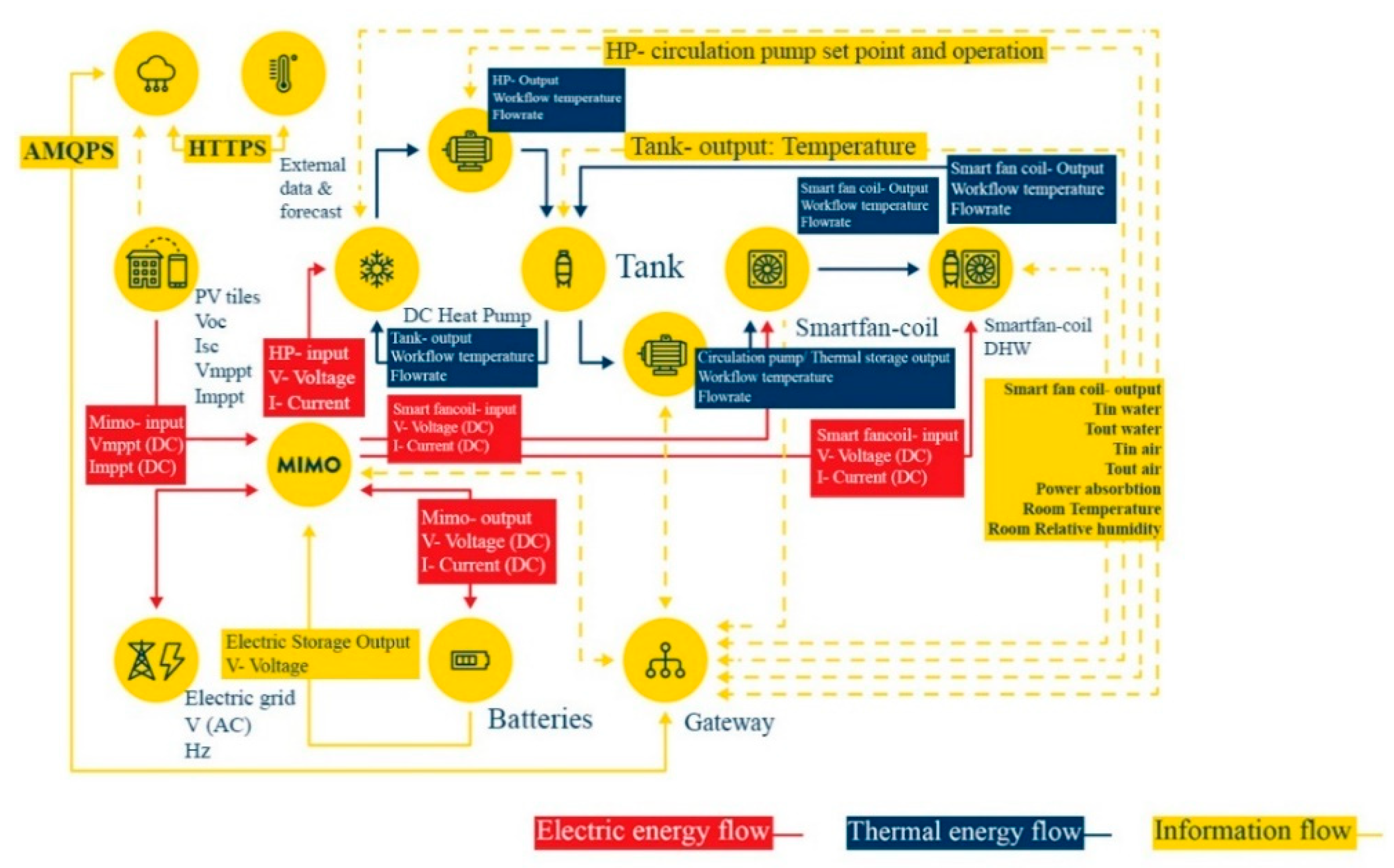
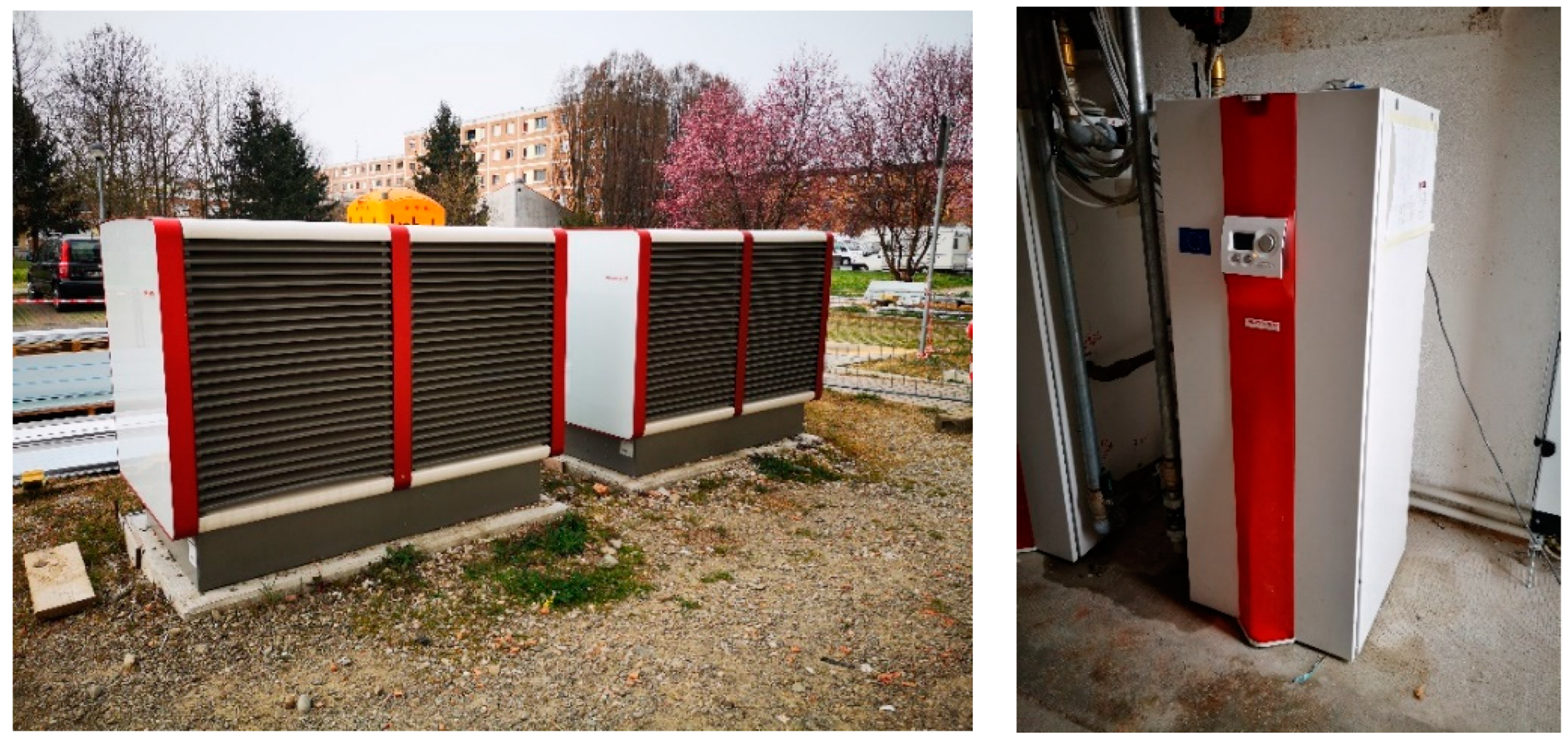
4. Description of the System Installed in the Case Study

The three main elements of the HVAC system are air-to-water heat pumps, thermal storage tanks, and smart fan coils (for every room instead of radiators), which together provide the desired comfort in the building.
The heat pumps (Figure 3), powered in DC, exchange heat with the environment by using heat from the ambient air to evaporate the liquid refrigerant in the outdoor unit. The two heat pumps, consisting of two outdoor units (air heat exchanger) and two indoor units (a condenser, compressor, control panel, and all connection components), are characterised by a heating and cooling capacity equal to 25 and 20 kW, respectively. The shape and material of the fins on the cover of the outdoor units have been optimised to reduce possible noise problems.
The operation of heat pumps with the BEMS includes:
  • Information exchange: The heat pump has an internal Modbus/TCP server that allows the operation of the equipment (i.e., operating modes, setpoint temperatures, etc.) and the retrieval of internal values.
  • Electricity management: The amount of electricity used to drive the heat pumps is managed by a multi-port power controller (MIMO) and taken from the PV system from a battery bank or the grid.
  • Sharing of thermal energy: The heat pump is connected to the heat storage tank [9].
The smart fan coil (Figure 4) is a component developed as a stand-alone water-to-air heat pump connected to a closed water loop system. The single unit, which was installed in each apartment, consisted of a hermetically sealed circuit of air and water, which could alternately act as a coolant. It also incorporated two heat exchangers that could act as either evaporators or condensers. An air-side heat exchanger adds or removes heat from the space by passing air through an internal coil, while a water-side heat exchanger adds or removes heat from the water loop. Of course, if the supply temperature of the water circuit was sufficient, the unit could also work as a conventional fan coil, thanks to the three suction fans installed above the heat exchanger [33].
The operation of smart fan coil units with the BEMS includes:
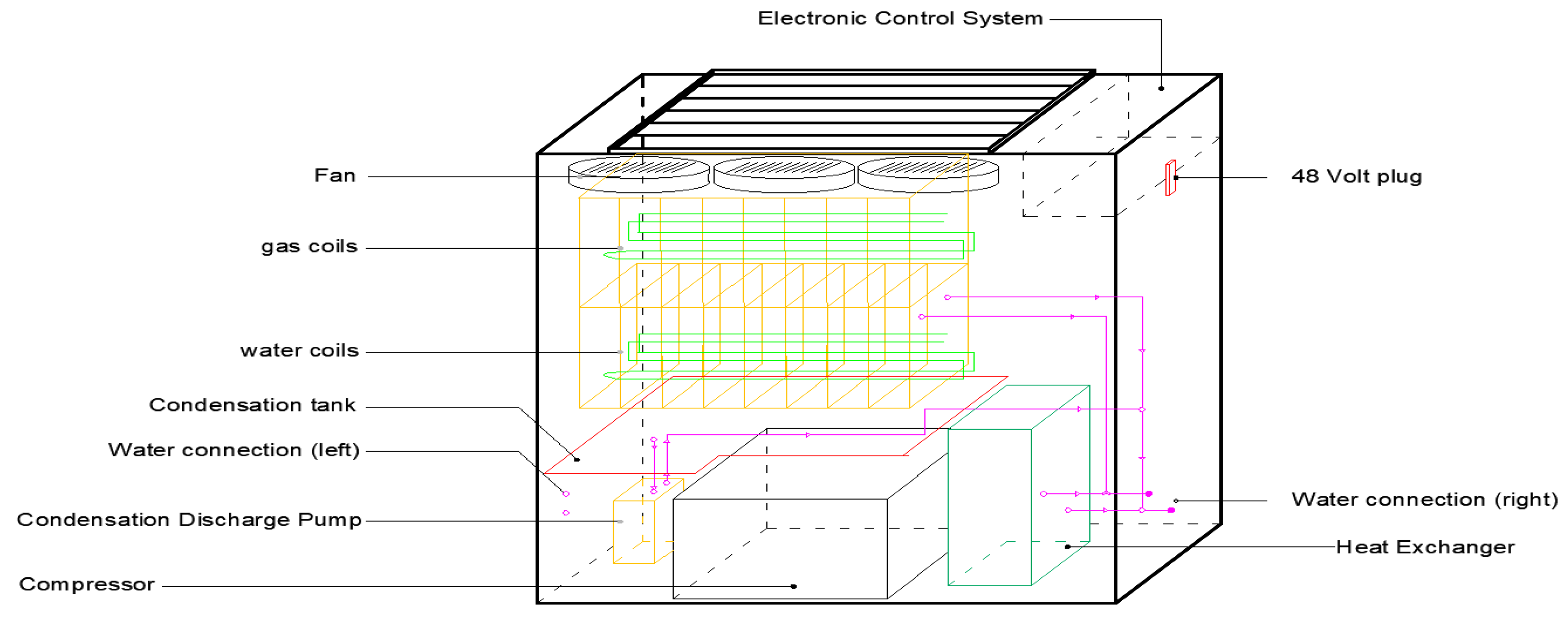
  • Information exchange: The smart fan coils send information (e.g., internal parameters, sensors, status) and receive information and commands from the building control system and gateway (e.g., on/off, set temperature).
  • Electricity supply: Smart fan coil units receive a 48 V DC power supply from the MIMO converter, which is taken from the PV system, from a battery bank or the grid.
  • Sharing of thermal energy: The smart fan coils are connected to the water loop and thus to the PCM tanks and the heat pumps.
The heat storage tanks (Figure 5) were selected separately for each case study.
As already introduced, to reduce the mismatch between energy production and consumption, three storage tanks with a total volume of 3000 L were selected for the Italian demo building. These were filled with PCM modules, which contributed to the storage of latent heat and water. The latter acted as a heat transfer medium and stored the rest of the sensible heat. The heat storage tanks were connected in series. The cooperation of the heat storage tanks with BEMS was ensured by a PLC (programmable logic controller), which ensured the implementation of special BEMS rules [10].
An inorganic chemical-based PCM, with a nominal freezing temperature of 24 °C and melting temperature of 25 °C, was selected due to its suitability for heating and cooling purposes. The material (savE® HS24) was encapsulated in spherical modules to avoid water contamination. Such a component stores thermal energy as latent heat in its crystalline form. On changing phase, this latent heat is released or absorbed, allowing the ambient temperature within the system to be maintained. The selected material ensured very efficient storage of heat and cold, even with limited volume and small temperature differences [34].
Characteristics of the selected material [35]:
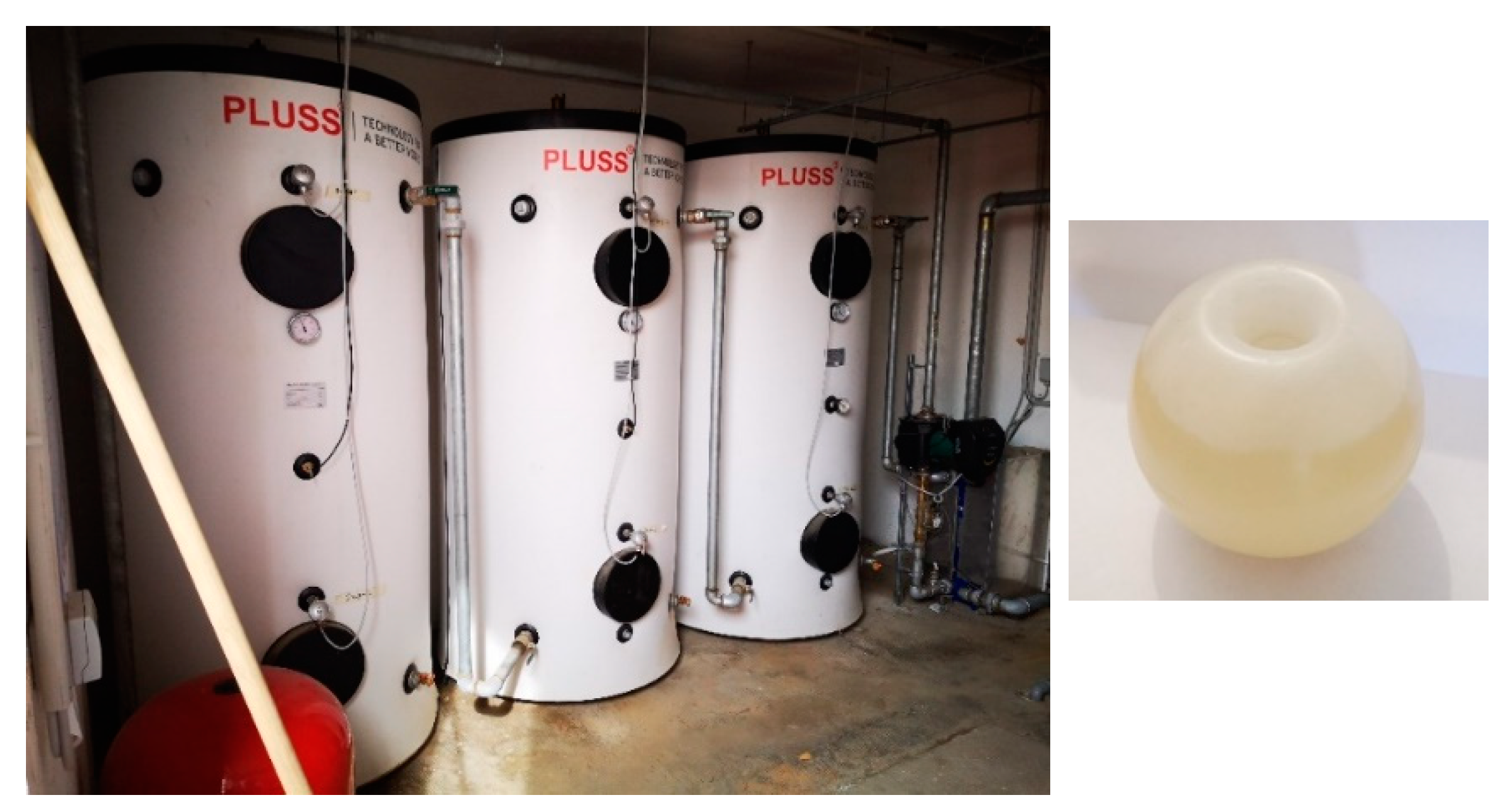
  • High thermal energy storage capacity (calculation of the stored thermal energy in a storage tank is shown in Appendix A);
  • Heat storage and release take place at relatively constant temperatures;
  • No supercooling effect, chemically inert;
  • Long-life product, with stable performance through the phase change cycles;
  • Easy to use;
  • Non-toxic.
The shape of the modules, which are polymer spheres about 70 mm wide (Figure 4), was designed so that the solidification/melting started from the inside and outside, thus avoiding a molten/solid core of the module [35].
The main properties of the selected storage tank and PCM are listed in Table 1 and presented in Figure 5.
With a nominal solidification temperature of 24 °C and a melting temperature of 25 °C, HS24 is a PCM based on inorganic chemicals. In its crystalline state, it stores thermal energy as latent heat. This latent heat is either emitted or absorbed at phase change, maintaining the system’s internal temperature. The proper proportion of several additives in HS24 enables equilibrium between the solid and liquid phases to be reached at the melting point.
A 20 g sample was extracted from the molten state and placed in a test tube. This information is evident from the T-History test graph (Figure 6). The test tube, along with a temperature-controlled bath, was utilised for the experiment. Both the test tube and the bath were equipped with temperature sensors, and a data logger was employed to log the temperature readings. Throughout the freezing and melting cycles, the temperature of the bath was consistently maintained at 45 °C.
Considering the temperature difference of 23 °C and 32 °C between the initial and final state, the stored heat of one storage tank is approximately 30 kWh, and for three storage tanks, this would be 90 kWh. If the storage tanks were only filled with water of the same volume and temperature difference, then the stored heat would reduce by roughly 60% and would amount to 11.5 kWh per storage tank. From this, we can conclude that for systems where we are limited by temperature difference and space, the use of storage tanks filled with PCMs is much more favourable than water storage tanks.

5. Experimental Results

A small-scale experimental test was conducted using a storage tank with a volume of 100 L. Within the tank, 31 L of PCM was encapsulated in spherical capsules. The PCM mixture consisted of an inorganic blend with a phase change occurring around 25 °C, occupying approximately 37% of the tank’s volume. The determination of PCM energy storage unit capacity follows the guidelines outlined in VDI 2164 (PCM energy storage systems in building services) and RAL-GZ 896 (RAL quality assurance of PCM). To simulate real-world conditions, the test set-up replicated the PCM, PCM objects, heat transfer fluid, and integration found in the actual application. Water temperature measurements were taken at three horizontally positioned points within the middle of the storage tank, as well as at the inlet and outlet. The measured results are depicted in the following figures.
The graphs in Figure 7 show the distribution of temperatures during the charge and discharge of the latent heat storage tank. In principle, it was a matter of measuring the accumulation capacity of the tanks. In the experiment, the important parameters were the inlet water temperature, the outlet water temperature, and the flow rate.
The graphs in Figure 8 show the flow of heat during the charging and discharging of the system. When charging the system, we can see that heat increases with time, but after about 2.5 h, it slowly stabilises. When discharging the system, we can see that the heat drops drastically.
During the entire cycle (Figure 9) of charging and discharging the storage tank, we can see the course of the temperature of the inlet and outlet water. The system was charged with an inlet water temperature of 24 °C and discharged with a temperature of 15 °C. A constant temperature for hot water was ensured with variable transformers. So, the operation of the heat storage tank can be described with several cycles.
From the results (Figure 10), we can see that the energy stored in a 100 L laboratory prototype tank with PCM is approximately 3 kWh. For three of them, this is 9 kWh. Therefore, we can conclude that the energy stored in a 1000 L real application tank is approximately 30 kWh and for three of them will be 90 kWh, which is in accordance with the calculated energy in melting/solidification heat calculated in Section 3.

6. Discussion

The implementation of advanced technologies in multi-apartment buildings can significantly enhance the efficiency of energy management systems, leading to increased energy savings and improved comfort levels. By incorporating heat storage systems with PCM modules into the water storage tanks, even greater benefits can be achieved. Based on preliminary calculations using PCM storage tanks in a laboratory setting, it has been observed that they possess a thermal capacity roughly three times higher than conventional water storage tanks. Similar results are reported in the numerical studies by Pagkalos et al. [36,37]. This demonstrates the potential of PCM-based systems to enhance thermal storage capabilities.
Moreover, the additional cost incurred for integrating PCM balls into the storage tanks is relatively affordable, with an approximate price of EUR 1.5 per ball, with the PCM price itself being in the range of 11 EUR/l [38]. This investment can deliver substantial returns in terms of energy efficiency, comfort, and financial aspects. The positive effect on the economical result is also reported by Chaiyat [38]. Their application involved the use of a PCM as part of the air-conditioning system in a form of a packed ball bed, and the payback time for the system was reported to be in the range of 4 to 5 years. Such a payback time is short and should be interesting for building owners and operators.
By harnessing the advantages of PCM-based heat storage systems, multi-apartment buildings can optimise energy usage, reduce carbon emissions, and provide a more comfortable living environment for occupants. Further research and development efforts in this field will be essential to refine and expand the application of PCM technologies, driving the widespread adoption of energy-efficient solutions in the built environment.

7. Conclusions

PCMs used for the storage of thermal energy as latent heat are an important class of modern materials that substantially contribute to the efficient use and conservation of solar energy. The storage of latent heat provides a greater density of energy storage with a smaller temperature difference between storing and releasing heat than the sensible heat storage method. PCM modules in water storage tanks increase thermal capacity by three times, leading to substantial energy savings. With a relatively affordable cost of implementation, it is a worthwhile investment for building owners. Further research in PCM technologies will drive the wider adoption of energy-efficient solutions, contributing to sustainable energy conservation.

Author Contributions

Writing—original draft, E.O., C.D.P., E.Z., F.L., N.A. and U.S. All authors have read and agreed to the published version of the manuscript.

Funding

European Commission, Funding from the European Union’s Horizon 2020 research and innovation programme under grant agreement N°768921.

Data Availability Statement

European Project HEART link to the project: https://heartproject.eu/.

Conflicts of Interest

The authors declare no conflict of interest.

Abbreviations

BEMSBuilding Energy Management System
BIPVBuilding Integrated Photovoltaics
COPCoefficient of Performance
CREATECompact Retrofit Advanced Thermal Energy Storage
DC-HPDirect Current Heat Pumps
DHWDomestic Hot Water
HEARTHolistic Energy and Architectural Retrofit Toolkit
HPHeat Pump
HVACHeating, Ventilation, and Air-Conditioning
IPCCPanel on Climate Change
MIMOMultiple Input–Multiple Output
NEBNew European Bauhaus
PBTESPacked Bed Thermal Energy Storage
PCMPhase-Change Material
PLCProgrammable Logic Controller
PVPhotovoltaics
SHIPSolar Heat Industrial Processes
TESThermal Energy Storage
TESSThermal Energy Storage System
TESSe2bAn integrated solution for residential building energy storage by solar and geothermal resources
THUMBS UPThermal energy storage solUtions to optimally Manage BuildingS and Unlock their grid balancing and flexibility Potential
UTESUnderground Thermal Energy Storage

Appendix A

Stored thermal energy in a storage tank is calculated using the following equation:
Q = Q w + Q P C M + Q H D P E
  • Q —total stored energy in a storage tank (kJ);
  • Q w —total stored energy in water (kJ);
  • Q P C M —total stored energy in PCM (kJ);
  • Q H D P E —total stored energy in HDPE (kJ).
Total stored energy in water is defined as:
Q w = m w c p , w T w
  • m w —mass of water in a storage tank (kg);
  • c p , w —specific heat of water (kJ/kgK);
  • T w —temperature difference of water between initial and final state (K).
Total stored energy in PCM is defined as:
Q P C M = m P C M h P C M
  • m P C M —mass of water in a storage tank (kg);
  • h P C M —enthalpy of PCM (kJ/kgK).
Total stored energy in HDPE is defined as:
Q H D P E = m H D P E c p , H D P E T H D P E
  • m H D P E —mass of HDPE in a storage tank (kg);
  • c p , H D P E —specific heat of HDPE (kJ/kgK);
  • T w , H D P E —temperature difference of HDPE between initial and final state (K).

References

  1. International Energy Agency (IEA). Buildings—Analysis; IEA: Paris, France, 2023. Available online: https://www.iea.org/reports/buildings (accessed on 27 April 2023).
  2. The Intergovernmental Panel on Climate Change. Sixth Assessment Report; IPCC: Geneva, Switzerland. Available online: https://www.ipcc.ch/assessment-report/ar6/ (accessed on 27 April 2023).
  3. Available online: https://heartproject.eu/wp-content/uploads/2021/08/D4.8-Final-BEMS-Hardware-Components.pdf (accessed on 26 October 2022).
  4. Carella, C. A First Look at REPowerEU: The European Commission’s Plan for Energy Independence from Russia; Florence School of Regulation: Florence, Italy, 2022; Available online: https://fsr.eui.eu/first-look-at-repowereu-eu-commission-plan-for-energy-independence-from-russia/ (accessed on 27 April 2023).
  5. Aste, N.; Pero, C.D.; Leonforte, F. Toward Building Sector Energy Transition. In Handbook of Energy Transitions; CRC Press: Boca Raton, FL, USA, 2022. [Google Scholar]
  6. Special Issue “Thermal Energy Storage in Building Integrated Thermal Systems”. Energies. Available online: https://www.mdpi.com/journal/energies/special_issues/building_integrated_thermal_system (accessed on 27 April 2023).
  7. Einstein. Available online: http://www.ectp.org/fileadmin/user_upload/documents/E2B/EINSTEIN/einstein-guidelines_stes-tanks-del-38.pdf (accessed on 27 April 2023).
  8. Compact REtrofit Advanced Thermal Energy Storage|CREATE Project|Fact Sheet|H2020|CORDIS|European Commission. Available online: https://cordis.europa.eu/project/id/680450 (accessed on 27 April 2023).
  9. Thermal Energy Storage Systems for Energy Efficient Buildings. An Integrated Solution for Residential Building Energy Storage by Solar and Geothermal Resources|TESSe2b Project|Fact Sheet|H2020|CORDIS|European Commission. Available online: https://cordis.europa.eu/project/id/680555/it (accessed on 27 April 2023).
  10. High-Capacity and High-Performance Thermal Energy Storage Capsule for Low-Carbon and Energy Efficient Heating and Cooling Systems|Hi-ThermCap Project|Fact Sheet|H2020|CORDIS|European Commission. Available online: https://cordis.europa.eu/project/id/778788 (accessed on 27 April 2023).
  11. Thermal Energy Storage solutions to Optimally Manage Buildings and Unlock Their Grid Balancing and Flexibility Potential. Available online: https://cordis.europa.eu/project/id/101096921 (accessed on 27 April 2023).
  12. New European Bauhaus: Beautiful, Sustainable, Together. Available online: https://new-european-bauhaus.europa.eu/index_en (accessed on 27 April 2023).
  13. Available online: https://heartproject.eu/wp-content/uploads/2021/08/D1.1-Project-management-and-quality-Plan.pdf (accessed on 26 October 2022).
  14. Parameshwaran, R.; Kalaiselvam, S.; Harikrishnan, S.; Elayaperumal, A. Sustainable thermal energy storage technologies for buildings: A review. Renew. Sustain. Energy Rev. 2012, 16, 2394–2433. [Google Scholar] [CrossRef]
  15. Najafian, A.; Haghighat, F.; Moreau, A. Integration of PCM in domestic hot water tanks: Optimization for shifting peak demand. Energy Build. 2015, 106, 59–64. [Google Scholar] [CrossRef]
  16. Zanetti, E.; Scoccia, R.; Aprile, M.; Motta, M.; Mazzarella, L.; Zaglio, M.; Pluta, J. Building hvac retrofitting using a pv assisted dc heat pump coupled with a pcm heat battery and optimal control algorithm. E3S Web Conf. 2019, 111, 04041. [Google Scholar] [CrossRef]
  17. Xu, T.; Chiu, J.N.; Palm, B.; Sawalha, S. Experimental investigation on cylindrically macro-encapsulated latent heat storage for space heating applications. Energy Convers. Manag. 2019, 182, 166–177. [Google Scholar] [CrossRef]
  18. Kutlu, C.; Zhang, Y.; Elmer, T.; Su, Y.; Riffat, S. A simulation study on performance improvement of solar assisted heat pump hot water system by novel controllable crystallization of supercooled PCMs. Renew. Energy 2020, 152, 601–612. [Google Scholar] [CrossRef]
  19. Huang, H.; Xiao, Y.; Lin, J.; Zhou, T.; Liu, Y.; Zhao, Q. Improvement of the efficiency of solar thermal energy storage systems by cascading a PCM unit with a water tank. J. Clean. Prod. 2020, 245, 118864. [Google Scholar] [CrossRef]
  20. Kocak, B.; Paksoy, H. Performance of laboratory scale packed-bed thermal energy storage using new demolition waste based sensible heat materials for industrial solar applications. Sol. Energy 2020, 211, 1335–1346. [Google Scholar] [CrossRef]
  21. Liu, Y.; Wang, N.; Ding, Y. Preparation and properties of composite phase change material based on solar heat storage system. J. Energy Storage 2021, 40, 102805. [Google Scholar] [CrossRef]
  22. Ali, H.M. Phase change materials based thermal energy storage for solar energy systems. J. Build. Eng. 2022, 56, 104731. [Google Scholar] [CrossRef]
  23. Munir, Z.; Roman, F.; Niazi, B.M.K.; Mahmood, N.; Munir, A.; Hensel, O. Thermal analysis of a solar latent heat storage system using Scheffler concentrator for agricultural applications. Appl. Therm. Eng. 2023, 218, 119230. [Google Scholar] [CrossRef]
  24. Atalay, H. Assessment of energy and cost analysis of packed bed and phase change material thermal energy storage systems for the solar energy-assisted drying process. Sol. Energy 2020, 198, 124–138. [Google Scholar] [CrossRef]
  25. Reyes, A.; Mahn, A.; Vásquez, F. Mushrooms dehydration in a hybrid-solar dryer, using a phase change material. Energy Convers. Manag. 2014, 83, 241–248. [Google Scholar] [CrossRef]
  26. Du, K.; Calautit, J.; Eames, P.; Wu, Y. A state-of-the-art review of the application of phase change materials (PCM) in Mobilized-Thermal Energy Storage (M-TES) for recovering low-temperature industrial waste heat (IWH) for distributed heat supply. Renew. Energy 2021, 168, 1040–1057. [Google Scholar] [CrossRef]
  27. Xia, L.; Liu, R.; Zeng, Y.; Zhou, P.; Liu, J.; Cao, X.; Xiang, S. A review of low-temperature heat recovery technologies for industry processes. Chin. J. Chem. Eng. 2019, 27, 2227–2237. [Google Scholar] [CrossRef]
  28. Zauner, C.; Windholz, B.; Lauermann, M.; Drexler-Schmid, G.; Leitgeb, T. Development of an Energy Efficient Extrusion Factory employing a latent heat storage and a high temperature heat pump. Appl. Energy 2020, 259, 114114. [Google Scholar] [CrossRef]
  29. Gu, Z.; Liu, H.; Li, Y. Thermal energy recovery of air conditioning system—Heat recovery system calculation and phase change materials development. Appl. Therm. Eng. 2004, 24, 2511–2526. [Google Scholar] [CrossRef]
  30. Oró, E.; Miró, L.; Farid, M.M.; Martin, V.; Cabeza, L.F. Energy management and CO2 mitigation using phase change materials (PCM) for thermal energy storage (TES) in cold storage and transport. Int. J. Refrig. 2014, 42, 26–35. [Google Scholar] [CrossRef]
  31. Oro, E.; de Gracia, A.; Castell, A.; Farid, M.M.; Cabeza, L.F. Review on phase change materials (PCMs) for cold thermal energy storage applications. Appl. Energy 2012, 99, 513–533. [Google Scholar] [CrossRef]
  32. Available online: https://heartproject.eu/wp-content/uploads/2021/08/D2.1-Application-context-periodic-update-I.pdf (accessed on 26 October 2022).
  33. Available online: https://heartproject.eu/wp-content/uploads/2021/08/D6.5-DC-HP-units-thermal-storage-units-and-smart-fan-coils-for-on-field-demonstration-II.pdf (accessed on 26 October 2022).
  34. Available online: https://pluss.co.in/wp-content/uploads/2022/03/Doc-075_PCM_HS24_TDS.pdf (accessed on 11 June 2023).
  35. Available online: https://www.pluss.co.in/upload/technical-datasheets/2019/Doc%20303%20TDS_HS%2024.pdf (accessed on 26 October 2022).
  36. Pagkalos, C.; Dogkas, G.; Koukou, M.K.; Konstantaras, J.; Lymperis, K.; Vrachopoulos, M.G. Evaluation of water and paraffin PCM as storage media for use in thermal energy storage applications: A numerical approach. Int. J. Thermofluids 2020, 1–2, 100006. [Google Scholar] [CrossRef]
  37. Pagkalos, C.; Michail, V.; Konstantaras, J.; Lymperis, K. Comparing water and paraffin PCM as storage mediums for thermal energy storage applications. E3S Web Conf. 2019, 116, 00057. [Google Scholar] [CrossRef]
  38. Chaiyat, N. Energy and economic analysis of a building air-conditioner with a phase change material (PCM). Energy Convers. Manag. 2015, 94, 150–158. [Google Scholar] [CrossRef]
Figure 1. Building in Italy (Bagnolo in Piano).
Energies 16 06127 g001
Figure 2. BEMS elements and connections between them [9]. The functional flow chart, where the main thermal energy, electricity, and information flows are identified, represents the basic tool to carefully assess all of the interactions among the subcomponents. In this sense, all of the input/output parameters of the elements directly interacting with each other are shown.
Energies 16 06127 g002
Figure 3. Outdoor and one of the indoor heat pump units.
Energies 16 06127 g003
Figure 4. Smart fan coil.
Energies 16 06127 g004
Figure 5. Heat storage tanks (3 × 1000 L) and a PCM module.
Energies 16 06127 g005
Figure 6. PCM module T-history and enthalpy distribution of a PCM [35].
Energies 16 06127 g006
Figure 7. Heat charge (left) and discharge (right) of latent thermal storage tank—temperature distribution.
Energies 16 06127 g007
Figure 8. Charged (left) and discharged (right) heat of latent thermal storage tank—released heat.
Energies 16 06127 g008
Figure 9. One thermal storage cycle.
Energies 16 06127 g009
Figure 10. Thermal power (left), heat charge and discharge curve (right).
Energies 16 06127 g010
Table 1. Important information about the selected PCM [35].
Storage Tank (One Unit)
Size (Ø × height) (mm):Ø950 × 2120 mm
Weight (kg):250 kg (empty) + 425 kg (PCM modules)
PCM Module (One Module)
Size (Ø) (mm):Ø 75
Weight (g):262
Plastic HDPE (high-density polyethylene):42 g (1 empty module)
Salt hydrate mixture:220 g (in 1 module)
PCM Specifications
Melting/solidification temperature (°C):26/25
Specific heat (solid/liquid) (kJ/kJK):2.07/2.42
Heat conduction (solid/liquid) (W/mK):1.05/0.55
Density (solid/liquid) (kg/m3):1621/1510
Enthalpy per mass (kJ/kg):199
Enthalpy per litre (kJ/L):300
Water capacity (litres):1000 (60% water + 40% PCM)
Maximum charge thermal power (heating mode/cooling mode) (kW):50/40
Maximum discharge thermal power (heating mode/cooling mode) (kW):15 (ΔT = 35–25 °C (Treturn = 15 °C), 1 kg/s, mixing valve outlet 25 °C)
Disclaimer/Publisher’s Note: The statements, opinions and data contained in all publications are solely those of the individual author(s) and contributor(s) and not of MDPI and/or the editor(s). MDPI and/or the editor(s) disclaim responsibility for any injury to people or property resulting from any ideas, methods, instructions or products referred to in the content.

