Article

Li3PO4-Coated Graphite Anode for Thermo-Electrochemically Stable Lithium-Ion Batteries

1
Department of Chemistry and Chemical Institute for Functional Materials, Pusan National University, Busan 46241, Republic of Korea
2
Department of Energy Science and Engineering, Daegu Gyeongbuk Institute of Science & Technology (DGIST), Daegu 42988, Republic of Korea
3
Department of Chemistry, The University of North Carolina at Charlotte, Charlotte, NC 28223, USA
*
Author to whom correspondence should be addressed.
Energies 2023, 16(17), 6141; https://doi.org/10.3390/en16176141
Submission received: 30 May 2023 / Revised: 10 August 2023 / Accepted: 18 August 2023 / Published: 23 August 2023
(This article belongs to the Section D2: Electrochem: Batteries, Fuel Cells, Capacitors)

Abstract

:
Extensive research on electrode materials has been sparked by the rising demand for high-energy-density rechargeable lithium-ion batteries (LIBs). Graphite is a crucial component of LIB anodes, as more than 90% of the commercialized cathodes are coupled with the graphite anode. For the advanced graphite anode, the fast charge–discharge electrochemical performance and the thermal stability need to be further improved in order to meet the growing demand. Herein, a graphite anode material’s thermo-electrochemical stability was improved by the surface coating of lithium phosphate (Li3PO4; LPO). The graphite anode with a well-dispersed LPO-coating layer (graphite@LPO) demonstrated significant improvement in the cycle and rate performances. The graphite@LPO sample showed a capacity retention of 67.8% after 300 cycles at 60 °C, whereas the pristine graphite anode failed after 225 cycles, confirming the ameliorated thermo-electrochemical stability and cyclability by LPO coating. The improved thermo-electrochemical stability of the graphite@LPO anode was validated by the full-cell tests as well. The performance enhancement by LPO-coating is due to the suppression of the growth of the surface film and charge-transfer resistances during the repeated cycling, as evidenced by the electrochemical impedance spectroscopy analysis.

1. Introduction

Lithium-ion batteries (LIBs) have grown as the major energy storage solution for a wide variety of applications such as electronic devices, electric vehicles (EV), hybrid electric vehicles (HEV), and energy storage systems (ESS) [1,2,3,4,5,6,7]. However, in order to satisfy the increased demand for LIBs, the higher energy density and capacity of LIBs are required, requiring research of advanced anode materials with lower cost, extended cycle life, and enhanced safety [6,7,8,9]. Graphite has been demonstrated to be such an ideally practical anode that made the successful operation of LIBs possible. Since the commercialization of LIBs, graphite has dominated the market for anodes with more than 95% of the market share. This is because graphite possesses a unique combination of lower cost, abundance, enhanced power density, and longer cycle life [5,9,10,11,12,13].
Although many high capacity anode candidates based on lithium metal, sulfides, and oxides have been studied over the past 20 years, few of them exhibit overall competitive performances. Li metal has been considered as a “Holy Grail” anode due to the ultrahigh specific capacity; however, the interfacial instability and dendritic growth of lithium deposits have severely impeded the practical deployment [1,6,14]. Beside Li metal, insertion-type lithium titanate (Li4Ti5O12; LTO), conversion-type metal oxides, and alloying-type metal anodes have drawn much attention [15,16,17]. However, LTO’s high potential (~1.55 V vs. Li/Li+) has limited the application to some fast-charging devices such as stylus pens [9,14]. On the other hand, the problem of Si and metal alloys’ severe volume expansion during the cycling is yet to be solved [3,11].
Although graphite is currently the dominant anode material for the LIB market, its electrochemical performance and thermal stability at high temperature must be substantially improved to meet the growing demand for advanced LIBs for electric vehicles and grid-scale energy storage facilities. There are two types of graphite: natural graphite and synthetic graphite. Natural graphite exhibits a high capacity of around 372 mAh/g, which is equivalent to the theoretical value; however, the highly anisotropic nature often leads to quite an extensive volume change that is prone to deteriorate the conductive channels of the electrode. On the other hand, artificial graphite’s capacity is usually lower (~350 mAh/g), but it can be tuned by varying the quantity of the amorphous phase on the surface [18,19,20,21]. Artificial graphite exhibits a longer cycle life because the overall volume change is less severe during the reaction of Li+ ion (de)intercalation, due to more isotropic structures compared to the natural graphite [1,12,20]. In addition, there has been increased interest in practices that avoid the growth of lithium dendrites upon fast charging by surface engineering of graphite [22,23,24].
There have been numerous attempts reported to increase the stability of the cathode active materials at high temperatures, including a coating on the particles or doping between layers of layered structure [25,26,27,28,29,30]. Particularly, in the case of surface coating, the series of traditional metal oxides like TiO2, ZrO2, and SiO2 have been introduced as coating agents to enhance the performance of the LIB cathode active materials at high temperature and voltage. However, the series of metal oxides also caused increased resistance and poor rate capability. Among various coating agents, metal phosphates have been promising candidates to enhance the cathode active materials’ performances at high voltage and temperatures. For metal phosphate-based coating materials, the chemical bond between polyanion (PO43−) and metal cation has a strong covalent property, which suppresses the reactions that can occur between the electrode and the electrolyte. The following factors led to the selection of PO43− as the coating substance. (1) Phosphates such as FePO4, AlPO4, and Ni3(PO4)2 [31,32,33,34], Co3(PO4)2 [35,36], and FePO4 [37,38,39] have been used to coat the surface of cathode particles, improving the electrochemical performances of the active materials. (2) The method is a straightforward replacement reaction that can deposit phosphates on the surface of active material. (3) Phosphates have been investigated as a viable barrier coating due to its high phase stability, acceptable coefficient of thermal expansion, and good environmental endurance [31,32,33,34,35,37,38,40,41,42]. (4) Most importantly, the artificial protection layer of phosphates can scavenge HF in Li-ion batteries [38,43,44].
In this paper, we utilize Li3PO4 as the coating material of graphite due to the protection functionality and the significant ionic conductivity, which can lead to the improved cycle performance both at room and elevated temperatures [43,45,46,47,48,49,50,51]. The electrochemical and physiochemical tests reveal that the thermal stability of the graphite anode is significantly improved by Li3PO4 coating due to the suppression of interfacial side reactions with an organic electrolyte. The suggested coating strategy renews the prospects of a graphite anode that functions safely at the high-temperature operation of LIBs.

2. Experimental

2.1. LPO Coating on the Particle of Graphite

Lithium nitrate (LiNO3, 98%) and ammonium dihydrogen phosphate (NH4H2PO4, 98%) were purchased from Daejung corporation. The overall process of coating is shown in Figure 1a. A sol-gel method was employed for LPO coating on the particles of graphite. The LiNO3 and NH4H2PO4 were added in a molar ratio of 3:1 into 50 mL of isopropyl alcohol (IPA, Daejung Co., Republic of Korea, 99.7%) solvent and stirred for 12 h at 25 °C. The artificial graphite powder (FSNC-4; Ningbo Shanshan Co., China) was added and stirred for 12 h. The composition of LPO was controlled as 2 wt.% of LPO and 98 wt.% of graphite. The mixed solution was filtered out using a vacuum pump and dried at 110 °C under vacuum for 12 h. Finally, it was heated in a furnace at 400 °C for 4 h after grinding it to obtain the desired product.

2.2. Preparation of Electrode and Coin Cell Assembly

Slurry was made using pristine graphite and graphite@LPO powder samples as the active material, carbon black (Super-P; Timcal Co. Switzerland) as a conductive agent, and polyvinyl fluoride (PVdF, KF9700, Kureha Co., Japan) as a binder mixed in the ratio of 90:5:5 wt.% using N–methyl pyrrolidone (NMP, Sigma Aldrich Co., USA, 99.5%) as the solvent. The slurry was coated onto a copper foil current collector and dried at 80 °C under vacuum for 2 h. The thickness of each dried electrode sample was controlled using a roll press, and the electrodes were punched out in circular shapes having a diameter of 14 mm with a loading of 2.0 mg cm−2. These electrodes were placed as the working electrode. Lithium foil was used as the counter electrode with a diameter of ca. 16 mm. Then, 2032-type coin cells were assembled in an Argon-filled glovebox (MOTEK Co., Republic of Korea). A porous polyethylene film (Separator-2400; 25 μm thick; Celgard Co., USA) was used as a separator, and 1 M lithium hexafluorophosphate (LiPF6) dissolved in a mixed solvent of ethylene carbonate (EC) and ethyl methyl carbonate (EMC) (3:7 (w/w) ratio; Panax-Etec Co., Republic of Korea) was used as the electrolyte for assembling the coin cell. The Li|graphite cells were cycled at current densities in the unit of C-rate (1C = 372 mA g−1) in a potential range of 0.05~2.0 V vs. Li/Li+. Full cells were assembled using LiCoO2 (LCO; MTI Korea Co., Republic of Korea) as the cathode and the graphite electrodes as the anode with the areal capacity of about 1 mAh cm−2. Capacity ratio of negative to positive electrodes (NP ratio) of the full cells was set to about 1.08. The 1C rate corresponded to approximately 1 mA cm−2. The assembled graphite|LCO cells were cycled at 0.2C in a voltage range of 2.5~4.3 V.

2.3. Analysis and Electrochemical Characterizations

The morphology of LPO-coated graphite particles was analyzed using scanning electron microscopy (SEM; SUPRA40; Hitachi Co., Japan). Carbon, phosphorus, and oxygen in the powder were detected by energy-dispersive spectroscopy installed in the SEM. Transmission electron microscopy (TEM; Tecnai G2 F20 TWIN TMP; FEI Co., USA) was measured to verify the coating of LPO on graphite. X-ray diffraction (XRD; MiniFlex600; Rigaku Co., Japan) was employed to analyze the crystal structure of the powder samples. Raman spectroscopy (Nicolet Almega XR; Thermo Scientific Co., USA) was used for the information on chemical bonding. The thermogravimetric analyzer (TGA; TG-DTA2000SA; Bruker Co., USA) was conducted to confirm the Li3PO4. The coin-type cells made of pristine and LPO-coated graphite were cycled using a battery cycler (WBC3000Le32; WonA Tech Co., Republic of Korea) in a temperature chamber. The potentiostat (VMP3, Bio-Logic Co., France) was used to measure the electrochemical impedance spectroscopy of the cells in the range from 200 kHz to 5 mHz at 25 °C.

3. Results and Discussion

SEM imaging was performed to confirm the coating of LPO on graphite (Figure 1b), together with the elemental mapping using EDS (energy-dispersive spectroscopy). Phosphorus and oxygen are well-dispersed in the SEM-EDS images (Figure 1c–e). The EDS profile in Figure S1 indicates that there is no impurity peak such as nitrogen from by-products such as NH4 or NO3. In addition, the TEM image of graphite@LPO (Figure 1f) verifies that Li3PO4 of ca. 10.6 nm coats the surface of the cathode, whereas the pristine graphite does not possess any coating layer (Figure S2).
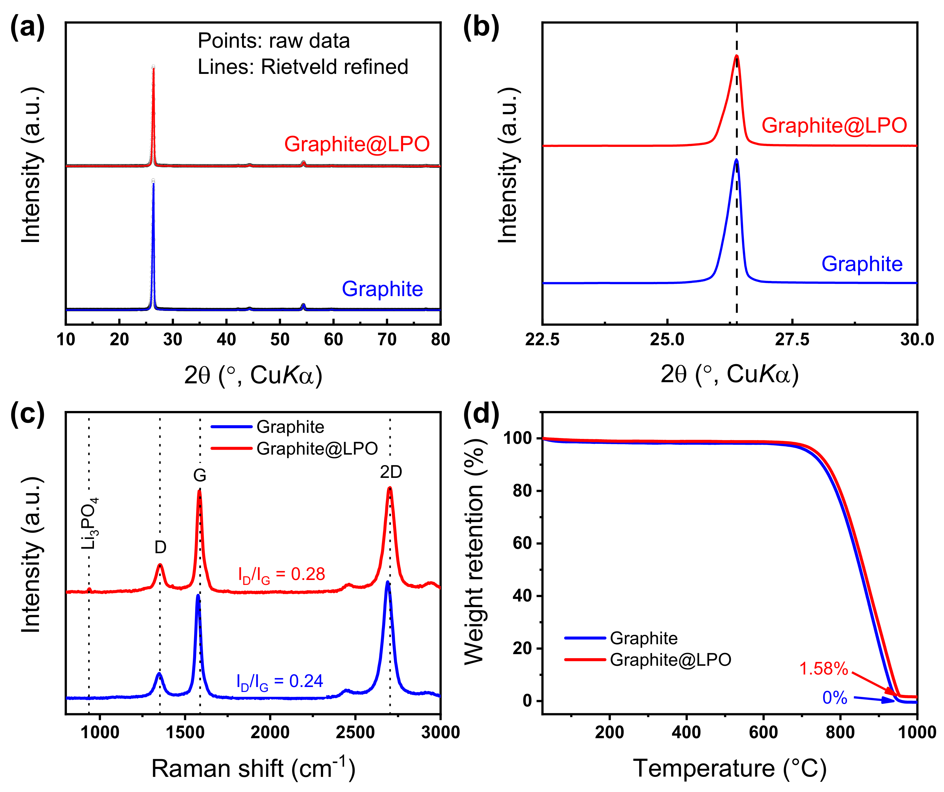
To study the difference between the samples of the pristine and coated graphite powders, the samples’ XRD patterns were measured and analyzed by Rietveld refinement. The XRD patterns in Figure 2 confirm the equivalent graphite structure of hexagonal layered structure (P61mmc, Table S1) [52], without any other noticeable impurity. The relatively small amount of coating agent was hardly detectable in the XRD pattern; this is in accordance with Song et al.’s report that the LPO-coating layer exhibits an amorphous phase at 400 °C [43].
Raman spectroscopy is one of the useful methods to observe carbon’s defects, microstructure, and crystallinity. As shown in Figure 2c, the two characteristic peaks are observed at 1352 and 1586 cm−1 in both samples, which correspond to the D and G bands, respectively, with an additional peak at around 2700 cm−1 that corresponds to the 2D band. The intensity ratio of ID/IG of graphite and graphite@LPO were 0.24 and 0.28, respectively, implying an insignificant level of structural defect formation during the coating process. In addition, the weak LPO peak on graphite@LPO is shown at nearby 940 cm−1 (Figure S3). Thermogravimetric analysis (TGA) was conducted to determine the quantitative mass percentage of Li3PO4 in graphite@LPO (Figure 2d and Figure S4). The graphite powder retains almost 0% mass at 1000 °C by the combustion; on the other hand, the graphite@LPO exhibits a retention of 1.58 wt.%, which indicates the amount of LPO in the coated sample.
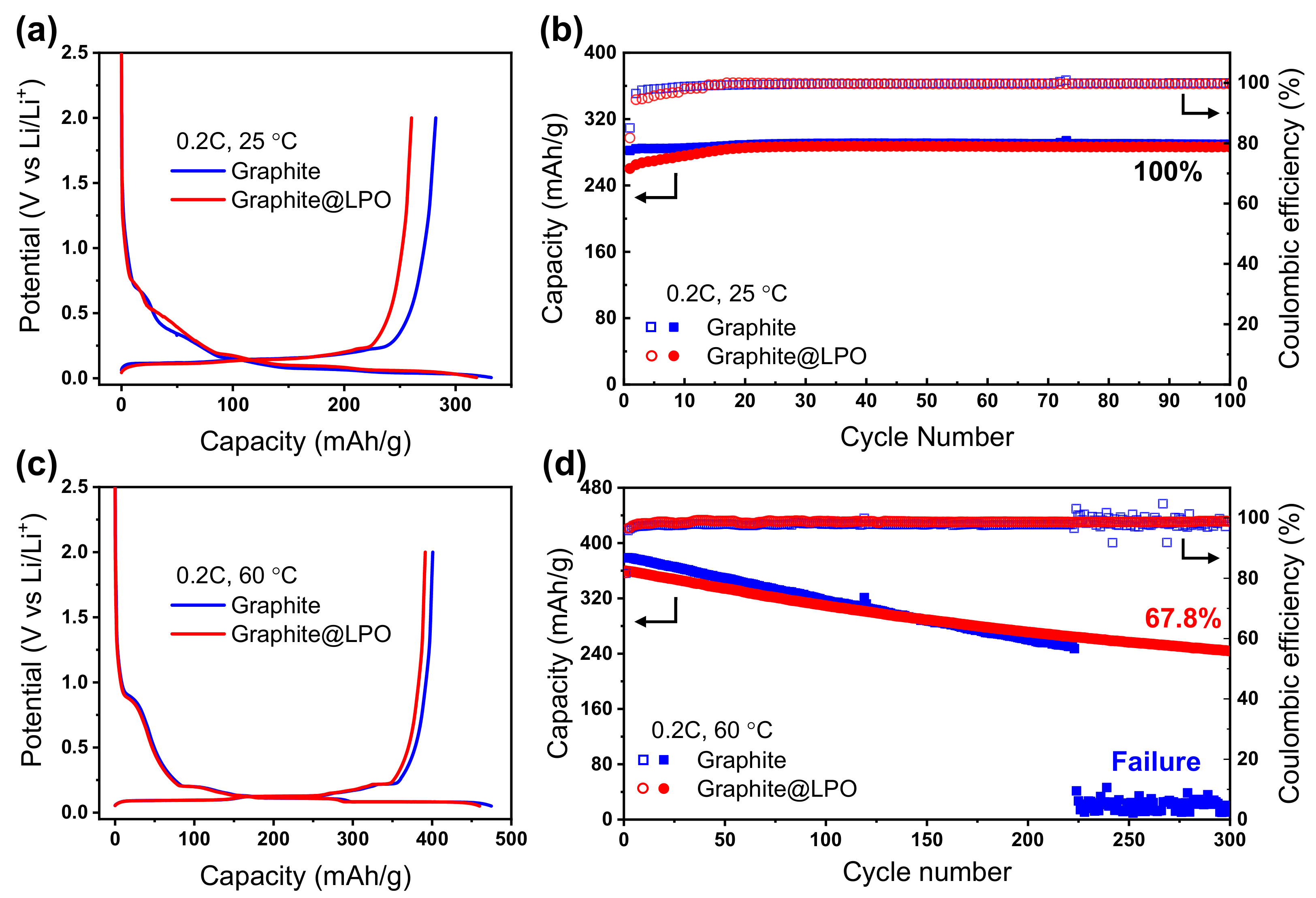
The rate capability test was examined using the two cells to study the effects of LPO on the rate performance. As shown in Figure S5a, a lower delithiation capacity of the graphite@LPO cell is found at 0.1C compared to the pristine graphite one. However, the degree of reduced delithiation capacity of the two cells dwindles gradually as the C-rate increases, and exceptionally, the capacity of the graphite@LPO cell slightly outperforms the pristine one over the 1 C-rate. Figure S5b shows the detailed normalized capacity retention of both samples following each C-rate. To understand the tendency of overpotential, the cell of cyclic voltammetry (CV) of the samples was measured at each scan rate (Figure S5c,d). The highest points of the anodic peaks for pristine graphite and graphite@LPO cells are located nearby 0.38 and 0.35 V at 1 mV s−1, 0.47 and 0.42 V at 5 mV s−1, and 0.76 and 0.67 V at 25 mV s−1. This result reveals the lower overpotential of the graphite@LPO over the pristine graphite anode. Figure 3 represents the electrochemical properties of the graphite|Li half cells. The initial delithiation capacity values of pristine and graphite@LPO are estimated to be 282.2 and 260.4 mAh g−1 at 0.2C (Figure 3a). Cycling stability of the pristine graphite and graphite@LPO cells at 25 °C is presented in Figure 3b. In the initial cycling, the charging capacity of the graphite@LPO cell is slightly less than the pristine graphite, and the capacity retention of both cells is approximately 100% for 100 cycles. In fact, the initial capacity of LPO-coated graphite is always smaller than the pristine graphite, regardless of the temperature. This will be related to the larger film resistance due to the electronically insulating nature of LPO.
Figure 3c,d display the electrochemical properties of the cells at 60 °C. There have been previous studies that report cell-test results at 60 °C in the electrolyte of 1 M LiPF6 in EC:EMC, despite the fact that the flammable liquid electrolyte can be evaporated at that temperature [53,54,55]. Therefore, we utilized the high-temperature operation as a platform for the accelerated test of the cycling stability of the electrodes, as the side reactions become more evident at the raised temperature. As shown in Figure 3c, the initial delithiation capacity values at 0.2C for pristine graphite and graphite@LPO are 400.9 and 391.2 mAh g−1, respectively. The cycle performances at 60 °C exhibit deteriorated cycling stability for both samples, opposite to the stable cycling at 25 °C (Figure 3d). Especially, the pristine graphite cell exhibits a lower capacity retention of 66.2% during 220 cycles; and the cell failed abruptly after 225 cycles. On the other hand, the capacity of LPO-coated graphite was constantly maintained up to 73.7% and 67.8% at the 220th and 300th cycles, respectively. In comparison, a polydopamine-coated graphite anode retained 56.9% of the initial capacity after 100 cycles under the equivalent condition of 60 °C [53]. Moreover, the graphite@LPO reveals a higher average coulombic efficiency of 98.5% than the pristine graphite one (97.7%). The cells were analyzed through CV following cycle stability at 60 °C. The pristine graphite reserved 86.61% capacity at the 50th cycle compared to the 2nd cycle. On the other hand, the LPO-coated graphite maintained 95.60% capacity (Figure S6). This observation supports the improved thermo-electrochemical stability compared to the pristine one.
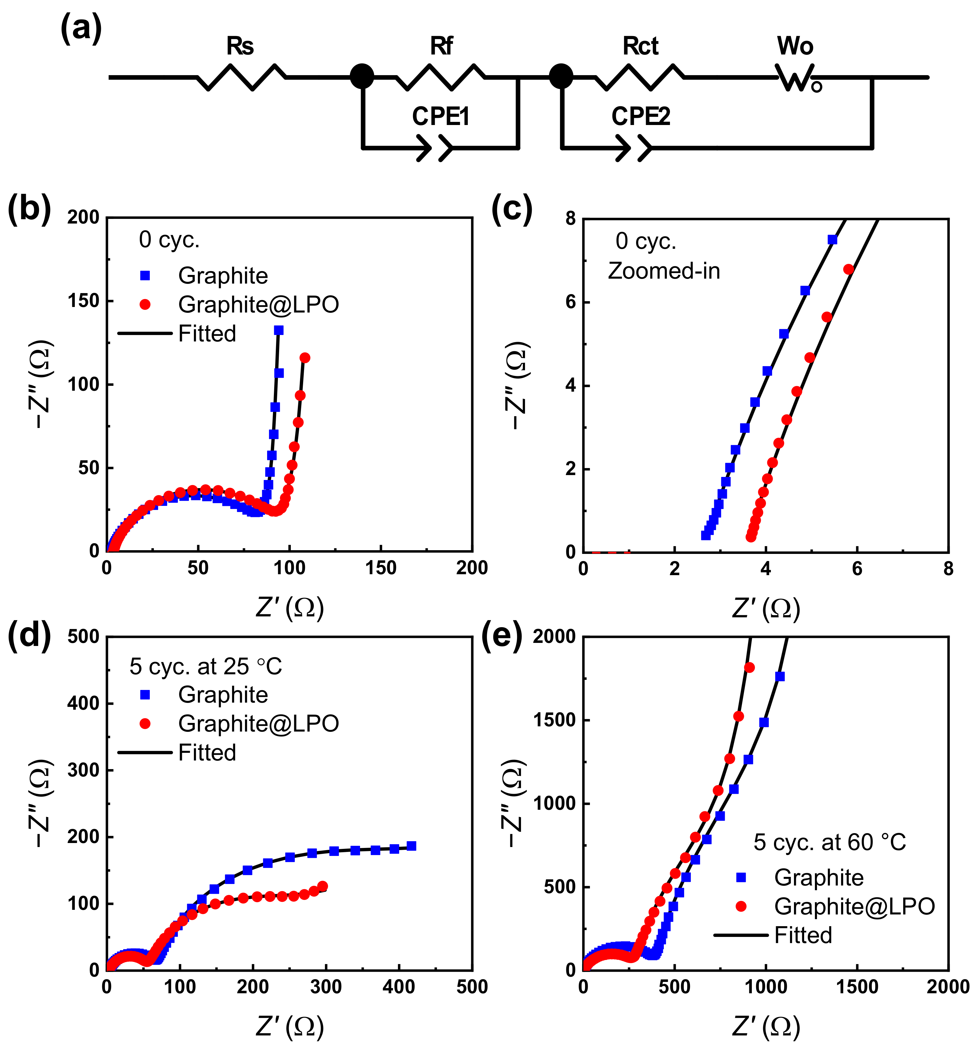
EIS was performed to analyze the reasons for the enhanced electrochemical performances of LPO for Li|graphite cells [56]. In general, there are three components of resistance in the impedance for LIBs: ohmic resistance (Rohm) that is mostly the resistance of the electrolyte, the film resistance (Rf) that is attributed to the resistance of solid electrolyte interphase (SEI), and charge transfer resistance (Rct) that is related with the charge transfer polarization. The slope following the semi-circles is attributed to the Warburg impedance at a lower frequency, owing to the ionic diffusion. All Nyquist plots were fitted using the equivalent circuit presented in Figure 4a. Before cycling, the diameter of the semi-circles (Rf + Rct) of the coated graphite cell (98.3 Ω) was slightly larger than the pristine one (90.5) (Figure 4b). The zoomed-in view shows Rohm of the pristine graphite and graphite@LPO cells are 2.6 and 3.5 Ω, respectively (Figure 4c). The larger resistance values of the LPO-coated graphite may be due to the LPO coating layer. After five cycles at 25 °C, the film resistance (Rf) of the LPO-coated graphite (57.5 Ω) was smaller than that of the pristine graphite (69.5 Ω); and the charge transfer resistance (Rct) of the LPO-coated graphite (210 Ω) was also smaller than that of the pristine graphite (350 Ω), as shown in Figure 4d. It is noted that the EIS spectra in Figure 4d do not vividly represent the usual Warburg diffusion element with the slope of 45°; those phenomena happen when the diffusion is deeply correlated with the charge transfer reaction, resulting in the suppressed semi-circles as shown in the low frequency region of Figure 4d. After five cycles at 60 °C, the Rf and Rct resistance values of the graphite@LPO cell (Rf = 287 Ω; Rct = 570 Ω) were remarkably smaller than for the pristine one (Rf = 401 Ω; Rct = 750 Ω) (Figure 4e). These results suggest that the LPO-coating mitigates the electrolyte decomposition that generates thicker solid-electrolyte interphase upon cycling. As future work, a more detailed analysis of the surface film will benefit from fine-tuning the LPO-coated graphite anode, for example, using extreme high-resolution SEM under a low acceleration voltage [57].
For further evaluation of the pristine graphite and graphite@LPO cells, full cells were assembled using LiCoO2 (LCO) as the cathode. Similar voltage profiles of LCO|graphite full cells were observed at 25 °C (Figure 5a). The discharging capacity values of LCO|graphite and LCO|graphite@LPO were ca. 138.3 and 139.3 mAh g−1 at 0.5C with a coulombic efficiency of 86.7 and 87.8%, respectively. It is noted that the LCO cathode itself exhibited the initial discharging capacity of 151.3 mAh g−1 with 95.0% coulombic efficiency (Figure S7). When the full cells were cycled at 0.5C after pre-cycling at 0.1C for 1 cycle, the discharging capacity values were 112.7 and 113.5 mAh g−1 and they retain 80.7% and 88.5% of the initial capacity with an average coulombic efficiency of 98.3 and 98.0% during 100 cycles for LCO|graphite and LCO|graphite@LPO cells, respectively (Figure 5b). At 60 °C, the initial discharging capacity values of LCO|graphite and LCO|graphite@LPO full cells were 134.7 and 136.1 mAh g−1 with 84.3% and 84.7% coulombic efficiency, respectively (Figure 5c). Moreover, we can notice that the pristine LCO|graphite cell exhibits larger overpotential compared to the LCO|graphite@LPO during the discharge. It is noted that the capacity values of the full cells are similar at 25 °C and 60 °C, whereas the graphite itself shows a significantly higher capacity at 60 °C compared to 25 °C; this is because the capacity of the full cell is limited by the capacity of LiCoO2 cathode, which is almost temperature-invariant. At 60 °C, the LCO|graphite@LPO cell exhibits enhanced cyclability and average coulombic efficiency of 76.1% and 97.8% compared to the pristine LCO|graphite cell with 47.0% capacity retention and the average coulombic efficiency of 97.6% during 100 cycles (Figure 5d and Figure S8).
It is noted that the severe capacity fading of the LCO|graphite full cell at 60 °C is concomitant with the noisy voltage profile with larger overpotentials, which is most pronounced during the discharge (Figure S8c). The previous literature reports similar noisy voltage profiles for LiNi0.8Co0.1Mn0.1O2|graphite full cell in 1 M LiPF6 in EC:EMC electrolyte at 60 °C, most prominently due to the side reactions on the cathode–electrolyte interface [55]. Therefore, it is most likely that the noisy voltage profiles in Figure S8c are due to the severe side reactions of electrolyte on the cathode (and partially on the anode) surfaces, rather than the dendrite formation on the graphite anode. This is also supported by the significantly higher overpotential for the discharging voltage profile compared to the charging one. In general, the rate determining step of the electrode reaction is Li+ intercalation rather than Li+ de-intercalation, because of the sluggish de-solvation of Li+ [58]. As the cathode undergoes intercalation of Li+ during the discharging process, it is most probable that the cathode suffers from the large overpotential due to the severe side reactions at 60 °C, in accordance with the previous literature [55].

4. Conclusions

The thermo-electrochemical stability of graphite was enhanced by the surface coating of lithium phosphate (Li3PO4) onto the graphite anode. The graphite@LPO anode demonstrated an enhanced rate capability at room temperature compared to the pristine graphite anode, although the cycle performance of both cells was stable up to 100% of capacity retention for 100 cycles. At 60 °C, the graphite@LPO|Li half cell showed 67.8% capacity retention after 300 cycles, whereas the graphite|Li cell failed after 225 cycles. In addition, the LCO|graphite@LPO full cell retained up to 76.1% of capacity after 100 cycles, whereas the LCO|graphite full cell retained only 47.0% at 60 °C. EIS analysis revealed that the LPO-coating effectively suppress the increase in the film and charge-transfer resistance, especially at 60 °C. Likewise, the LPO coating on the graphite anode enhanced the thermo-electrochemical stability of the LIB cells, demonstrating its effectiveness in protecting the electrode–electrolyte interface against side reactions.

Supplementary Materials

The following supporting information can be downloaded at: https://www.mdpi.com/article/10.3390/en16176141/s1. Figure S1: Peak intensity of EDS for graphite@LPO, Figure S2: TEM image of pristine graphite powder, Figure S3: Zoomed-in Raman spectra of graphite and graphite@LPO, Figure S4: Zoomed-in TGA profiles, Figure S5: Rate capability and cyclic voltammograms, Figure S6: Cyclic voltammograms by cycling, Figure S7: The voltage profile of LCO, Figure S8: The voltage profiles of the full cells, Table S1: Lattice parameter of pristine and coated graphite powder samples.

Author Contributions

Conceptualization, H.D.Y.; Methodology, J.H.S.; Investigation, J.H.S., T.K., S.K., F.H. and H.D.Y.; Writing—original draft, J.H.S.; Writing—review & editing, S.K.M., M.K.S., S.C.R. and H.D.Y.; Supervision, H.D.Y. All authors have read and agreed to the published version of the manuscript.

Funding

This work was financially supported by the Basic Science Research Program through the National Research Foundation of Korea (NRF), funded by the Ministry of Science and ICT (NRF-2021R1C1C1005446, NRF-2018R1A5A1025594).

Data Availability Statement

The data presented in this study are available on request from the corresponding author.

Conflicts of Interest

The authors declare no conflict of interest.

References

  1. Tarascon, J.M.; Armand, M. Issues and Challenges Facing Rechargeable Lithium Batteries. Nature 2001, 414, 359–367. [Google Scholar] [CrossRef] [PubMed]
  2. Kang, K.; Meng, Y.S.; Bréger, J.; Grey, C.P.; Ceder, G. Electrodes with High Power and High Capacity for Rechargeable Lithium Batteries. Science 2006, 311, 977. [Google Scholar] [CrossRef] [PubMed]
  3. Aricò, A.S.; Bruce, P.; Scrosati, B.; Tarascon, J.-M.; van Schalkwijk, W. Nanostructured materials for advanced energy conversion and storage devices. Nat. Mater. 2005, 4, 366–377. [Google Scholar] [CrossRef] [PubMed]
  4. Zou, H.; Gratz, E.; Apelian, D.; Wang, Y. A novel method to recycle mixed cathode materials for lithium ion batteries. Green Chem. 2013, 15, 1183–1191. [Google Scholar] [CrossRef]
  5. Lian, P.; Zhu, X.; Liang, S.; Li, Z.; Yang, W.; Wang, H. Large reversible capacity of high quality graphene sheets as an anode material for lithium-ion batteries. Electrochim. Acta 2010, 55, 3909–3914. [Google Scholar] [CrossRef]
  6. Etacheri, V.; Marom, R.; Elazari, R.; Salitra, G.; Aurbach, D. Challenges in the development of advanced Li-ion batteries: A review. Energy Environ. Sci. 2011, 4, 3243–3262. [Google Scholar] [CrossRef]
  7. Mohanty, D.; Dahlberg, K.; King, D.M.; David, L.A.; Sefat, A.S.; Wood, D.L.; Daniel, C.; Dhar, S.; Mahajan, V.; Lee, M.; et al. Modification of Ni-Rich FCG NMC and NCA Cathodes by Atomic Layer Deposition: Preventing Surface Phase Transitions for High-Voltage Lithium-Ion Batteries. Sci. Rep. 2016, 6, 26532. [Google Scholar] [CrossRef] [PubMed]
  8. Wood, D.L.; Li, J.; Daniel, C. Prospects for reducing the processing cost of lithium ion batteries. J. Power Sources 2015, 275, 234–242. [Google Scholar] [CrossRef]
  9. Yuan, T.; Cai, R.; Wang, K.; Ran, R.; Liu, S.; Shao, Z. Combustion synthesis of high-performance Li4Ti5O12 for secondary Li-ion battery. Ceram. Int. 2009, 35, 1757–1768. [Google Scholar] [CrossRef]
  10. Ji, L.; Lin, Z.; Alcoutlabi, M.; Zhang, X. Recent developments in nanostructured anode materials for rechargeable lithium-ion batteries. Energy Environ. Sci. 2011, 4, 2682–2699. [Google Scholar] [CrossRef]
  11. Zhang, W.-J. A review of the electrochemical performance of alloy anodes for lithium-ion batteries. J. Power Sources 2011, 196, 13–24. [Google Scholar] [CrossRef]
  12. Berckmans, G.; Messagie, M.; Smekens, J.; Omar, N.; Vanhaverbeke, L.; Van Mierlo, J. Cost Projection of State of the Art Lithium-Ion Batteries for Electric Vehicles Up to 2030. Energies 2017, 10, 1314. [Google Scholar] [CrossRef]
  13. Chan, C.K.; Peng, H.; Liu, G.; McIlwrath, K.; Zhang, X.F.; Huggins, R.A.; Cui, Y. High-performance lithium battery anodes using silicon nanowires. Nat. Nanotechnol. 2008, 3, 31–35. [Google Scholar] [CrossRef] [PubMed]
  14. Kurzweil, P.; Brandt, K. Chapter 3—Overview of Rechargeable Lithium Battery Systems. In Electrochemical Power Sources: Fundamentals, Systems, and Applications; Garche, J., Brandt, K., Eds.; Elsevier: Amsterdam, The Netherlands, 2019; pp. 47–82. [Google Scholar]
  15. Xu, L.; Thompson, C.V. Mechanisms of the cyclic (de)lithiation of RuO2. J. Mater. Chem. A 2020, 8, 21872–21881. [Google Scholar] [CrossRef]
  16. Xu, L.; Thompson, C.V. Electrochemically controlled reversible formation of organized channel arrays in nanoscale-thick RuO2 films: Implications for mechanically stable thin films and microfluidic devices. ACS Appl. Nano Mater. 2021, 4, 13700–13707. [Google Scholar] [CrossRef]
  17. Xu, L.; Chon, M.J.; Mills, B.; Thompson, C.V. Mechanical stress and morphology evolution in RuO2 thin film electrodes during lithiation and delithiation. J. Power Sources 2022, 552, 232260. [Google Scholar] [CrossRef]
  18. Eom, J.-Y.; Cho, Y.-H.; Kim, S.-I.; Han, D.; Sohn, D. Improvements in the electrochemical performance of Li4Ti5O12-coated graphite anode materials for lithium-ion batteries by simple ball-milling. J. Alloys Compd. 2017, 723, 456–461. [Google Scholar] [CrossRef]
  19. Wu, X.; Yang, X.; Zhang, F.; Cai, L.; Zhang, L.; Wen, Z. Carbon-coated isotropic natural graphite spheres as anode material for lithium-ion batteries. Ceram. Int. 2017, 43, 9458–9464. [Google Scholar] [CrossRef]
  20. Glazier, S.L.; Li, J.; Louli, A.J.; Allen, J.P.; Dahn, J.R. An Analysis of Artificial and Natural Graphite in Lithium Ion Pouch Cells Using Ultra-High Precision Coulometry, Isothermal Microcalorimetry, Gas Evolution, Long Term Cycling and Pressure Measurements. J. Electrochem. Soc. 2017, 164, A3545–A3555. [Google Scholar] [CrossRef]
  21. Park, J.K. Principles and Applications of Lithium Secondary Batteries; Wiley: Weinheim, Germany, 2012. [Google Scholar]
  22. Jaguemont, J.; Boulon, L.; Dubé, Y. A comprehensive review of lithium-ion batteries used in hybrid and electric vehicles at cold temperatures. Appl. Energy 2016, 164, 99–114. [Google Scholar] [CrossRef]
  23. Choi, J.; Ryou, M.-H.; Son, B.; Song, J.; Park, J.-K.; Cho, K.Y.; Lee, Y.M. Improved high-temperature performance of lithium-ion batteries through use of a thermally stable co-polyimide-based cathode binder. J. Power Sources 2014, 252, 138–143. [Google Scholar] [CrossRef]
  24. Robertson, A.D.; West, A.R.; Ritchie, A.G. Review of crystalline lithium-ion conductors suitable for high temperature battery applications. Solid State Ion. 1997, 104, 1–11. [Google Scholar] [CrossRef]
  25. Wang, X.; Wu, Q.; Li, S.; Tong, Z.; Wang, D.; Zhuang, H.L.; Wang, X.; Lu, Y. Lithium-Aluminum-Phosphate coating enables stable 4.6 V cycling performance of LiCoO2 at room temperature and beyond. Energy Storage Mater. 2021, 37, 67–76. [Google Scholar] [CrossRef]
  26. Kalluri, S.; Yoon, M.; Jo, M.; Park, S.; Myeong, S.; Kim, J.; Dou, S.X.; Guo, Z.; Cho, J. Surface Engineering Strategies of Layered LiCoO2 Cathode Material to Realize High-Energy and High-Voltage Li-Ion Cells. Adv. Energy Mater. 2017, 7, 1601507. [Google Scholar] [CrossRef]
  27. Yuan, H.; Song, W.; Wang, M.; Gu, Y.; Chen, Y. Lithium-ion conductive coating layer on nickel rich layered oxide cathode material with improved electrochemical properties for Li-ion battery. J. Alloys Compd. 2019, 784, 1311–1322. [Google Scholar] [CrossRef]
  28. Hasan, F.; Kim, J.; Song, H.; Lee, S.H.; Sung, J.H.; Kim, J.; Yoo, H.D. Effect of Particle Size and Doping on the Electrochemical Characteristics of Ca-doped LiCoO2 Cathodes. J. Electrochem. Sci. Tech. 2020, 11, 352–360. [Google Scholar]
  29. Zhang, J.-N.; Li, Q.; Ouyang, C.; Yu, X.; Ge, M.; Huang, X.; Hu, E.; Ma, C.; Li, S.; Xiao, R.; et al. Trace doping of multiple elements enables stable battery cycling of LiCoO2 at 4.6 V. Nat. Energy 2019, 4, 594–603. [Google Scholar] [CrossRef]
  30. Liu, Q.; Su, X.; Lei, D.; Qin, Y.; Wen, J.; Guo, F.; Wu, Y.A.; Rong, Y.; Kou, R.; Xiao, X. Approaching the capacity limit of lithium cobalt oxide in lithium ion batteries via lanthanum and aluminium doping. Nat. Energy 2018, 3, 936–943. [Google Scholar] [CrossRef]
  31. Cho, J.; Kim, Y.W.; Kim, B.; Lee, J.G.; Park, B. A breakthrough in the safety of lithium secondary batteries by coating the cathode material with AlPO4 nanoparticles. Angew. Chem. Int. Ed. 2003, 42, 1618–1621. [Google Scholar] [CrossRef]
  32. Ma, X.; Wang, C.; Han, X.; Sun, J. Effect of AlPO4 coating on the electrochemical properties of LiNi0.8Co0.2O2 cathode material. J. Alloys Compd. 2008, 453, 352–355. [Google Scholar] [CrossRef]
  33. Qi, R.; Shi, J.-L.; Zhang, X.-D.; Zeng, X.-X.; Yin, Y.-X.; Xu, J.; Chen, L.; Fu, W.-G.; Guo, Y.-G.; Wan, L.-J. Improving the stability of LiNi0.80Co0.15Al0.05O2 by AlPO4 nanocoating for lithium-ion batteries. Sci. China Chem. 2017, 60, 1230–1235. [Google Scholar] [CrossRef]
  34. Wu, F.; Zhang, X.; Zhao, T.; Li, L.; Xie, M.; Chen, R. Multifunctional AlPO4 coating for improving electrochemical properties of low-cost Li[Li0.2Fe0.1Ni0.15Mn0.55]O2 cathode materials for lithium-ion batteries. ACS Appl. Mater. Interfaces 2015, 7, 3773–3781. [Google Scholar] [CrossRef] [PubMed]
  35. Xie, L.-L.; You, L.-Q.; Cao, X.-Y.; Zhang, C.-F.; Song, D.-W.; Qu, L.-B. Co3(PO4)2-coated LiV3O8 as positive materials for rechargeable lithium batteries. Electron. Mater. Lett. 2012, 8, 411–415. [Google Scholar] [CrossRef]
  36. Hu, G.-R.; Deng, X.-R.; Peng, Z.-D.; Du, K. Comparison of AlPO4-and Co3(PO4)2-coated LiNi0.8Co0.2O2 cathode materials for Li-ion battery. Electrochim. Acta 2008, 53, 2567–2573. [Google Scholar] [CrossRef]
  37. Liu, X.; Li, H.; Yoo, E.; Ishida, M.; Zhou, H. Fabrication of FePO4 layer coated LiNi1/3Co1/3Mn1/3O2: Towards high-performance cathode materials for lithium ion batteries. Electrochim. Acta 2012, 83, 253–258. [Google Scholar] [CrossRef]
  38. Wang, Z.; Lu, H.-Q.; Yin, Y.-P.; Sun, X.-Y.; Bai, X.-T.; Shen, X.-L.; Zhuang, W.-D.; Lu, S.-G. FePO4-coated Li[Li0.2Ni0.13Co0.13Mn0.54]O2 with improved cycling performance as cathode material for Li-ion batteries. Rare Metals 2017, 36, 899–904. [Google Scholar] [CrossRef]
  39. Kim, K.C.; Jegal, J.-P.; Bak, S.-M.; Roh, K.C.; Kim, K.-B. Improved high-voltage performance of FePO4-coated LiCoO2 by microwave-assisted hydrothermal method. Electrochem. Commun. 2014, 43, 113–116. [Google Scholar] [CrossRef]
  40. Guan, P.; Zhou, L.; Yu, Z.; Sun, Y.; Liu, Y.; Wu, F.; Jiang, Y.; Chu, D. Recent progress of surface coating on cathode materials for high-performance lithium-ion batteries. J. Energy Chem. 2020, 43, 220–235. [Google Scholar] [CrossRef]
  41. Zuo, D.; Tian, G.; Li, X.; Chen, D.; Shu, K. Recent progress in surface coating of cathode materials for lithium ion secondary batteries. J. Alloys Compd. 2017, 706, 24–40. [Google Scholar] [CrossRef]
  42. Sung, J.H.; Kim, T.W.; Kang, H.-K.; Choi, S.Y.; Hasan, F.; Mohanty, S.K.; Kim, J.; Srinivasa, M.K.; Shin, H.-C.; Yoo, H.D. Superior high voltage LiNi0.6Co0.2Mn0.2O2 cathode using Li3PO4 coating for lithium-ion batteries. Korean J. Chem. Eng. 2021, 38, 1059–1065. [Google Scholar] [CrossRef]
  43. Song, H.G.; Kim, J.Y.; Kim, K.T.; Park, Y.J. Enhanced electrochemical properties of Li(Ni0.4Co0.3Mn0.3)O2 cathode by surface modification using Li3PO4-based materials. J. Power Sources 2011, 196, 6847–6855. [Google Scholar] [CrossRef]
  44. Sung, J.H.; Hasan, F.; Yoo, H.D. Accelerated Formation of Surface Films on the Degradation of LiCoO2 Cathode at High Temperature. J. Korean Electrochem. Soc. 2020, 23, 57–65. [Google Scholar]
  45. Chong, J.; Xun, S.; Zhang, J.; Song, X.; Xie, H.; Battaglia, V.; Wang, R. Li3PO4-Coated LiNi0.5Mn1.5O4: A stable high-voltage cathode material for lithium-ion batteries. Eur. J. Chem. 2014, 20, 7479–7485. [Google Scholar] [CrossRef] [PubMed]
  46. Lee, S.-W.; Kim, M.-S.; Jeong, J.H.; Kim, D.-H.; Chung, K.Y.; Roh, K.C.; Kim, K.-B. Li3PO4 surface coating on Ni-rich LiNi0.6Co0.2Mn0.2O2 by a citric acid assisted sol-gel method: Improved thermal stability and high-voltage performance. J. Power Sources 2017, 360, 206–214. [Google Scholar] [CrossRef]
  47. Li, X.; Yang, R.; Cheng, B.; Hao, Q.; Xu, H.; Yang, J.; Qian, Y. Enhanced electrochemical properties of nano-Li3PO4 coated on the LiMn2O4 cathode material for lithium ion battery at 55 °C. Mater. Lett. 2012, 66, 168–171. [Google Scholar] [CrossRef]
  48. Bian, X.; Fu, Q.; Bie, X.; Yang, P.; Qiu, H.; Pang, Q.; Chen, G.; Du, F.; Wei, Y. Improved electrochemical performance and thermal stability of Li-excess Li1.18Co0.15Ni0.15Mn0.52O2 cathode material by Li3PO4 surface coating. Electrochim. Acta 2015, 174, 875–884. [Google Scholar] [CrossRef]
  49. Yan, W.; Yang, S.; Huang, Y.; Yang, Y.; Yuan, G. A review on doping/coating of nickel-rich cathode materials for lithium-ion batteries. J. Alloys Compd. 2020, 819, 153048. [Google Scholar] [CrossRef]
  50. Chen, D.; Zheng, F.; Li, L.; Chen, M.; Zhong, X.; Li, W.; Lu, L. Effect of Li3PO4 coating of layered lithium-rich oxide on electrochemical performance. J. Power Sources 2017, 341, 147–155. [Google Scholar] [CrossRef]
  51. Liu, H.; Chen, C.; Du, C.; He, X.; Yin, G.; Song, B.; Zuo, P.; Cheng, X.; Ma, Y.; Gao, Y. Lithium-rich Li1.2Ni0.13Co0.13Mn0.54O2 oxide coated by Li3PO4 and carbon nanocomposite layers as high performance cathode materials for lithium ion batteries. J. Mater. Chem. A 2015, 3, 2634–2641. [Google Scholar] [CrossRef]
  52. Schweidler, S.; de Biasi, L.; Schiele, A.; Hartmann, P.; Brezesinski, T.; Janek, J. Volume changes of graphite anodes revisited: A combined operando X-ray diffraction and in situ pressure analysis study. J. Phys. Chem. C 2018, 122, 8829–8835. [Google Scholar] [CrossRef]
  53. Park, S.-H.; Kim, H.J.; Lee, J.; Jeong, Y.K.; Choi, J.W.; Lee, H. Mussel-Inspired Polydopamine Coating for Enhanced Thermal Stability and Rate Performance of Graphite Anodes in Li-Ion Batteries. ACS Appl. Mater. Interfaces 2016, 8, 13973–13981. [Google Scholar] [CrossRef] [PubMed]
  54. Kang, S.-J.; Park, K.; Park, S.-H.; Lee, H. Unraveling the role of LiFSI electrolyte in the superior performance of graphite anodes for Li-ion batteries. Electrochim. Acta 2018, 259, 949–954. [Google Scholar] [CrossRef]
  55. Zhang, X.; Zou, L.; Xu, Y.; Cao, X.; Engelhard, M.H.; Matthews, B.E.; Zhong, L.; Wu, H.; Jia, H.; Ren, X. Advanced electrolytes for fast-charging high-voltage lithium-ion batteries in wide-temperature range. Adv. Energy Mater. 2020, 10, 2000368. [Google Scholar] [CrossRef]
  56. Tao, T.; Chen, C.; Yao, Y.; Liang, B.; Lu, S.; Chen, Y. Enhanced electrochemical performance of ZrO2 modified LiNi0.6Co0.2Mn0.2O2 cathode material for lithium ion batteries. Ceram. Int. 2017, 43, 15173–15178. [Google Scholar] [CrossRef]
  57. Lee, S.-H.; You, H.-G.; Han, K.-S.; Kim, J.; Jung, I.-H.; Song, J.-H. A new approach to surface properties of solid electrolyte interphase on a graphite negative electrode. J. Power Sources 2014, 247, 307–313. [Google Scholar] [CrossRef]
  58. Yamada, Y.; Iriyama, Y.; Abe, T.; Ogumi, Z. Kinetics of Lithium Ion Transfer at the Interface between Graphite and Liquid Electrolytes: Effects of Solvent and Surface Film. Langmuir 2009, 25, 12766–12770. [Google Scholar] [CrossRef]
Figure 1. (a) Illustration of procedure for LPO-coating on graphite particles. (b) SEM image of graphite@LPO particles. EDS mapping images of (c) carbon, (d) phosphorus, and (e) oxygen. (f) TEM image of graphite@LPO.
Energies 16 06141 g001
Figure 2. (a) XRD patterns of graphite and graphite@LPO. (b) Extended XRD of the graphite and graphite@LPO. (c) Raman spectra of the graphite and graphite@LPO in the range of 900–3000 cm−1. (d) TGA profiles of the graphite and graphite@LPO from 25 °C to 1000 °C.
Energies 16 06141 g002
Figure 3. Electrochemical performances of Li|graphite half cells; initial voltage profile of the half cells at 0.2C and cycle performance at 0.5C at (a,b) 25 °C and (c,d) 60 °C.
Energies 16 06141 g003
Figure 4. (a) The equivalent circuit for EIS fitting analysis. (b) Nyquist plots of the EIS data for graphite and graphite@LPO half cells before cycling and (c) the zoomed-in spectra. Nyquist plots of EIS data for the half-cells after 5 cycles at (d) 25 °C and (e) 60 °C.
Energies 16 06141 g004
Figure 5. Electrochemical performances of the full cells using the graphite samples as the anode and LCO as the cathode. Initial voltage profile of the full cells at 0.1C with (b) the cycle performance at 0.5C at (a,b) 25 °C and (c,d) 60 °C.
Energies 16 06141 g005
Disclaimer/Publisher’s Note: The statements, opinions and data contained in all publications are solely those of the individual author(s) and contributor(s) and not of MDPI and/or the editor(s). MDPI and/or the editor(s) disclaim responsibility for any injury to people or property resulting from any ideas, methods, instructions or products referred to in the content.